JP2011136841A - Folding device comprising one or more belts for carrying out alternating movement between two positions - Google Patents
Folding device comprising one or more belts for carrying out alternating movement between two positions Download PDFInfo
- Publication number
- JP2011136841A JP2011136841A JP2010290910A JP2010290910A JP2011136841A JP 2011136841 A JP2011136841 A JP 2011136841A JP 2010290910 A JP2010290910 A JP 2010290910A JP 2010290910 A JP2010290910 A JP 2010290910A JP 2011136841 A JP2011136841 A JP 2011136841A
- Authority
- JP
- Japan
- Prior art keywords
- belt
- folding device
- product
- folding
- folded
- Prior art date
- Legal status (The legal status is an assumption and is not a legal conclusion. Google has not performed a legal analysis and makes no representation as to the accuracy of the status listed.)
- Pending
Links
- 230000009471 action Effects 0.000 description 2
- 230000008859 change Effects 0.000 description 2
- 230000004048 modification Effects 0.000 description 2
- 238000012986 modification Methods 0.000 description 2
- 238000000926 separation method Methods 0.000 description 2
- 230000004913 activation Effects 0.000 description 1
- 230000000712 assembly Effects 0.000 description 1
- 238000000429 assembly Methods 0.000 description 1
- 230000008901 benefit Effects 0.000 description 1
- 230000015572 biosynthetic process Effects 0.000 description 1
- 230000006835 compression Effects 0.000 description 1
- 238000007906 compression Methods 0.000 description 1
- 238000010276 construction Methods 0.000 description 1
- 230000001360 synchronised effect Effects 0.000 description 1
- 238000011144 upstream manufacturing Methods 0.000 description 1
Images

Classifications
-
- B—PERFORMING OPERATIONS; TRANSPORTING
- B65—CONVEYING; PACKING; STORING; HANDLING THIN OR FILAMENTARY MATERIAL
- B65H—HANDLING THIN OR FILAMENTARY MATERIAL, e.g. SHEETS, WEBS, CABLES
- B65H29/00—Delivering or advancing articles from machines; Advancing articles to or into piles
- B65H29/68—Reducing the speed of articles as they advance
-
- B—PERFORMING OPERATIONS; TRANSPORTING
- B65—CONVEYING; PACKING; STORING; HANDLING THIN OR FILAMENTARY MATERIAL
- B65H—HANDLING THIN OR FILAMENTARY MATERIAL, e.g. SHEETS, WEBS, CABLES
- B65H45/00—Folding thin material
- B65H45/12—Folding articles or webs with application of pressure to define or form crease lines
- B65H45/18—Oscillating or reciprocating blade folders
-
- B—PERFORMING OPERATIONS; TRANSPORTING
- B65—CONVEYING; PACKING; STORING; HANDLING THIN OR FILAMENTARY MATERIAL
- B65H—HANDLING THIN OR FILAMENTARY MATERIAL, e.g. SHEETS, WEBS, CABLES
- B65H9/00—Registering, e.g. orientating, articles; Devices therefor
- B65H9/14—Retarding or controlling the forward movement of articles as they approach stops
-
- B—PERFORMING OPERATIONS; TRANSPORTING
- B65—CONVEYING; PACKING; STORING; HANDLING THIN OR FILAMENTARY MATERIAL
- B65H—HANDLING THIN OR FILAMENTARY MATERIAL, e.g. SHEETS, WEBS, CABLES
- B65H2404/00—Parts for transporting or guiding the handled material
- B65H2404/20—Belts
- B65H2404/26—Particular arrangement of belt, or belts
- B65H2404/261—Arrangement of belts, or belt(s) / roller(s) facing each other for forming a transport nip
- B65H2404/2614—Means for engaging or disengaging belts into or out of contact with opposite belts, rollers or balls
Landscapes
- Engineering & Computer Science (AREA)
- Mechanical Engineering (AREA)
- Folding Of Thin Sheet-Like Materials, Special Discharging Devices, And Others (AREA)
Abstract
Description
本発明は、
折り部材と、
折り畳まれる製品を折り部材に向き合って配置するように前進平面において前記製品に作用する少なくとも1つの第1のベルトとを有する折り装置に関し、該装置は、
第1のベルトが、折り畳まれる製品に第1の圧力を加える第1の位置と、
第1のベルトが、折り畳まれる製品に、第1の圧力よりも低い第2の圧力を加える第2の位置との間を、前進平面に対して第1のベルトをそれぞれ移動させるための手段を有している。
The present invention
A folding member;
A folding device having at least one first belt acting on the product in an advancing plane so as to place the product to be folded against the folding member,
A first position where a first belt applies a first pressure to the product to be folded;
Means for respectively moving the first belt relative to the advancing plane between a second position where the first belt applies a second pressure lower than the first pressure to the product to be folded; Have.
このような折り装置は、特に仏国特許出願公開第2676390号明細書から公知である。 Such a folding device is known, in particular, from FR 2676390.
この文献には、上部及び下部コンベヤベルトの間に捕捉された折り丁が前記上部及び下部コンベヤベルトによって、折りブレードの作用により長手方向で折り畳まれるために折りテーブルに向かって前進させられる折り装置が記載されている。下部コンベヤベルトの上部ストランドは、共同で又は個々に水平方向に移動させられることができるストリッパロール16によって支持されている。ストリッパロール16を手動で移動させることにより、折りテーブルの表面に対する下部コンベヤベルトの上部ストランドの傾斜角度を変化させることができ、その目的は、折り畳まれる折り丁の衝撃強さを変化させ、紙のタイプ及び折り丁の厚さに対する適応を行うことである。
In this document, there is a folding device in which signatures captured between the upper and lower conveyor belts are advanced by the upper and lower conveyor belts in the longitudinal direction by the action of a folding blade so that they are advanced toward the folding table. Are listed. The upper strands of the lower conveyor belt are supported by
しかしながら、この公知の手段の場合、折り畳まれる製品の制動と、ストリッパロールによる製品の取り上げとが、常に満足できるものであるわけでなく、このことは、折りの質を低下させる。 However, with this known means, the braking of the product to be folded and the picking up of the product by the stripper roll are not always satisfactory, which reduces the quality of the folding.
従って、本発明の1つの課題は、折り畳まれる製品の改良された折りを保証する折り装置を提供することである。 Accordingly, one object of the present invention is to provide a folding device that ensures improved folding of the product to be folded.
前記課題を解決するために、本発明は、移動手段が、ベルトを第1の位置と第2の位置とに交互に移動させることを特徴とする前記形式の折り装置を提案する。 In order to solve the above-mentioned problem, the present invention proposes a folding apparatus of the above type, wherein the moving means moves the belt alternately between the first position and the second position.
ベルトを2つの位置に交互に移動させる移動手段を提供することにより、折り装置の運転中に折り畳まれる製品にベルトによって加えられる圧力を変化させることが可能になる。従って、特に、折りを行う間に折りローラによって折り畳まれる製品の取上げを容易にし、折りテーブルのストッパにおける折り畳まれる製品の圧潰を低減し、折り畳まれる製品の制動を改良することが可能である。 By providing moving means for moving the belt alternately between the two positions, it is possible to vary the pressure applied by the belt to the product being folded during operation of the folding device. Therefore, in particular, it is possible to easily pick up the product folded by the folding roller during folding, to reduce the collapse of the folded product at the stopper of the folding table, and to improve the braking of the folded product.
別の実施態様によれば、折り装置は、以下の特徴のうちの1つ又は複数を、単独で、又は全ての技術的に可能な組合せに従って有している。 According to another embodiment, the folding device has one or more of the following features, alone or according to all technically possible combinations.
各第1のベルトの前進手段は、各第1のベルトのために、
周囲に第1のベルト(d)が案内されている第1の案内部材;
第1の案内部材を支持する第1の可動な支持部材;
第1のベルト(d)を第1の位置(Pb)と第2の位置(Ph)との間で移動させる、第1の可動な支持部材の定時往復作動のための第1の手段;を有している。
The advance means of each first belt is for each first belt,
A first guide member around which a first belt (d) is guided;
A first movable support member for supporting the first guide member;
First means for timed reciprocation of the first movable support member for moving the first belt (d) between the first position (Pb) and the second position (Ph); Have.
各第1のベルトの前進手段は、各第1のベルトのために、さらに、
周囲に第1のベルト(d)が案内されている第2の案内部材;
第2の案内部材を支持する第2の可動な支持部材;
第1のベルト(d)を第1及び第2の位置の間で移動させる、第2の可動な支持部材の定時往復作動のための第2の手段;を有している。
The advance means of each first belt further for each first belt,
A second guide member around which the first belt (d) is guided;
A second movable support member for supporting the second guide member;
Second means for the scheduled reciprocation of the second movable support member for moving the first belt (d) between the first and second positions.
各第1の、使用されるならば第2の、可動な支持部材が、前進平面に対してベルトを位置決めするための端部でありかつ関連する案内部材を支持する第1の端部と、回動可能に収容された第2の端部とを有する回動レバーである。 A first end, each first, if used, movable support member being an end for positioning the belt relative to the advancing plane and supporting an associated guide member; A rotation lever having a second end portion rotatably accommodated.
各第1のベルトを移動させるための手段が、各可動な支持部材のために、第1又は第2の関連する定時作動手段と共同する、関連する可動な支持部材に、この可動な支持部材に対して回動しないように固定された制御レバーを有している。 The movable support member is associated with an associated movable support member, wherein the means for moving each first belt cooperates with the first or second associated timed actuation means for each movable support member. And a control lever fixed so as not to rotate.
各第1又は第2の定時作動手段が、カム又は偏心軸、ジャッキ又は電磁石、適用可能であるならば制御レバーに作用する定時作動手段を含む。 Each first or second timed actuation means includes a cam or eccentric shaft, a jack or electromagnet, and a timed actuation means acting on the control lever if applicable.
各第1及び第2の可動な支持部材が第1のベルトの端部を形成しており、第1及び第2の可動な支持部材は互いに向き合って配置されており、前進平面に対して垂直な方向でのベルトの移動を生ぜしめるように、個々に第1のベルトのそれぞれの関連する端部に作用する。 Each first and second movable support member forms an end of the first belt, and the first and second movable support members are arranged facing each other and perpendicular to the advancing plane. Acting individually on each associated end of the first belt so as to cause movement of the belt in any direction.
第1及び第2の定時作動手段が、共有された作動部材、特に共有されたカムを有する。 The first and second on-time actuation means have a shared actuation member, in particular a shared cam.
第1及び第2の定時作動手段が、2つの別個の作動手段、特に2つの別個のカムを有する。 The first and second scheduled activation means have two separate actuation means, in particular two separate cams.
第2の位置が、前進平面に対するベルトの傾斜した位置であり、第1の位置が、ベルトが前進平面に対して平行である位置である。 The second position is a position where the belt is inclined with respect to the advance plane, and the first position is a position where the belt is parallel to the advance plane.
折り装置が、折り畳まれる製品を折り部材に向き合って配置するために、前進平面において、折り畳まれる製品に作用する第1の付加的なベルトを有している。 The folding device has a first additional belt acting on the product to be folded in the advancing plane in order to place the product to be folded against the folding member.
第1の付加的なベルトを移動させるための手段が、第1の付加的なベルトの第1の可動な支持部材を、第1のベルトの第1の可動な支持部材に結合する同期化手段を有しており、この同期化手段は、これらの2つの支持部材の同期した移動を可能にし、第1の位置と第2の位置との間で第1のベルトを同期的に移動させる。 Synchronization means wherein means for moving the first additional belt couples the first movable support member of the first additional belt to the first movable support member of the first belt. The synchronizing means enables the two support members to move in synchronism, and moves the first belt synchronously between the first position and the second position.
各第1のベルトが、折り畳まれる製品を前進させるための被動ベルトであり、第1の位置が、折り畳まれる製品の前進位置であり、第2の位置が、折り畳まれる製品の解放位置である。 Each first belt is a driven belt for advancing the product to be folded, the first position is the advance position of the product to be folded, and the second position is the release position of the product to be folded.
各第1のベルトが、折り畳まれる製品を制動させるための静止ベルトであり、第1の位置が、折り畳まれる製品の制動位置であり、第2の位置が、各ベルトの後退した位置である。 Each first belt is a stationary belt for braking a product to be folded, the first position is a braking position for the product to be folded, and the second position is a position where each belt is retracted.
折り装置が、第1のベルトの移動手段に関連していない前進ベルト又は制動ベルトである第2のベルトを有する。 The folding device has a second belt which is a forward belt or a braking belt not associated with the means for moving the first belt.
第2の圧力が0Pa以上であり、好適には僅かに0Paより大きい。 The second pressure is 0 Pa or higher, preferably slightly higher than 0 Pa.
折り装置が、各可動な支持部材のためのカムフォロアを有しており、各カムフォロアが、共有されたカムと協働する。 The folding device has a cam follower for each movable support member, each cam follower cooperating with a shared cam.
第1のカムフォロアが、2つの別個のカムの内の一方と共同し、第2のカムフォロアが、2つの別個のカムの内の他方と協働する。 The first cam follower cooperates with one of the two separate cams and the second cam follower cooperates with the other of the two separate cams.
折り装置は、各定時作動手段を作動周波数Frに合わせて調節することができる制御手段を有し、Fr=Fa/nであるようにし、この場合、Faが折り畳まれる製品の前進周波数であり、nが整数である。 The folding device has control means that can adjust each on-time operating means to the operating frequency Fr, such that Fr = Fa / n, where Fa is the forward frequency of the product to be folded, n is an integer.
移動手段は、折り畳まれた製品がストッパに衝突する前に、解放位置を占めるように適応されている。 The moving means is adapted to occupy the release position before the folded product hits the stopper.
第1及び第2の位置が、末端位置である。 The first and second positions are terminal positions.
装置が、少なくとも1つの第2のベルト、特に被動前進ベルトを有しており、前記第2のベルトが、スロットに最も近いベルトである。 The device has at least one second belt, in particular a driven advance belt, said second belt being the belt closest to the slot.
一例としてのみ提供されかつ添付の図面を参照して提供される以下の説明を読むことにより、本発明はさらに理解されるであろう。 The present invention will be further understood by reading the following description, which is provided by way of example only and with reference to the accompanying drawings.
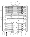
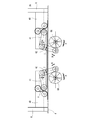
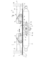
図1は、本発明による折り装置2の第1の実施形態による、図2の矢印Bの方向で見た上面図である。折り装置2は、図示されていない印刷ユニット及び場合によって断裁装置の下流に配置されており、前記印刷ユニット及び断裁装置から、折り畳まれる印刷された折り丁を受け取る。
FIG. 1 is a top view as seen in the direction of arrow B in FIG. 2 according to a first embodiment of a
折り装置2は、幅Iを備える折りテーブル4と、第1のフレーム6と、第2のフレーム8と、2つの折りローラ10及び12と、折りブレード14と、被動前進ベルトのセットと、ベルトの部分を折りテーブル4に対して移動させるための手段20,22とを有している。
The
折りローラ10及び12は、テーブル4に形成されたスロット24のそれぞれの側において折りテーブル4の下方に配置されている。折りブレード14はテーブル4の上方に配置されており、スロット24に挿入されるように下降させられることができる。折りブレード14は、折りテーブル4に対して垂直に延びた折り平面PPを規定している。折り丁ストッパ(図示せず)は、第1のフレーム6の近傍に配置されている。
The
被動前進ベルトのセットは、上部ベルトの第1のグループ16及び下部ベルトの関連するグループと、上部ベルトの第2のグループ18及び下部ベルトの関連するグループとを有している。移動手段20は第1のグループ16に結合されているのに対し、移動手段22は第2のグループ18に結合されている。
The set of driven forward belts has a
上部ベルトのグループ16及び18の構成及び作動と、移動手段20及び22の構成及び作動とは、同じである。実際、折り装置20は折り平面PPに対して対称の構成である。その結果、上部ベルトのグループ16と、関連する移動手段20との構成及び作動のみを説明する。
The configuration and operation of the
グループ16は、移動手段20が作用する複数の上部ベルトのセット、この場合にはa,b,c,dで示された4つのベルトと、移動手段を備えずに設けられた個々の上部ベルトeとを有している。
The
ベルトa〜eは、被動ベルトであり、駆動されて循環する。個々のベルトeは、スロット24に最も近いベルトである。
Belts a to e are driven belts and are driven to circulate. Each belt e is the belt closest to the
従って、スロット24を通過する折り丁は、ベルトeによって案内され、"バックラッシュ"による折りの形成が回避される。
Accordingly, the signature passing through the
各上部ベルトa〜dは、フレーム6及び8に結合された支持体38及び40に取り付けられた4つのプーリ48と、2つの可動プーリ46とを含む合計で6つのプーリによって支持されている(図2参照)。各可動プーリ46は、関連する上部ベルトのセクション49に対して押し付けられている。以下、これらのセクション49は、上部ベルトの"端部"という。
Each upper belt a to d is supported by a total of six pulleys including four
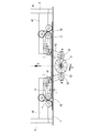
図2及び図3は、上部ベルトのグループ16に結合された下部ベルトのグループの下部ベルトδを示している。各上部ベルトa〜eはこのような対応する下部ベルトに関連している。
2 and 3 show the lower belt δ of the lower belt group coupled to the
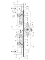
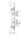
移動手段20は、上部ベルトa〜dを、折りテーブル4によって規定された前進平面26に対して、第1の低い位置Pb(図2参照)と、第2の高い位置Ph(図3参照)との間で移動させる。移動手段20は、折り平面PPと前進平面26とに対して垂直な鉛直方向中央平面28に対して対称に構成されている。移動手段20は、カム58が設けられた1つのカムシャフト30を有しており、前記カム58は、平面28のそれぞれの側において、回動アセンブリ32,34と協働する。
The moving means 20 moves the upper belts a to d to the first lower position Pb (see FIG. 2) and the second higher position Ph (see FIG. 3) with respect to the
カム58は、中心Oと、短軸Xと、長軸Yとを備えたほぼだ円形である。カム58の表面は、中心Oに近い表面セクション60と、中心Oから遠い表面セクション62とに分割されている。
The
各回動アセンブリ32,34は、2つの支持体38及び40において回動軸線X−Xを中心にして回動するように収容されたロッド36を有している。各回動アセンブリ32,34は、4つの支持レバー41のセットと、制御レバー42とを有している。
Each
各支持レバー41は、回動ロッド36に、この回動ロッド36に対して回動しないように固定された第1の端部50を有している。各支持レバー41は、回動軸線X−Xと一致する第1の端部50における回動軸線54を有している。各支持レバー41は、可動プーリ46の内の1つが設けられた第2の端部44も有している(図2参照)。各可動プーリ46は、関連する上部ベルトa,b,c,dを前進平面26に対して案内及び位置決めするために使用される。
Each
制御レバー42の向きは、支持レバー41の向きと異なる。制御レバー41は、支持レバー41に対して鈍角を形成している。
The direction of the
制御レバー42は第1の端部43を有しており、この第1の端部43において制御レバー42はロッド36に、このロッド36に対して回動しないように固定されている。制御レバー42は、支持レバー41の回動軸線及び回動軸線X−Xと一致する第1の端部43における回動軸線54を有している。
The
制御レバー42はカムシャフト30と協働する。具体的には、制御レバー42は、カムシャフト30のカム58と接触したカムローラ若しくはカムフォロア56が設けられた、第1の端部43とは反対側の第2の端部52を有している。
The
各回動アセンブリ32,34の制御レバー42のローラ56は、同じカム58と協働する。従って、カム58は、2つのローラ56によって共有されたカムである。
The
各ローラ56は、ばねエレメント(図示せず)によってカム58の表面に向かって付勢されている。これらのばねエレメントは、特に圧縮ばね又はねじりロッドである。
Each
ここで本発明による折り装置2の第1の実施態様の作動を図1から図3までを参照して説明する。
The operation of the first embodiment of the
折り畳まれる製品、すなわち印刷された折り丁は、直角折りを受けるために、装置2に向かって前進させられる。折りテーブル4における折り丁の前進方向は、図2に矢印Fによって示されている。各折丁は、折りテーブル4の幅I(図1参照)と実質的に等しい、幅、すなわち前進方向Fに対して垂直でかつ前進平面26に対して平行な横方向を有している。
The product to be folded, i.e. the printed signature, is advanced towards the
折り装置2の内部における、図2の左端に示された、折り丁Sの走行は、以下のとおりである。折り丁の幅に沿って、折り丁Sは、上部ベルトa〜eのグループ16及び18と、下部ベルトの対応するグループとの間に掴まれる。折り丁Sを折りテーブル4上で、折りブレード14の下方にこの折りブレード14と向き合うように前進させるために、上部及び下部ベルトは前進方向Fに駆動される。折り丁Sは、フレーム側6に配置されたストッパ(図示せず)を用いて折りテーブル4上で停止させられる。折り丁Sが停止させられると、折りブレード14は、図2に示された矢印Gに沿って下降させられる。折り丁Sの中央部は、折りブレード14のエッジの作用によりスロット24に押し込まれ、次いで、回転する折りローラ10及び12によって掴まれる。従って、折り丁Sは、いわゆる"直角折り"において折りが形成される。
The travel of the signature S shown at the left end of FIG. 2 inside the
本発明による移動手段20,22により、折り丁Sが特にストッパによって停止させられる前に、また、折り丁がテーブル4のスロット24においてブレード14によって係合される前に、折り丁Sがそれぞれ通過するとき、上部ベルトa〜dは下部ベルトから数ミリメートルだけ離れる。
By means of the movement means 20, 22 according to the invention, the signature S passes respectively before the signature S is stopped in particular by the stopper and before the signature is engaged by the
図2は、折りテーブル4に向かってベルトによって前進させ始める段階の折り丁Sを示している。上部ベルトは低い位置Pbにあり、折り丁を矢印Fの方向に駆動するのに十分な第1の前進圧力P1を折り丁Sに加えている。従って、折り丁Sは上部ベルトaと下部ベルトδとの間に掴まれる。上部ベルトaの低い位置Pbは、カム58の短軸Xの寸法によって規定される。実際には、低い位置Pbにおいて、制御レバー42のローラ56は、カム58の表面セクション60と接触している。従って、制御レバー42は、図2に示されたような引っ込められた位置にある。支持レバー41に取り付けられた可動プーリ46は低い位置にあり、上部ベルトaを折り丁Sの表面に押し付ける。
FIG. 2 shows the signature S at the stage where it starts to move forward by the belt toward the folding table 4. The upper belt is in the lower position Pb and applies a first advance pressure P1 to the signature S sufficient to drive the signature in the direction of arrow F. Therefore, the signature S is gripped between the upper belt a and the lower belt δ. The low position Pb of the upper belt a is defined by the dimension of the short axis X of the
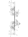
折り丁Sはベルトによって前進方向Fに折り位置に向かって前進させられる。この間、カム58は、図2に示された矢印Hに従って回転する。折り丁Sがストッパ(図示せず)に衝突しようとする時、カム58は4分の1回転だけ回転しており、図3に示された位置に到達する。制御レバー42のローラ56はカム面において転動し(矢印M参照)、カム58の表面セクション62と接触している。カム58のこの回転運動は、カム58の長軸Yによって規定された最大離間位置に向かって制御レバー42の離間を生じる。その結果、制御レバー42は、図3に示された矢印Jに従って、すなわち外方及び下方へ移動する。制御レバー42は、ロッド36及び支持レバー41を矢印Kによって示されているように駆動する。可動プーリ46が追従して移動し、これにより、上部ベルトaを図3に示された方向Dへ上昇させる。これにより、上部ベルトaと下部ベルトδとの間に、数ミリメートルの隙間iが生じる。従って、上部ベルトは解放位置にあり、上部ベルトは、前進圧力P1よりも小さい第2の圧力P2を折り丁Sに加える。第2の圧力P2は0Paに等しいこともでき、これにより、上部ベルトは解放位置Phにおいて、折り丁Sと接触しなくなる。
The signature S is advanced toward the folding position in the forward direction F by the belt. During this time, the
概して、第2の圧力P2は、0Paよりも大きいか又は0Paと等しく、好適には0Paよりも僅かに大きい。 In general, the second pressure P2 is greater than or equal to 0 Pa, preferably slightly greater than 0 Pa.
従って、折り丁Sは、直角折りを生じる前には著しく解放されない。これは、ストッパにおける折り丁Sの圧潰を減じ、ローラ10及び12による折り丁Sの掴みを容易にするという利点を有する。実際には、隙間iにより、折り丁Sの端部は、前進ベルトのグループからより容易に引き出される。
Thus, the signature S is not significantly released before a right-angle fold occurs. This has the advantage of reducing the collapse of the signature S at the stopper and facilitating the gripping of the signature S by the
折り丁Sの解放は、好適には、前記折り丁Sがストッパに衝突する前に行われる。従って、ストッパにおける折り丁の圧潰が減じられる。 The signature S is preferably released before the signature S collides with the stopper. Accordingly, the crushing of the signature at the stopper is reduced.
カムシャフト30は、折り畳まれる各折り丁Sのための上部ベルトを持ち上げるように駆動される。従って、上部ベルトa〜dは、図2及び図3に示された2つの位置Pb及びPhの間を交互に移動する。
The
カムシャフト30の回転は、制御装置(図示せず)によって、折り丁Sの前進周波数の半分とほぼ等しい周波数Frに調節される。
The rotation of the
図2及び図3に示されたようなほぼだ円形のカムの使用に限定されない。異なる形状のカム、又は偏心輪を考えることができ、回転の周波数Frは、選択されたカム又は偏心輪の形状に適応されなければならない。概して、周波数Frは、FrがFa/nに等しくなっており、この場合、Faは折り丁Sの前進周波数、nは正の整数である。 It is not limited to the use of a generally oval cam as shown in FIGS. Different shapes of cams or eccentrics can be considered, and the frequency of rotation F r must be adapted to the shape of the selected cam or eccentric. In general, the frequency F r is such that F r is equal to F a / n, where F a is the forward frequency of the signature S and n is a positive integer.
図4及び図5は、折り装置の第1の実施態様の第1の変更例である。この変更例は、以下のように前述の折り装置と異なる。この変更例において、唯一のシャフト30の代わりに、それぞれ制御レバー42の1つに作用する2つのカム66及びカムシャフト64が用いられている。共有されたカム58が2つの制御レバー42の間に配置されている図2及び図3とは異なり、2つのカム66の間に配置されているのは制御レバー42の端部52である。2つのカム66は同じ周波数で回転し、つまり、矢印Hで示したように、互いに反対方向で同期させられている。図4は、図2と同様に、低い位置Pbを示しており、図5は、図3と同様に、高い位置Phを示している。
4 and 5 show a first modification of the first embodiment of the folding device. This modified example is different from the above-described folding apparatus as follows. In this modification, instead of a
図6及び図7は、図4及び図5と同様の第2の択一例を示しており、2つのカム64の内の一方が固定されている点のみが異なる。図6の低い位置Pbは図4の位置と同じである。しかしながら、図7に示したように、1つの回転カム64を用いて、上部ベルトaは、一方の側においてのみ折りテーブル4に対して角度αを成すように上昇する。従って、高い位置Phにおいて、上部ベルトaは前進平面に対して傾斜させられている。
FIGS. 6 and 7 show a second alternative example similar to FIGS. 4 and 5 and differ only in that one of the two
図示の場合、ベルトは、ベルトが折り丁の前側において、つまり前進方向Fの下流に向かって上昇させられるように傾斜させられる。 In the case shown, the belt is tilted so that the belt is raised in front of the signature, ie downstream in the forward direction F.
択一的に、位置Phにおいて、ベルトは、折り丁の後側において、つまり前進方向Fの上流に向かって上昇させられるようにテーブル4に対して傾斜させられる。 Alternatively, at position Ph, the belt is tilted with respect to the table 4 so as to be raised behind the signature, ie upstream in the forward direction F.
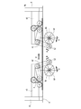
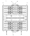
図8から図10までは、本発明による折り装置の第2の実施態様3を示している。この第2の実施態様は、上部ベルトa〜dの2つのセットを移動させるための手段20及び22に関して第1の実施態様と同じである。しかしながら、この実施態様において、定時に昇降させられる上部ベルトは、折り丁を前進させるためのベルトではなく、付加的な静止した制動ベルトである。付加的な上部ベルトa〜dは、駆動されず、端部68においてねじ70を用いて支持体38,40に固定されている。付加的な上部制動ベルトa〜dは、上部前進ベルトe及び下部前進ベルトδの間に収容されている。
FIGS. 8 to 10 show a
本発明による折り装置の第2の実施態様3は以下のように作動する。図9を参照すると、折り丁Sは、前進ベルトe,δによって折りテーブル4上で矢印Fによって示された方向に前進させられる。前進の開始時には、上部制動ベルトaは高い位置Phにあり、前進ベルトeに対して約数ミリメートルの隙間iだけ高さがずれている。ローラ56はカム58の表面セクション62と接触しており、2つの制御レバー42は互いにより離れた位置にある。折り丁Sが折りテーブル4上で前進方向Fに移動し続けると、カム58は、図10に示された位置に達するまで回転し続ける。この位置において、カム表面に従動するローラ56はカム58の表面60と接触している。従って、矢印Jによって示されたように制御レバー42は互いに向かって上方へ回動し、より近づいた位置へ達し、上部制動ベルトaを下降させる。
The
カムシャフト30の回転の周波数及び位相は、折り丁Sが折りテーブル4のスロット24において折りブレード14によって係合され、折りローラ10,12によって掴まれる前に折り丁Sを制動するために、折り丁Sのそれぞれの通過時に上部制動ベルトa〜dが下降するように、調節される。移動している折り丁Sに向かって下降することにより、上部制動ベルトa〜dは折り丁Sと接触し、摩擦によって折り丁Sを制動する。制動の間、カム58は、図9に示された位置に再び達するまで回転し続ける。上部制動ベルトが上昇させられると、折り丁Sは折り畳まれ、前記サイクルは再び開始する。カムシャフト30の回転の周波数Frは、FrがFa/nに等しくなるように調節され、この場合、Faは折り畳まれる製品の前進周波数であり、nは正の整数である。
The frequency and phase of rotation of the
2つの実施態様、すなわち前進ベルトを上昇させるための定時システムと、制動ベルトのグループの定時下降による制動システムとは、別個に説明された。しかしながら、これらの2つのシステムは組み合わされてもよい。 Two embodiments have been described separately, a timed system for raising the forward belt and a braking system with a timed lowering of a group of brake belts. However, these two systems may be combined.
さらに、上述のベルトの定時移動のための手段20,22を、完全に折りテーブルの下方に配置することもできる。さらに、上で展開された原理を、下部前進ベルトに適用することもできる。その場合は、定時形式で移動させられるのは下部ベルトδであり、上部ベルトではない。
Furthermore, the
移動手段20,22を、前記実施態様とは異なる数のベルトを移動させるように変更することもできる。図1を参照すると、例えば、ロッド36をベルトeまで延長し、ベルトa〜dと一緒にベルトeの定時上昇を可能にする付加的な支持レバー41を提供することも可能である。それとは逆に、定時移動を例えばベルトa及びbだけに限定するために移動手段20,22を変更することも可能である。所望の用途に応じてその他の択一例も考えられる。
The moving means 20 and 22 can be changed so as to move a different number of belts from the above embodiment. Referring to FIG. 1, for example, it is also possible to provide an
もちろん、レバー41,42を、カムシャフト以外の手段により作動させることができる。カムシャフトの代わりに例えばジャッキ又は電磁石を用いることができる。
Of course, the
2 折り装置、 4 折りテーブル、 6 第1のフレーム、 8 第2のフレーム、 10,12 折りローラ、 14 折りブレード、 16 第1のグループ、 18 第2ングループ、 20,22 移動手段、 24 スロット、 26 前進平面、 30 カムシャフト、 32,34 回動アセンブリ、 36 ロッド、 38,40 支持体、 41 支持レバー、 42 制御レバー、 43 第1の端部、 44 第2の端部、 46 可動プーリ、 48 プーリ、 49 セクション、 50 第1の端部、 56 カムフォロア、 58 カム、 60,62 表面セクション、 a〜e 上部ベルト、 δ 下部ベルト、 S 折り丁、 P1 前進圧力、 P2 第2の圧力、 i 隙間 2 folding device, 4 folding table, 6 first frame, 8 second frame, 10, 12 folding roller, 14 folding blade, 16 first group, 18 second group, 20, 22 moving means, 24 slots , 26 forward plane, 30 camshaft, 32, 34 pivot assembly, 36 rod, 38, 40 support, 41 support lever, 42 control lever, 43 first end, 44 second end, 46 movable pulley , 48 pulley, 49 section, 50 first end, 56 cam follower, 58 cam, 60, 62 surface section, ae upper belt, δ lower belt, S signature, P1 forward pressure, P2 second pressure, i Clearance
Claims (15)
折り部材(14)と、
折り畳まれる製品(S)を前記折り部材(14)と向き合って配置するために前記製品に前進平面(26)において作用する少なくとも1つの第1のベルト(d)と、
各第1のベルト(d)を前進平面に対して、第1のベルト(d)が折り畳まれる製品(S)に第1の圧力(P1)を加える第1の位置(Pb)と、第1のベルト(d)が折り畳まれる製品(S)に第1の圧力(P1)よりも小さい第2の圧力(P2)を加える第2の位置(Ph)との間で移動させるための移動手段(20,22)とが設けられている形式のものにおいて、
前記移動手段(20,22)が、第1のベルト(d)を第1の位置と第2の位置との間で交互に移動させることを特徴とする、折り装置。 In the folding device (2, 3),
A folding member (14);
At least one first belt (d) acting on the product in an advancing plane (26) to position the product (S) to be folded against the folding member (14);
A first position (Pb) for applying a first pressure (P1) to a product (S) in which each first belt (d) is folded with respect to the advancing plane; Moving means for moving between the second position (Ph) to apply a second pressure (P2) smaller than the first pressure (P1) to the product (S) in which the belt (d) is folded 20 and 22) are provided,
The folding device, wherein the moving means (20, 22) moves the first belt (d) alternately between a first position and a second position.
周囲に前記第1のベルト(d)が案内された第1の案内部材(46)と、
該第1の案内部材(46)を支持する第1の可動支持部材(41)と、
第1のベルト(d)を第1の位置(Pb)と第2の位置(Ph)との間で移動させるための、第1の可動支持部材(41)の定時往復作動のための第1の定時作動手段(30)とを有している、請求項1記載の折り装置。 Each first belt moving means (20, 22) for each first belt,
A first guide member (46) around which the first belt (d) is guided;
A first movable support member (41) for supporting the first guide member (46);
A first reciprocating operation of the first movable support member (41) for moving the first belt (d) between the first position (Pb) and the second position (Ph). The folding device according to claim 1, further comprising:
周囲に前記第1のベルト(d)が案内された第2の案内部材(46)と、
該第2の案内部材(46)を支持する第2の可動支持部材(41)と、
第1のベルト(d)を第1の位置(Pb)と第2の位置(Ph)との間で移動させるための、第2の可動支持部材(41)の定時往復作動のための第2の定時作動手段(30;64)とを有している、請求項2記載の折り装置。 Each first belt moving means (20, 22) for each first belt,
A second guide member (46) around which the first belt (d) is guided;
A second movable support member (41) for supporting the second guide member (46);
A second for a reciprocating operation of the second movable support member (41) for moving the first belt (d) between the first position (Pb) and the second position (Ph). The folding device according to claim 2, further comprising a fixed-time operation means (30; 64).
Applications Claiming Priority (2)
| Application Number | Priority Date | Filing Date | Title |
|---|---|---|---|
| FR0959652 | 2009-12-29 | ||
| FR0959652A FR2954757B1 (en) | 2009-12-29 | 2009-12-29 | FOLDING DEVICE COMPRISING ONE OR MORE BELTS CAPABLE OF PERFORMING A CADENCE MOVEMENT BETWEEN TWO POSITIONS |
Publications (1)
| Publication Number | Publication Date |
|---|---|
| JP2011136841A true JP2011136841A (en) | 2011-07-14 |
Family
ID=42340714
Family Applications (1)
| Application Number | Title | Priority Date | Filing Date |
|---|---|---|---|
| JP2010290910A Pending JP2011136841A (en) | 2009-12-29 | 2010-12-27 | Folding device comprising one or more belts for carrying out alternating movement between two positions |
Country Status (5)
| Country | Link |
|---|---|
| US (1) | US20110212816A1 (en) |
| EP (1) | EP2341026B1 (en) |
| JP (1) | JP2011136841A (en) |
| CN (1) | CN102180377A (en) |
| FR (1) | FR2954757B1 (en) |
Families Citing this family (1)
| Publication number | Priority date | Publication date | Assignee | Title |
|---|---|---|---|---|
| CN109928259B (en) * | 2019-02-28 | 2020-07-28 | 亿信医疗器械股份有限公司 | Continuous folding device of multilayer gauze piece |
Citations (4)
| Publication number | Priority date | Publication date | Assignee | Title |
|---|---|---|---|---|
| JPS6286353U (en) * | 1985-11-20 | 1987-06-02 | ||
| JPH0761687A (en) * | 1993-08-25 | 1995-03-07 | Sharp Corp | Sheet post-processing device |
| JPH09301628A (en) * | 1996-05-16 | 1997-11-25 | Mitsubishi Heavy Ind Ltd | Method and device for carrying sheet or the like for folder |
| JP2002174862A (en) * | 2000-12-07 | 2002-06-21 | Fuji Photo Film Co Ltd | Image forming device |
Family Cites Families (13)
| Publication number | Priority date | Publication date | Assignee | Title |
|---|---|---|---|---|
| US3507489A (en) * | 1966-09-06 | 1970-04-21 | Masson Scott Thrissell Eng Ltd | Sheet feeding apparatus |
| US4281828A (en) * | 1978-03-30 | 1981-08-04 | Union Carbide Corporation | Plastic bag handling system |
| FR2546818B1 (en) * | 1983-06-06 | 1987-03-20 | Marinoni Harris Sa | DEVICE FOR SLOWING DOWN COPIES IN A FOLDING SQUARE FOLDER USED IN CONNECTION WITH ROTATING PRESSES |
| FR2563773B1 (en) * | 1984-05-07 | 1986-12-05 | Marinoni Harris Sa | DEVICE FOR AUTOMATICALLY ADJUSTING THE SLOWDOWN OF THE NOTEBOOK BEFORE FOLDING IN THE FOLDERS OF THE PRESS FOLDER SQUARES |
| FR2672544B1 (en) * | 1991-02-08 | 1995-10-06 | Marinoni Harris Sa | FOLDER OF PRINTING MACHINE WITH DEVICE FOR SLOWING COPIES SENT IN A SQUARE FOLDER OF SAID FOLDER. |
| GB2255551B (en) * | 1991-05-10 | 1995-01-18 | Frankenthal Ag Albert | Feeding signatures to a reciprocating blade folder |
| JPH06115805A (en) * | 1992-10-09 | 1994-04-26 | Kao Corp | Bending device for soft materials |
| GB2281069B (en) * | 1993-08-17 | 1997-04-23 | Rockwell Pmc Limited | Folding apparatus |
| JPH115668A (en) * | 1997-06-13 | 1999-01-12 | Komori Corp | Chopper device |
| JP3891665B2 (en) * | 1997-10-15 | 2007-03-14 | 三菱重工業株式会社 | Sheet folding machine |
| JP3835933B2 (en) * | 1998-02-27 | 2006-10-18 | 三菱重工業株式会社 | Folding machine signature transport device |
| JP3692322B2 (en) * | 2000-12-25 | 2005-09-07 | 三菱重工業株式会社 | Eclectic conveyor |
| DE102004023318B4 (en) * | 2004-05-07 | 2008-04-17 | Man Roland Druckmaschinen Ag | Folding device for printing presses or folders |
-
2009
- 2009-12-29 FR FR0959652A patent/FR2954757B1/en not_active Expired - Fee Related
-
2010
- 2010-12-27 JP JP2010290910A patent/JP2011136841A/en active Pending
- 2010-12-28 EP EP10306525.6A patent/EP2341026B1/en not_active Not-in-force
- 2010-12-29 US US12/980,997 patent/US20110212816A1/en not_active Abandoned
- 2010-12-29 CN CN2010106251058A patent/CN102180377A/en active Pending
Patent Citations (4)
| Publication number | Priority date | Publication date | Assignee | Title |
|---|---|---|---|---|
| JPS6286353U (en) * | 1985-11-20 | 1987-06-02 | ||
| JPH0761687A (en) * | 1993-08-25 | 1995-03-07 | Sharp Corp | Sheet post-processing device |
| JPH09301628A (en) * | 1996-05-16 | 1997-11-25 | Mitsubishi Heavy Ind Ltd | Method and device for carrying sheet or the like for folder |
| JP2002174862A (en) * | 2000-12-07 | 2002-06-21 | Fuji Photo Film Co Ltd | Image forming device |
Also Published As
| Publication number | Publication date |
|---|---|
| EP2341026B1 (en) | 2013-11-27 |
| FR2954757B1 (en) | 2012-04-27 |
| CN102180377A (en) | 2011-09-14 |
| US20110212816A1 (en) | 2011-09-01 |
| FR2954757A1 (en) | 2011-07-01 |
| EP2341026A1 (en) | 2011-07-06 |
Similar Documents
| Publication | Publication Date | Title |
|---|---|---|
| JP5786009B2 (en) | Digitally printed newspaper production equipment | |
| JP5804701B2 (en) | Paper cutting device | |
| US6508153B1 (en) | Conveyor product transfer apparatus and method | |
| JP5441451B2 (en) | Device for adjusting the position of a sheet with a stopper | |
| JP2011136841A (en) | Folding device comprising one or more belts for carrying out alternating movement between two positions | |
| JPH11263531A (en) | Folding device for rotary press printer and method of delivering end part of sheet material | |
| JP4150096B2 (en) | Apparatus for forming partial deposits extending perpendicularly to standing printed paper sheets | |
| US9969155B2 (en) | Print sheet brake | |
| KR20130136273A (en) | Automatic sheet feeder for thomson cutter | |
| US20120128461A1 (en) | Stacking device for groups of disposable wipes | |
| KR20110000218A (en) | Tissue Stacking Device for Wallet Tissue Automatic Packaging Machine | |
| KR102348029B1 (en) | Device and method for forming an overlapping stream of under- or overlapping sheets | |
| EP1934124B1 (en) | Method for synchronising a longitudinal folding machine | |
| US7575545B2 (en) | Longitudinal folding device | |
| JP2003341906A (en) | Sheet feeding device | |
| JP2017202585A (en) | Device for cutting and transferring handles | |
| US3752469A (en) | Folding machine and method of pressing a fold | |
| US7458926B2 (en) | Quarter folder apparatus | |
| CZ2002661A3 (en) | Arrangement for stitching the spine of printed products, compiled of folded printed sheets, by means of staples | |
| US20110100781A1 (en) | Method and device for producing stacks composed of printed products | |
| JP3201509U (en) | Device for deriving a sheet | |
| JP4050757B2 (en) | Folding device for printing machine or folding machine | |
| CN110775670A (en) | Device for outputting printed products of the same or different thickness and method for transferring printed products to a sheet transport device | |
| JP5558919B2 (en) | Booklet binding machine with folding roller | |
| CN104936876A (en) | Machine for the formation of numbered packs of interleaved sheets of paper |
Legal Events
| Date | Code | Title | Description |
|---|---|---|---|
| A621 | Written request for application examination |
Free format text: JAPANESE INTERMEDIATE CODE: A621 Effective date: 20131202 |
|
| A977 | Report on retrieval |
Free format text: JAPANESE INTERMEDIATE CODE: A971007 Effective date: 20141029 |
|
| A131 | Notification of reasons for refusal |
Free format text: JAPANESE INTERMEDIATE CODE: A131 Effective date: 20141104 |
|
| A02 | Decision of refusal |
Free format text: JAPANESE INTERMEDIATE CODE: A02 Effective date: 20150406 |