JP2011136821A - Pasting device - Google Patents

Pasting device Download PDF

Info

Publication number
JP2011136821A
JP2011136821A JP2009298791A JP2009298791A JP2011136821A JP 2011136821 A JP2011136821 A JP 2011136821A JP 2009298791 A JP2009298791 A JP 2009298791A JP 2009298791 A JP2009298791 A JP 2009298791A JP 2011136821 A JP2011136821 A JP 2011136821A
Authority
JP
Japan
Prior art keywords
paper
gluing
glue
sheet
clamping member
Prior art date
Legal status (The legal status is an assumption and is not a legal conclusion. Google has not performed a legal analysis and makes no representation as to the accuracy of the status listed.)
Pending
Application number
JP2009298791A
Other languages
Japanese (ja)
Inventor
Tomio Honma
富雄 本間
Current Assignee (The listed assignees may be inaccurate. Google has not performed a legal analysis and makes no representation or warranty as to the accuracy of the list.)
Duplo Corp
Original Assignee
Duplo Corp
Priority date (The priority date is an assumption and is not a legal conclusion. Google has not performed a legal analysis and makes no representation as to the accuracy of the date listed.)
Filing date
Publication date
Application filed by Duplo Corp filed Critical Duplo Corp
Priority to JP2009298791A priority Critical patent/JP2011136821A/en
Publication of JP2011136821A publication Critical patent/JP2011136821A/en
Pending legal-status Critical Current

Links

Images
Landscapes

  • Folding Of Thin Sheet-Like Materials, Special Discharging Devices, And Others (AREA)

Abstract

【課題】簡易な構成で用紙に適切に糊付け可能な糊付け装置を提供する。
【解決手段】糊付け装置14において、第2用紙載置台60は、糊付けローラ120と共に用紙を挟持する。駆動機構44は、糊付けローラ120および第2用紙載置台60がそれらの間に送り込まれた用紙を挟持するよう糊付けローラ120を進行させる。筐体38は、第2用紙載置台60を回動可能に支持する。糊付けローラ120は、用紙の挟持開始後さらに糊付けローラ120が進行したときに、第2用紙載置台60に与える抗力によって第2用紙載置台60を回動させながら、第2用紙載置面60aに沿って糊シートの裏面上を走行するよう設けられる。駆動機構44は、用紙の挟持開始後さらに糊付けローラ120を進行させることにより、糊シートの裏面上を糊付けローラ120に走行させて糊シートの糊付着面を用紙に押し付け、用紙に糊を転写させる。
【選択図】図3
A gluing device capable of appropriately gluing paper with a simple configuration is provided.
In a gluing device, a second paper placing table 60 holds a paper together with a gluing roller. The drive mechanism 44 advances the gluing roller 120 so that the gluing roller 120 and the second paper placing table 60 hold the paper fed between them. The housing 38 supports the second paper placing table 60 so as to be rotatable. The gluing roller 120 is placed on the second paper placing surface 60a while rotating the second paper placing table 60 by a drag force applied to the second paper placing table 60 when the pasting roller 120 further proceeds after the start of paper clamping. It is provided so that it may run on the back surface of the glue sheet along. The drive mechanism 44 further advances the gluing roller 120 after starting the nipping of the paper, thereby causing the gluing roller 120 to run on the back surface of the glue sheet, pressing the glue adhering surface of the glue sheet against the paper, and transferring the glue to the paper. .
[Selection] Figure 3

Description

本発明は、糊付け装置に関し、特に、糊シートを用いた糊付け装置に関する。   The present invention relates to a gluing device, and more particularly to a gluing device using a glue sheet.

基材シートの片面に糊が付着されている糊シートが知られている。この糊シートの糊付着面を糊付けしたい個所に押し付けることで用紙などに糊付けすることができる。ここで、用紙に糊シートを押し付けることにより、糊シートを巻き取って未転写の糊シートを押し付け可能とする接着剤ディスペンサが提案されている(例えば、特許文献1参照)。   A glue sheet in which glue is attached to one side of a base sheet is known. By pressing the glue-attached surface of the glue sheet on the place to be glued, it can be glued to a sheet or the like. Here, an adhesive dispenser has been proposed in which a paste sheet is pressed against a sheet so that the paste sheet can be taken up and an untransferred paste sheet can be pressed (see, for example, Patent Document 1).

特表平6−510267号公報JP-T 6-510267

上述の特許文献に記載される技術では、広い領域に糊付けしたい場合は押圧面を広くとる必要があるが、押圧面を広くすることによって糊シートを押し付ける圧力が低下するおそれがある。このため、糊の良好な転写を維持するために糊シートを強い力で用紙に押し付ける必要が生じる。しかしながら、このような押し付け力の増大は、糊シートを押し付けるユーザまたは押し付け機構などに負担に繋がり、ユーザの作業労力の軽減または装置の信頼性の維持が困難となる。   In the technique described in the above-mentioned patent document, it is necessary to widen the pressing surface when it is desired to paste in a wide area, but there is a possibility that the pressure for pressing the glue sheet may be reduced by widening the pressing surface. For this reason, in order to maintain a good transfer of glue, it is necessary to press the glue sheet against the paper with a strong force. However, such an increase in pressing force leads to a burden on the user pressing the glue sheet or the pressing mechanism, and it becomes difficult to reduce the user's work effort or maintain the reliability of the apparatus.

本発明はこのような問題に鑑みてなされたものであり、その目的は、簡易な構成で用紙に適切に糊付け可能な糊付け装置を提供することにある。   The present invention has been made in view of such problems, and an object of the present invention is to provide a gluing device capable of appropriately gluing paper with a simple configuration.

上記課題を解決するために、本発明のある態様の糊付け装置は、一方の面に糊が付着された糊シートの糊付着面の裏面と接する糊付けヘッドと、糊付けヘッドと共に用紙を挟持する挟持部材と、糊付けヘッドおよび挟持部材がそれらの間に送り込まれた用紙を挟持するよう糊付けヘッドまたは挟持部材を進行させる駆動機構と、を備える。糊付けヘッドは、用紙の挟持開始後さらに糊付けヘッドまたは挟持部材が進行したときに、挟持部材との間に互いに発生する抗力によって挟持部材の表面に沿って糊シートの裏面上を走行するよう設けられてもよい。駆動機構は、用紙の挟持開始後さらに糊付けヘッドまたは挟持部材を進行させることにより、糊シートの裏面上を糊付けヘッドに走行させて糊シートの糊付着面を用紙に押し付け、用紙に糊を転写させる。   In order to solve the above-described problems, a gluing device according to an aspect of the present invention includes a gluing head that is in contact with the back surface of a gluing surface of a gluing sheet that has gluing adhered to one side thereof, and a clamping member that holds the paper together with the gluing head. And a drive mechanism for advancing the glueing head or the clamping member so as to clamp the paper fed between the glueing head and the clamping member. The gluing head is provided to run on the back surface of the glue sheet along the surface of the clamping member by the drag generated between the clamping member and the clamping member when the gluing head or the clamping member further advances after the sheet clamping is started. May be. The drive mechanism further advances the gluing head or the clamping member after starting the clamping of the paper, so that the gluing head runs on the back surface of the glue sheet, presses the glue adhesion surface of the glue sheet to the paper, and transfers the glue to the paper. .

この態様によれば、挟持する面積が小さくても糊付けヘッドに糊シートの裏面上を走行させることによって、広い面積を糊付けすることができる。このため、挟持力を抑制しつつ適切に用紙に糊を転写することができる。なお、糊付けヘッドは、糊シートの裏面に外周が接し、糊シートの裏面上を転動して走行可能な糊付けローラを含んでいてもよい。   According to this aspect, even if the sandwiched area is small, a wide area can be glued by causing the glueing head to run on the back surface of the glue sheet. For this reason, it is possible to appropriately transfer the glue to the paper while suppressing the clamping force. Note that the gluing head may include a gluing roller whose outer periphery is in contact with the back surface of the glue sheet and capable of running by rolling on the back surface of the glue sheet.

挟持部材を回動可能に支持する筐体をさらに備えてもよい。糊付けヘッドは、用紙の挟持開始後さらに糊付けヘッドまたは挟持部材が進行したときに、挟持部材に与える抗力によって挟持部材を回動させながら、挟持部材の表面に沿って糊シートの裏面上を走行するよう設けられてもよい。   You may further provide the housing | casing which supports a clamping member rotatably. The glueing head travels on the back surface of the glue sheet along the surface of the sandwiching member while rotating the sandwiching member by the drag applied to the sandwiching member when the glueing head or the sandwiching member further advances after the sheet clamping is started. It may be provided as follows.

この態様によれば、挟持部材を回動させるという簡易な構成によって、糊付けヘッドまたは挟持部材の進行動作を、糊付けヘッドの走行動作に変換することができる。このため、例えば糊付けヘッドをその進行方向以外の方向にも移動させる機構を別途設けることにより糊付けヘッドを走行させる場合に比べ、構成を簡素にすることができ、低コストの糊付け装置を提供することができる。   According to this aspect, the advancing operation of the gluing head or the clamping member can be converted into the traveling operation of the gluing head with a simple configuration in which the clamping member is rotated. For this reason, for example, by providing a separate mechanism for moving the gluing head in a direction other than its traveling direction, the configuration can be simplified and a low-cost gluing device can be provided as compared with the case where the gluing head is run. Can do.

挟持部材は平面状の挟持面を有してもよい。糊付けヘッドは、用紙の挟持開始後さらに糊付けヘッドまたは挟持部材が進行したときに、挟持面に沿って糊シートの裏面上を走行するよう設けられてもよい。駆動機構は、挟持部材が未回動のときの挟持面に、挟持部材の回動軸から離間するほど近づくよう傾斜する方向に、糊付けヘッドまたは挟持部材を進行させてもよい。   The clamping member may have a planar clamping surface. The gluing head may be provided so as to run on the back surface of the glue sheet along the nipping surface when the gluing head or the nipping member further proceeds after the sheet nipping is started. The drive mechanism may cause the gluing head or the clamping member to advance in a direction in which the clamping mechanism approaches the clamping surface when the clamping member is not rotated so as to be closer to the clamping shaft of the clamping member.

この態様によれば、糊付けヘッドまたは挟持部材の進行距離に対する糊付けヘッドの走行距離を長くすることができる。このため、糊付けヘッドまたは挟持部材の進行距離を抑制することができ、装置の大型化を回避することができる。   According to this aspect, it is possible to increase the travel distance of the gluing head with respect to the travel distance of the gluing head or the clamping member. For this reason, the advancing distance of the gluing head or the clamping member can be suppressed, and the enlargement of the apparatus can be avoided.

挟持部材を保持する保持機構と、用紙を押さえつける用紙押さえ部材と、をさらに備えてもよい。駆動機構は、用紙の挟持開始後さらに糊付けヘッドまたは挟持部材を進行させた後、用紙の挟持を解除させるよう糊付けヘッドまたは挟持部材を退避させ、保持機構は、糊付けヘッドまたは挟持部材が退避するときに、所定の保持位置で挟持部材を保持し、用紙押さえ部材は、糊シートから用紙を剥がすよう、保持位置に保持された挟持部材に用紙を押さえつけてもよい。   You may further provide the holding mechanism which hold | maintains a clamping member, and the paper pressing member which presses down a paper. The drive mechanism further advances the gluing head or the clamping member after starting the clamping of the paper, and then retracts the gluing head or the clamping member so as to release the clamping of the paper, and the holding mechanism is used when the gluing head or the clamping member is retracted. In addition, the holding member may be held at a predetermined holding position, and the paper pressing member may press the paper against the holding member held at the holding position so as to peel the paper from the glue sheet.

この態様によれば、用紙に糊シートを押し付けたあと、糊シートを用紙から適切に剥がして用紙に糊を転写させることができる。   According to this aspect, after the glue sheet is pressed against the paper, the glue sheet can be appropriately peeled off the paper to transfer the glue onto the paper.

保持機構は、糊付けヘッドまたは挟持部材が所定位置まで退避したときに、その退避動作に連動して挟持部材の保持を解除してもよい。   The holding mechanism may release the holding of the clamping member in conjunction with the retracting operation when the gluing head or the clamping member is retracted to a predetermined position.

この態様によれば、糊付けヘッドまたは挟持部材を退避させることで挟持部材の保持も解除することができる。このため、例えば退避動作に連動せず挟持部材の保持を解除する場合に比べ、装置の構成や制御などを簡素にすることができる。   According to this aspect, the holding of the clamping member can also be released by retracting the gluing head or the clamping member. For this reason, compared with the case where holding | maintenance of a clamping member is cancelled | released, for example, without interlock | cooperating with retracting operation, a structure, control, etc. of an apparatus can be simplified.

筐体に設けられた位置決め部材に突き当てて所定の初期位置に位置させるよう挟持部材に付勢力を与える付勢部材と、挟持部材が保持位置から初期位置へ戻るときの挟持部材の移動速度を緩める緩衝手段と、をさらに備えてもよい。   A biasing member that applies a biasing force to the clamping member so as to abut on a positioning member provided in the housing and be positioned at a predetermined initial position, and a moving speed of the clamping member when the clamping member returns from the holding position to the initial position. And a buffering means for loosening.

挟持部材が付勢部材によって初期位置に戻る方向に付勢されている場合、保持が解除されるとその付勢力によって初期位置に戻ろうとして挟持部材が加速し、初期位置において位置決めされるときに、装置に衝撃を与えたり、騒音を発生させる虞がある。この態様によれば、挟持部材の移動速度を緩めることができるため、挟持部材の保持を解除するときの衝撃や騒音を緩和することができる。   When the holding member is urged in a direction to return to the initial position by the urging member, when the holding is released, the holding member is accelerated to return to the initial position by the urging force, and is positioned at the initial position. There is a risk of impacting the device or generating noise. According to this aspect, since the moving speed of the clamping member can be reduced, it is possible to mitigate the impact and noise when releasing the holding of the clamping member.

糊付けヘッドを回動可能に支持する支持部材をさらに備えてもよい。駆動機構は、糊付けヘッドおよび挟持部材がそれらの間に送り込まれた用紙を挟持するよう糊付けヘッドまたは挟持部材を進行させるよう設けられてもよい。糊付けヘッドは、用紙の挟持開始後さらに糊付けヘッドまたは挟持部材が進行したときに、挟持部材から与えられる抗力によって支持部材に対して回動しながら、挟持部材の表面に沿って糊シートの裏面上を走行するよう設けられてもよい。   A support member that rotatably supports the gluing head may be further provided. The drive mechanism may be provided so that the gluing head or the clamping member advances so that the gluing head and the clamping member clamp the paper fed between them. The gluing head moves on the back surface of the glue sheet along the surface of the nipping member while rotating with respect to the support member by the drag applied from the nipping member when the gluing head or the nipping member further advances after the nipping of the paper starts. May be provided to travel.

このように糊付けヘッドが回動する態様においても、糊付けヘッドを糊シートの裏面に沿って走行させることができる。   Thus, also in the aspect in which the gluing head rotates, the gluing head can be run along the back surface of the glue sheet.

糊付けヘッドおよび挟持部材が用紙を挟持してから次に用紙を挟持するまでの間に、糊シートのうち糊付けヘッドに当接する部分の糊付着面に糊が未転写の部分が含まれるよう糊シートを送る予備送り機構をさらに備えてもよい。   Between the time when the gluing head and the clamping member pinch the paper and the time when the paper is held next, the glue sheet is such that the part to which the glue does not transfer is included in the glue adhering surface of the part of the glue sheet that contacts the gluing head May be further provided.

糊シートの糊付着面を用紙に押し付けた後糊シートを用紙から剥がすと、糊シートは糊が転写されるためその部分の粘着力が低下する。このまま次の用紙に糊シートを押し付けて糊付けヘッドを糊シートの裏面上を走行させようとすると、用紙と糊シートとの間の摩擦力が低下して糊シートが用紙に対してスリップし、糊付けヘッドとともに糊シートが移動して糊シートの裏面上を糊ヘッドが走行できなくなる可能性がある。このように糊シートが糊付けヘッドと共に移動すると、糊シートの糊転写済みの表面が用紙上を摺動するだけで糊シートの糊未転写部分を用紙に押し付けることが困難となる。この態様によれば、糊シートのうち糊が未転写の部分を用紙にまず押し付けることができるため、糊シートと用紙との間の摩擦力を確保することができる。このため、糊付けヘッドを走行させるときの糊シートの摺動を抑制でき、糊付けヘッドに糊シートの裏面上を良好に走行させることができる。   When the adhesive sheet is pressed against the paper and then peeled off from the paper, the adhesive is transferred to the adhesive sheet, and the adhesive strength of the adhesive sheet decreases. If the glue sheet is pressed against the next sheet as it is and the glue head is allowed to run on the back side of the glue sheet, the frictional force between the sheet and the glue sheet will drop, causing the glue sheet to slip against the sheet and glue. There is a possibility that the glue sheet moves with the head and the glue head cannot run on the back surface of the glue sheet. When the glue sheet moves together with the gluing head in this way, it becomes difficult to press the glue-untransferred portion of the glue sheet against the sheet only by sliding the glue-transferred surface of the glue sheet on the sheet. According to this aspect, since the portion of the glue sheet to which the glue has not been transferred can be first pressed against the paper, the frictional force between the glue sheet and the paper can be ensured. For this reason, sliding of the glue sheet when the glue head is run can be suppressed, and the glue sheet can be favorably run on the back surface of the glue sheet.

糊付けヘッドと挟持部材との間に用紙を送り込む用紙搬入機構と、糊付けヘッドと挟持部材との間に送り込まれた用紙の端部が当接するストッパと、複数の用紙を含む冊子を作成する製本要求を取得する製本要求取得部と、をさらに備えてもよい。用紙搬入機構は、製本要求が取得された場合、作成する冊子に含ませるべき用紙を糊付けヘッドと挟持部材との間に送り込んだ後、作成する冊子に含ませるべき次の用紙を、すでに送り込まれた用紙と糊付けヘッドとの間に送り込むよう設けられてもよい。駆動機構は、製本要求が取得された場合、送り込まれた用紙の端部がストッパに当接するたびに、その用紙に糊を転写させるよう糊付けヘッドまたは挟持部材を進行させてもよい。   A bookbinding request to create a booklet that contains a plurality of papers, a paper carry-in mechanism that feeds paper between the gluing head and the clamping member, a stopper that contacts the end of the paper that is fed between the gluing head and the clamping member And a bookbinding request acquisition unit for acquiring. When a bookbinding request is acquired, the paper carry-in mechanism sends the paper to be included in the booklet to be created between the gluing head and the clamping member, and then the next paper to be included in the booklet to be created has already been sent. It may be provided so as to be fed between the sheet and the gluing head. When the bookbinding request is acquired, the drive mechanism may advance the gluing head or the clamping member so that the glue is transferred to the paper every time the end of the fed paper comes into contact with the stopper.

この態様によれば、このような糊付けを繰り返すことによって冊子を作成することができる。さらに、搬入された用紙に糊シートを押し付けることによって、用紙への糊付けとともに糊付けした用紙と挟持部材との間の用紙を互いに圧着させることができる。   According to this aspect, a booklet can be created by repeating such gluing. Further, by pressing the glue sheet on the carried-in paper, the paper between the glued paper and the sandwiching member can be pressed together with the glue on the paper.

隣接する用紙同士の少なくとも一方に糊が転写された複数の用紙を挟持して圧着させる圧着処理を実行する圧着機構と、糊付けヘッドと挟持部材との間に送り込まれた複数の用紙を圧着機構に送り出す用紙搬出機構と、をさらに備えてもよい。駆動機構は、製本要求が取得された場合、作成すべき冊子に含ませるべき複数の用紙のうち最後に送り込まれた最終用紙への糊の転写を回避するよう、糊付けヘッドまたは挟持部材の進行を回避し、用紙搬出機構は、最終用紙が送り込まれた後、糊付けヘッドと挟持部材との間に蓄積された複数の用紙を圧着機構に送り出し、圧着機構は、送り込まれた複数の用紙に圧着処理を実行してもよい。   A crimping mechanism for performing a crimping process for sandwiching and crimping a plurality of sheets with glue transferred to at least one of adjacent sheets, and a plurality of sheets fed between the pasting head and the sandwiching member as a crimping mechanism. And a paper carry-out mechanism for sending out the paper. When the bookbinding request is acquired, the drive mechanism advances the pasting head or the holding member so as to avoid transfer of glue to the last sheet sent among the plurality of sheets to be included in the booklet to be created. The paper carry-out mechanism is configured to send a plurality of sheets accumulated between the gluing head and the clamping member to the crimping mechanism after the final sheet is fed, and the crimping mechanism performs a crimping process on the plurality of fed sheets. May be executed.

この態様によれば、冊子の表紙の外側の面に糊付けすることを回避できる。なお、「圧着手段」は、複数の用紙を挟持しながら搬送する一対のローラであってもよく、また、用紙載置面に載置された複数の用紙を押圧する押圧部材であってもよい。   According to this aspect, it is possible to avoid pasting on the outer surface of the cover of the booklet. The “crimping means” may be a pair of rollers that convey while sandwiching a plurality of sheets, or may be a pressing member that presses a plurality of sheets placed on the sheet placing surface. .

用紙搬出機構は、糊付けヘッドと挟持部材との間に蓄積された複数の用紙の端部を押すプッシャを有してもよい。プッシャは、糊付けヘッドと挟持部材との間に蓄積された複数の用紙を圧着機構に送り出してもよい。   The paper carry-out mechanism may have a pusher that pushes the ends of a plurality of papers accumulated between the gluing head and the clamping member. The pusher may send a plurality of sheets accumulated between the gluing head and the sandwiching member to the crimping mechanism.

この態様によれば、まだ圧着されていない用紙が他の用紙と搬送中にずれる事態を回避することができる。このため、用紙がずれて圧着された冊子の作成を回避でき、品質の高い冊子を作成できる。   According to this aspect, it is possible to avoid a situation in which a sheet that has not been crimped yet shifts while being conveyed with another sheet. For this reason, it is possible to avoid the creation of a booklet in which the paper is displaced and pressed and a high-quality booklet can be created.

作成された冊子の表面に糊付けされた個所を示す目印が付されるよう用紙に目印を付ける目印付与手段をさらに備えてもよい。   There may be further provided mark providing means for marking the paper so that a mark indicating the glued portion is attached to the surface of the booklet that has been created.

例えば、綴じ針を用いて複数の用紙の各々に対し小口となる端縁周辺を綴じて製本する平綴じ製本や、複数の用紙の各々に対し1つのコーナー部周辺を綴じて製本する肩綴じ製本を実行する場合、綴じ針が冊子の表面に表れるので、ユーザはどこで綴じられているかを容易に判別することができる。しかしながら、糊で複数の用紙を固着して平綴じ製本や肩綴じ製本を実行する場合、冊子表面に綴じ個所を示すものが存在しないため、作成された冊子がどこで綴じられているかをユーザが判別することは困難である。このように綴じ個所が正確に把握されないと、綴じられた側からユーザが冊子を開こうとすることによって冊子にダメージを与える可能性がある。この態様によれば、糊を用いて平綴じ製本や肩綴じ製本を実行して冊子を作成した場合においても、ユーザは綴じられた個所を容易に視認することができる。このため、冊子を開くべき方向の誤認を低減させることができ、取り扱い時の冊子のダメージを抑制することができる。   For example, flat-bound bookbinding that binds by binding the periphery of the edge that becomes the edge of each of a plurality of sheets using a binding needle, and shoulder-bound bookbinding that binds the periphery of one corner portion of each of a plurality of sheets. Since the binding needle appears on the surface of the booklet, the user can easily determine where the binding is performed. However, when performing side-stitching or shoulder-stitching with a plurality of sheets fixed with glue, there is no indication of the binding location on the booklet surface, so the user can determine where the created booklet is bound. It is difficult to do. If the binding location is not accurately grasped in this way, the user may damage the booklet by trying to open the booklet from the bound side. According to this aspect, even when a booklet is created by executing side binding or shoulder binding using glue, the user can easily visually recognize the bound portion. For this reason, the misidentification of the direction which should open a booklet can be reduced, and the damage of the booklet at the time of handling can be suppressed.

用紙搬入機構は、用紙が積載される給紙トレイと、給紙トレイの最下位の用紙を1枚ずつ送り出す用紙送り出し機構と、を備えてもよい。   The paper carry-in mechanism may include a paper feed tray on which paper is stacked, and a paper feed mechanism that sends out the lowest paper in the paper feed tray one by one.

この態様によれば、作成すべき冊子と同じ順序で用紙を並べた状態で用紙を積載させることができる。このため、糊付けして製本すべき複数の用紙の準備を容易にすることができる。   According to this aspect, the sheets can be stacked in a state where the sheets are arranged in the same order as the booklet to be created. For this reason, it is possible to easily prepare a plurality of sheets to be bound and bound.

糊付けヘッドと挟持部材との間への用紙の搬入を検知する用紙センサをさらに備えてもよい。駆動機構は、用紙の搬入が検知されたときに、糊付けヘッドまたは挟持部材を進行させることにより用紙に糊を転写させてもよい。   You may further provide the paper sensor which detects carrying in of the paper between a pasting head and a clamping member. The drive mechanism may cause the glue to be transferred to the paper by advancing the gluing head or the clamping member when the carry-in of the paper is detected.

この態様によれば、1枚の用紙に簡易に糊付けすることができる。このため、例えば糊付けした用紙を壁などに一時的に貼り付けるなどの用途にこの糊付け装置を利用することが可能となる。また、例えば封筒の折り返し部分の糊付けなどにもこの糊付け装置を利用することが可能となる。   According to this aspect, it is possible to easily paste on one sheet. For this reason, for example, this gluing device can be used for purposes such as temporarily pasting glued paper on a wall or the like. In addition, for example, the gluing device can be used for gluing the folded portion of the envelope.

本発明の別の態様もまた、糊付け装置である。この装置は、一方の面に糊が付着された糊シートの糊付着面の裏面と接する糊付けヘッドと、糊付けヘッドを回動可能に支持する支持部材と、を備える。糊付けヘッドは、用紙載置面に載置された用紙に接触後さらに支持部材が用紙に向けて押し付けられたときに、用紙載置面からの抗力によって支持部材に対して回動しながら、用紙載置面の表面に沿って糊シートの裏面上を走行するよう設けられる。   Another aspect of the present invention is also a gluing device. This apparatus includes a gluing head that comes into contact with the back surface of the gluing surface of the gluing sheet on which one side has gluing adhered, and a support member that rotatably supports the gluing head. When the support member is further pressed against the paper after contacting the paper placed on the paper placement surface, the gluing head rotates with respect to the support member due to the drag from the paper placement surface. It is provided to run on the back surface of the glue sheet along the surface of the mounting surface.

この態様によれば、挟持する面積が小さくても糊付けヘッドに糊シートの裏面上を走行させることによって、広い面積を糊付けすることができる。このため、挟持力を抑制しつつ適切に糊を用紙の転写することができ、コストの抑制および信頼性の向上が可能な糊付け装置を提供することができる。   According to this aspect, even if the sandwiched area is small, a wide area can be glued by causing the glueing head to run on the back surface of the glue sheet. For this reason, it is possible to provide a gluing device that can appropriately transfer the paste while suppressing the clamping force, and can reduce the cost and improve the reliability.

本発明によれば、簡易な構成で用紙に適切に糊付け可能な糊付け装置を提供することができる。   According to the present invention, it is possible to provide a gluing device capable of appropriately gluing paper with a simple configuration.

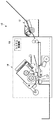
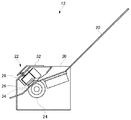
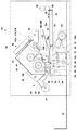
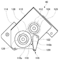
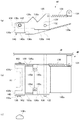
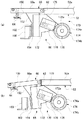
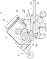
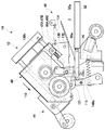
第1の実施形態に係る製本システムの正面図である。It is a front view of the bookbinding system concerning a 1st embodiment. 第1の実施形態に係る給紙装置の正面図である。1 is a front view of a sheet feeding device according to a first embodiment. 第1の実施形態に係る糊付け装置の正面図である。It is a front view of the gluing device concerning a 1st embodiment. 第1の実施形態に係る糊付けユニットの正面図である。It is a front view of the gluing unit which concerns on 1st Embodiment. (a)は、用紙押し付け機構の正面図であり、(b)は用紙押し付け機構の上面図であり、(c)は、挿入孔の形状を示す図である。(A) is a front view of the paper pressing mechanism, (b) is a top view of the paper pressing mechanism, and (c) is a diagram showing the shape of the insertion hole. (a)は、通常時の第2用紙載置台および回動機構の正面図であり、(b)は、第2用紙載置台が回動したときの第2用紙載置台および回動機構の正面図である。(A) is a front view of the 2nd paper mounting base and rotation mechanism in the normal time, (b) is the front of the 2nd paper mounting base and rotation mechanism when the 2nd paper mounting base rotates. FIG. 糊付けユニットが退避位置にあるときの糊付け装置の正面図である。It is a front view of the gluing device when the gluing unit is in the retracted position. 押し付け面が用紙に当接するまで糊付けユニットを進行させたときの糊付け装置の正面図である。It is a front view of the gluing device when the gluing unit is advanced until the pressing surface comes into contact with the paper. 糊付けローラと第2用紙載置台によって用紙の挟持が開始されたときの糊付け装置の正面図である。FIG. 10 is a front view of the gluing device when the sheet clamping is started by the gluing roller and the second sheet placing table. 用紙の挟持開始位置よりさらに糊付けユニットを進行させたときの糊付け装置の正面図である。FIG. 10 is a front view of the gluing device when the gluing unit is further advanced from the sheet nipping start position. 糊付けユニットの退避が開始され、第2用紙載置台が保持位置で保持されたときの糊付け装置の正面図である。FIG. 6 is a front view of the gluing device when retraction of the gluing unit is started and the second paper placement table is held at the holding position. 第2用紙載置台が保持位置に保持されたまま糊付けユニットをさらに退避させたときの糊付け装置の正面図である。FIG. 10 is a front view of the gluing device when the gluing unit is further retracted while the second paper placing table is held at the holding position. 図12の状態からさらに糊付けユニットを退避させたときの糊付け装置の正面図である。FIG. 13 is a front view of the gluing device when the gluing unit is further retracted from the state of FIG. 12. 第2用紙載置台の保持が解除されたときの糊付け装置の正面図である。It is a front view of a gluing device when holding of the 2nd paper mounting base is canceled. 製本システムによる製本処理の実行手順を示すフローチャートである。It is a flowchart which shows the execution procedure of the bookbinding process by a bookbinding system. 第2の実施形態に係る糊付け装置の正面図である。It is a front view of the gluing apparatus which concerns on 2nd Embodiment. 第3の実施形態に係る製本システムの正面図である。It is a front view of the bookbinding system concerning a 3rd embodiment. 第3の実施形態に係る製本システムによって作成された冊子を示す図である。It is a figure which shows the booklet produced by the bookbinding system which concerns on 3rd Embodiment. 第4の実施形態に係る製本システムの正面図である。It is a front view of the bookbinding system concerning a 4th embodiment. (a)および(b)は、第4の実施形態に係る圧着機構の構成および動作を示す図である。(A) And (b) is a figure which shows the structure and operation | movement of the crimping | compression-bonding mechanism which concern on 4th Embodiment. (a)および(b)は、第5の実施形態に係る圧着機構の構成および動作を示す図である。(A) And (b) is a figure which shows the structure and operation | movement of the crimping | compression-bonding mechanism which concern on 5th Embodiment. 第5の実施形態に係る製本システムによって作成された冊子を示す図である。It is a figure which shows the booklet produced by the bookbinding system which concerns on 5th Embodiment. (a)および(b)は、第6の実施形態に係る圧着機構の構成および動作を示す図である。(A) And (b) is a figure which shows the structure and operation | movement of the crimping | compression-bonding mechanism which concern on 6th Embodiment. 第6の実施形態に係る製本システムによって作成された冊子を示す図である。It is a figure which shows the booklet produced by the bookbinding system which concerns on 6th Embodiment. 第7の実施形態に係る製本システムの正面図である。It is a front view of the bookbinding system concerning a 7th embodiment. 図25の視点Pから切り落とし機構を見た図である。It is the figure which looked at the cutoff mechanism from the viewpoint P of FIG. 第7の実施形態に係る製本システムによって作成された冊子を示す図である。It is a figure which shows the booklet produced by the bookbinding system which concerns on 7th Embodiment. 第8の実施形態に係る糊付け装置の正面図である。It is a front view of the gluing apparatus which concerns on 8th Embodiment.

以下、図面を参照して本発明の実施の形態(以下、実施形態という)について詳細に説明する。   Hereinafter, embodiments of the present invention (hereinafter referred to as embodiments) will be described in detail with reference to the drawings.

(第1の実施形態)
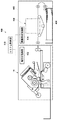
図1は、第1の実施形態に係る製本システム10の正面図である。製本システム10は、給紙装置12、糊付け装置14、およびシステム制御部16を有する。理解を容易にするため、給紙装置12、および糊付け装置14は表面のカバーの図示を省略している。
(First embodiment)
FIG. 1 is a front view of a bookbinding system 10 according to the first embodiment. The bookbinding system 10 includes a paper feeding device 12, a gluing device 14, and a system control unit 16. In order to facilitate understanding, the surface cover of the paper feeding device 12 and the gluing device 14 is not shown.

給紙装置12は、冊子に含ませるべき複数の用紙を一枚ずつ分離して糊付け装置14に送り出す。糊付け装置14は、給紙装置12から送り込まれた用紙に糊付けして冊子を作成する。システム制御部16は、各種の演算を実行するCPU、各種の制御プログラムを格納するROM、およびデータ格納やプログラム実行のためのワークエリアとして利用されるRAMを有する。システム制御部16は、給紙装置12および糊付け装置14の内部に設けられたアクチュエータの作動を制御する。   The paper feeding device 12 separates a plurality of papers to be included in the booklet one by one and sends them to the gluing device 14. The gluing device 14 creates a booklet by gluing the paper fed from the paper feeding device 12. The system control unit 16 includes a CPU that executes various calculations, a ROM that stores various control programs, and a RAM that is used as a work area for data storage and program execution. The system control unit 16 controls the operation of actuators provided inside the sheet feeding device 12 and the gluing device 14.

図2は、第1の実施形態に係る給紙装置12の正面図である。給紙装置12は、給紙トレイ20、用紙分離機構22、および筐体30を有する。給紙トレイ20は平板状に形成され、用紙搬送方向下流側(以下、「下流側」という)に進むにしたがって低くなるよう傾斜した状態で筐体30に固定されている。   FIG. 2 is a front view of the paper feeding device 12 according to the first embodiment. The sheet feeding device 12 includes a sheet feeding tray 20, a sheet separating mechanism 22, and a housing 30. The paper feed tray 20 is formed in a flat plate shape, and is fixed to the housing 30 in an inclined state so as to become lower as it proceeds downstream in the paper conveyance direction (hereinafter referred to as “downstream side”).

用紙分離機構22は、分離ローラ24、押圧部材26、および付勢部材であるコイルスプリング28を有する。分離ローラ24は給紙トレイ20の下流側端部の下方に配置される。押圧部材26はブロック状に形成され、給紙トレイ20の下流側端部の上方に配置される。筐体30は、上部に支持プレート32を有し、この支持プレート32と押圧部材26との間にコイルスプリング28が配置される。コイルスプリング28は、分離ローラ24に向かう方向への付勢力を押圧部材26に与える。押圧部材26のうち分離ローラ24に対向する個所には分離パッド34が設けられており、分離パッド34は、コイルスプリング28の付勢力により分離ローラ24に押し付けられる。   The paper separation mechanism 22 includes a separation roller 24, a pressing member 26, and a coil spring 28 that is an urging member. The separation roller 24 is disposed below the downstream end of the paper feed tray 20. The pressing member 26 is formed in a block shape and is disposed above the downstream end portion of the paper feed tray 20. The housing 30 has a support plate 32 at the top, and a coil spring 28 is disposed between the support plate 32 and the pressing member 26. The coil spring 28 applies an urging force in a direction toward the separation roller 24 to the pressing member 26. A separation pad 34 is provided at a location facing the separation roller 24 in the pressing member 26, and the separation pad 34 is pressed against the separation roller 24 by the urging force of the coil spring 28.

分離ローラ24は、伝達機構(図示せず)を介してモータ(図示せず)に接続されている。システム制御部16は、用紙を搬送するときにこのモータを回転させて分離ローラ24を回転させ、給紙トレイ20に積載された用紙のうち最下位の用紙を分離ローラ24と分離パッド34によって分離して一枚ずつ糊付け装置14に送り出す。なお、給紙装置12は、積載された用紙のうち最上位の用紙を送り出すよう設けられてもよい。また、給紙装置12は、送り出した用紙を反転させる用紙反転機構を設けてもよい。   The separation roller 24 is connected to a motor (not shown) through a transmission mechanism (not shown). The system controller 16 rotates the motor to rotate the separation roller 24 when transporting the paper, and the lowermost paper among the papers stacked on the paper feed tray 20 is separated by the separation roller 24 and the separation pad 34. Then, they are sent one by one to the gluing device 14. The paper feeding device 12 may be provided so as to send out the uppermost paper among the stacked paper. Further, the paper feeding device 12 may be provided with a paper reversing mechanism for reversing the fed paper.

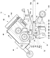
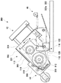
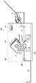
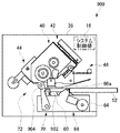
図3は、第1の実施形態に係る糊付け装置14の正面図である。糊付け装置14は、糊付けユニット40、ガイド機構42、駆動機構44、用紙押し付け機構46を備える。   FIG. 3 is a front view of the gluing device 14 according to the first embodiment. The gluing device 14 includes a gluing unit 40, a guide mechanism 42, a drive mechanism 44, and a paper pressing mechanism 46.

図4は、第1の実施形態に係る糊付けユニット40の正面図である。糊付けユニット40は、支持ブラケット110、送り出しリール112、巻き取りリール114、および糊付けヘッド116を有する。支持ブラケット110は平面部を有し、この平面状に送り出しリール112、巻き取りリール114、および糊付けヘッド116が取り付けられる。   FIG. 4 is a front view of the gluing unit 40 according to the first embodiment. The gluing unit 40 includes a support bracket 110, a feed reel 112, a take-up reel 114, and a gluing head 116. The support bracket 110 has a flat portion, and the feed reel 112, the take-up reel 114, and the gluing head 116 are attached in this flat shape.

送り出しリール112は、支持ブラケット110に回転可能に支持される。送り出しリール112には、糊シート118が予め巻回されている。糊シート118は、帯状に形成された基材シートの一方の面に糊が付着されて構成されている。この「糊」は広義の糊を意味し、各種合成樹脂系の接着剤をも含みうる。具体的には、基材シートは剥離性を有し、この基材シートに、円形や四角形からなるドット状の糊セグメントが付着している。糊セグメントは、剥離の影響を他に与えることを回避すべく、所定の間隙を空けて基材シートの幅方向および長さ方向にそれぞれ複数設けられる。   The delivery reel 112 is rotatably supported by the support bracket 110. A glue sheet 118 is wound around the delivery reel 112 in advance. The glue sheet 118 is configured such that glue is attached to one surface of a base sheet formed in a band shape. This “glue” means a paste in a broad sense, and may include various synthetic resin adhesives. Specifically, the base material sheet has peelability, and a dot-shaped paste segment made of a circle or a rectangle is attached to the base material sheet. A plurality of glue segments are provided in the width direction and the length direction of the base sheet with a predetermined gap therebetween in order to avoid other effects of peeling.

巻き取りリール114は、送り出しリール112の下流側おいて支持ブラケット110に回転可能に支持される。糊付けヘッド116は、糊付けローラ120を有する。糊付けローラ120は、送り出しリール112と巻き取りリール114との間且つこれらより下方おいて、支持ブラケット110に回転可能に支持されている。送り出しリール112の下方には、支持ブラケット110に回転可能に支持された引き回しローラ122が設けられている。送り出しリール112に巻回された糊シート118は、引き回しローラ122および糊付けローラ120に接するよう引き回され、端部が巻き取りリール114に固定される。こうして糊付けローラ120は、一方の面に糊が付着された糊シート118の糊付着面118aの裏面118bと接する。   The take-up reel 114 is rotatably supported by the support bracket 110 on the downstream side of the feed reel 112. The gluing head 116 has a gluing roller 120. The gluing roller 120 is rotatably supported by the support bracket 110 between and below the feed reel 112 and the take-up reel 114. Below the feed reel 112, a drawing roller 122 that is rotatably supported by the support bracket 110 is provided. The glue sheet 118 wound around the delivery reel 112 is drawn so as to come into contact with the drawing roller 122 and the gluing roller 120, and the end is fixed to the take-up reel 114. Thus, the gluing roller 120 is in contact with the back surface 118b of the gluing surface 118a of the gluing sheet 118 having gluing on one surface.

送り出しリール112の装置後方には、プーリ124が同軸に設けられている。巻き取りリール114の装置後方には、プーリ126が同軸に設けられている。プーリ124とプーリ126には、ベルト128がかけられている。後述するように糊付けローラ120を用紙に押し付けて糊シート118の裏面118b上を転動させて走行させると、送り出しリール112から糊シート118が送り出される。このときの送り出しリール112の駆動力がベルト128およびプーリ126を介して巻き取りリール114にも伝達し、巻き取りリール114が回転して糊シート118を巻き取る。   A pulley 124 is coaxially provided on the rear side of the delivery reel 112. A pulley 126 is provided coaxially behind the take-up reel 114. A belt 128 is hung on the pulley 124 and the pulley 126. As will be described later, when the gluing roller 120 is pressed against the sheet to roll on the back surface 118b of the gluing sheet 118 and run, the gluing sheet 118 is fed from the feed reel 112. The driving force of the delivery reel 112 at this time is also transmitted to the take-up reel 114 via the belt 128 and the pulley 126, and the take-up reel 114 rotates to take up the glue sheet 118.

なお、送り出しリール112から送り出される長さより長く糊シート118が巻き取りリール114によって巻き取られることを回避するため、所定のトルクが与えられたときプーリ126とベルト128、またはプーリ124とベルト128とが互いに摺動するよう設けられている。このため、プーリ126、プーリ124、ベルト128は、トルクリミッター機能を有する巻き取り機構としても機能する。これにより、緩みの発生を回避しつつ適切に糊シート118を巻き取り可能となっている。プーリ124には、予備送りギヤ129が同軸に固定されている。   In order to prevent the glue sheet 118 from being taken up by the take-up reel 114 longer than the length fed from the feed reel 112, the pulley 126 and the belt 128, or the pulley 124 and the belt 128 when a predetermined torque is applied. Are provided to slide relative to each other. For this reason, the pulley 126, the pulley 124, and the belt 128 also function as a winding mechanism having a torque limiter function. Thereby, the glue sheet 118 can be appropriately wound up while avoiding the occurrence of looseness. A preliminary feed gear 129 is coaxially fixed to the pulley 124.

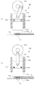
図5(a)は、用紙押し付け機構46の正面図であり、図5(b)は用紙押し付け機構46の上面図である。用紙押し付け機構46は、中継ブラケット130、回動軸132、ブラケット134、コイルスプリング136、用紙押さえ部材138、および用紙ガイド144を有する。   FIG. 5A is a front view of the paper pressing mechanism 46, and FIG. 5B is a top view of the paper pressing mechanism 46. The paper pressing mechanism 46 includes a relay bracket 130, a rotating shaft 132, a bracket 134, a coil spring 136, a paper pressing member 138, and a paper guide 144.

中継ブラケット130は、板金がコ字状に曲げられることにより、連結部130bを介して2枚の側面部130aが結合されるよう形成されている。側面部130aの各々には挿入孔130fが設けられている。回動軸132は筐体38に固定されており、この2つの挿入孔130fに挿入される。こうして中継ブラケット130は、筐体38に対して回動可能に支持される。コイルスプリング136は、一端がこのブラケット134に取り付けられ、他端が筐体38に近い側の側面部130aの上流側端部に取り付けられる。   The relay bracket 130 is formed so that the two side surface portions 130a are joined via the connecting portion 130b by bending the sheet metal into a U-shape. Each of the side portions 130a is provided with an insertion hole 130f. The rotating shaft 132 is fixed to the housing 38 and is inserted into the two insertion holes 130f. Thus, the relay bracket 130 is rotatably supported with respect to the housing 38. One end of the coil spring 136 is attached to the bracket 134 and the other end is attached to the upstream end of the side surface portion 130 a on the side close to the housing 38.

側面部130aの各々の下流側端部近傍には、ピン142が設けられている。用紙押さえ部材138は板金がコ字状に折り曲げられて形成されている。両端の折り曲げ部138aの各々には挿入孔138cが設けられており、この挿入孔138cの各々にピン142が挿入される。こうして両端の折り曲げ部138aの間の底部138bが下方に位置するよう、用紙押さえ部材138が中継ブラケット130に支持される。このとき用紙押さえ部材138は、底部138bが挿入孔138cより下方において水平となるよう支持される。   A pin 142 is provided in the vicinity of each downstream end portion of the side surface portion 130a. The sheet pressing member 138 is formed by bending a sheet metal into a U-shape. Each of the bent portions 138a at both ends is provided with an insertion hole 138c, and a pin 142 is inserted into each of the insertion holes 138c. Thus, the sheet pressing member 138 is supported by the relay bracket 130 so that the bottom portion 138b between the bent portions 138a at both ends is positioned below. At this time, the sheet pressing member 138 is supported so that the bottom portion 138b is horizontal below the insertion hole 138c.

底部138bには、下流側中央が切りかかれた切り欠き138dが設けられている。このため、底部138bはコ字状に形成される。底部138bの下面には、同様にコ字状の弾性部材140が貼り付けられている。第1の実施形態では弾性部材140はゴムによって形成されているが、弾性部材140の材料がこれに限られないことは勿論である。この弾性部材140の下面が、用紙を押し付ける押し付け面140aとなる。また、弾性部材140に代えて、例えば布類などによって形成された緩衝部材が設けられてもよい。   The bottom portion 138b is provided with a notch 138d having a downstream center cut away. For this reason, the bottom 138b is formed in a U-shape. Similarly, a U-shaped elastic member 140 is attached to the lower surface of the bottom portion 138b. In the first embodiment, the elastic member 140 is formed of rubber, but it is needless to say that the material of the elastic member 140 is not limited to this. The lower surface of the elastic member 140 serves as a pressing surface 140a that presses the paper. Moreover, it replaces with the elastic member 140, and the buffer member formed, for example with cloth etc. may be provided.

用紙押さえ部材138は、コ字状の押し付け面140aが糊転写領域R1を囲うように配置される。これにより、用紙の糊転写領域R1の用紙幅方向外側および上流側で用紙を押さえつけることが可能となり、糊シート118からの用紙の引き剥がしをより容易にすることができる。   The sheet pressing member 138 is disposed so that the U-shaped pressing surface 140a surrounds the glue transfer region R1. As a result, the sheet can be pressed on the outer side and the upstream side in the sheet width direction of the sheet glue transfer region R1, and the sheet can be more easily peeled off from the glue sheet 118.

上述のコイルスプリング136は、中継ブラケット130を時計回り方向に回動させて弾性部材140を上昇させるよう、中継ブラケット130に付勢力を与える。筐体38にはストッパ(図示せず)が設けられており、中継ブラケット130は、コイルスプリング136の付勢力によってこのストッパに当接して初期位置に保持される。   The coil spring 136 described above applies an urging force to the relay bracket 130 so as to rotate the relay bracket 130 clockwise to raise the elastic member 140. The housing 38 is provided with a stopper (not shown), and the relay bracket 130 is held in the initial position by abutting against the stopper by the urging force of the coil spring 136.

一対の側面部130aの各々には、後述するように付勢力が与えられる被押圧面130cが設けられている。中継ブラケット130は、この被押圧面130cに付勢力が与えられることにより、コイルスプリング136によって与えられる以上のトルクが与えられたときに、用紙押さえ部材138を下降させるよう回動軸132を中心に反時計回りに回動する。被押圧面130cの各々には、後述する挿入軸が挿入される挿入孔130dが設けられている。   Each of the pair of side surfaces 130a is provided with a pressed surface 130c to which an urging force is applied as will be described later. The relay bracket 130 is centered on the rotation shaft 132 so as to lower the sheet pressing member 138 when an urging force is applied to the pressed surface 130c and a torque greater than that provided by the coil spring 136 is applied. Turn counterclockwise. Each of the pressed surfaces 130c is provided with an insertion hole 130d into which an insertion shaft described later is inserted.

中継ブラケット130は、用紙搬送方向上流側(以下、「上流側」という)に進むほど上昇するよう傾斜するガイド部130eを有する。このガイド部130eの表面に、薄い板金によって形成された用紙ガイド144が固定される。こうして中継ブラケット130に向かって送り込まれた用紙は、用紙ガイド144によって押し付け面140aより下方に案内される。   The relay bracket 130 has a guide portion 130e that is inclined so as to rise as it proceeds upstream in the sheet conveyance direction (hereinafter referred to as “upstream side”). A sheet guide 144 formed of a thin sheet metal is fixed to the surface of the guide portion 130e. The sheet thus fed toward the relay bracket 130 is guided below the pressing surface 140a by the sheet guide 144.

図5(c)は、挿入孔138cの形状を示す図である。用紙押さえ部材138は、第2用紙載置面60aと用紙2の挟持を開始後、第2用紙載置台60の回動に伴って用紙2の押し付け位置を維持したまま回動する。このとき、中継ブラケット130の回転運動によってピン142が円弧状の軌跡を描きながら移動する。このため、挿入孔138cは、用紙搬送方向に延在し、また、上方が逆V型に切り欠かれた特殊孔となっている。挿入孔138cをこのような特殊孔とすることにより、用紙2を押し付けながらの回動と、ピン142の軌跡の両者に対応することが可能となる。   FIG.5 (c) is a figure which shows the shape of the insertion hole 138c. The sheet pressing member 138 rotates while maintaining the pressing position of the sheet 2 as the second sheet mounting table 60 rotates after the second sheet mounting surface 60a and the sheet 2 are nipped. At this time, the pin 142 moves while drawing an arcuate locus by the rotational movement of the relay bracket 130. For this reason, the insertion hole 138c is a special hole that extends in the paper transport direction and has an upper portion cut out in an inverted V shape. By making the insertion hole 138c such a special hole, it is possible to cope with both the rotation while pressing the paper 2 and the locus of the pin 142.

図3に戻る。ガイド機構42は、ガイドロッド88およびガイドブラケット90を有する。ガイドロッド88は、下流側に進むほど下がるよう傾斜して筐体38に固定されている。ガイドブラケット90は、このガイドロッド88と摺動可能となるよう糊付けユニット40の支持ブラケット110に固定される。これにより、ガイド機構42は、ガイドロッド88の延在方向に糊付けユニット40を案内する。   Returning to FIG. The guide mechanism 42 includes a guide rod 88 and a guide bracket 90. The guide rod 88 is fixed to the casing 38 so as to incline so as to be lowered toward the downstream side. The guide bracket 90 is fixed to the support bracket 110 of the gluing unit 40 so as to be slidable with the guide rod 88. Thereby, the guide mechanism 42 guides the gluing unit 40 in the extending direction of the guide rod 88.

駆動機構44は、クランク84およびコネクティングロッド86を有する。クランク84は円盤状に形成され、クランク84の中心から外れた部分にコネクティングロッド86の一端が回転可能に取り付けられている。コネクティングロッド86の他端は糊付けユニット40の支持ブラケット110に回転可能に取り付けられている。クランク84はモータ(図示せず)に接続されている。システム制御部16は、このモータを回転させることにより、クランク84を回転させて糊付けユニット40をガイド機構42による案内方向に移動させる。   The drive mechanism 44 has a crank 84 and a connecting rod 86. The crank 84 is formed in a disc shape, and one end of a connecting rod 86 is rotatably attached to a portion off the center of the crank 84. The other end of the connecting rod 86 is rotatably attached to the support bracket 110 of the gluing unit 40. The crank 84 is connected to a motor (not shown). The system control unit 16 rotates the motor to rotate the crank 84 and move the gluing unit 40 in the guide direction by the guide mechanism 42.

なお、このモータは、例えばステッピングモータなど、回転角度を制御可能なモータであってもよい。この場合、システム制御部16は、例えばユーザの操作入力などによって、転写する糊の糊付けローラ120の走行方向の長さを取得する。システム制御部16は、取得した転写長さの糊が用紙に転写されるようモータの回転角度を調整する。これにより、糊の転写長さを可変とすることができる。   The motor may be a motor capable of controlling the rotation angle, such as a stepping motor. In this case, the system control unit 16 acquires the length in the traveling direction of the paste roller 120 for the glue to be transferred by, for example, a user operation input. The system control unit 16 adjusts the rotation angle of the motor so that the paste having the acquired transfer length is transferred to the sheet. Thereby, the transfer length of glue can be made variable.

押し付け面140aが糊付けローラ120による糊転写個所周辺において用紙を押し付けることができるよう、押し付け面140aを支持する中継ブラケット130は糊付けローラ120の周辺に配置される。糊付けユニット40は、水平且つ用紙搬送方向と垂直な方向(以下、用紙幅方向という)に並ぶよう支持ブラケット110に固定された挿入軸47Aおよび挿入軸47Bを有する。挿入軸47Aは、挿入軸47Bよりも筐体38に近い側に配置される。挿入軸47Aは、コイルスプリング48Aに挿入されてから、中継ブラケット130のうち筐体38に近い側の被押圧面130cの挿入孔130dに挿入される。挿入軸47Bは、コイルスプリング48Bに挿入されてから、中継ブラケット130のうち筐体38から遠い側の被押圧面130cの挿入孔130dに挿入される。   The relay bracket 130 that supports the pressing surface 140 a is disposed around the gluing roller 120 so that the pressing surface 140 a can press the sheet around the glue transfer portion by the gluing roller 120. The gluing unit 40 has an insertion shaft 47A and an insertion shaft 47B fixed to the support bracket 110 so as to be aligned in a horizontal direction (hereinafter referred to as a paper width direction) perpendicular to the paper transport direction. The insertion shaft 47A is disposed closer to the housing 38 than the insertion shaft 47B. After the insertion shaft 47A is inserted into the coil spring 48A, the insertion shaft 47A is inserted into the insertion hole 130d of the pressed surface 130c on the side close to the housing 38 of the relay bracket 130. After the insertion shaft 47B is inserted into the coil spring 48B, the insertion shaft 47B is inserted into the insertion hole 130d of the pressed surface 130c on the side farther from the housing 38 of the relay bracket 130.

こうして糊付けユニット40が下方に進行すると、中継ブラケット130に設けられた一対の被押圧面130cが、それぞれコイルスプリング48Aおよびコイルスプリング48Bの付勢力によって、中継ブラケット130を反時計回りに回動させる方向に付勢力を与える。なお、第1の実施形態では、コイルスプリング48Aのバネ定数がコイルスプリング48Bのバネ定数よりも高くなるようコイルスプリング48A、48Bの各々が設けられている。上述のように、筐体38に近い側の側面部130aには、コイルスプリング136による引っ張り力が与えられている。このように筐体38に近い側のコイルスプリング48Aのバネ定数を高く設定することにより、押し付け面140aの押圧力の偏りを抑制することができる。なお、コイルスプリング48Aの長さがコイルスプリング48Bの長さよりも短く形成されていてもよい。   When the gluing unit 40 is thus moved downward, the pair of pressed surfaces 130c provided on the relay bracket 130 rotate the relay bracket 130 counterclockwise by the biasing forces of the coil spring 48A and the coil spring 48B, respectively. Giving power to. In the first embodiment, the coil springs 48A and 48B are provided so that the spring constant of the coil spring 48A is higher than the spring constant of the coil spring 48B. As described above, a tensile force by the coil spring 136 is applied to the side surface portion 130a on the side close to the housing 38. In this way, by setting the spring constant of the coil spring 48A closer to the casing 38 to be high, it is possible to suppress the bias of the pressing force on the pressing surface 140a. The length of the coil spring 48A may be shorter than the length of the coil spring 48B.

糊付け装置14は、搬入ローラ50、第1用紙載置台52、プッシャ54、第2用紙載置台60、回動機構66をさらに備える。一対の搬入ローラ50は、給紙装置12から糊付け装置14に送り込まれた用紙を、第1用紙載置台52上、および糊付けローラ120と第2用紙載置台60との間に送り込む用紙搬入機構として機能する。第2用紙載置台60は、用紙押し付け機構46の押し付け面140aおよび糊付けユニット40の糊付けローラ120の下方において上面である第2用紙載置面60aが水平となるよう配置される。第1用紙載置台52は、第2用紙載置台60の上流側において、上面である第1用紙載置面52aが第2用紙載置面60aと同一平面上に位置するよう筐体38に固定されている。第1用紙載置台52は、筐体38に対して回動不能とされている。   The gluing device 14 further includes a carry-in roller 50, a first paper placement table 52, a pusher 54, a second paper placement table 60, and a rotation mechanism 66. The pair of carry-in rollers 50 serve as a paper carry-in mechanism that feeds the paper fed from the paper feeding device 12 to the gluing device 14 onto the first paper placing table 52 and between the gluing roller 120 and the second paper placing table 60. Function. The second paper placement table 60 is arranged such that the second paper placement surface 60a as the upper surface is horizontal below the pressing surface 140a of the paper pressing mechanism 46 and the glue roller 120 of the glue unit 40. The first paper placement table 52 is fixed to the casing 38 on the upstream side of the second paper placement table 60 so that the first paper placement surface 52a, which is the upper surface, is located on the same plane as the second paper placement surface 60a. Has been. The first paper placement table 52 is not rotatable with respect to the housing 38.

第1用紙載置台52の第1用紙載置面52aには逃げ孔(図示せず)が設けられている。プッシャ54は、この逃げ孔から上方に突出するよう設けられている。プッシャ54は、用紙搬送方向に移動可能に設けられている。またプッシャ54は、ラック機構(図示せず)を介してモータに接続されている。システム制御部16は、このモータを作動させることによりプッシャ54を用紙搬送方向に移動させる。プッシャ54は、糊付けローラ120と第2用紙載置台60との間に蓄積された複数の用紙の端部を押す。プッシャ54は、糊付けローラ120と第2用紙載置台60との間に蓄積された複数の用紙の端部を揃える用紙揃え機構としても機能し、また、後述する一対の排出ローラに送り出す用紙搬出機構としても機能する。   An escape hole (not shown) is provided in the first paper placement surface 52 a of the first paper placement table 52. The pusher 54 is provided so as to protrude upward from the escape hole. The pusher 54 is provided so as to be movable in the paper transport direction. The pusher 54 is connected to the motor via a rack mechanism (not shown). The system control unit 16 operates the motor to move the pusher 54 in the paper transport direction. The pusher 54 pushes the end portions of the plurality of sheets accumulated between the gluing roller 120 and the second sheet placing table 60. The pusher 54 also functions as a sheet aligning mechanism that aligns the ends of a plurality of sheets accumulated between the gluing roller 120 and the second sheet placing table 60, and also a sheet carry-out mechanism that sends out to a pair of discharge rollers described later. Also works.

回動軸62は、一端が筐体38に直接固定され、筐体38に取り付けられた支持ブラケット64に他端が固定されている。理解を容易にするため、図3では、支持ブラケット64の外形のみを図示している。第2用紙載置台60は、上流側端部が回動軸62を中心に回動可能に筐体38に支持されている。第2用紙載置台60は、回動機構66によって通常は第2用紙載置面60aが水平となる初期位置に配置され、糊付けローラ120によって下方に押されることにより下方に向けて回動するよう設けられている。   One end of the rotating shaft 62 is directly fixed to the housing 38, and the other end is fixed to a support bracket 64 attached to the housing 38. For ease of understanding, only the outer shape of the support bracket 64 is shown in FIG. The second paper placement table 60 is supported by the housing 38 so that the upstream end can be rotated about the rotation shaft 62. The second paper placement table 60 is normally arranged at an initial position where the second paper placement surface 60a is horizontal by the rotation mechanism 66, and is rotated downward by being pushed downward by the gluing roller 120. Is provided.

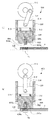
図6(a)は、通常時の第2用紙載置台60および回動機構66の正面図である。回動機構66は、コイルスプリング150、ブラケット152、位置決めブラケット160、およびブレーキ機構170を有する。付勢部材であるコイルスプリング150は、第2用紙載置台60に上方に回動するよう付勢力を与える。ブラケット152は第2用紙載置台60の下面に取り付けられており、下流側の面にゴムによって成形された緩衝部材154が貼り付けられている。位置決めブラケット160は筐体38に固定されており、上流側の面にゴムによって成形された緩衝部材162が貼り付けられている。   FIG. 6A is a front view of the second sheet mounting table 60 and the rotation mechanism 66 in a normal state. The rotation mechanism 66 includes a coil spring 150, a bracket 152, a positioning bracket 160, and a brake mechanism 170. The coil spring 150, which is an urging member, applies an urging force to the second paper placing table 60 so as to rotate upward. The bracket 152 is attached to the lower surface of the second paper placing table 60, and a buffer member 154 formed of rubber is attached to the downstream surface. The positioning bracket 160 is fixed to the housing 38, and a cushioning member 162 made of rubber is attached to the upstream surface.

ブラケット152および位置決めブラケット160は、緩衝部材154および緩衝部材162を介してブラケット152が位置決めブラケット160に当接したときに第2用紙載置面60aが水平となるよう第2用紙載置台60を位置決めする。以下、第2用紙載置面60aが水平となるときの第2用紙載置台60の位置を「初期位置」という。コイルスプリング150は、第2用紙載置台60に対し上方への付勢力を与えることにより、ブラケット152を位置決めブラケット160に突き当てて、第2用紙載置台60を初期位置に保持する。   The bracket 152 and the positioning bracket 160 position the second paper placement table 60 so that the second paper placement surface 60a is horizontal when the bracket 152 comes into contact with the positioning bracket 160 via the cushioning member 154 and the cushioning member 162. To do. Hereinafter, the position of the second paper placement table 60 when the second paper placement surface 60a is horizontal is referred to as an “initial position”. The coil spring 150 applies an upward urging force to the second paper placement table 60, thereby abutting the bracket 152 against the positioning bracket 160 and holding the second paper placement table 60 in the initial position.

ブレーキ機構170は、プレート172、回転軸174、支持ブロック176、ロッド178、およびコイルスプリング179を有する。プレート172は、ブラケット152に固定されている。プレート172には、ギヤ部172aが設けられている。回転軸174は、回転可能に筐体38に支持されている。回転軸174の外周にはギヤ部174aが設けられており、このギヤ部174aがプレート172のギヤ部172aと噛み合っている。   The brake mechanism 170 includes a plate 172, a rotating shaft 174, a support block 176, a rod 178, and a coil spring 179. The plate 172 is fixed to the bracket 152. The plate 172 is provided with a gear portion 172a. The rotating shaft 174 is rotatably supported by the housing 38. A gear portion 174 a is provided on the outer periphery of the rotating shaft 174, and the gear portion 174 a meshes with the gear portion 172 a of the plate 172.

支持ブロック176は、支持ブラケット64を介して筐体38に固定されている。支持ブラケット64にはロッド178が摺動可能に挿入される挿入孔が設けられており、この挿入孔にコイルスプリング179とロッド178が挿入される。ロッド178は、コイルスプリングによって付勢力が与えられ、回転軸174の外周面である被押圧面174bに押し付けられている。   The support block 176 is fixed to the housing 38 via the support bracket 64. The support bracket 64 is provided with an insertion hole into which the rod 178 is slidably inserted. The coil spring 179 and the rod 178 are inserted into the insertion hole. The rod 178 is biased by a coil spring and is pressed against the pressed surface 174b which is the outer peripheral surface of the rotating shaft 174.

なお、ギヤ部174aと被押圧面174bとの間にはワンウェイベアリングが設けられている。このため、第2用紙載置台60が上方に退避するときは、被押圧面174bがギヤ部174aと共に回転し、被押圧面174bとロッド178との間に摩擦力が生じる。一方、第2用紙載置台60が下方に進行するときは被押圧面174bが回転せず、被押圧面174bとロッド178との間の摩擦力の発生を回避している。これにより、第2用紙載置台60の保持解除による衝撃を緩和しつつ、第2用紙載置台60の下方への円滑な回動を実現している。   A one-way bearing is provided between the gear portion 174a and the pressed surface 174b. For this reason, when the second paper placing table 60 is retracted upward, the pressed surface 174b rotates together with the gear portion 174a, and a frictional force is generated between the pressed surface 174b and the rod 178. On the other hand, when the second paper placement table 60 advances downward, the pressed surface 174b does not rotate, and the generation of frictional force between the pressed surface 174b and the rod 178 is avoided. Accordingly, the second paper placement table 60 can be smoothly rotated downward while alleviating the impact caused by releasing the holding of the second paper placement table 60.

図6(b)は、第2用紙載置台60が回動したときの第2用紙載置台60および回動機構66の正面図である。後述するように糊付けローラ120によって第2用紙載置面60aが下方に押し付けられると、第2用紙載置台60が回動軸62を中心に下方に回動する。これによりブラケット152とともにプレート172も回動し、回転軸174が回転する。このとき、回転軸174の外周面とロッド178の端面との間に摩擦力が発生し、第2用紙載置台60の回動速度を緩める。   FIG. 6B is a front view of the second paper placement table 60 and the rotation mechanism 66 when the second paper placement table 60 is rotated. As will be described later, when the second paper placement surface 60 a is pressed downward by the gluing roller 120, the second paper placement base 60 rotates downward about the rotational shaft 62. As a result, the plate 172 also rotates together with the bracket 152, and the rotation shaft 174 rotates. At this time, a frictional force is generated between the outer peripheral surface of the rotating shaft 174 and the end surface of the rod 178, and the rotational speed of the second paper mounting table 60 is reduced.

第2用紙載置台60は、後述するように所定の保持位置で一旦保持され、その後保持が解除されコイルスプリング150の付勢力によって初期位置に向けて回動する。このようにブレーキ機構170を設けることによって、コイルスプリング150が初期位置に戻るときにブラケット152が位置決めブラケット160に突き当たる衝撃を緩和することができる。   As will be described later, the second sheet placing table 60 is temporarily held at a predetermined holding position, and then the holding is released, and the second sheet placing table 60 is rotated toward the initial position by the biasing force of the coil spring 150. By providing the brake mechanism 170 in this manner, it is possible to mitigate the impact of the bracket 152 hitting the positioning bracket 160 when the coil spring 150 returns to the initial position.

図3に戻る。糊付け装置14は、保持機構70および保持解除機構72をさらに備える。保持機構70は、ラッチピン61、ラッチ部材92、回動軸94、およびコイルスプリング96を有する。ラッチピン61は、第2用紙載置台60の下流側端部に設けられている。回動軸94は、このラッチピン61の下方において筐体38に取り付けられている。ラッチ部材92は、回動軸94によって回動可能に支持されている。ラッチ部材92は、先端が鉤状になるよう凹む係止部92aが設けられている。ラッチ部材92は、係止部92aが上流側を向くようラッチピン61の下流側に配置される。ラッチ部材92は、第2用紙載置台60が初期位置にあるときは係止部92aとラッチピン61との係止が解除され、第2用紙載置台60が下方に回動したときに係止部92aがラッチピン61に係止されるよう設けられる。   Returning to FIG. The gluing device 14 further includes a holding mechanism 70 and a holding release mechanism 72. The holding mechanism 70 includes a latch pin 61, a latch member 92, a rotation shaft 94, and a coil spring 96. The latch pin 61 is provided at the downstream end of the second paper placement table 60. The rotating shaft 94 is attached to the housing 38 below the latch pin 61. The latch member 92 is rotatably supported by a rotation shaft 94. The latch member 92 is provided with a locking portion 92a that is recessed so that the tip has a bowl shape. The latch member 92 is disposed on the downstream side of the latch pin 61 so that the locking portion 92a faces the upstream side. The latch member 92 is unlocked when the second paper placing table 60 is in the initial position, and the latching portion 92a and the latch pin 61 are unlocked and the second paper placing table 60 is rotated downward. 92 a is provided to be latched to the latch pin 61.

コイルスプリング96は引っ張りバネであり、一端がラッチ部材92に取り付けられ、他端が筐体38に取り付けられている。コイルスプリング96は、上流側に回動させるようラッチ部材92に付勢力を与える。このコイルスプリング96の付勢力によって、第2用紙載置台60がある位置まで回動すると、コイルスプリング96の付勢力によってラッチ部材92の係止部92aにラッチピン61が係止される。   The coil spring 96 is a tension spring, and one end is attached to the latch member 92 and the other end is attached to the housing 38. The coil spring 96 applies an urging force to the latch member 92 so as to rotate upstream. When the second paper placement table 60 is rotated to a certain position by the biasing force of the coil spring 96, the latch pin 61 is locked to the locking portion 92a of the latch member 92 by the biasing force of the coil spring 96.

保持解除機構72は、揺動プレート98、揺動軸100、第1ピン102、第2ピン104を有する。揺動軸100は筐体38取り付けられている。揺動プレート98は細長い板状に形成されており、中央部が揺動軸100に回動可能に支持されている。第1ピン102は、糊付けユニット40の支持ブラケット110に取り付けられている。第2ピン104は、ラッチ部材92に取り付けられている。   The holding release mechanism 72 includes a swing plate 98, a swing shaft 100, a first pin 102, and a second pin 104. The swing shaft 100 is attached to the housing 38. The swing plate 98 is formed in a long and narrow plate shape, and a central portion is rotatably supported by the swing shaft 100. The first pin 102 is attached to the support bracket 110 of the gluing unit 40. The second pin 104 is attached to the latch member 92.

糊付けユニット40が下方に進出してからある位置まで上方に退避すると、第1ピン102が揺動プレート98の上方の端部近傍に当接し、さらに糊付けユニット40が退避すると、第1ピン102によってその端部が押されて揺動プレート98が回動する。この回動によって揺動プレート98の下方の端部近傍が第2ピン104を下流側に押す。これにより、ラッチ部材92が下流側に回動して係止部92aがラッチピン61から外され、係止状態が解除される。このように保持機構70は、糊付けローラ120が所定位置まで退避したときに、その退避動作に連動して第2用紙載置台60の保持を解除する。   When the gluing unit 40 advances downward to a certain position and retreats upward, the first pin 102 comes into contact with the vicinity of the upper end of the swing plate 98, and when the gluing unit 40 retreats, the first pin 102 The end is pushed and the swing plate 98 is rotated. By this rotation, the vicinity of the lower end of the swing plate 98 pushes the second pin 104 downstream. As a result, the latch member 92 rotates downstream, the locking portion 92a is removed from the latch pin 61, and the locked state is released. As described above, when the gluing roller 120 is retracted to a predetermined position, the holding mechanism 70 releases the holding of the second sheet placing table 60 in conjunction with the retracting operation.

糊付け装置14は、ストッパ74、排出ローラ80、および排出トレイ82をさらに備える。ストッパ74は、第2用紙載置台60の下流側端部近傍において、第2用紙載置面60aよりも上方に進出可能に設けられている。ストッパ74は、ソレノイド(図示せず)に接続されており、ソレノイドがオンにされることによって第2用紙載置面60aよりも上方に進出し、ソレノイドがオフにされることによって第2用紙載置面60aよりも下方に退避する。ストッパ74は、第2用紙載置面60aよりも上方に進出したときには、糊付けローラ120と第2用紙載置台60との間に送り込まれた用紙の端部が当接する。   The gluing device 14 further includes a stopper 74, a discharge roller 80, and a discharge tray 82. The stopper 74 is provided in the vicinity of the downstream end portion of the second paper placement table 60 so as to be able to advance above the second paper placement surface 60a. The stopper 74 is connected to a solenoid (not shown). When the solenoid is turned on, the stopper 74 advances above the second paper placement surface 60a. When the solenoid is turned off, the second paper placement is performed. Retreat below the placement surface 60a. When the stopper 74 advances above the second paper placement surface 60a, the end of the paper fed between the gluing roller 120 and the second paper placement base 60 comes into contact.

製本処理を実行する場合、一対の搬入ローラ50は、作成する冊子に含ませるべき用紙を糊付けローラ120と第2用紙載置台60との間に送り込んだ後、作成する冊子に含ませるべき次の用紙を、すでに送り込まれた用紙と糊付けローラ120との間に送り込む。駆動機構44は、送り込まれた用紙の端部がストッパ74に当接するたびに、その用紙に糊を転写させるよう糊付けローラ120を進行させる。なお、後述するように、駆動機構44は、冊子に含ませる最終用紙には糊の転写を回避すべく、その作動を回避する。   When the bookbinding process is executed, the pair of carry-in rollers 50 sends a sheet to be included in the booklet to be created between the gluing roller 120 and the second sheet placing table 60 and then includes the next sheet to be included in the booklet to be created. The sheet is fed between the already fed sheet and the gluing roller 120. The driving mechanism 44 advances the gluing roller 120 so that the glue is transferred to the paper every time the end of the fed paper comes into contact with the stopper 74. As will be described later, the drive mechanism 44 avoids the operation to avoid transfer of glue to the final paper included in the booklet.

こうして、糊付け装置14によって、隣接する用紙同士の少なくとも一方に糊が転写された複数の用紙が第1用紙載置面52aおよび第2用紙載置面60aに積載された状態となる。この複数の用紙は、一対の排出ローラ80によって糊付けされた個所が圧着して綴じられる。このため一対の排出ローラ80は、少なくとも一方に糊が転写された複数の用紙を挟持して圧着させる圧着処理を実行する圧着機構として機能する。   Thus, a plurality of sheets with glue transferred to at least one of adjacent sheets are stacked on the first sheet placement surface 52a and the second sheet placement surface 60a by the gluing device 14. The plurality of sheets are bound together by crimping the portions glued by the pair of discharge rollers 80. For this reason, the pair of discharge rollers 80 function as a pressure-bonding mechanism that executes a pressure-bonding process that sandwiches and press-bonds a plurality of sheets with glue transferred to at least one of them.

以下、図7〜図10に関連して、まず糊付けユニット40が進行するときの糊付け装置14の動作について詳細に説明する。また、図11〜図14に関連して、糊付けユニット40が退避するときの糊付け装置14の動作について詳細に説明する。   Hereinafter, the operation of the gluing device 14 when the gluing unit 40 proceeds will be described in detail with reference to FIGS. The operation of the gluing device 14 when the gluing unit 40 is retracted will be described in detail with reference to FIGS.

図7は、糊付けユニット40が退避位置にあるときの糊付け装置14の正面図である。退避位置とは、糊付けユニット40が最も上方に退避したときの位置をいう。このとき、第2用紙載置面60aは水平となっており、また、押し付け面140aおよび糊付けローラ120は、第2用紙載置面60aから離間している。なお、第1用紙載置面52aおよび第2用紙載置面60aには用紙2が載置されているものとする。以下、退避位置から糊付けユニット40を下降させることを「進行」という。   FIG. 7 is a front view of the gluing device 14 when the gluing unit 40 is in the retracted position. The retracted position refers to a position when the gluing unit 40 is retracted to the uppermost position. At this time, the second paper placement surface 60a is horizontal, and the pressing surface 140a and the gluing roller 120 are separated from the second paper placement surface 60a. It is assumed that the paper 2 is placed on the first paper placement surface 52a and the second paper placement surface 60a. Hereinafter, lowering the gluing unit 40 from the retracted position is referred to as “progress”.

図8は、押し付け面140aが用紙2に当接するまで糊付けユニット40を進行させたときの糊付け装置14の正面図である。図7の状態から駆動機構44を作動させると、糊付けユニット40がガイド機構42によって案内されながら下降する。これにより、中継ブラケット130の2つの被押圧面130cがそれぞれコイルスプリング48A、48Bによって押され、中継ブラケット130が回動を開始する。   FIG. 8 is a front view of the gluing device 14 when the gluing unit 40 is advanced until the pressing surface 140a comes into contact with the paper 2. When the drive mechanism 44 is operated from the state of FIG. 7, the gluing unit 40 is lowered while being guided by the guide mechanism 42. As a result, the two pressed surfaces 130c of the relay bracket 130 are pressed by the coil springs 48A and 48B, respectively, and the relay bracket 130 starts to rotate.

コイルスプリング150の付勢力に比べ、コイルスプリング48A、48Bの付勢力は弱く設定されている。このため、押し付け面140aが第2用紙載置面60a上の用紙2に接するまで中継ブラケット130が回動すると、さらに糊付けユニット40が進行しても中継ブラケット130は一旦回動を停止する。   Compared with the urging force of the coil spring 150, the urging forces of the coil springs 48A and 48B are set weaker. For this reason, when the relay bracket 130 rotates until the pressing surface 140a contacts the paper 2 on the second paper placement surface 60a, the relay bracket 130 temporarily stops rotating even if the pasting unit 40 further advances.

図9は、糊付けローラ120と第2用紙載置台60によって用紙の挟持が開始されたときの糊付け装置14の正面図である。図8の状態からさらに糊付けユニット40を進行させると、糊付けローラ120と第2用紙載置台60による用紙2の挟持が開始する。このように駆動機構44は、糊付けローラ120および第2用紙載置台60がそれらの間に送り込まれた用紙を挟持するよう糊付けローラ120を進行させる。したがって第2用紙載置台60は、糊付けローラ120と共にそれらの間に送り込まれた用紙を挟持する挟持部材として機能し、第2用紙載置面60aは挟持面として機能する。   FIG. 9 is a front view of the gluing device 14 when the clamping of the sheet is started by the gluing roller 120 and the second sheet placing table 60. When the gluing unit 40 is further advanced from the state of FIG. 8, the holding of the sheet 2 by the gluing roller 120 and the second sheet placing table 60 starts. In this way, the drive mechanism 44 advances the glue roller 120 so that the glue roller 120 and the second sheet placing table 60 sandwich the sheet fed therebetween. Therefore, the second paper placement table 60 functions as a sandwiching member that sandwiches the paper fed between them together with the gluing roller 120, and the second paper placement surface 60a functions as a sandwiching surface.

図10は、用紙の挟持開始位置よりさらに糊付けユニット40を進行させたときの糊付け装置14の正面図である。糊付けローラ120は、用紙の挟持開始後さらに進行したときに、第2用紙載置台60との間に互いに発生する抗力によって第2用紙載置台60の表面に沿って糊シート118の裏面118b上を走行するよう設けられる。   FIG. 10 is a front view of the gluing device 14 when the gluing unit 40 is further advanced from the sheet nipping start position. The glue roller 120 moves on the back surface 118b of the glue sheet 118 along the surface of the second paper placement table 60 by the drag generated between the second paper placement table 60 when it further proceeds after the start of paper clamping. Provided to travel.

具体的には、糊付けローラ120は、用紙の挟持開始後さらに進行したときに、第2用紙載置台60に与える抗力によって初期位置から付勢部材の付勢力に抗して第2用紙載置台60を回動させる。これによって糊付けローラ120は、第2用紙載置台60の表面に沿って糊シート118の裏面118b上を転動しながら用紙搬送方向に走行する。このように駆動機構44は、用紙の挟持開始後さらに糊付けローラ120を進行させることにより、糊シート118の裏面118b上を糊付けローラ120に走行させて糊シート118の糊付着面118aを用紙に押し付け、用紙に糊を転写させる。   Specifically, the glue roller 120 further resists the urging force of the urging member from the initial position by the drag force applied to the second sheet placing table 60 when it further proceeds after the start of the sheet clamping. Rotate. As a result, the gluing roller 120 travels in the sheet conveying direction while rolling on the back surface 118b of the glue sheet 118 along the surface of the second sheet placing table 60. As described above, the drive mechanism 44 further advances the glue roller 120 after starting the clamping of the paper, thereby causing the glue roller 120 to run on the back surface 118b of the glue sheet 118 and pressing the glue adhesion surface 118a of the glue sheet 118 against the paper. Transfer the glue to the paper.

このように糊付けローラ120を走行させることによって、用紙へ糊シート118を押し付ける押し付け力を確保しつつ用紙に糊を広い範囲で転写させることができる。また、第1の実施形態では、糊付けユニット40をガイド機構42の案内方向に進行させるだけで糊付けローラ120を用紙搬送方向に走行させることができる。このため、駆動機構44とは別に糊付けローラ120を用紙搬送方向に移動させるための駆動機構を設ける場合に比べ、装置の構成を簡素にすることができる。   By running the gluing roller 120 in this way, the gluing can be transferred onto the paper in a wide range while ensuring the pressing force to press the gluing sheet 118 onto the paper. In the first embodiment, the gluing roller 120 can be caused to travel in the paper transport direction by simply moving the gluing unit 40 in the guide direction of the guide mechanism 42. For this reason, compared with the case where the drive mechanism for moving the glue roller 120 in the paper conveyance direction is provided separately from the drive mechanism 44, the configuration of the apparatus can be simplified.

また、ガイド機構42は、第2用紙載置台60が初期位置にあるときの第2用紙載置面60aに、第2用紙載置台60の回動軸62から離間するほど近づくよう傾斜する方向に糊付けローラ120を案内する。駆動機構44は、ガイド機構42の案内方向に糊付けローラ120を進行させる。このように傾斜した方向に糊付けローラ120を進行させることによって、例えば垂直に糊付けローラ120を進行させる場合に比べ、用紙2を挟持しながら糊付けローラ120が走行する距離を長くすることができる。このため、糊付けユニット40の鉛直方向のストローク量を抑制しつつ用紙に糊を広い範囲で転写することができる。糊付けユニット40が最も下方に進行すると、ラッチ部材92が微小に回動して第2用紙載置台60のラッチピン61がラッチ部材92の係止部92aに収容される。   The guide mechanism 42 is inclined in such a direction that the guide mechanism 42 approaches the second paper placement surface 60a when the second paper placement table 60 is in the initial position as the guide mechanism 42 is separated from the rotation shaft 62 of the second paper placement table 60. The gluing roller 120 is guided. The drive mechanism 44 advances the glue roller 120 in the guide direction of the guide mechanism 42. By advancing the gluing roller 120 in such an inclined direction, for example, the distance traveled by the gluing roller 120 while holding the paper 2 can be increased as compared with the case where the gluing roller 120 is moved vertically. For this reason, it is possible to transfer the glue to the paper in a wide range while suppressing the vertical stroke amount of the glue unit 40. When the gluing unit 40 advances to the lowermost position, the latch member 92 is slightly rotated, and the latch pin 61 of the second paper placement table 60 is accommodated in the engaging portion 92a of the latch member 92.

図11は、糊付けユニット40の退避が開始され、第2用紙載置台60が保持位置で保持されたときの糊付け装置14の正面図である。糊付けユニット40を最も下方に進行させると、駆動機構44は、次に用紙の挟持を解除させるよう糊付けローラ120を上方に退避させる。駆動機構44によって糊付けユニット40が上方に微小に退避すると、ラッチピン61が係止部92aに係止され、第2用紙載置台60がその位置で保持される。保持位置とは、ラッチピン61が係止部92aで係止されたときの第2用紙載置台60の位置をいう。こうして保持機構70は、糊付けローラ120が退避するときに保持位置で第2用紙載置台60を保持する。   FIG. 11 is a front view of the gluing device 14 when the retraction of the gluing unit 40 is started and the second paper placing table 60 is held at the holding position. When the gluing unit 40 is advanced to the lowest position, the drive mechanism 44 next retracts the gluing roller 120 so as to release the nipping of the sheet. When the gluing unit 40 is slightly retracted upward by the drive mechanism 44, the latch pin 61 is locked to the locking portion 92a, and the second paper placement table 60 is held at that position. The holding position refers to the position of the second paper mounting table 60 when the latch pin 61 is locked by the locking portion 92a. Thus, the holding mechanism 70 holds the second paper placing table 60 at the holding position when the gluing roller 120 is retracted.

図12は、第2用紙載置台60が保持位置に保持されたまま糊付けユニット40をさらに退避させたときの糊付け装置14の正面図である。このとき、第2用紙載置台60は保持機構70によって保持位置に保持されているため糊付けローラ120が第2用紙載置面60aから離れていく。このとき用紙押さえ部材138は、糊シート118から用紙を剥がすよう、保持位置に保持された第2用紙載置台60に用紙を押さえつける。こうして糊シート118の糊付着面118aから用紙2が引き剥がされる。   FIG. 12 is a front view of the gluing device 14 when the gluing unit 40 is further retracted while the second paper placement table 60 is held at the holding position. At this time, since the second paper placement table 60 is held at the holding position by the holding mechanism 70, the gluing roller 120 moves away from the second paper placement surface 60a. At this time, the sheet pressing member 138 presses the sheet against the second sheet placing table 60 held at the holding position so as to peel the sheet from the glue sheet 118. In this way, the sheet 2 is peeled off from the glue adhering surface 118 a of the glue sheet 118.

図13は、図12の状態からさらに糊付けユニット40を退避させたときの糊付け装置14の正面図である。このとき、押し付け面140aが用紙2から離間し、用紙2への押し付けが解除される。   FIG. 13 is a front view of the gluing device 14 when the gluing unit 40 is further retracted from the state of FIG. At this time, the pressing surface 140a is separated from the paper 2 and the pressing on the paper 2 is released.

図14は、第2用紙載置台60の保持が解除されたときの糊付け装置14の正面図である。保持が解除されると、第2用紙載置台60はコイルスプリング150の付勢力によって初期位置まで回動する。このときブレーキ機構170は、第2用紙載置台60が保持位置から初期位置へ戻るときの第2用紙載置台60の移動速度を緩める緩衝手段として機能する。   FIG. 14 is a front view of the gluing device 14 when the holding of the second paper placing table 60 is released. When the holding is released, the second sheet placing table 60 is rotated to the initial position by the biasing force of the coil spring 150. At this time, the brake mechanism 170 functions as a buffer unit that reduces the moving speed of the second paper placement table 60 when the second paper placement table 60 returns from the holding position to the initial position.

糊付けユニット40が最も上方に退避するとき、予備送りギヤ129が予備送りプレート180に当接し、予備送りギヤ129が小さい角度で回転する。こうして送り出しリール112によって糊シート118が送られ、同時に送った分の糊シート118が巻き取りリール114によって巻き取られる。このように予備送りギヤ129および予備送りプレート180は、糊付けローラ120および第2用紙載置台60が用紙を挟持してから次に用紙を挟持するまでの間に、糊シート118のうち糊付けローラ120に当接する部分の糊付着面118aに糊が未転写の部分が含まれるよう糊シート118を予備的に送る。したがって予備送りギヤ129および予備送りプレート180は、糊シート118を予備的に送る予備送り機構として機能する。   When the gluing unit 40 is retracted to the uppermost position, the preliminary feed gear 129 contacts the preliminary feed plate 180, and the preliminary feed gear 129 rotates at a small angle. In this way, the paste sheet 118 is fed by the feed reel 112, and the paste sheet 118 that has been fed simultaneously is taken up by the take-up reel 114. Thus, the preliminary feeding gear 129 and the preliminary feeding plate 180 are used for the pasting roller 120 in the pasting sheet 118 between the time when the gluing roller 120 and the second paper placing table 60 hold the paper and the time when the paper is held next. The glue sheet 118 is preliminarily sent so that the part to which the glue is not transferred is included in the glue adhering surface 118a of the part in contact with the sheet. Therefore, the preliminary feeding gear 129 and the preliminary feeding plate 180 function as a preliminary feeding mechanism that preliminarily feeds the paste sheet 118.

糊シート118の糊付着面118aを用紙に押し付けた後、糊シート118を用紙から剥がすと、糊シート118は糊が転写されるためその部分の粘着力が低下する。このまま次の用紙に糊シート118を押し付けて糊付けローラ120を糊シート118の裏面上を走行させようとすると、用紙と糊シート118との間の摩擦力が低下して糊付けローラ120とともに糊シート118が移動する可能性がある。このように糊シート118が糊付けローラ120と共に移動すると、糊シート118の糊転写済みの表面が用紙上を摺動するだけで糊シート118の糊未転写部分を用紙に押し付けることが困難となる。   If the glue sheet 118 is peeled from the paper after the glue adhesion surface 118a of the glue sheet 118 is pressed against the paper, the glue is transferred to the glue sheet 118, and the adhesive strength of that portion is reduced. If the glue sheet 118 is pressed against the next sheet as it is and the glue roller 120 tries to run on the back surface of the glue sheet 118, the frictional force between the sheet and the glue sheet 118 is reduced, and the glue sheet 118 together with the glue roller 120. May move. When the glue sheet 118 moves together with the glue roller 120 in this way, it becomes difficult to press the glue-untransferred portion of the glue sheet 118 against the sheet only by sliding the glue-transferred surface of the glue sheet 118 on the sheet.

このように予備送りギヤ129および予備送りプレート180を設けることによって、糊シート118のうち糊が未転写の部分を用紙にまず押し付けることができるため、糊シート118と用紙との間の摩擦力を確保することができる。このため、糊付けローラ120を走行させるときに糊シート118が紙面上を滑って糊が転写されない事態を回避でき、糊付けローラ120に糊シート118の裏面上を良好に走行させることができる。   By providing the preliminary feeding gear 129 and the preliminary feeding plate 180 in this manner, the portion of the glue sheet 118 to which the glue has not been transferred can be first pressed against the paper, so that the frictional force between the glue sheet 118 and the paper is reduced. Can be secured. For this reason, it is possible to avoid a situation in which the glue sheet 118 slides on the paper surface and the glue is not transferred when the glue roller 120 is run, and the glue roller 120 can run on the back surface of the glue sheet 118 satisfactorily.

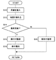
図15は、製本システム10による製本処理の実行手順を示すフローチャートである。製本システム10にはコントロールパネル(図示せず)が設けられており、ユーザは、このコントロールパネルを使って、作成したい冊子の数、冊子に含ませる用紙の枚数を入力することができる。システム制御部16は、こうして入力された冊子の数および冊子に含ませる用紙の枚数を取得する。また、製本システム10にはスタートボタン(図示せず)が設けられている。システム制御部16は、このスタートボタンの操作入力を、冊子を作成する製本要求として取得する。したがってシステム制御部16は、製本要求取得部としても機能する。   FIG. 15 is a flowchart showing the execution procedure of the bookbinding process by the bookbinding system 10. The bookbinding system 10 is provided with a control panel (not shown), and the user can use this control panel to input the number of booklets to be created and the number of sheets to be included in the booklet. The system control unit 16 acquires the number of booklets input in this way and the number of sheets included in the booklet. The bookbinding system 10 is provided with a start button (not shown). The system control unit 16 acquires the operation input of the start button as a bookbinding request for creating a booklet. Therefore, the system control unit 16 also functions as a bookbinding request acquisition unit.

本フローチャートにおける処理は、システム制御部16が製本要求を取得したときに開始し、入力された冊子の数の作成が終了するまで、またはジャムなどのエラーが発生するまで繰り返し実行される。   The processing in this flowchart is started when the system control unit 16 acquires a bookbinding request, and is repeatedly executed until creation of the number of input booklets is completed or an error such as a jam occurs.

給紙装置12は糊付け装置14に用紙を送り出し、一対の搬入ローラ50は、糊付けローラ120と第2用紙載置台60との間に用紙を搬入する(S10)。すでに第2用紙載置台60に用紙が積載されている場合、一対の搬入ローラ50は、その最上位の用紙と糊付けローラ120との間に用紙を搬入する。   The paper feeding device 12 feeds the paper to the gluing device 14, and the pair of carry-in rollers 50 carries the paper between the gluing roller 120 and the second paper placing table 60 (S10). When a sheet is already stacked on the second sheet placing table 60, the pair of carry-in rollers 50 carries the sheet between the uppermost sheet and the gluing roller 120.

用紙が搬入されると、システム制御部16は、プッシャ54を下流側に移動させて用紙の端部を揃える(S12)。一方、システム制御部16は、給紙装置12から用紙を送り出すたびに用紙枚数をカウントし、そのカウント値が、冊子に含ませるべき用紙枚数に達したか否かを判定することにより、その用紙が冊子に含ませるべき最終用紙か否かを判定する(S14)。最終用紙でない場合(S14のN)、駆動機構44は、糊付けユニット40を下方に進行させて用紙に糊シート118の糊を転写する糊付け処理を実行する(S20)。   When the paper is carried in, the system control unit 16 moves the pusher 54 to the downstream side and aligns the edges of the paper (S12). On the other hand, the system control unit 16 counts the number of sheets each time the sheet is fed from the sheet feeding device 12, and determines whether or not the counted value has reached the number of sheets to be included in the booklet. Is the last sheet to be included in the booklet (S14). If it is not the final sheet (N in S14), the drive mechanism 44 advances the gluing unit 40 downward and executes a gluing process to transfer the glue of the glue sheet 118 onto the paper (S20).

最終用紙の場合(S14のY)、駆動機構44は、最終用紙への糊の転写を回避すべく糊付けローラ120の進行を回避し(S16)、プッシャ54は、糊付けローラ120と第2用紙載置台60との間に蓄積された複数の用紙を一対の排出ローラ80に送り出す。(S18)。一対の排出ローラ80は、送り込まれた複数の用紙に圧着処理を実行する。こうして作成された冊子は、排出トレイ82に排出され蓄積される。   In the case of the final sheet (Y in S14), the drive mechanism 44 avoids the progress of the glue roller 120 to avoid transfer of glue to the final sheet (S16), and the pusher 54 is loaded with the glue roller 120 and the second sheet. A plurality of sheets accumulated between the table 60 are sent to a pair of discharge rollers 80. (S18). The pair of discharge rollers 80 performs a pressure-bonding process on the plurality of fed sheets. The booklet created in this way is discharged to the discharge tray 82 and stored.

なお、給紙装置12に、給紙トレイ20に用紙が積載されたことを検知する用紙センサが設けられてもよい。この場合、システム制御部16は、給紙トレイ20への用紙の積載が検知されたとき、その検知を製本要求として取得する。システム制御部16は、給紙トレイ20から最下位の用紙を順次送り出して糊付けするよう製本システム10を制御し、給紙トレイ20から用紙を送り出したときに給紙トレイ20上に用紙が検知されなくなった場合、その用紙を最終用紙と判定し、その用紙への糊の転写を回避するよう糊付け装置14を制御する。   The paper feeding device 12 may be provided with a paper sensor that detects that paper is stacked on the paper feeding tray 20. In this case, the system control unit 16 acquires the detection as a bookbinding request when the paper stacking on the paper feed tray 20 is detected. The system control unit 16 controls the bookbinding system 10 so as to sequentially feed and paste the lowest sheet from the sheet feeding tray 20, and when the sheet is fed from the sheet feeding tray 20, the sheet is detected on the sheet feeding tray 20. When there is no more paper, the paper is determined as the final paper, and the gluing device 14 is controlled so as to avoid transfer of glue onto the paper.

また、最下位の用紙の下面の所定位置の画像を撮像するイメージセンサが設けられていてもよい。システム制御部16は、イメージセンサによって撮像され生成された画像データを取得し、最終用紙であることを示す画像が用紙に付されているか否かを判定してもよい。システム制御部16は、最終用紙であることを示す画像が用紙に付されていると判定した場合に、その用紙を最終用紙として判定し、その用紙への糊の転写を回避するよう糊付け装置14を制御してもよい。このように用紙枚数の入力やスタートボタンの操作入力によらなくても、給紙トレイ20に用紙を積載するだけで冊子の作成を開始することができる。   In addition, an image sensor that captures an image of a predetermined position on the lower surface of the lowermost sheet may be provided. The system control unit 16 may acquire image data captured and generated by the image sensor, and determine whether an image indicating the final sheet is attached to the sheet. When the system control unit 16 determines that the image indicating the final paper is attached to the paper, the system control unit 16 determines that the paper is the final paper and avoids transfer of the glue to the paper. May be controlled. As described above, the booklet creation can be started only by stacking the sheets on the sheet feed tray 20 without inputting the number of sheets or the operation input of the start button.

(第2の実施形態)
図16は、第2の実施形態に係る糊付け装置300の正面図である。第2の実施形態に係る製本システムの構成は、糊付け装置14に代えて糊付け装置300が設けられた以外は第1の実施形態に係る製本システム10と同様である。また、製本システムの動作も、特に言及しない限り第1の実施形態と同様である。以下、第1の実施形態に係る製本システム10と同様の個所は同一の符号を付して説明を省略する。
(Second Embodiment)
FIG. 16 is a front view of a gluing device 300 according to the second embodiment. The configuration of the bookbinding system according to the second embodiment is the same as that of the bookbinding system 10 according to the first embodiment except that a gluing device 300 is provided instead of the gluing device 14. Also, the operation of the bookbinding system is the same as that of the first embodiment unless otherwise specified. Hereinafter, the same parts as those in the bookbinding system 10 according to the first embodiment are denoted by the same reference numerals, and description thereof is omitted.

糊付け装置300は、糊付けユニット301、ガイド機構42、駆動機構44、用紙押し付け機構46、および用紙載置台320を有する。用紙載置台320は、上述の第1用紙載置台52と第2用紙載置台60とを合わせた大きさを有し、第2の実施形態では回動不能となっている。用紙載置台320の上面である用紙載置面320aには、給紙装置12から送り込まれた用紙が載置される。   The gluing device 300 includes a gluing unit 301, a guide mechanism 42, a drive mechanism 44, a paper pressing mechanism 46, and a paper mounting table 320. The paper mounting table 320 has a size that is a combination of the first paper mounting table 52 and the second paper mounting table 60 described above, and is not rotatable in the second embodiment. A sheet fed from the sheet feeding device 12 is placed on a sheet placing surface 320 a which is the upper surface of the sheet placing table 320.

糊付けユニット301は、支持部材であるである支持ブラケット302、および回動ユニット304を有する。支持ブラケット302は、ガイド機構42によって案内される方向に駆動機構44によって進行および退避可能となっている。回動ユニット304は、支持プレート305上に、送り出しリール112、巻き取りリール114、および糊付けヘッド116が支持されて構成される。糊付けヘッド116は、糊付けローラ120を含む。支持プレート305上におけるこれらの配置は第1の実施形態と同様である。また、送り出しリール112に巻回された糊シート118は、引き回しローラ122、糊付けローラ120を介して端部が巻き取りリール114に取り付けられる点も第1の実施形態と同様である。また、送り出しリール112にプーリ124が同軸に固定され、巻き取りリール114にプーリ126が同軸に固定され、プーリ124とプーリ126とにベルト128が掛けられている点も第1の実施形態と同様である。   The gluing unit 301 includes a support bracket 302 that is a support member, and a rotation unit 304. The support bracket 302 can be advanced and retracted by the drive mechanism 44 in the direction guided by the guide mechanism 42. The rotation unit 304 is configured by supporting a delivery reel 112, a take-up reel 114, and a gluing head 116 on a support plate 305. The gluing head 116 includes a gluing roller 120. These arrangements on the support plate 305 are the same as those in the first embodiment. The glue sheet 118 wound around the delivery reel 112 is also the same as that of the first embodiment in that the end is attached to the take-up reel 114 via the drawing roller 122 and the glue roller 120. The pulley 124 is coaxially fixed to the delivery reel 112, the pulley 126 is coaxially fixed to the take-up reel 114, and the belt 128 is hung on the pulley 124 and the pulley 126 as in the first embodiment. It is.

支持ブラケット302には、下流側端縁近傍に回動軸306が取り付けられている。支持プレート305には挿入孔が設けられており、この挿入孔に回動軸306が挿入される。これにより支持ブラケット302は、回動軸306を中心に回動可能に回動ユニット304を支持する。   A rotation shaft 306 is attached to the support bracket 302 in the vicinity of the downstream edge. The support plate 305 is provided with an insertion hole, and the rotation shaft 306 is inserted into the insertion hole. Thereby, the support bracket 302 supports the rotation unit 304 so as to be rotatable about the rotation shaft 306.

回動ユニット304は、さらに付勢部材であるトーションスプリング308を有する。トーションスプリング308は、線状のばね部材が中央において巻回されて形成されている。回動軸306は、支持プレート305の表面から突出するよう設けられている。トーションスプリング308は、巻回された部分の開口部に回動軸306が挿入されて支持プレート305上に配置される。支持ブラケット302にはストッパ310が設けられており、支持プレート305にはストッパ312が設けられている。トーションスプリング308は、一端がストッパ310に当接し、他端がストッパ312に当接する。こうしてトーションスプリング308は、用紙載置面320aに押し付ける方向に糊付けローラ120に付勢力を与える。   The rotation unit 304 further includes a torsion spring 308 that is an urging member. The torsion spring 308 is formed by winding a linear spring member at the center. The rotation shaft 306 is provided so as to protrude from the surface of the support plate 305. The torsion spring 308 is disposed on the support plate 305 with the rotation shaft 306 inserted into the opening of the wound portion. The support bracket 302 is provided with a stopper 310, and the support plate 305 is provided with a stopper 312. One end of the torsion spring 308 contacts the stopper 310 and the other end contacts the stopper 312. In this way, the torsion spring 308 applies an urging force to the gluing roller 120 in a direction in which the torsion spring 308 is pressed against the paper placement surface 320a.

支持ブラケット302にはストッパ(図示せず)が設けられている。糊付けローラ120が用紙載置面320aに接していないときは、トーションスプリング308は、支持ブラケット302に対し押し付けるよう支持プレート305に付勢力を与える。したがって、このストッパは回動ユニット304の位置決め部材として機能する。以下、ストッパによって位置決めされているときの回動ユニット304の位置を初期位置という。   The support bracket 302 is provided with a stopper (not shown). When the gluing roller 120 is not in contact with the paper placement surface 320 a, the torsion spring 308 applies a biasing force to the support plate 305 so as to press against the support bracket 302. Therefore, this stopper functions as a positioning member for the rotation unit 304. Hereinafter, the position of the rotation unit 304 when positioned by the stopper is referred to as an initial position.

駆動機構44は、支持ブラケット302を進行させることにより、糊付けローラ120と用紙載置台320とで、用紙載置面320aに載置された用紙を挟持させる。第2の実施形態では、駆動機構44は、用紙の挟持開始後さらに支持ブラケット302を進行させる。これにより糊付けローラ120は、用紙載置台320から与えられる抗力によって、初期位置からトーションスプリング308の付勢力に抗して支持ブラケット302に対し回動しながら、用紙載置面320aに沿って糊シート118の裏面118b上を走行する。このように用紙載置台320を回動不能する代わりに回動ユニット304を回動可能とすることによっても、支持ブラケット302を進行させるという簡易な動作によって、糊付けローラ120を走行させて広い面積に糊を転写させることができる。   The drive mechanism 44 moves the support bracket 302 so that the paper placed on the paper placement surface 320a is sandwiched between the gluing roller 120 and the paper placement table 320. In the second embodiment, the drive mechanism 44 further advances the support bracket 302 after the start of paper clamping. As a result, the gluing roller 120 rotates with respect to the support bracket 302 from the initial position against the urging force of the torsion spring 308 by the drag force applied from the paper mounting table 320, and is glued along the paper mounting surface 320 a. It travels on the back surface 118b of 118. As described above, the gluing roller 120 can be moved to a large area by a simple operation of moving the support bracket 302 by enabling the rotation unit 304 to rotate instead of making the sheet mounting table 320 unrotatable. Glue can be transferred.

なお、第2の実施形態においても、送り出しリール112と同軸に予備送りギヤ(図示せず)が固定されており、支持ブラケット302に予備送りプレート(図示せず)が設けられている。予備送りギヤは、回動ユニット304が初期位置に戻るときに予備送りプレートに当接して回転し、小さい角度で回転する。こうして送り出しリール112によって糊シート118が送られ、同時に送った分の糊シート118が巻き取りリール114によって巻き取られる。これにより、糊付けローラ120および用紙載置台320が用紙を挟持してから次に用紙を挟持するまでの間に、糊シート118のうち糊付けローラ120に当接する部分の糊付着面118aに糊が未転写の部分が含まれるよう糊シート118を送ることができる。   In the second embodiment, a preliminary feed gear (not shown) is fixed coaxially with the feed reel 112, and a preliminary feed plate (not shown) is provided on the support bracket 302. The preliminary feed gear rotates in contact with the preliminary feed plate when the rotating unit 304 returns to the initial position, and rotates at a small angle. In this way, the paste sheet 118 is fed by the feed reel 112, and the paste sheet 118 that has been fed simultaneously is taken up by the take-up reel 114. As a result, no glue is applied to the glue-attaching surface 118a of the part of the glue sheet 118 that contacts the glue roller 120 between the time when the glue roller 120 and the paper placing table 320 hold the paper and the time when the paper is held next. The glue sheet 118 can be fed to include the transfer portion.

なお、糊付けユニット301を上方に退避させるとき、糊付けローラ120は、用紙に転写した糊上を上流側に走行しながら初期位置に戻る。このとき、巻き取りリール114が逆回転して糊シート118が緩まないように、巻き取りリール114にワンウェイクラッチを挿入しておくとよい。あるいは、糊付けユニット301の退避開始と同時に糊付けローラ120が用紙から離れるように、退避開始段階では回動ユニット304の位置をそのまま保持しておき、退避動作中に初期位置に戻るような保持機構を有していてもよい。   When the gluing unit 301 is retracted upward, the gluing roller 120 returns to the initial position while traveling upstream on the glue transferred to the paper. At this time, a one-way clutch may be inserted into the take-up reel 114 so that the take-up reel 114 does not reversely rotate and the glue sheet 118 is not loosened. Alternatively, a holding mechanism that holds the position of the rotation unit 304 as it is at the start of retracting and returns to the initial position during the retracting operation so that the pasting roller 120 is separated from the paper simultaneously with the start of retracting the pasting unit 301. You may have.

(第3の実施形態)
図17は、第3の実施形態に係る製本システム400の正面図である。以下、上述の実施形態と同様の個所は同一の符号を付して説明を省略する。
(Third embodiment)
FIG. 17 is a front view of a bookbinding system 400 according to the third embodiment. Hereinafter, the same portions as those in the above-described embodiment are denoted by the same reference numerals, and description thereof is omitted.

製本システム400は、画像形成装置402および糊付け装置14を備える。画像形成装置402は、給紙トレイ404および画像形成ユニット406を有する。給紙トレイ404には、画像が記録されていない用紙が積載される。画像形成ユニット406は、給紙トレイ404から搬送された用紙に画像を記録する。画像形成装置402は、画像が記録された用紙を糊付け装置14に送り出す。   The bookbinding system 400 includes an image forming apparatus 402 and a gluing apparatus 14. The image forming apparatus 402 includes a paper feed tray 404 and an image forming unit 406. A sheet on which no image is recorded is stacked on the sheet feed tray 404. The image forming unit 406 records an image on the sheet conveyed from the sheet feeding tray 404. The image forming apparatus 402 sends the paper on which the image is recorded to the gluing device 14.

第3の実施形態では、画像形成ユニット406は、電子写真方式により用紙に画像を記録するよう設けられている。電子写真方式による用紙への画像の記録方向は公知であるため、画像形成ユニット406の構成についての説明は省略する。なお、画像形成ユニット406は、インクジェット方式またはオフセット印刷方式などによって用紙に画像を記録するよう設けられていてもよい。   In the third embodiment, the image forming unit 406 is provided to record an image on a sheet by an electrophotographic method. Since the recording direction of the image on the sheet by the electrophotographic method is known, the description of the configuration of the image forming unit 406 is omitted. Note that the image forming unit 406 may be provided to record an image on a sheet by an inkjet method or an offset printing method.

糊付け装置14には糊付け制御部412が設けられており、画像形成装置402には画像形成制御部414が設けられている。さらに製本システム400には、これら糊付け制御部412および画像形成制御部414に接続されたシステム制御部410が設けられている。システム制御部410、糊付け制御部412、および画像形成制御部414は、それぞれ各種の演算を実行するCPU、各種の制御プログラムを格納するROM、およびデータ格納やプログラム実行のためのワークエリアとして利用されるRAMを有する。   The gluing device 14 is provided with a gluing control unit 412, and the image forming apparatus 402 is provided with an image forming control unit 414. Further, the bookbinding system 400 is provided with a system control unit 410 connected to the gluing control unit 412 and the image formation control unit 414. The system control unit 410, the gluing control unit 412, and the image formation control unit 414 are used as a CPU that executes various calculations, a ROM that stores various control programs, and a work area for data storage and program execution, respectively. RAM.

システム制御部410はハードディスクドライブによる記憶部が設けられており、作成すべき冊子に含ませる用紙に記録する画像データがこの記憶部に格納されている。また、製本システム400にはコントロールパネル(図示せず)が設けられており、ユーザは、このコントロールパネルを使って、作成したい冊子の数、冊子に含ませる用紙の枚数を入力することができる。このときユーザは、各々の用紙に記録すべき画像データを、記憶部に格納された画像データから指定することが可能となっている。システム制御部16は、こうして入力された冊子の数および冊子に含ませる用紙の枚数を取得する。また、製本システム10にはスタートボタン(図示せず)が設けられている。システム制御部410は、このスタートボタンの操作入力を、冊子を作成する製本要求として取得する。   The system control unit 410 is provided with a storage unit using a hard disk drive, and image data to be recorded on a sheet to be included in a booklet to be created is stored in the storage unit. The bookbinding system 400 is provided with a control panel (not shown), and the user can input the number of booklets to be created and the number of sheets to be included in the booklet using the control panel. At this time, the user can specify the image data to be recorded on each sheet from the image data stored in the storage unit. The system control unit 16 acquires the number of booklets input in this way and the number of sheets included in the booklet. The bookbinding system 10 is provided with a start button (not shown). The system control unit 410 acquires the operation input of the start button as a bookbinding request for creating a booklet.

製本要求が取得された場合、システム制御部410は、用紙に記録すべき画像データを画像形成制御部414に出力し、画像形成制御部414は、取得した画像データを用いて用紙に画像を記録するよう画像形成ユニット406を制御する。糊付け制御部412は、画像が記録されて送り込まれた用紙に糊付け処理を実行するよう糊付け装置14を制御する。   When the bookbinding request is acquired, the system control unit 410 outputs image data to be recorded on the sheet to the image formation control unit 414, and the image formation control unit 414 records an image on the sheet using the acquired image data. The image forming unit 406 is controlled to do so. The gluing control unit 412 controls the gluing device 14 to execute a gluing process on the sheet on which the image is recorded and sent.

システム制御部410は、画像形成装置402から用紙を送り出すたびに用紙枚数をカウントし、そのカウント値が、冊子に含ませるべき用紙枚数に達したか否かを判定することにより、その用紙が最終用紙か否かを判定する。最終用紙の場合、システム制御部410は、画像形成制御部414に、冊子に含まれる用紙に糊付けした糊付け部と重なる部分に記録すべきマークの画像データを出力する。画像形成制御部414は、取得した画像データを利用して、冊子の糊付け部となる個所にマークを記録する。マークが記録された最終用紙は、糊付け装置14に送り込まれたあと、糊付け処理を回避して圧着処理が実行される。   The system control unit 410 counts the number of sheets each time the sheet is sent out from the image forming apparatus 402, and determines whether or not the count value has reached the number of sheets to be included in the booklet. It is determined whether it is paper. In the case of the final sheet, the system control unit 410 outputs image data of marks to be recorded to the image formation control unit 414 that overlaps the pasting unit pasted on the sheet included in the booklet. The image formation control unit 414 uses the acquired image data to record a mark at a location that becomes a pasting portion of the booklet. The final sheet on which the mark is recorded is sent to the gluing device 14, and then the pressure-bonding process is performed while avoiding the gluing process.

図18は、第3の実施形態に係る製本システム400によって作成された冊子4を示す図である。図18では、糊付けによって肩綴じされた冊子4を例示している。このように糊付けによって綴じられた冊子4は、表面に綴じ針などが露出しないため、ユーザは糊付け部4aを視認することが困難である。第3の実施形態に係る製本システム400では、この糊付け部4aにマーク420を記録する。これによりユーザは、マーク420が記録された個所が綴じ個所であると容易に認識することができる。このように画像形成装置402は、作成された冊子4の表面に糊付け部4aを示すマーク(目印)が付されるよう用紙に目印を付ける目印付与手段として機能する。   FIG. 18 is a diagram illustrating the booklet 4 created by the bookbinding system 400 according to the third embodiment. FIG. 18 illustrates a booklet 4 that is shoulder-bound by gluing. The booklet 4 bound by gluing in this way has a binding needle or the like not exposed on the surface, and it is difficult for the user to visually recognize the gluing portion 4a. In the bookbinding system 400 according to the third embodiment, the mark 420 is recorded in the glue portion 4a. Thus, the user can easily recognize that the portion where the mark 420 is recorded is the binding portion. As described above, the image forming apparatus 402 functions as a mark providing unit that marks a sheet so that the mark (mark) indicating the glued portion 4a is attached to the surface of the booklet 4 that has been created.

なお、画像形成装置402は、最終用紙に画像を記録する画像形成領域4bの外側に糊付け部4aが位置しているときに糊付け部4aにマーク420が付されるよう、最終用紙にマーク420を記録する。画像形成装置402は、画像形成領域4bの内側に糊付け部4aが位置しているときは、最終用紙へのマーク420の記録を回避する。これによって、画像形成領域4bに記録される画像への影響を回避することができる。なお、画像形成装置402は、画像形成領域4bの内側に糊付け部4aが位置しているときであっても、画像形成領域4bに記録される画像に重ねてマーク420の画像を記録してもよい。   Note that the image forming apparatus 402 places the mark 420 on the final sheet so that the mark 420 is attached to the glue portion 4a when the glue portion 4a is positioned outside the image forming area 4b where an image is recorded on the final sheet. Record. The image forming apparatus 402 avoids recording the mark 420 on the final sheet when the glue portion 4a is positioned inside the image forming area 4b. Thereby, it is possible to avoid the influence on the image recorded in the image forming area 4b. The image forming apparatus 402 records the image of the mark 420 on the image recorded in the image forming area 4b even when the glue portion 4a is positioned inside the image forming area 4b. Good.

(第4の実施形態)
図19は、第4の実施形態に係る製本システム500の正面図である。以下、上述の実施形態と同様の個所は同一の符号を付して説明を省略する。
(Fourth embodiment)
FIG. 19 is a front view of a bookbinding system 500 according to the fourth embodiment. Hereinafter, the same portions as those in the above-described embodiment are denoted by the same reference numerals, and description thereof is omitted.

製本システム500は、給紙装置12および糊付け装置501を有する。糊付け装置501は、一対の排出ローラ80に代えて圧着機構502、用紙載置台504、および一対の排出ローラ508が設けられている以外は、第1の実施形態に係る糊付け装置14と同様に構成される。   The bookbinding system 500 includes a paper feeding device 12 and a gluing device 501. The gluing device 501 is configured in the same manner as the gluing device 14 according to the first embodiment, except that a pressure-bonding mechanism 502, a paper mounting table 504, and a pair of discharge rollers 508 are provided instead of the pair of discharge rollers 80. Is done.

プッシャ54は、最終用紙以外が糊付けされて重ね合わされた複数の用紙を用紙載置台504上且つ圧着機構502の下方に送り出す。圧着機構502は、送り込まれた複数の用紙を押圧して圧着し、冊子を作成する。作成された冊子は、一対の排出ローラ508によって排出トレイ82に排出される。   The pusher 54 sends out a plurality of sheets, which are glued and overlapped except for the final sheet, onto the sheet placing table 504 and below the crimping mechanism 502. The crimping mechanism 502 presses and crimps a plurality of fed sheets to create a booklet. The created booklet is discharged to a discharge tray 82 by a pair of discharge rollers 508.

図20(a)および図20(b)は、第4の実施形態に係る圧着機構502の構成および動作を示す図である。圧着機構502は、クランク510、コネクティングロッド512、ピストン514、プッシャ516、コイルスプリング518、およびシリンダ520を有する。   FIG. 20A and FIG. 20B are diagrams showing the configuration and operation of the crimping mechanism 502 according to the fourth embodiment. The crimping mechanism 502 includes a crank 510, a connecting rod 512, a piston 514, a pusher 516, a coil spring 518, and a cylinder 520.

クランク510は円盤状に形成され、クランク510の中心から外れた部分にコネクティングロッド512の一端が回転可能に取り付けられている。コネクティングロッド512の他端はピストン514に回転可能に取り付けられている。コネクティングロッド512は、シリンダ520の内部に摺動可能に挿入されている。ピストン514の下方には、プッシャ516がシリンダ520の内部に摺動可能に挿入されている。ピストン514とプッシャ516は、複数のコイルスプリング518を介して互いに連結されている。このプッシャ516の下面が、用紙を押圧する押圧面514aとなる。   The crank 510 is formed in a disc shape, and one end of a connecting rod 512 is rotatably attached to a portion off the center of the crank 510. The other end of the connecting rod 512 is rotatably attached to the piston 514. The connecting rod 512 is slidably inserted into the cylinder 520. A pusher 516 is slidably inserted into the cylinder 520 below the piston 514. The piston 514 and the pusher 516 are connected to each other via a plurality of coil springs 518. The lower surface of the pusher 516 serves as a pressing surface 514a that presses the sheet.

図20(a)は、圧着処理実行前の圧着機構502の状態を示す図である。圧着処理前では、押圧面516aは、用紙載置台504の表面から大きく離間している。一方、ユーザは、コントロールパネルを用いて用紙サイズを入力することが可能となっている。システム制御部16は、こうして入力された用紙サイズを取得する。システム制御部16は、取得した用紙サイズを利用して、糊付け部4aが押圧面516aの下方に位置するよう、冊子4を搬入するときのプッシャ54の移動量を調整する。   FIG. 20A is a diagram illustrating a state of the crimping mechanism 502 before performing the crimping process. Before the pressure-bonding process, the pressing surface 516 a is largely separated from the surface of the paper mounting table 504. On the other hand, the user can input the paper size using the control panel. The system control unit 16 acquires the input paper size. Using the acquired paper size, the system control unit 16 adjusts the amount of movement of the pusher 54 when the booklet 4 is loaded so that the gluing unit 4a is positioned below the pressing surface 516a.

図20(b)は、圧着処理中の圧着機構502の状態を示す図である。モータが作動すると、クランク510が回転してピストン514が下降し、これに伴いプッシャ516も下降する。これにより、冊子4の糊付け部4aを含む領域が押圧面516aによって押圧され、冊子4が圧着される。このようにローラではなくプッシャ516を用いることによっても、糊付けされた複数の用紙を適切に圧着させることができる。   FIG. 20B is a diagram illustrating a state of the crimping mechanism 502 during the crimping process. When the motor operates, the crank 510 rotates and the piston 514 descends, and the pusher 516 descends accordingly. Thereby, the area | region including the pasting part 4a of the booklet 4 is pressed by the press surface 516a, and the booklet 4 is crimped | bonded. By using the pusher 516 instead of the roller in this way, a plurality of glued sheets can be appropriately pressed.

(第5の実施形態)
図21(a)および図21(b)は、第5の実施形態に係る圧着機構600の構成および動作を示す図である。第5の実施形態に係る製本システムの構成および動作は、圧着機構502に代えて圧着機構600が設けられた以外は、第4の実施形態の実施形態に係る製本システムと同様である。以下、上述の実施形態と同様の個所は同一の符号を付して説明を省略する。
(Fifth embodiment)
FIG. 21A and FIG. 21B are diagrams illustrating the configuration and operation of a crimping mechanism 600 according to the fifth embodiment. The configuration and operation of the bookbinding system according to the fifth embodiment are the same as those of the bookbinding system according to the fourth embodiment, except that a crimping mechanism 600 is provided instead of the crimping mechanism 502. Hereinafter, the same portions as those in the above-described embodiment are denoted by the same reference numerals, and description thereof is omitted.

圧着機構600は、プッシャ516に代えてプッシャ602、スタンプ604、およびコイルスプリング606が設けられた以外は、第4の実施形態に係る圧着機構502と同様に構成される。ピストン514の下方には、プッシャ602がシリンダ520の内部に摺動可能に挿入されている。ピストン514とプッシャ602は、複数のコイルスプリング518を介して互いに連結されている。このプッシャ602の下面が、用紙を押圧する押圧面602aとなる。   The crimping mechanism 600 is configured in the same manner as the crimping mechanism 502 according to the fourth embodiment except that a pusher 602, a stamp 604, and a coil spring 606 are provided instead of the pusher 516. A pusher 602 is slidably inserted into the cylinder 520 below the piston 514. The piston 514 and the pusher 602 are connected to each other via a plurality of coil springs 518. The lower surface of the pusher 602 serves as a pressing surface 602a that presses the paper.

押圧面602aには、有底孔602bが設けられている。この有底孔602bに、円柱状のスタンプ604が、摺動可能に挿入されている。スタンプ604は、スタンプ面604aが下方を向くように有底孔602bに挿入されており、スタンプ604の上面は、コイルスプリング606を介して有底孔602bの底部と連結されている。   A bottomed hole 602b is provided in the pressing surface 602a. A cylindrical stamp 604 is slidably inserted into the bottomed hole 602b. The stamp 604 is inserted into the bottomed hole 602b so that the stamp surface 604a faces downward, and the upper surface of the stamp 604 is connected to the bottom of the bottomed hole 602b through a coil spring 606.

図21(a)は、圧着処理実行前の圧着機構600の状態を示す図である。圧着処理前では、押圧面602aは、用紙載置台504の表面から大きく離間しており、このときに糊付け部4aがスタンプ面604aの下方に位置するよう、プッシャ54によって冊子4が搬入される。   FIG. 21A is a diagram illustrating a state of the crimping mechanism 600 before performing the crimping process. Before the pressure-bonding process, the pressing surface 602a is largely separated from the surface of the paper mounting table 504. At this time, the booklet 4 is carried by the pusher 54 so that the gluing portion 4a is positioned below the stamp surface 604a.

図21(b)は、圧着処理中の圧着機構600の状態を示す図である。モータが作動すると、クランク510が回転してピストン514が下降し、これに伴いプッシャ602も下降する。これにより、冊子4の糊付け部4aを含む領域が押圧面602aによって押圧され、冊子4が圧着される。このとき、スタンプ604のスタンプ面604aによって冊子4の最上位の用紙にスタンプマークが付される。   FIG. 21B is a diagram illustrating a state of the crimping mechanism 600 during the crimping process. When the motor is operated, the crank 510 is rotated and the piston 514 is lowered, and the pusher 602 is lowered accordingly. Thereby, the area | region including the pasting part 4a of the booklet 4 is pressed by the press surface 602a, and the booklet 4 is crimped | bonded. At this time, a stamp mark is attached to the uppermost sheet of the booklet 4 by the stamp surface 604a of the stamp 604.

図22は、第5の実施形態に係る製本システムによって作成された冊子4を示す図である。このように圧着機構600で圧着処理を実行することにより、冊子4の糊付け部4aに、スタンプマーク610を付することができる。これにより、ユーザに糊付け部4aの個所を容易に視認させることができる。   FIG. 22 is a diagram showing a booklet 4 created by the bookbinding system according to the fifth embodiment. By performing the crimping process with the crimping mechanism 600 as described above, the stamp mark 610 can be attached to the pasting portion 4 a of the booklet 4. As a result, the user can easily recognize the location of the glue portion 4a.

(第6の実施形態)
図23(a)および図23(b)は、第6の実施形態に係る圧着機構700の構成および動作を示す図である。第6の実施形態に係る製本システムの構成および動作は、圧着機構502に代えて圧着機構700が設けられた以外は、第4の実施形態の実施形態に係る製本システムと同様である。以下、上述の実施形態と同様の個所は同一の符号を付して説明を省略する。
(Sixth embodiment)
FIG. 23A and FIG. 23B are diagrams showing the configuration and operation of a crimping mechanism 700 according to the sixth embodiment. The configuration and operation of the bookbinding system according to the sixth embodiment are the same as those of the bookbinding system according to the fourth embodiment except that a crimping mechanism 700 is provided instead of the crimping mechanism 502. Hereinafter, the same portions as those in the above-described embodiment are denoted by the same reference numerals, and description thereof is omitted.

圧着機構700は、型702が設けられた以外は、第4の実施形態に係る圧着機構502と同様に構成される。型702は、プッシャ516の押圧面516aから下方に突出する突起として設けられている。   The crimping mechanism 700 is configured similarly to the crimping mechanism 502 according to the fourth embodiment except that a mold 702 is provided. The mold 702 is provided as a protrusion protruding downward from the pressing surface 516 a of the pusher 516.

図23(a)は、圧着処理実行前の圧着機構700の状態を示す図である。圧着処理前では、押圧面516aは、用紙載置台504の表面から大きく離間しており、このときに糊付け部4aが型702の下方に位置するよう、冊子4が搬入される。   FIG. 23A is a diagram illustrating a state of the crimping mechanism 700 before performing the crimping process. Before the pressure-bonding process, the pressing surface 516a is largely separated from the surface of the paper mounting table 504, and the booklet 4 is carried in such that the glue portion 4a is positioned below the mold 702 at this time.

図23(b)は、圧着処理中の圧着機構700の状態を示す図である。プッシャ516が下降して冊子4の糊付け部4aを含む領域が押圧面516aによって押圧されて冊子4が圧着されとき、型702によって冊子4の最上位の用紙およびその下方の用紙に凹みが形成される。   FIG. 23B is a diagram illustrating a state of the crimping mechanism 700 during the crimping process. When the pusher 516 descends and the area including the glued portion 4a of the booklet 4 is pressed by the pressing surface 516a and the booklet 4 is pressed, the mold 702 forms a recess in the uppermost sheet of the booklet 4 and the sheet below it. The

図24は、第6の実施形態に係る製本システムによって作成された冊子4を示す図である。このように圧着機構700で圧着処理を実行することにより、冊子4の糊付け部4aに、凹み710を付けることができる。これにより、ユーザに糊付け部4aの個所を容易に視認させることができる。   FIG. 24 is a diagram showing a booklet 4 created by the bookbinding system according to the sixth embodiment. Thus, by performing the crimping process with the crimping mechanism 700, the dent 710 can be attached to the pasting portion 4 a of the booklet 4. As a result, the user can easily recognize the location of the glue portion 4a.

(第7の実施形態)
図25は、第7の実施形態に係る製本システム750の正面図である。以下、上述の実施形態と同様の個所は同一の符号を付して説明を省略する。
(Seventh embodiment)
FIG. 25 is a front view of a bookbinding system 750 according to the seventh embodiment. Hereinafter, the same portions as those in the above-described embodiment are denoted by the same reference numerals, and description thereof is omitted.

製本システム750は、給紙装置12および糊付け装置751を有する。糊付け装置751は、一対の排出ローラ80と排出トレイ82との間に切り落とし機構752が設けられている以外は、第1の実施形態に係る糊付け装置14と同様に構成される。   The bookbinding system 750 includes a paper feeding device 12 and a gluing device 751. The gluing device 751 is configured in the same manner as the gluing device 14 according to the first embodiment except that a cut-off mechanism 752 is provided between the pair of discharge rollers 80 and the discharge tray 82.

切り落とし機構752は、用紙載置台754、上刃756、下刃758、およびストッパ760を有する。用紙載置台754には、一対の排出ローラ80によって冊子が搬入される。ストッパ760は、用紙載置台754よりも上方に進出可能に設けられている。ストッパ760はソレノイド(図示せず)に接続されており、ソレノイドがオンにされることによって用紙載置台754よりも上方に進出し、ソレノイドがオフにされることによって用紙載置台754よりも下方に退避する。   The cut-off mechanism 752 includes a paper placing table 754, an upper blade 756, a lower blade 758, and a stopper 760. A booklet is carried into the paper placing table 754 by a pair of discharge rollers 80. The stopper 760 is provided so as to be able to advance above the sheet placing table 754. The stopper 760 is connected to a solenoid (not shown). When the solenoid is turned on, the stopper 760 moves upward from the paper placing table 754, and when the solenoid is turned off, the stopper 760 is moved downward from the paper placing table 754. evacuate.

システム制御部16は、一対の排出ローラ80から冊子が送り込まれる前に、ソレノイドをオンにして用紙載置台754より上方にストッパ760を進出させる。システム制御部16は、冊子の先端がストッパ760に当接するタイミングで一対の排出ローラ80の回転を停止させ、冊子の搬送を停止させる。   Before the booklet is sent from the pair of discharge rollers 80, the system control unit 16 turns on the solenoid to advance the stopper 760 above the paper placement table 754. The system control unit 16 stops the rotation of the pair of discharge rollers 80 at the timing when the front end of the booklet comes into contact with the stopper 760 and stops the conveyance of the booklet.

上刃756は、クランク機構(図示せず)を介してモータ(図示せず)に接続されており、モータが作動することにより初期位置からの下降および初期位置への上昇が可能となっている。システム制御部16は、ストッパ760に冊子の先端が当接すると、このモータを作動させて上刃756を下降させて冊子のコーナー部を切断する。コーナー部が切断された冊子は、一対の排出ローラ508によって排出トレイ82に排出される。   The upper blade 756 is connected to a motor (not shown) via a crank mechanism (not shown), and can be lowered from the initial position and raised to the initial position by operating the motor. . When the front end of the booklet comes into contact with the stopper 760, the system control unit 16 operates the motor to lower the upper blade 756 to cut the corner portion of the booklet. The booklet with the corner portion cut is discharged to the discharge tray 82 by the pair of discharge rollers 508.

図26は、図25の視点Pから切り落とし機構752を見た図である。用紙載置台754は、冊子4のコーナー部を切り落とすための凹部754a、およびストッパ760を通過させるための開口部754bが設けられている。凹部754aは、ストッパ760に冊子4の先端が当接したときに、その冊子のコーナー部が凹部754aから突出するように形成される。第7の実施形態では、冊子4の縁部に対して45度の角度の直線が冊子4のコーナー部を横切るよう、凹部754aが形成されている。   FIG. 26 is a view of the cut-off mechanism 752 viewed from the viewpoint P of FIG. The sheet placing table 754 is provided with a recess 754 a for cutting off the corner portion of the booklet 4 and an opening 754 b for allowing the stopper 760 to pass therethrough. The concave portion 754a is formed so that the corner portion of the booklet protrudes from the concave portion 754a when the tip of the booklet 4 comes into contact with the stopper 760. In the seventh embodiment, the recess 754 a is formed so that a straight line having an angle of 45 degrees with respect to the edge of the booklet 4 crosses the corner of the booklet 4.

下刃758は、上面が用紙載置台754の上面と同一平面上に位置し、刃が凹部754aの縁部と平行となるよう配置される。上刃756は、上から見たときに下刃758と刃の部分が重なるよう、用紙載置台754の上方に配置される。以上の構成により、切り落とし機構752は、冊子4の糊付け部4a近傍のコーナー部を切り落とすことができる。   The lower blade 758 is disposed such that the upper surface is located on the same plane as the upper surface of the paper placing table 754 and the blade is parallel to the edge of the recess 754a. The upper blade 756 is disposed above the paper placement table 754 so that the lower blade 758 and the blade portion overlap when viewed from above. With the above configuration, the cut-off mechanism 752 can cut off the corner portion of the booklet 4 near the glued portion 4a.

図27は、第7の実施形態に係る製本システム750によって作成された冊子4を示す図である。このように圧着機構700で圧着処理を実行することにより、冊子4の糊付け部4aの周辺のコーナー部に面取部4cを設けることができる。これにより、ユーザに糊付け部4aの個所を容易に視認させることができる。   FIG. 27 is a diagram illustrating the booklet 4 created by the bookbinding system 750 according to the seventh embodiment. Thus, by performing the crimping process with the crimping mechanism 700, the chamfered portion 4c can be provided at the corner portion around the pasting portion 4a of the booklet 4. As a result, the user can easily recognize the location of the glue portion 4a.

(第8の実施形態)
図28は、第8の実施形態に係る糊付け装置900の正面図である。以下、上述の実施形態と同様の個所は同一の符号を付して説明を省略する。
(Eighth embodiment)
FIG. 28 is a front view of a gluing device 900 according to the eighth embodiment. Hereinafter, the same portions as those in the above-described embodiment are denoted by the same reference numerals, and description thereof is omitted.

糊付け装置900は、用紙センサ902を有し、ストッパ74に代えてストッパ904が設けられ、一対の排出ローラ80および排出トレイ82が削除された以外は、第1の実施形態に係る糊付け装置14と同様に構成される。   The gluing device 900 includes a paper sensor 902, a stopper 904 is provided instead of the stopper 74, and the gluing device 14 according to the first embodiment is the same as that of the first embodiment except that the pair of discharge rollers 80 and the discharge tray 82 are deleted. It is comprised similarly.

第1の実施形態に係るストッパ74と異なり、ストッパ904は、第2用紙載置面60aから上方に突出した状態で筐体38に固定されている。用紙センサ902は、ストッパ904よりもわずかに上流側且つ第2用紙載置面60aの下方に設けられる。第2用紙載置面60aには、用紙センサ902による用紙の検知が可能となるよう開口部(図示せず)が設けられており、用紙センサ902は、この開口部を通じて用紙を検知する。   Unlike the stopper 74 according to the first embodiment, the stopper 904 is fixed to the housing 38 so as to protrude upward from the second paper placement surface 60a. The paper sensor 902 is provided slightly upstream from the stopper 904 and below the second paper placement surface 60a. The second paper placement surface 60a is provided with an opening (not shown) so that the paper sensor 902 can detect the paper, and the paper sensor 902 detects the paper through this opening.

用紙センサ902は、糊付けローラ120と第2用紙載置台60との間にユーザによってストッパ904に当接するまで用紙が搬入されたときに、用紙の搬入を検知する。システム制御部16は、用紙の搬入が検知されたときに、糊付けローラ120を進行させることにより用紙に糊を転写させるよう駆動機構44を作動させる。   The sheet sensor 902 detects the loading of the sheet when the sheet is loaded between the gluing roller 120 and the second sheet placing table 60 until the user comes into contact with the stopper 904. The system control unit 16 operates the drive mechanism 44 so that the glue is transferred to the paper by advancing the glue roller 120 when the carry-in of the paper is detected.

このように糊付け装置900を用いることで、1枚の用紙に簡易に糊付けすることができる。このため、例えば糊付けした用紙を壁などに一時的に貼り付けるなどの用途にこの糊付け装置を利用することが可能となる。また、例えば封筒の折り返し部分の糊付けなどにもこの糊付け装置を利用することが可能となる。   In this manner, by using the gluing device 900, it is possible to easily glue one sheet of paper. For this reason, for example, this gluing device can be used for purposes such as temporarily pasting glued paper on a wall or the like. In addition, for example, the gluing device can be used for gluing the folded portion of the envelope.

本発明は上述の各実施形態に限定されるものではなく、各実施形態の各要素を適宜組み合わせたものも、本発明の実施形態として有効である。また、当業者の知識に基づいて各種の設計変更等の変形を各実施形態に対して加えることも可能であり、そのような変形が加えられた実施形態も本発明の範囲に含まれうる。以下、そうした例をあげる。   The present invention is not limited to the above-described embodiments, and an appropriate combination of the elements of each embodiment is also effective as an embodiment of the present invention. Various modifications such as design changes can be added to each embodiment based on the knowledge of those skilled in the art, and embodiments to which such modifications are added can also be included in the scope of the present invention. Here are some examples.

ある変形例では、糊付けローラ120は固定され、第2用紙載置台60が回動機構66と共に糊付けローラ120に向かって進行可能に設けられる。このように第2用紙載置台60を移動する態様としても、相対的な糊付け動作は、上述の実施形態と同様に行うことができる。   In a modification, the gluing roller 120 is fixed, and the second paper placing table 60 is provided so as to be able to advance toward the gluing roller 120 together with the rotation mechanism 66. As described above, even when the second sheet placing table 60 is moved, the relative gluing operation can be performed in the same manner as in the above-described embodiment.

ある変形例では、第2の実施形態に係る糊付けユニット301と同様の糊付け装置が、ユーザが手で糊付けするための糊付け装置として設けられる。したがってこの糊付け装置は、糊付けヘッドである糊付けローラ120を含む回動ユニット304と、回動ユニット304を回動可能に支持する支持ブラケット302とを有し、ガイド機構42や駆動機構44を有しない。ユーザは、支持ブラケット302を机の上などの用紙載置面に載置された用紙に押し付けることにより、糊シート118の裏面118bを糊付けローラ120に走行させて用紙に糊付けする。糊付けローラ120は、机の上などの用紙載置面に載置された用紙に接触後さらに支持ブラケット302が用紙に向けて押し付けられたときに、用紙載置面からの抗力によって支持ブラケット302に対して回動しながら、用紙載置面の表面に沿って糊シート118の裏面118b上を走行するよう設けられる。このように駆動機構44などがない場合においても、支持ブラケット302を用紙に押し付けるという簡易な操作によって、糊付けローラ120を走行させることにより適切な押圧力で広い範囲にわたって用紙に糊を転写することができる。   In a modification, a gluing device similar to the gluing unit 301 according to the second embodiment is provided as a gluing device for a user to glue by hand. Therefore, this gluing device has a rotation unit 304 including a gluing roller 120 that is a gluing head, and a support bracket 302 that rotatably supports the rotation unit 304, and does not have a guide mechanism 42 or a drive mechanism 44. . The user presses the support bracket 302 against a sheet placed on a sheet placing surface such as a desk, thereby causing the back surface 118b of the glue sheet 118 to travel on the glue roller 120 and glue the sheet. When the support bracket 302 is further pressed against the paper after contacting the paper placed on the paper placement surface such as a desk, the gluing roller 120 is applied to the support bracket 302 by the drag from the paper placement surface. It is provided so as to run on the back surface 118b of the glue sheet 118 along the surface of the sheet placement surface while rotating with respect to the sheet. Even when there is no drive mechanism 44 or the like in this manner, the glue can be transferred to a sheet over a wide range with an appropriate pressing force by running the glue roller 120 by a simple operation of pressing the support bracket 302 against the sheet. it can.

10 製本システム、 12 給紙装置、 14 糊付け装置、 16 システム制御部、 20 給紙トレイ、 38 筐体、 40 糊付けユニット、 42 ガイド機構、 44 駆動機構、 46 用紙押し付け機構、 50 搬入ローラ、 54 プッシャ、 60 第2用紙載置台、 60a 第2用紙載置面、 62 回動軸、 66 回動機構、 70 保持機構、 72 保持解除機構、 74 ストッパ、 80 排出ローラ、 92 ラッチ部材、 94 回動軸、 98 揺動プレート、 102 第1ピン1、 104 第2ピン1、 110 支持ブラケット、 112 送り出しリール、 114 巻き取りリール、 116 糊付けヘッド、 118 糊シート、 118a 糊付着面、 118b 裏面、 120 糊付けローラ、 129 予備送りギヤ、 130 中継ブラケット、 132 回動軸、 138 用紙押さえ部材、 140a 押し付け面、 180 予備送りプレート。   DESCRIPTION OF SYMBOLS 10 Bookbinding system, 12 Paper feeder, 14 Gluing device, 16 System control part, 20 Paper feed tray, 38 Housing | casing, 40 Gluing unit, 42 Guide mechanism, 44 Drive mechanism, 46 Paper pressing mechanism, 50 Carry-in roller, 54 Pusher 60 second paper placement table, 60a second paper placement surface, 62 rotation shaft, 66 rotation mechanism, 70 holding mechanism, 72 holding release mechanism, 74 stopper, 80 discharge roller, 92 latch member, 94 rotation shaft , 98 swing plate, 102 first pin 1, 104 second pin 1, 110 support bracket, 112 delivery reel, 114 take-up reel, 116 glue head, 118 glue sheet, 118a glue adhesion surface, 118b back surface, 120 glue roller 129 Preliminary feed Ya, 130 relay bracket 132 pivot shaft, 138 paper pressing member, 140a pressing surface, 180 pre-feed plate.

Claims (15)

一方の面に糊が付着された糊シートの糊付着面の裏面と接する糊付けヘッドと、
前記糊付けヘッドと共に用紙を挟持する挟持部材と、
前記糊付けヘッドおよび前記挟持部材がそれらの間に送り込まれた用紙を挟持するよう前記糊付けヘッドまたは前記挟持部材を進行させる駆動機構と、
を備え、
前記糊付けヘッドは、用紙の挟持開始後さらに前記糊付けヘッドまたは前記挟持部材が進行したときに、前記挟持部材との間に互いに発生する抗力によって前記挟持部材の表面に沿って前記糊シートの裏面上を走行するよう設けられ、
前記駆動機構は、用紙の挟持開始後さらに前記糊付けヘッドまたは前記挟持部材を進行させることにより、前記糊シートの裏面上を前記糊付けヘッドに走行させて前記糊シートの糊付着面を用紙に押し付け、用紙に糊を転写させることを特徴とする糊付け装置。
A gluing head that is in contact with the back side of the glue-attached surface of the glue sheet with glue attached to one side;
A clamping member for clamping the paper together with the gluing head;
A drive mechanism for advancing the gluing head or the clamping member so that the gluing head and the clamping member clamp paper fed between them;
With
The gluing head is arranged on the back surface of the glue sheet along the surface of the clamping member by the drag generated between the clamping member and the clamping member when the gluing head or the clamping member further progresses after the paper clamping is started. Is provided to travel
The drive mechanism further advances the gluing head or the clamping member after starting the clamping of the paper, thereby causing the gluing head to run on the back surface of the glue sheet to press the glue adhesion surface of the glue sheet against the paper, A gluing device that transfers glue on paper.
前記挟持部材を回動可能に支持する筐体をさらに備え、
前記糊付けヘッドは、用紙の挟持開始後さらに前記糊付けヘッドまたは前記挟持部材が進行したときに、前記挟持部材に与える抗力によって前記挟持部材を回動させながら、前記挟持部材の表面に沿って前記糊シートの裏面上を走行するよう設けられることを特徴とする請求項1に記載の糊付け装置。
A housing that rotatably supports the clamping member;
The gluing head further rotates the gluing member along the surface of the nipping member while rotating the nipping member by a drag force applied to the nipping member when the gluing head or the nipping member further advances after the sheet nipping starts. The gluing device according to claim 1, wherein the gluing device is provided so as to run on a back surface of the sheet.
前記挟持部材は平面状の挟持面を有し、
前記糊付けヘッドは、用紙の挟持開始後さらに前記糊付けヘッドまたは前記挟持部材が進行したときに、前記挟持面に沿って前記糊シートの裏面上を走行するよう設けられ、
前記駆動機構は、前記挟持部材が未回動のときの前記挟持面に、前記挟持部材の回動軸から離間するほど近づくよう傾斜する方向に、前記糊付けヘッドまたは前記挟持部材を進行させることを特徴とする請求項2に記載の糊付け装置。
The clamping member has a planar clamping surface,
The gluing head is provided so as to run on the back surface of the glue sheet along the clamping surface when the gluing head or the clamping member further travels after the start of paper clamping,
The drive mechanism causes the gluing head or the clamping member to advance in a direction inclined so as to approach the clamping surface when the clamping member is not rotated so as to move away from the rotation axis of the clamping member. The gluing apparatus according to claim 2, wherein the gluing apparatus is characterized in that:
前記挟持部材を保持する保持機構と、
用紙を押さえつける用紙押さえ部材と、
をさらに備え、
前記駆動機構は、用紙の挟持開始後さらに前記糊付けヘッドまたは前記挟持部材を進行させた後、用紙の挟持を解除させるよう前記糊付けヘッドまたは前記挟持部材を退避させ、
前記保持機構は、前記糊付けヘッドまたは前記挟持部材が退避するときに、所定の保持位置で前記挟持部材を保持し、
前記用紙押さえ部材は、前記糊シートから用紙を剥がすよう、前記保持位置に保持された前記挟持部材に用紙を押さえつけることを特徴とする請求項2または3に記載の糊付け装置。
A holding mechanism for holding the clamping member;
A paper holding member that holds down the paper,
Further comprising
The drive mechanism further advances the gluing head or the clamping member after starting the clamping of the paper, and then retracts the gluing head or the clamping member so as to release the clamping of the paper,
The holding mechanism holds the clamping member at a predetermined holding position when the gluing head or the clamping member is retracted,
The gluing device according to claim 2 or 3, wherein the paper pressing member presses the paper against the clamping member held at the holding position so as to peel the paper from the glue sheet.
前記保持機構は、前記糊付けヘッドまたは前記挟持部材が所定位置まで退避したときに、その退避動作に連動して前記挟持部材の保持を解除することを特徴とする請求項4に記載の糊付け装置。   The gluing device according to claim 4, wherein the holding mechanism releases the holding of the clamping member in conjunction with the retraction operation when the gluing head or the clamping member is retracted to a predetermined position. 前記筐体に設けられた位置決め部材に突き当てて所定の初期位置に位置させるよう前記挟持部材に付勢力を与える付勢部材と、
前記挟持部材が前記保持位置から前記初期位置へ戻るときの前記挟持部材の移動速度を緩める緩衝手段と、
をさらに備えることを特徴とする請求項5に記載の糊付け装置。
An urging member that applies an urging force to the clamping member so as to abut against a positioning member provided in the housing and be positioned at a predetermined initial position;
Buffer means for slowing the moving speed of the clamping member when the clamping member returns from the holding position to the initial position;
The gluing device according to claim 5, further comprising:
前記糊付けヘッドを回動可能に支持する支持部材をさらに備え、
前記駆動機構は、前記糊付けヘッドおよび前記挟持部材がそれらの間に送り込まれた用紙を挟持するよう前記糊付けヘッドまたは前記挟持部材を進行させるよう設けられ、
前記糊付けヘッドは、用紙の挟持開始後さらに前記糊付けヘッドまたは前記挟持部材が進行したときに、前記挟持部材から与えられる抗力によって前記支持部材に対して回動しながら、前記挟持部材の表面に沿って前記糊シートの裏面上を走行するよう設けられることを特徴とする請求項1に記載の糊付け装置。
A support member that rotatably supports the gluing head;
The drive mechanism is provided to advance the gluing head or the clamping member so that the gluing head and the clamping member clamp the paper fed therebetween.
The gluing head rotates along the surface of the clamping member while rotating with respect to the support member by a drag force applied from the clamping member when the gluing head or the clamping member further advances after the clamping of the paper is started. The gluing device according to claim 1, wherein the gluing device is provided so as to run on a back surface of the glue sheet.
前記糊付けヘッドおよび前記挟持部材が用紙を挟持してから次に用紙を挟持するまでの間に、前記糊シートのうち前記糊付けヘッドに当接する部分の糊付着面に糊が未転写の部分が含まれるよう前記糊シートを送る予備送り機構をさらに備えることを特徴とする請求項1から7のいずれかに記載の糊付け装置。   Between the time when the gluing head and the clamping member clamp the paper and the time when the paper is clamped next, a part of the glue sheet where the glue is not transferred is included in the glue adhesion surface of the part that contacts the gluing head The gluing apparatus according to claim 1, further comprising a preliminary feeding mechanism that feeds the glue sheet so as to be used. 前記糊付けヘッドと前記挟持部材との間に用紙を送り込む用紙搬入機構と、
前記糊付けヘッドと前記挟持部材との間に送り込まれた用紙の端部が当接するストッパと、
複数の用紙を含む冊子を作成する製本要求を取得する製本要求取得部と、
をさらに備え、
前記用紙搬入機構は、製本要求が取得された場合、作成する冊子に含ませるべき用紙を前記糊付けヘッドと前記挟持部材との間に送り込んだ後、作成する冊子に含ませるべき次の用紙を、すでに送り込まれた用紙と前記糊付けヘッドとの間に送り込むよう設けられ、
前記駆動機構は、製本要求が取得された場合、送り込まれた用紙の端部が前記ストッパに当接するたびに、その用紙に糊を転写させるよう前記糊付けヘッドまたは前記挟持部材を進行させることを特徴とする請求項1から8のいずれかに記載の糊付け装置。
A paper carry-in mechanism for feeding paper between the gluing head and the clamping member;
A stopper against which an end of the paper fed between the gluing head and the clamping member comes into contact;
A bookbinding request acquisition unit for acquiring a bookbinding request for creating a booklet including a plurality of sheets;
Further comprising
When the bookbinding request is acquired, the paper carry-in mechanism sends the paper to be included in the booklet to be created between the gluing head and the clamping member, and then the next paper to be included in the booklet to be created. Provided between the already fed paper and the gluing head,
When the bookbinding request is acquired, the driving mechanism advances the gluing head or the clamping member so that the glue is transferred to the paper every time the end of the fed paper comes into contact with the stopper. The gluing device according to any one of claims 1 to 8.
少なくとも一方に糊が転写された複数の用紙を挟持して圧着させる圧着処理を実行する圧着機構と、隣接する用紙同士の
前記糊付けヘッドと前記挟持部材との間に送り込まれた複数の用紙を前記圧着機構に送り出す用紙搬出機構と、
をさらに備え、
前記駆動機構は、製本要求が取得された場合、作成すべき冊子に含ませるべき複数の用紙のうち最後に送り込まれた最終用紙への糊の転写を回避するよう、前記糊付けヘッドまたは前記挟持部材の進行を回避し、
前記用紙搬出機構は、前記最終用紙が送り込まれた後、前記糊付けヘッドと前記挟持部材との間に蓄積された複数の用紙を前記圧着機構に送り出し、
前記圧着機構は、送り込まれた複数の用紙に前記圧着処理を実行することを特徴とする請求項9に記載の糊付け装置。
A crimping mechanism for performing a crimping process for sandwiching and crimping a plurality of sheets with glue transferred to at least one; and a plurality of sheets fed between the pasting head and the sandwiching member between adjacent sheets A paper carry-out mechanism to be sent to the crimping mechanism;
Further comprising
When the bookbinding request is acquired, the drive mechanism is configured to prevent the glue from being transferred to the last sheet fed last among a plurality of sheets to be included in the booklet to be created. Avoid the progress of
The paper carry-out mechanism, after the final paper is fed, sends a plurality of papers accumulated between the gluing head and the clamping member to the pressure-bonding mechanism,
The gluing device according to claim 9, wherein the crimping mechanism performs the crimping process on a plurality of fed sheets.
前記用紙搬出機構は、前記糊付けヘッドと前記挟持部材との間に蓄積された複数の用紙の端部を押すプッシャを有し、
前記プッシャは、前記糊付けヘッドと前記挟持部材との間に蓄積された複数の用紙を圧着機構に送り出すことを特徴とする請求項10に記載の糊付け装置。
The paper carry-out mechanism has a pusher that pushes end portions of a plurality of papers accumulated between the gluing head and the clamping member,
The gluing device according to claim 10, wherein the pusher feeds a plurality of sheets accumulated between the gluing head and the clamping member to a crimping mechanism.
作成された冊子の表面に糊付けされた個所を示す目印が付されるよう用紙に目印を付ける目印付与手段をさらに備えることを特徴とする請求項9から10のいずれかに記載の糊付け装置。   The gluing device according to claim 9, further comprising a mark providing unit that marks the paper so that a mark indicating a glued portion is attached to a surface of the booklet produced. 前記用紙搬入機構は、用紙が積載される給紙トレイと、前記給紙トレイの最下位の用紙を1枚ずつ送り出す用紙送り出し機構と、を備えることを特徴とする請求項9から12のいずれかに記載の糊付け装置。   13. The paper carry-in mechanism includes a paper feed tray on which paper is stacked and a paper feed mechanism that feeds out the lowest paper of the paper feed tray one by one. The gluing device described in 1. 前記糊付けヘッドと前記挟持部材との間への用紙の搬入を検知する用紙センサをさらに備え、
前記駆動機構は、用紙の搬入が検知されたときに、前記糊付けヘッドまたは前記挟持部材を進行させることにより用紙に糊を転写させることを特徴とする請求項1に記載の糊付け装置。
A paper sensor for detecting the carry-in of the paper between the gluing head and the clamping member;
The gluing device according to claim 1, wherein the drive mechanism causes the gluing head or the holding member to advance to transfer the gluing to the paper when the carry-in of the paper is detected.
一方の面に糊が付着された糊シートの糊付着面の裏面と接する糊付けヘッドと、
前記糊付けヘッドを回動可能に支持する支持部材と、
を備え、
前記糊付けヘッドは、用紙載置面に載置された用紙に接触後さらに前記支持部材が用紙に向けて押し付けられたときに、前記用紙載置面からの抗力によって前記支持部材に対して回動しながら、前記用紙載置面の表面に沿って前記糊シートの裏面上を走行するよう設けられることを特徴とする糊付け装置。
A gluing head that is in contact with the back side of the glue-attached surface of the glue sheet with glue attached to one side;
A support member that rotatably supports the gluing head;
With
The gluing head rotates with respect to the support member by a drag force from the paper placement surface when the support member is pressed against the paper after contacting the paper placed on the paper placement surface. However, the gluing device is provided so as to run on the back surface of the glue sheet along the surface of the sheet placing surface.
JP2009298791A 2009-12-28 2009-12-28 Pasting device Pending JP2011136821A (en)

Priority Applications (1)

Application Number Priority Date Filing Date Title
JP2009298791A JP2011136821A (en) 2009-12-28 2009-12-28 Pasting device

Applications Claiming Priority (1)

Application Number Priority Date Filing Date Title
JP2009298791A JP2011136821A (en) 2009-12-28 2009-12-28 Pasting device

Publications (1)

Publication Number Publication Date
JP2011136821A true JP2011136821A (en) 2011-07-14

Family

ID=44348657

Family Applications (1)

Application Number Title Priority Date Filing Date
JP2009298791A Pending JP2011136821A (en) 2009-12-28 2009-12-28 Pasting device

Country Status (1)

Country Link
JP (1) JP2011136821A (en)

Cited By (5)

* Cited by examiner, † Cited by third party
Publication number Priority date Publication date Assignee Title
JP2016030401A (en) * 2014-07-29 2016-03-07 株式会社東芝 Sheet binding device
CN109132686A (en) * 2018-09-28 2019-01-04 苏州宏瑞达新能源装备有限公司 The continuous cutoff device of adhesive tape
CN109160360A (en) * 2018-09-28 2019-01-08 苏州宏瑞达新能源装备有限公司 The automatic adhesive-tape application machine of solar battery string
CN110371740A (en) * 2019-08-08 2019-10-25 广州九恒条码股份有限公司 Paper bindiny mechanism and printing machine
CN115631735A (en) * 2022-10-12 2023-01-20 广东声凯乐器有限公司 Bonding equipment for guitar processing

Cited By (5)

* Cited by examiner, † Cited by third party
Publication number Priority date Publication date Assignee Title
JP2016030401A (en) * 2014-07-29 2016-03-07 株式会社東芝 Sheet binding device
CN109132686A (en) * 2018-09-28 2019-01-04 苏州宏瑞达新能源装备有限公司 The continuous cutoff device of adhesive tape
CN109160360A (en) * 2018-09-28 2019-01-08 苏州宏瑞达新能源装备有限公司 The automatic adhesive-tape application machine of solar battery string
CN110371740A (en) * 2019-08-08 2019-10-25 广州九恒条码股份有限公司 Paper bindiny mechanism and printing machine
CN115631735A (en) * 2022-10-12 2023-01-20 广东声凯乐器有限公司 Bonding equipment for guitar processing

Similar Documents

Publication Publication Date Title
JP5168474B2 (en) Bookbinding equipment
CN106064757B (en) Paper processing device and image forming device including the same
JP5382597B2 (en) Bookbinding system
JP2009202485A (en) Pasting device
JP2011136821A (en) Pasting device
JP2012041164A (en) Recording material postprocessing device and image forming system
JP2009143036A (en) Bookbinding equipment
JP2012101436A (en) Method of and device for turning over page of booklet
JP2009132046A (en) Bookbinding equipment
JP5382578B2 (en) Gluing device
JP2011026125A (en) Paper folding device
JP2009143064A (en) Bookbinding equipment
JP2009214391A (en) Bookbinding apparatus
JP2015037885A (en) Binding device
JP3710628B2 (en) Paper sheet binding machine
CN204173197U (en) Binding apparatus
JP6522405B2 (en) Sheet processing apparatus and image forming apparatus provided with the same
JPH0732089Y2 (en) Tape feeding device for spine attachment device
CN104418152A (en) Film postprocessing device and film post processing method
JP6215038B2 (en) Adhesive coating apparatus, sheet processing apparatus including the same, and image forming apparatus including the same.
CN204173199U (en) Binding apparatus
JP2009226624A (en) Bookbinding apparatus
JP2009190340A (en) Bookbinding equipment
JP6215039B2 (en) Adhesive coating apparatus, sheet processing apparatus including the same, and image forming apparatus including the same.
JP2009190192A (en) Gluing device

Legal Events

Date Code Title Description
A621 Written request for application examination

Free format text: JAPANESE INTERMEDIATE CODE: A621

Effective date: 20120328

A072 Dismissal of procedure

Free format text: JAPANESE INTERMEDIATE CODE: A073

Effective date: 20131128