JP2011131663A - Carrier connecting device - Google Patents
Carrier connecting device Download PDFInfo
- Publication number
- JP2011131663A JP2011131663A JP2009291559A JP2009291559A JP2011131663A JP 2011131663 A JP2011131663 A JP 2011131663A JP 2009291559 A JP2009291559 A JP 2009291559A JP 2009291559 A JP2009291559 A JP 2009291559A JP 2011131663 A JP2011131663 A JP 2011131663A
- Authority
- JP
- Japan
- Prior art keywords
- carrier
- hydraulic
- hydraulic cylinder
- cylinder
- vehicle body
- Prior art date
- Legal status (The legal status is an assumption and is not a legal conclusion. Google has not performed a legal analysis and makes no representation as to the accuracy of the status listed.)
- Granted
Links
Images
Landscapes
- Fluid-Pressure Circuits (AREA)
Abstract
【課題】作業性の良いキャリヤ連結装置を提供すること。
【解決手段】前後方向に配置した一方のキャリヤ10と他方のキャリヤ10の突き合わせ端部に、車体左右方向に複数配置された連結プレート31,32をそれぞれ有し、その連結プレート31,32を車体左右方向に交互にかみ合わせ、各連結プレート31,32に形成されている貫通孔31a,32aを重ねた孔に油圧シリンダ35を通して連結するものであって、一方のキャリヤ10は、複数配置された連結プレート31の車体左右方向の両外側に設けられた一対の油圧シリンダ35と、その油圧シリンダに作動油を給排するためのタンク57、手動切換弁55およびハンドポンプ56を備えた油圧回路を有するキャリヤ連結装置。
【選択図】 図8To provide a carrier connecting device having good workability.
A plurality of connecting plates (31, 32) arranged in the left-right direction of a vehicle body are respectively provided at abutting end portions of one carrier (10) arranged in the front-rear direction and the other carrier (10). The through holes 31a and 32a formed in the connecting plates 31 and 32 are alternately engaged with each other in the left-right direction, and are connected through a hydraulic cylinder 35, and one carrier 10 is connected in a plurality. A hydraulic circuit including a pair of hydraulic cylinders 35 provided on both outer sides of the plate 31 in the left-right direction of the vehicle body, a tank 57 for supplying and discharging hydraulic oil to and from the hydraulic cylinders, a manual switching valve 55, and a hand pump 56 is provided. Carrier coupling device.
[Selection] Figure 8
Description
本発明は、モジュール化した複数のキャリヤの編成によって大型搬送車を構成することが可能なキャリヤに関し、そのキャリヤ同士の連結を容易に行うためのキャリヤ連結装置に関する。 The present invention relates to a carrier capable of constituting a large transport vehicle by knitting a plurality of modularized carriers, and to a carrier connecting device for easily connecting the carriers.
大型搬送車を構成するキャリヤは、複数台が連結されて編成されるため、キャリヤには互いを連結させるための連結装置が備えられている。例えば、下記特許文献1に連結装置の一例(第1従来例)が開示されている。その連結装置は、一方のキャリヤの端部に突設されたブラケットに上下方向に貫通する嵌合孔が形成され、そこに他方のキャリヤの端部に突設された嵌合体が下方から上方に挿入した嵌合が行われる。そして、更に一方のキャリヤに設けられた油圧シリンダを車体前後方向に伸ばし、突き出されたピストンロッドが他方のキャリヤ端部に形成された孔に挿入する嵌合も行われる。
Since a plurality of carriers constituting the large transport vehicle are knitted by being connected, the carrier is provided with a connecting device for connecting each other. For example,
こうした第1従来例の連結装置は、車体の上下方向および前後方向の嵌合によって連結を行う構成のものであるが、その他、下記非特許文献1には、車体左右方向の嵌合によって連結する連結装置(第2従来例)が開示されている。すなわち、キャリヤの端部に、車体前後方向に突き出した複数の連結プレートを車体左右方向に間隔をあけて設け、キャリヤ同士の連結プレートを交互に重ね合わせ、各プレートに形成された貫通孔にシリンダを車体左右方向に通すことで連結する構成のものである。
The coupling device of the first conventional example is configured to perform coupling by fitting in the vertical direction and the front-rear direction of the vehicle body. In addition, in Non-Patent
ところで、前記各従来例には油圧シリンダが使用されるため、その伸縮作動を行わせる油圧を確保する必要がある。その際、油圧シリンダを備えたキャリヤが油圧ポンプを搭載した主動型キャリヤであればよいが、駆動源を持たない従動型キャリヤの場合には、主動型キャリヤとの間に油圧配管を連結して油圧を確保する必要があった。
モジュール化した複数のキャリヤは搬送車両の編成に当たって、自走できないためトレーラに搭載して現場に運び入れられ、クレーンなどによって移動が行われる。その際、従来の連結装置では従動型キャリヤ同士を連結することはできず、主動型キャリヤを中心に従動型キャリヤを連結していかなければならないため、配置を考慮しなければならなかった。また、その都度、キャリヤ間の油圧配管を連結した後でないと作業ができず、作業性が良くなかった。
By the way, since each of the conventional examples uses a hydraulic cylinder, it is necessary to ensure a hydraulic pressure for performing the expansion and contraction operation. At this time, the carrier provided with the hydraulic cylinder may be a main driving type carrier equipped with a hydraulic pump. However, in the case of a driven type carrier having no driving source, a hydraulic pipe is connected to the main driving type carrier. It was necessary to ensure hydraulic pressure.
A plurality of modularized carriers cannot be self-propelled when knitting a transport vehicle, so they are mounted on a trailer and carried to the site, and moved by a crane or the like. At that time, in the conventional connecting device, the driven carriers cannot be connected to each other, and the driven carrier must be connected to the main driven carrier. Therefore, the arrangement must be considered. In addition, each time the hydraulic piping between the carriers is connected, the work cannot be performed and the workability is not good.
そこで、本発明は、かかる課題を解決すべく、作業性の良いキャリヤ連結装置を提供することを目的とする。 Therefore, an object of the present invention is to provide a carrier connecting device with good workability in order to solve such a problem.
本発明に係るキャリヤ連結装置は、前後方向に配置した一方のキャリヤと他方のキャリヤの突き合わせ端部に、車体左右方向に複数配置された連結プレートをそれぞれ有し、その連結プレートを車体左右方向に交互にかみ合わせ、各連結プレートに形成されている貫通孔を重ねた孔に油圧シリンダを通して連結するものであって、前記一方のキャリヤは、前記複数配置された連結プレートの車体左右方向の両外側に設けられた一対の前記油圧シリンダと、その油圧シリンダに作動油を給排するためのタンク、手動切換弁およびハンドポンプを備えた油圧回路を有することを特徴とする。
また、本発明に係るキャリヤ連結装置は、前記油圧回路に絞り弁と遮断弁とが前記各油圧シリンダに対する流路にそれぞれ直列に設けられたものであることが好ましい。
また、本発明に係るキャリヤ連結装置は、前記油圧シリンダが、シリンダ本体内のヘッド室とロッド室に対する作動油の給排のための流路がピストンロッドに形成され、前記連結プレートの貫通孔を重ねた孔へはシリンダ本体を挿入させるようにしたものであることが好ましい。
The carrier connecting device according to the present invention has one carrier arranged in the front-rear direction and a plurality of connecting plates arranged in the left-right direction of the vehicle body at the abutting end of the other carrier, and the connection plates are arranged in the left-right direction of the vehicle body. Engaging alternately and connecting through holes formed in each connecting plate through hydraulic cylinders, the one carrier is connected to both outer sides of the plurality of connecting plates arranged in the lateral direction of the vehicle body. And a hydraulic circuit including a pair of the hydraulic cylinders provided, a tank for supplying and discharging hydraulic oil to and from the hydraulic cylinders, a manual switching valve, and a hand pump.
In the carrier connecting device according to the present invention, it is preferable that a throttle valve and a shut-off valve are provided in series in the flow path for each hydraulic cylinder in the hydraulic circuit.
In the carrier connecting device according to the present invention, the hydraulic cylinder includes a piston rod having a flow path for supplying and discharging hydraulic oil to and from the head chamber and the rod chamber in the cylinder body, and the through hole of the connecting plate is provided. It is preferable that the cylinder body is inserted into the stacked holes.
本発明によれば、一対の油圧シリンダを左右に設け、ハンドポンプによってキャリヤ同士を連結させるようにしたので、主動型キャリヤから油圧を得ることなく連結作業が行えるようになり、従動型キャリヤ同士であっても連結することができ、現場におけるキャリヤ同士の連結について作業性が向上した。 According to the present invention, the pair of hydraulic cylinders are provided on the left and right sides, and the carriers are connected to each other by the hand pump. Therefore, the connection work can be performed without obtaining the hydraulic pressure from the main driving type carrier. Even if it exists, it can connect, and workability | operativity improved about the connection of the carriers in the field.
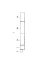
次に、本発明に係るキャリヤ連結装置の一実施形態について図面を参照しながら以下に説明する。図1は、キャリヤの編成による搬送車両の編成の一例を示した概念図である。この搬送車両1は、例えば図示するように、一つの運転室2及びパワーユニット3を備え、それに複数のキャリヤ10a,10b,10c(まとめて「キャリヤ10」とする)が連結される。先頭のキャリヤ10aにはパワーユニット3を介して運転室2が設けられ、主動型キャリヤを構成するが、その後に連結されたキャリヤ10b,10cはキャリヤ単体では駆動手段をもたない従動型キャリヤである。
Next, an embodiment of a carrier connecting device according to the present invention will be described below with reference to the drawings. FIG. 1 is a conceptual diagram showing an example of knitting of a transport vehicle by carrier knitting. The
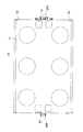
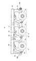
次に、図2及び図3はキャリヤを示した平面図と側面図である。キャリヤ10は、荷台11の下に走行装置12,13が複数設けられたものである。前後方向中央の走行装置12は、それぞれ左右2個ずつ計4個のタイヤ21を有し、タイヤ21を旋回させるサスペンションブラケット22のアームに対し、上下方向に揺動可能なスイングアーム23が設けられ、そのスイングアーム23が油圧シリンダ24で支持されたジャッキアップ機構が構成されている。また、走行装置12には、車軸を回転させる油圧モータ(走行モータ)や、サスペンションブラケットを旋回させる油圧シリンダ(操舵シリンダ)が設けられている。
Next, FIG.2 and FIG.3 is the top view and side view which showed the carrier. The
一方、前後方向両側の走行装置13も、それぞれ左右2個ずつ計4個のタイヤ21を有し、タイヤ21を旋回させるサスペンションブラケット22のアームに対し、上下方向に揺動可能なスイングアーム25が設けられ、そのスイングアーム25が油圧シリンダ24で支持されたジャッキアップ機構が構成されている。しかし、走行装置13は、走行装置12が走行モータを持った駆動輪であるのに対し、制動装置や操舵機構は有するものの走行モータを持たない従動輪である。
On the other hand, the
搬送車両1を構成する各キャリヤ10の走行及び操舵は、運転室2におけるハンドルもしくはジョイスティックやアクセルペダルの操作に従い不図示のコントローラから指令信号が送られ、各走行装置12,13の走行モータや操舵シリンダの制御が行われる。パワーユニット3は、例えばエンジンと油圧装置とを備えたものであり、エンジンを駆動させて油圧装置から油圧源を得てキャリヤ10の走行モータや操舵シリンダを駆動させる。また、油圧装置に接続された油圧ポンプを有し、走行装置12,13の油圧シリンダなどに作動油を供給できるよう構成されている。従って、編成後のキャリヤ10同士は、機械的な連結の他、走行装置12,13を制御させるため電気回路や油圧回路を構成するためケーブルや油圧配管による連結も必要になる。
For the traveling and steering of each
ところで、図2及び図3に示すキャリヤ10は、走行装置12,13を前後左右に6機を有する6軸キャリヤであるが、その他にも4軸や8軸などのサイズの異なるキャリヤも存在する。そうしたキャリヤが任意に選択され、互いに連結されて搬送車両を編成することとなる。例えば図1に示す搬送車両1は、6軸のキャリヤ10a,10bと4軸キャリヤ10cによって編成されたものである。
The
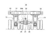
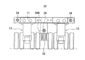
続いて、キャリヤ10同士を機械的に連結するキャリヤ連結装置(以下、単に「連結装置」とする)について図4及び図5を加えて説明する。図4及び図5は、キャリヤを前後方向の一方と反対の他方とから見た図である。
本実施形態の連結装置は、前述した第2従来例と同様に、車体左右方向に重ねた連結プレートの貫通孔に油圧シリンダを挿入する構成を利用している。従って、キャリヤ10には、図2に示すように、荷台11の前後方向の端部中央に複数の連結プレート31,32がそれぞれ突設されている。連結部30Aを構成する4枚の連結プレート31と、連結部30Bを構成する3枚の連結プレート32は、それぞれ車体左右方向に所定の間隔で配置され、同じ大きさの円形の貫通孔が車体左右方向の同じ位置に形成されている。
Subsequently, a carrier connecting device (hereinafter simply referred to as “connecting device”) for mechanically connecting the
As in the second conventional example described above, the coupling device of this embodiment uses a configuration in which a hydraulic cylinder is inserted into a through hole of a coupling plate that is overlapped in the left-right direction of the vehicle body. Therefore, as shown in FIG. 2, the
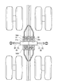
これらはキャリヤ10同士が車体前後方向に連結される際、一方のキャリヤ10の連結プレート31の各間に、他方のキャリヤ10の連結プレート32が入り込んで噛み合うようになっている。そして、重なった7枚の連結プレート31,32には、図9に示すように左右方向から一対の油圧シリンダ35が挿入され、中央に位置する連結プレート32で突き当たるようになっている。その中央に位置する連結プレート32は、他の連結プレート32よりも厚みがあり、連結プレート31側は、その中央位置の間隔が広くとられている。
When the
噛み合いにより車体左右方向へ重なった7枚の連結プレート31,32は、全ての貫通孔が揃っていなければ油圧シリンダ35の挿入ができなくなる。そのため、キャリヤ10の連結プレート31側端部には、位置決用の突起33が3箇所に形成され、反対の連結プレート32側端部には、突起33が入り込む凹部34が3箇所に形成されている。連結の際には、キャリヤ10同士が前後に突き当てられ、突起33と凹部34に嵌合することにより、7枚のプレート31,32の貫通孔が揃うようになっている。
The seven connecting
次に、連結プレート31と共に連結部30Aを構成する油圧シリンダ35について説明する。連結部30Aには、図4に示すように、噛み合った連結プレート31,32を分離させないための油圧シリンダ35が左右一対に設けられている。前述した第2従来例では一方向のみから挿入するため1本の油圧シリンダで構成していたが、本実施形態では左右2本の油圧シリンダ35で連結するように構成されている。そのため、従来の油圧シリンダは300mm程度のストロークを必要としていたが、本実施形態では、油圧シリンダ35のストロークは175mmとなり、約半分の長さに縮めたものが使用される。
Next, the
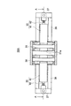
こうした一対の油圧シリンダ35は、連結プレート31,32が噛み合った場合に、車体左右方向の外側から挿入されるため、連結プレート31側に取り付けられている。ここで、図6は、図4と同じ方向から見た連結部30Aの一部断面図である。4枚の連結プレート31は、ベースフレーム38に対して一体に形成され、その両端に位置する連結プレート31に支持フレーム36が固定されている。
The pair of
油圧シリンダ35は、そうした支持フレーム36にそれぞれボールジョイントの継手37によって連結されている。特に、油圧シリンダ35は、ピストンロッド42が継手37を介して支持フレーム36に連結された固定側となり、シリンダ本体41が連結プレート31,32内を移動する可動側として取り付けられている。可動側のシリンダ本体41は、その先端にテーパ面が形成され、連結プレート31,32間に多少のずれが生じていてもスムーズに挿入できるようになっている。
The
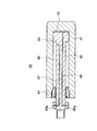
図7は、油圧シリンダ35を示した断面図である。筒状のシリンダ本体41は、一端側を開口した有底円筒体であり、その開口部側からピストン43を備えたピストンロッド42が挿入されている。シリンダ本体41の開口部には、ピストンロッド42を摺動可能に通した状態で内部を気密にするための栓部材44が、そのシリンダ本体41の雌ネジに対して形成した雄ネジによって螺設されている。
FIG. 7 is a cross-sectional view showing the
また、シリンダ本体41は、噛み合った連結プレート31,32による剪断力を受けるため十分な剛性が必要である。そこで、油圧シリンダ35は、シリンダ本体41が十分な肉厚を有し、シリンダ本体41の強度を落とさない構造となっている。すなわち、作動油を通す流路がピストンロッド42側に設けられている。ピストンロッド42は、シリンダ本体41の外側端部にポートブロック45a,45bが設けられ、中実の棒材に伸長側流路46や収縮側流路47が形成されている。そして、こうした油圧シリンダ35は、図6に示すように、ピストンロッド42が支持フレーム36に軸着され、シリンダ本体41の先端部分が予め連結プレート31の貫通孔31a内に挿入した状態で取り付けられる。
In addition, the
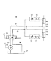
ところで、本実施形態では、油圧シリンダ35を2本にすることでストロークの短い短尺シリンダで連結装置を構成している。そのため、各油圧シリンダ35に給排する作動油の量を少なくし、また作動油を流すための油圧抵抗も小さくすることができるので、本実施形態では、ハンドポンプを利用した作業者の連結動作によってキャリヤ10同士の連結を可能にした構成となっている。ここで、図8は、油圧シリンダ35を作動させる連結装置の油圧回路を示した図である。なお、図8では、シリンダ本体41を介して作動油が給排されるよう単純に表現しているが、具体的には前述したようにピストンロッド42を介して行われる。
By the way, in this embodiment, the connection apparatus is comprised by the short cylinder with a short stroke by using the two
一対の油圧シリンダ35には、それぞれのヘッド側(図7に示す伸長側流路46)に配管51が分岐して接続され、ロッド側(図7に示す収縮側流路47)には配管52が分岐して接続されている。特に、分岐した配管52には、各油圧シリンダ35に対して可変の絞り弁53とストップ弁54とがそれぞれ設けられている。絞り弁53は、作動油の流量を調整することで油圧シリンダ35の伸縮速度を調整するようにしたものであり、ストップ弁54は、作動油の流れを止めて油圧シリンダ35の作動状態を保持する手動の遮断弁である。
A
配管51,52には、タンク57との間に手動切換弁55とハンドポンプ56とが接続されている。手動切換弁55は、4ポート弁であって、配管51,52を交互にハンドポンプ56とタンク57とに切り換えられるようにしたものであり、ハンドポンプ56は、レバーの操作によって油圧シリンダ35へ作動油を送り込むためのものである。そして、こうした油圧回路50を構成する各機器は、油圧シリンダ35と共に各キャリヤ10に搭載されている。
A manual switching valve 55 and a
そこで、次に本実施形態の連結装置を使用したキャリヤ10同士の連結について説明する。図9は、連結装置の連結状態を示した図であり、図6のA−A矢視による平面方向の一部断面図である。
先ず、キャリヤ10を編成した搬送車両を構成するには、主動型や従動型にかかわらず車体前後方向に配置したキャリヤ10同士を前後に移動させ、連結プレート31,32を噛み合わせればよい。トレーラによって運ばれたキャリヤ10は、現場ではクレーンによって配置される。その際、本実施形態の連結装置を備えたキャリヤ10は、従動型同士でもクレーンによる簡単な移動で連結が可能になる。すなわち、連結プレート31,32が図9に示すように噛み合わせた後、各キャリヤ10に搭載された図8に示す流体機器を操作することで連結を完了することができる。
Then, the connection of the
First, in order to configure a transport vehicle in which the
具体的には、キャリヤ10に搭載されたストップ弁54を開き、手動切換弁55の操作によってハンドポンプ56側の配管58と配管51とが接続され、タンク57側の配管59と配管52とが接続されるように切り換えられる。そして、ハンドポンプ56を操作してタンク57内の作動油が送り出される。タンク57内の作動油は、配管51を通り油圧シリンダ35のヘッド室48へと流れ込み、油圧シリンダ35を伸長作動させる。一方、油圧シリンダ35のロッド室49内の作動油は押し出され、ストップ弁54及び絞り弁53を通って配管52を流れてタンク57へ戻される。このとき、絞り弁53によって作動油の流量が抑えられるため、油圧シリンダ35が適切なスピードで伸長作動することになる。
Specifically, the
そして、これを図7に示す油圧シリンダ35で見てみると、ハンドポンプ56によって送り込まれた作動油は、ピストンロッド42のポートブロック45a側から伸長側流路46へと流れ込み、ヘッド室48へと供給されシリンダ本体41を加圧して図面右側へと移動させた伸長作動となる。一方、油圧シリンダ35の伸長作動によってロッド室49が縮小するため、内部の作動油が押し出されて収縮側流路47からポートブロック45b側へ流れ出る。
When this is viewed with the
そして、伸長作動した左右一対の油圧シリンダ35は、各シリンダ本体41が、図9に示すように貫通孔31a,32aによって構成された一つの孔に左右から挿入され、中央で突き当てられる。こうして連結プレート31,32の噛み合いが維持され、キャリヤ10同士の連結が行われる。左右のシリンダ本体41は、肉厚の連結プレート32に入り込んだ中央位置までしか伸びないが、このとき互いが僅かに押し合うようにして突き当てられるように設定されている。その後、キャリヤ10の走行振動などによって油圧シリンダ35が作動して抜けてしまわないように、ストップ弁54を閉状態にして作動油の流れを遮断して連結状態を維持するようにしている。
Then, in the pair of left and right
次に、連結を解除する場合は、ストップ弁54を開状態にし、手動切換弁55の操作によってハンドポンプ56側の配管58と配管52とが接続され、タンク57側の配管59と配管51とが接続するように切り換えられる。そして、ハンドポンプ56を操作してタンク57内の作動油が送り出され、配管52からロッド室49へと流れ込み、その油圧シリンダ35が収縮作動する。一方、油圧シリンダ35のヘッド室48内の作動油は押し出され、配管51を通ってタンク57へと戻される。
Next, when releasing the connection, the
そして、これを図7に示す油圧シリンダ35で見てみると、ハンドポンプ56によって送り込まれた作動油は、ピストンロッド42のポートブロック45b側から収縮側流路47へと流れ込み、ロッド室49へ供給され、栓部材44側を加圧して図面左側へとシリンダ本体41を移動させた収縮作動となる。一方、油圧シリンダ35の収縮作動によってヘッド室48が縮小するため、内部の作動油が押し出されて伸長側流路46から流れ出る。そして、図9に示す連結状態の油圧シリンダ35は、各シリンダ本体41が図6に示すように左右両側へ移動して貫通孔31a,32aから抜ける。こうして連結プレート31,32の噛み合い解除可能な状態になり、キャリヤ10同士を車体前後方向へ離すことにより分離させることができる。
When this is viewed in the
こうした本実施形態の連結装置によれば、油圧シリンダ35を左右一対の構成にし、ハンドポンプ56によってキャリヤ10同士を連結させるようにしたので、主動型キャリヤから油圧を得ることなく連結作業が行えるようになった。そのため、従動型キャリヤ同士であっても連結することができ、現場におけるキャリヤ10同士の連結について作業性が向上した。特に、パワーユニット3の油圧を使用せず、すなわちキャリヤ10同士の油圧配管などの接続を行わずに連結作業を行えるため、連結作業を単純にすることができ、しかもストップ弁54や手動切換弁55の切り換えや、ハンドポンプ56の操作といった簡単な作業で連結が行える。
According to the coupling device of this embodiment, the
本発明に係るキャリヤ連結装置について実施形態を説明したが、本発明はこれに限定されることなく、その趣旨を逸脱しない範囲で様々な変更が可能である。
前記実施形態では、キャリヤ連結装置を構成する連結プレート31,32を4枚と3枚の組み合わせにしたが、例えば5枚と4枚の組み合わせなど、数を変えたものであってもよい。
また、前記実施形態では、ストップ弁54を遮断弁として使用したが、これをニードル弁に置き換えても良い。
Although the embodiment of the carrier coupling device according to the present invention has been described, the present invention is not limited to this, and various modifications can be made without departing from the scope of the present invention.
In the above-described embodiment, the
Moreover, in the said embodiment, although the
1 搬送車両
3 パワーユニット
10 キャリヤ
12,13 走行装置
30A,30B 連結部
31,32 連結プレート
35 油圧シリンダ
36 支持フレーム
41 シリンダ本体
42 ピストンロッド
50 油圧回路
53 絞り弁
54 ストップ弁
55 手動切換弁
56 ハンドポンプ
57 タンク
DESCRIPTION OF
Claims (3)
前記一方のキャリヤは、前記複数配置された連結プレートの車体左右方向の両外側に設けられた一対の前記油圧シリンダと、その油圧シリンダに作動油を給排するためのタンク、手動切換弁およびハンドポンプを備えた油圧回路を有することを特徴とするキャリヤ連結装置。 There are multiple connecting plates arranged in the left-right direction of the vehicle body at the abutting end of one carrier arranged in the front-rear direction and the other carrier, and the connecting plates are alternately meshed in the left-right direction of the vehicle body and formed on each connecting plate A carrier connecting device for connecting through a hydraulic cylinder to a hole formed by stacking through-holes,
The one carrier includes a pair of the hydraulic cylinders provided on both outer sides of the plurality of connecting plates in the lateral direction of the vehicle body, a tank for supplying and discharging hydraulic oil to the hydraulic cylinders, a manual switching valve, and a hand. A carrier coupling device comprising a hydraulic circuit having a pump.
前記油圧回路には、絞り弁と遮断弁とが前記各油圧シリンダに対する流路にそれぞれ直列に設けられたものであることを特徴とするキャリヤ連結装置。 The carrier coupling device according to claim 1.
The carrier connection device according to claim 1, wherein a throttle valve and a shut-off valve are provided in series in a flow path for each hydraulic cylinder in the hydraulic circuit.
前記油圧シリンダは、シリンダ本体内のヘッド室とロッド室に対する作動油の給排のための流路がピストンロッドに形成され、前記連結プレートの貫通孔を重ねた孔へはシリンダ本体を挿入させるようにしたものであることを特徴とするキャリヤ連結装置。 The carrier connecting device according to claim 1 or 2,
In the hydraulic cylinder, a flow path for supplying and discharging hydraulic oil to and from the head chamber and the rod chamber in the cylinder body is formed in the piston rod, and the cylinder body is inserted into a hole in which the through holes of the connection plate are overlapped. A carrier connecting device characterized in that the carrier connecting device is made.
Priority Applications (1)
| Application Number | Priority Date | Filing Date | Title |
|---|---|---|---|
| JP2009291559A JP5554557B2 (en) | 2009-12-23 | 2009-12-23 | Carrier coupling device |
Applications Claiming Priority (1)
| Application Number | Priority Date | Filing Date | Title |
|---|---|---|---|
| JP2009291559A JP5554557B2 (en) | 2009-12-23 | 2009-12-23 | Carrier coupling device |
Publications (2)
| Publication Number | Publication Date |
|---|---|
| JP2011131663A true JP2011131663A (en) | 2011-07-07 |
| JP5554557B2 JP5554557B2 (en) | 2014-07-23 |
Family
ID=44344889
Family Applications (1)
| Application Number | Title | Priority Date | Filing Date |
|---|---|---|---|
| JP2009291559A Active JP5554557B2 (en) | 2009-12-23 | 2009-12-23 | Carrier coupling device |
Country Status (1)
| Country | Link |
|---|---|
| JP (1) | JP5554557B2 (en) |
Citations (7)
| Publication number | Priority date | Publication date | Assignee | Title |
|---|---|---|---|---|
| JPS58102383U (en) * | 1981-12-29 | 1983-07-12 | 有限会社河島農具製作所 | multi-wheel drive vehicle |
| JPS6437707U (en) * | 1987-09-02 | 1989-03-07 | ||
| JPH0458605U (en) * | 1990-09-27 | 1992-05-20 | ||
| JPH08290710A (en) * | 1995-04-21 | 1996-11-05 | Nissan Motor Co Ltd | Automated guided vehicle |
| US5584407A (en) * | 1995-06-28 | 1996-12-17 | Westinghouse Air Brake Company | Interlocking slackless drawbar assembly for railway freight car and an interlocking mechanism therefor |
| JPH09142307A (en) * | 1995-11-17 | 1997-06-03 | Mitsubishi Motors Corp | Transport trolley |
| JP2001328572A (en) * | 2000-05-22 | 2001-11-27 | Tcm Corp | Industrial vehicle |
-
2009
- 2009-12-23 JP JP2009291559A patent/JP5554557B2/en active Active
Patent Citations (7)
| Publication number | Priority date | Publication date | Assignee | Title |
|---|---|---|---|---|
| JPS58102383U (en) * | 1981-12-29 | 1983-07-12 | 有限会社河島農具製作所 | multi-wheel drive vehicle |
| JPS6437707U (en) * | 1987-09-02 | 1989-03-07 | ||
| JPH0458605U (en) * | 1990-09-27 | 1992-05-20 | ||
| JPH08290710A (en) * | 1995-04-21 | 1996-11-05 | Nissan Motor Co Ltd | Automated guided vehicle |
| US5584407A (en) * | 1995-06-28 | 1996-12-17 | Westinghouse Air Brake Company | Interlocking slackless drawbar assembly for railway freight car and an interlocking mechanism therefor |
| JPH09142307A (en) * | 1995-11-17 | 1997-06-03 | Mitsubishi Motors Corp | Transport trolley |
| JP2001328572A (en) * | 2000-05-22 | 2001-11-27 | Tcm Corp | Industrial vehicle |
Non-Patent Citations (1)
| Title |
|---|
| JPN7014001571; Goldhofer Aktiengesellschaft: Modulare Schwerlastfahrzeuge , 200808, P11,13,27,32,33, Goldhofer Aktiengesellschaft * |
Also Published As
| Publication number | Publication date |
|---|---|
| JP5554557B2 (en) | 2014-07-23 |
Similar Documents
| Publication | Publication Date | Title |
|---|---|---|
| US8776939B2 (en) | Working vehicle | |
| US8469137B2 (en) | Working vehicle | |
| JP2001193010A (en) | Hand guide roller | |
| CN110709562B (en) | work machinery | |
| JP5554557B2 (en) | Carrier coupling device | |
| TW201441086A (en) | Work vehicle | |
| US3134455A (en) | Universal truck with steering and driving wheels | |
| AU2013347045B2 (en) | Steering system for an industrial truck | |
| JP2012512087A (en) | Variable gauge chassis | |
| CN102259589B (en) | The drive mechanism of working rig | |
| JP2016159725A (en) | Work vehicle | |
| KR100808914B1 (en) | External welding machine of steel pipe | |
| US9180850B2 (en) | Working vehicle | |
| JP2005297710A (en) | Power transmission device for work vehicle | |
| TWI640240B (en) | Work vehicle | |
| JP6344854B2 (en) | Rolling machine | |
| JP2014166801A (en) | Work vehicle | |
| EP3686355B1 (en) | Hydraulic excavator | |
| US20200048859A1 (en) | Hydraulic system for working machine | |
| CN204775502U (en) | Work vehicle | |
| CN101767604B (en) | Steering control device for engineering machinery | |
| JP4496025B2 (en) | Hydraulic hose retainer for articulated vehicles | |
| US11174623B2 (en) | Flow rate control valve | |
| KR101382993B1 (en) | Power steering system for vehicle | |
| JP4471916B2 (en) | Wheeled work machine |
Legal Events
| Date | Code | Title | Description |
|---|---|---|---|
| A621 | Written request for application examination |
Free format text: JAPANESE INTERMEDIATE CODE: A621 Effective date: 20121126 |
|
| A977 | Report on retrieval |
Free format text: JAPANESE INTERMEDIATE CODE: A971007 Effective date: 20131105 |
|
| A131 | Notification of reasons for refusal |
Free format text: JAPANESE INTERMEDIATE CODE: A131 Effective date: 20131203 |
|
| A521 | Request for written amendment filed |
Free format text: JAPANESE INTERMEDIATE CODE: A523 Effective date: 20140127 |
|
| TRDD | Decision of grant or rejection written | ||
| A01 | Written decision to grant a patent or to grant a registration (utility model) |
Free format text: JAPANESE INTERMEDIATE CODE: A01 Effective date: 20140527 |
|
| A61 | First payment of annual fees (during grant procedure) |
Free format text: JAPANESE INTERMEDIATE CODE: A61 Effective date: 20140529 |
|
| R150 | Certificate of patent or registration of utility model |
Ref document number: 5554557 Country of ref document: JP Free format text: JAPANESE INTERMEDIATE CODE: R150 |
|
| R250 | Receipt of annual fees |
Free format text: JAPANESE INTERMEDIATE CODE: R250 |
|
| R250 | Receipt of annual fees |
Free format text: JAPANESE INTERMEDIATE CODE: R250 |
|
| R250 | Receipt of annual fees |
Free format text: JAPANESE INTERMEDIATE CODE: R250 |
|
| R250 | Receipt of annual fees |
Free format text: JAPANESE INTERMEDIATE CODE: R250 |
|
| R250 | Receipt of annual fees |
Free format text: JAPANESE INTERMEDIATE CODE: R250 |
|
| R250 | Receipt of annual fees |
Free format text: JAPANESE INTERMEDIATE CODE: R250 |
|
| R250 | Receipt of annual fees |
Free format text: JAPANESE INTERMEDIATE CODE: R250 |
|
| R250 | Receipt of annual fees |
Free format text: JAPANESE INTERMEDIATE CODE: R250 |
|
| R250 | Receipt of annual fees |
Free format text: JAPANESE INTERMEDIATE CODE: R250 |