JP2011129653A - Measurement method and exposure apparatus - Google Patents
Measurement method and exposure apparatus Download PDFInfo
- Publication number
- JP2011129653A JP2011129653A JP2009285769A JP2009285769A JP2011129653A JP 2011129653 A JP2011129653 A JP 2011129653A JP 2009285769 A JP2009285769 A JP 2009285769A JP 2009285769 A JP2009285769 A JP 2009285769A JP 2011129653 A JP2011129653 A JP 2011129653A
- Authority
- JP
- Japan
- Prior art keywords
- optical system
- projection optical
- light
- measurement
- pattern
- Prior art date
- Legal status (The legal status is an assumption and is not a legal conclusion. Google has not performed a legal analysis and makes no representation as to the accuracy of the status listed.)
- Pending
Links
Images


Abstract
Description
本発明は、計測方法及び露光装置に関する。 The present invention relates to a measurement method and an exposure apparatus.
フォトリソグラフィー技術を用いて半導体素子を製造する際に、マスク(レチクル)に描画された回路パターンを投影光学系によってウエハ等に投影して回路パターンを転写する投影露光装置が使用されている。 2. Description of the Related Art When a semiconductor element is manufactured using a photolithography technique, a projection exposure apparatus that projects a circuit pattern drawn on a mask (reticle) onto a wafer or the like by a projection optical system and transfers the circuit pattern is used.
リソグラフィー工程ではウエハ上に回路パターンを重ね合わせて形成する際、既にウエハ上に形成されたパターンと、その上に描写されるパターンとの重ね合わせ精度が重要である。重ね合わせ精度を向上させる対策の1つとして有効光源分布を調整する技術が注目されている(特許文献1、2参照)。有効光源分布とは、ウエハ面に入射する露光光束の角度分布を意味し、投影光学系の瞳面における光強度分布でもある。 In the lithography process, when a circuit pattern is superimposed on a wafer, the overlay accuracy between the pattern already formed on the wafer and the pattern drawn thereon is important. A technique for adjusting the effective light source distribution has attracted attention as one of the measures for improving the overlay accuracy (see Patent Documents 1 and 2). The effective light source distribution means the angular distribution of the exposure light beam incident on the wafer surface, and is also the light intensity distribution on the pupil plane of the projection optical system.
従来は、有効光源分布の調整手段を制御しながら、所定の計測マークが形成された計測用マスクを用いてウエハの露光及び現像をし、ウエハ上に形成されるレジスト像の形状(位置、大きさ等)を計測していた。そして、計測結果を用いて、重ね合わせ精度に影響する、角度特性等の結像特性を算出するという方法がとられていた。このため、露光、現像及び計測の手間がかかる為に時間がかかっていた。また、この代替手段として、投影光学系の像面おける光強度分布(空中像)を観察する事により、重ね合わせ精度に影響する結像特性を測定する方法がある(特許文献3参照)。 Conventionally, while controlling the effective light source distribution adjusting means, the wafer is exposed and developed using a measurement mask on which predetermined measurement marks are formed, and the shape (position and size) of the resist image formed on the wafer is measured. Etc.). A method of calculating imaging characteristics such as angle characteristics that affect the overlay accuracy using the measurement result has been used. For this reason, it takes a lot of time for exposure, development and measurement. As an alternative, there is a method of measuring imaging characteristics that affect the overlay accuracy by observing the light intensity distribution (aerial image) on the image plane of the projection optical system (see Patent Document 3).
しかし、特許文献3に記載の方法では、投影光学系のNAと、計測用マスクのパターンの線幅との関係の記載がなく、投影光学系のNAが大きい場合など、高精度な測定を行うことができない。
However, in the method described in
そこで、本発明は、投影光学系の結像特性、特に露光光の角度特性を高精度に測定することを目的とする。 Accordingly, an object of the present invention is to measure with high accuracy the imaging characteristics of a projection optical system, particularly the angular characteristics of exposure light.
本発明の一側面としての計測方法は、光源からの光を用いてマスクを照明する照明光学系と、前記マスクのパターンを基板に投影する投影光学系とを有する露光装置を用いて、前記基板を露光する露光光の角度分布を計測する計測方法であって、前記光源の波長をλ、前記投影光学系の射出側開口数をNA、前記投影光学系の投影倍率をβとして、前記投影光学系の物体面にλ×10/(NA×β)以上の線幅の特定パターンを配置するステップと、前記特定パターンを照明し、前記投影光学系の光軸方向における複数の位置における前記特定パターンの像をセンサを用いて計測するステップと、該計測結果を用いて、露光光の角度特性を算出するステップとを有することを特徴とする。 According to another aspect of the present invention, there is provided a measurement method using an exposure apparatus having an illumination optical system that illuminates a mask using light from a light source and a projection optical system that projects a pattern of the mask onto the substrate. Is a measurement method for measuring the angular distribution of exposure light for exposing the projection optical system, wherein the wavelength of the light source is λ, the exit numerical aperture of the projection optical system is NA, and the projection magnification of the projection optical system is β. Arranging a specific pattern having a line width of λ × 10 / (NA × β) or more on the object plane of the system, illuminating the specific pattern, and the specific pattern at a plurality of positions in the optical axis direction of the projection optical system A step of measuring the image using a sensor, and a step of calculating an angle characteristic of the exposure light using the measurement result.
本発明の一側面としての露光装置は、光源からの光を用いてマスクを照明する照明光学系と、前記マスクのパターンを基板に投影する投影光学系と、前記マスクのパターンの像を計測するセンサと、前記センサからの計測データを用いて露光光の角度特性を算出する制御部とを有する露光装置において、前記マスク又は前記マスクを保持するマスクステージに、互いに線幅が異なる複数の計測用パターンが形成され、前記光源の波長をλ、前記投影光学系の射出側開口数をNA、前記投影光学系の投影倍率をβとして、前記制御部は、前記計測用パターンのうちλ×10/(NA×β)以上の線幅の特定パターンが照明されるように前記マスクステージの駆動を制御し、前記投影光学系の光軸方向における複数の位置における前記特定パターンの像を前記センサが計測して得られた計測結果を用いて、前記基板を露光する露光光の角度特性を算出することを特徴とする。 An exposure apparatus according to one aspect of the present invention measures an illumination optical system that illuminates a mask using light from a light source, a projection optical system that projects the mask pattern onto a substrate, and an image of the mask pattern. In an exposure apparatus having a sensor and a control unit that calculates angle characteristics of exposure light using measurement data from the sensor, the mask or a mask stage that holds the mask has a plurality of measurement widths different from each other. A pattern is formed, where the wavelength of the light source is λ, the exit numerical aperture of the projection optical system is NA, and the projection magnification of the projection optical system is β, the control unit is λ × 10 / of the measurement pattern. The driving of the mask stage is controlled so that a specific pattern having a line width of (NA × β) or more is illuminated, and the specific pattern at a plurality of positions in the optical axis direction of the projection optical system is controlled. The using the measurement result obtained by the sensor is measured, and calculates the angular characteristics of the exposure light for exposing the substrate.
本発明によれば、投影光学系の結像特性、特に露光光の角度特性を高精度に測定することができる。 According to the present invention, it is possible to measure the imaging characteristics of the projection optical system, particularly the angular characteristics of exposure light, with high accuracy.
(実施例1)
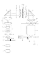
図1を用いて本発明の第1の実施例を説明する。図1は本実施例における露光装置の概略図である。
Example 1
A first embodiment of the present invention will be described with reference to FIG. FIG. 1 is a schematic view of an exposure apparatus in this embodiment.
光源1は例えば、波長が約193nmのArFエキシマレーザーや約248nmのKrFエキシマレーザーである。引き回し光学系2は光源1からの光束を回折光学素子3に導く。
The light source 1 is, for example, an ArF excimer laser having a wavelength of about 193 nm or a KrF excimer laser having a wavelength of about 248 nm. The routing optical system 2 guides the light beam from the light source 1 to the diffractive
回折光学素子3は複数のスロットを有するターレットに搭載されており、アクチュエーター4によって、任意の回折光学素子を光軸上に移動することが可能である。回折光学素子3の射出光は、コンデンサーレンズ5によって集光され、回折パターン面6に回折パターンを形成する。回折パターンは、アクチュエーター4により光軸上に位置する回折光学素子を交換することにより、変更することができる。回折パターン面6に形成された回折パターンは、プリズム7及びズームレンズ8によって光束断面形状(輪帯率や外径など)が調整された後、ミラー9に入射する。
The diffractive
ミラー9によって反射した光束は光強度分布形成手段10に入射する。本実施例では光強度分布形成手段10はレンズアレイである。プリズム7はズーミングすることが可能であり、プリズム7aと7bの距離が十分に小さい場合、プリズム7aと7bは一体化した一枚の平行平板ガラスとみなすことができる。このとき、回折パターン面6に形成された回折パターンは、ほぼ相似形状を保ちながらズームレンズ8の拡大縮小により光束径(σ値)が調整され、光強度分布形成手段10の入射面に結像される。また、プリズム7aと7bの位置を離すことによって、回折パターン面6に形成された回折パターンが調整される。
The light beam reflected by the mirror 9 enters the light intensity
光強度分布形成手段10の射出光束はコンデンサーレンズ11で集光されて、遮光部材13が配置されている面(被照射面と共役な面)を所望の光強度分布で照明する。遮光部材13は、被照射面に配置されるマスク17の照明範囲を規定し、マスク17を保持するマスクステージ21およびウエハを保持したウエハステージ19の走査に同期して動作が制御される。
The emitted light beam of the light intensity
遮光部材12は、遮光部材13が配置されている面からデフォーカスされた位置に配置されており、遮光部材13のある面に台形状の光強度分布(縦軸:光強度、横軸:光束断面における位置)を形成する。光強度分布を台形状にすることで、ウエハを露光する際に、パルスの不連続性に起因する走査方向の積算露光量のムラを避ける事ができる。また、遮光部材12の、ステージの走査方向に対応する方向の開口幅を変更することにより、X方向(走査方向と垂直な方向)の像高毎の、走査方向に積算した積算露光量のムラを避けることができる。
The
遮光部材13を通過した光は、レンズ14、ミラー15、レンズ16を経て、マスク17を照明する。マスク17のパターンの像は投影光学系18によって、ウエハステージ19に保持されるウエハに露光される。
The light that has passed through the
センサ20は光量を検知することが出来るCCDセンサやフォトダイオードセンサである。センサ20は、ウエハステージ19上に配置され、投影光学系18の像面、又は、像面からデフォーカスした位置に位置決めされて、投影光学系からの光を受光し、露光光の光強度(照度)を測定することができる。
The
次に、露光光の角度特性を計測するための計測用パターンを説明する。計測用パターンは、計測用マスクまたはマスクステージ21に形成される。 Next, a measurement pattern for measuring the angle characteristic of exposure light will be described. The measurement pattern is formed on a measurement mask or mask stage 21.
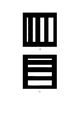
図2に計測用マスクに形成される計測用パターンの一例を示す。図2において、黒は遮光部を、白は光透過部(開口部)を表す。ただし、逆でもよい。図2(a)に示すパターンは、ウエハを照射する照射光のX方向(走査方向と垂直な方向)の角度分布特性を計測するためのパターンであり、それぞれ線幅が異なる複数の光透過部を含む。なお、計測用パターンという用語は、複数の光透過部から成るものに限らず、1つの光透過部のみをも意味するものとして用いる。 FIG. 2 shows an example of a measurement pattern formed on the measurement mask. In FIG. 2, black represents a light shielding portion and white represents a light transmission portion (opening portion). However, the reverse is also possible. The pattern shown in FIG. 2A is a pattern for measuring the angular distribution characteristics in the X direction (direction perpendicular to the scanning direction) of the irradiation light that irradiates the wafer, and a plurality of light transmission portions each having a different line width. including. Note that the term “measurement pattern” is not limited to a plurality of light transmission parts, and is used to mean only one light transmission part.
本実施例では、後述するように、複数の光透過部の中から、λ×10/(NA×β)以上となる線幅の光透過部(パターン)が選択され、照明される。なお、光源1の波長をλ、投影光学系18の射出側開口数をNA、投影光学系18の投影倍率をβとする。そのため、投影光学系18のNAが変更されると、投影光学系18のNAに応じて、選択されるパターンが変更される。
In this embodiment, as will be described later, a light transmissive portion (pattern) having a line width of λ × 10 / (NA × β) or more is selected from a plurality of light transmissive portions and illuminated. It is assumed that the wavelength of the light source 1 is λ, the exit numerical aperture of the projection
図2(b)に示すパターンは、ウエハを照射する照射光のY方向(走査方向)の角度分布特性を計測するためのパターンであり、それぞれ線幅が異なる複数の光透過部(開口部)を有する。図2に示す計測用パターンと同様に、投影光学系のNAに応じて、λ×10/(NA×β)以上となる線幅の光透過部が選択される。 The pattern shown in FIG. 2B is a pattern for measuring the angular distribution characteristics in the Y direction (scanning direction) of the irradiation light that irradiates the wafer, and a plurality of light transmission parts (openings) each having a different line width. Have Similar to the measurement pattern shown in FIG. 2, a light transmission portion having a line width of λ × 10 / (NA × β) or more is selected according to the NA of the projection optical system.
図3(a)に計測用パターンの別の例を示す。図3(a)に示すパターンは、ウエハを照射する照射光のX方向(走査方向と垂直な方向)の角度分布特性を計測するためのパターンである。図3(a)に示すパターンは、同一線幅の複数の光透過部(開口部)を1つの群(パターン)として、群毎に線幅の異なる複数の群を含む。この場合も、投影光学系のNAに応じて、λ×10/(NA×β)以上となる線幅のパターンが選択される。 FIG. 3A shows another example of the measurement pattern. The pattern shown in FIG. 3A is a pattern for measuring the angular distribution characteristics in the X direction (direction perpendicular to the scanning direction) of the irradiation light that irradiates the wafer. The pattern shown in FIG. 3A includes a plurality of groups having different line widths for each group, with a plurality of light transmission portions (openings) having the same line width as one group (pattern). Also in this case, a pattern having a line width of λ × 10 / (NA × β) or more is selected according to the NA of the projection optical system.
図2に示すパターンの代わりに、図3(a)に示す計測用パターンを用いると、センサで検出される総光量が向上し、ノイズの影響を低減できる。また、光透過部の製造による線幅誤差の影響も低減できる。 If the measurement pattern shown in FIG. 3A is used instead of the pattern shown in FIG. 2, the total light amount detected by the sensor is improved, and the influence of noise can be reduced. Moreover, the influence of the line width error due to the manufacture of the light transmission part can also be reduced.
なお、計測用パターンの光透過部は、図2、3(a)に示した長方形に限らず、正方形でもよい。正方形の場合は、1つのマスク(マスクステージ)に形成された正方形のパターンのみでX方向の角度分布特性とY方向の角度分布特性を取得することができる。 The light transmission part of the measurement pattern is not limited to the rectangle shown in FIGS. 2 and 3A, but may be a square. In the case of a square, the angular distribution characteristic in the X direction and the angular distribution characteristic in the Y direction can be acquired with only a square pattern formed on one mask (mask stage).
マスクに配置するスペースの大きさ(光透過部同士の間隔)は、光透過部に相当する空中像同士が重なりあわない程度でなければならず、最低でも、(NA/β×測定位置を表す像面からのデフォーカス距離)以上でなければならない。なお、デフォーカス距離は、投影光学系の光軸方向における、像面からの距離を表す。 The size of the space arranged on the mask (interval between the light transmitting portions) must be such that aerial images corresponding to the light transmitting portions do not overlap each other, and at least represents (NA / β × measurement position). Defocus distance from the image plane). The defocus distance represents a distance from the image plane in the optical axis direction of the projection optical system.
露光光の角度特性の測定を行う場合は、被照射面(投影光学系18の物体面)に計測用パターンを配置して、光源1からの光を用いて、照明光学系2〜16が計測用パターンを照明する。計測用パターンの像が投影光学系18によって像面に投影され、像面に光強度分布(空中像)が形成される。その際、空中像は、像面または像面近傍の複数の位置(投影光学系18の光軸方向の複数の位置)でセンサ20を用いて計測される。そして、計測結果を用いて露光光の角度特性を算出する。
When measuring the angular characteristics of the exposure light, the illumination optical systems 2 to 16 use the light from the light source 1 by placing a measurement pattern on the irradiated surface (the object surface of the projection optical system 18). Illuminate the pattern. An image of the measurement pattern is projected onto the image plane by the projection
なお、センサ20がCCDセンサである場合、レーザー光源からのパルス光を複数回発光して、その複数の光強度分布の平均値を算出することにより、計測精度を向上させることができる。センサ20がフォトダイオードの場合、像面上にスリットを置きスキャンすることにより波形を取得する事ができる。但し、スキャン時にステージの振動やステージの動作誤差により、測定値に誤差が乗ってしまうため、複数回スキャンして得られた測定結果を平均した値を用いることが望ましい。
When the
図3(a)に示す計測用パターンを用い、センサ20としてフォトダイオードを用いる場合に、像面上に配置されるスリットの例を図3(b)に示す。図3(b)に示す部材には、図3(a)に示す計測用パターンの位置に対応してスリット(白色部)が形成されている。スリットの幅は、小さいほど空中像を分解能よく測定することができるが、小さすぎるとフォトダイオードに入射する光量が小さくなる為に、センサのノイズによる誤差を受けてしまう。
FIG. 3B shows an example of slits arranged on the image plane when the measurement pattern shown in FIG. 3A is used and a photodiode is used as the
センサ20で取得される光強度分布の例を図4に示す。光強度分布は、計測用パターンの線幅、露光光の角度分布、及び、センサ20の測定位置(デフォーカス距離)に応じて異なる。図4は、デフォーカス距離だけを変更した場合の光強度分布の変化を表す。ベストフォーカス位置では、XY平面上位置5μmで急峻な曲線となっているが、デフォーカス距離が大きくなるにしたがって、その曲線がなだらかになっている。
An example of the light intensity distribution acquired by the
また、露光光の角度分布が変化すると、デフォーカス位置で、光強度分布全体のXY平面内位置がずれる(シフトする)。そのため、位置ずれ量及びデフォーカス距離を用いて、露光光の角度分布を算出することができる。 Further, when the angular distribution of the exposure light changes, the position in the XY plane of the entire light intensity distribution shifts (shifts) at the defocus position. Therefore, the angular distribution of the exposure light can be calculated using the positional deviation amount and the defocus distance.
図5に、あるデフォーカス距離において測定された光強度分布を示す。まず、光強度分布の特徴を表し、センサのノイズの影響を低減できる指定範囲(例えば、図5の太線四角枠で囲まれた範囲)、光強度が第1の指定値以上及び第2の指定値以下の範囲において、光強度分布の重心位置を求める。その重心位置をXY平面内における位置ずれ量とする。次に、デフォーカス距離を変更して、同様に光強度分布を測定し、重心位置を求める。そして、位置ずれ量の差分を、デフォーカス距離の差分で割ることにより、角度特性Tを算出する。式で表すと、T=(位置ずれ量1−位置ずれ量2)/(デフォーカス距離1―デフォーカス距離2)となる。なお、位置ずれ量は、重心位置に限らず、それ以外の指標も用いることができる。 FIG. 5 shows the light intensity distribution measured at a certain defocus distance. First, a specified range that represents the characteristics of the light intensity distribution and can reduce the influence of sensor noise (for example, a range surrounded by a thick square frame in FIG. 5), the light intensity is equal to or higher than the first specified value, and the second specified value. The barycentric position of the light intensity distribution is obtained within the range below the value. The position of the center of gravity is defined as a positional deviation amount in the XY plane. Next, the defocus distance is changed, the light intensity distribution is similarly measured, and the center of gravity position is obtained. Then, the angle characteristic T is calculated by dividing the difference in the amount of displacement by the difference in the defocus distance. Expressed by the equation, T = (position shift amount 1−position shift amount 2) / (defocus distance 1−defocus distance 2). Note that the positional deviation amount is not limited to the position of the center of gravity, and other indices can be used.
ここで、位置ずれ量の計測誤差としてステージの振動、センサの測定誤差、その他の装置の振動等が考えられる。位置ずれ量の計測誤差を低減する為には、センサのデフォーカス距離を大きく取る事が必要であり、そのためにはセンサをデフォーカスした位置での空中像が測定できる線幅の計測用パターンが必要である。 Here, as the measurement error of the positional deviation amount, stage vibration, sensor measurement error, vibration of other devices, and the like are conceivable. In order to reduce the measurement error of the positional deviation amount, it is necessary to increase the sensor defocus distance. To that end, a line width measurement pattern that can measure the aerial image at the position where the sensor is defocused is required. is necessary.
また、λ×10/(NA×β)以下の線幅の場合、測定に用いるデフォーカス距離が小さくなり、投影光学系の収差の影響による像の位置ずれ量が大きいために精度良く角度特性の計測をすることができない。 Also, in the case of a line width of λ × 10 / (NA × β) or less, the defocus distance used for the measurement is small, and the amount of positional deviation of the image due to the influence of the aberration of the projection optical system is large. I can't measure.
さらに、投影光学系のNAが大きい程、デフォーカス距離に対して空中像の形状変化が大きいので、より大きな線幅の計測パターンを使用した方が良い。 Furthermore, the larger the NA of the projection optical system, the larger the change in the shape of the aerial image with respect to the defocus distance, so it is better to use a measurement pattern with a larger line width.
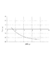
図6に投影光学系のNA(ウエハの照射光のNA)と空中像の形状変化を示す。図6(a)はλ=193nm、NA=0.3、デフォーカス距離を0〜7μmの条件で、マスク17に形成された線幅10μmの光透過部(開口部)を照明した時に、像面のセンサ20で検出される信号波形である。図6(b)は、NA以外が図6(a)に示す条件と同じで、NAを0.85とした場合の信号波形である。図6より、NAが大きいほどデフォーカス距離の変化に対して波形の変化が大きいことが分かる。
FIG. 6 shows the NA of the projection optical system (NA of the irradiation light of the wafer) and the shape change of the aerial image. FIG. 6A shows an image when a light transmitting portion (opening) having a line width of 10 μm formed on the
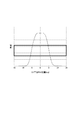
図7は、光透過部の線幅と、算出されたTの関係を示すグラフである。図7のデータを得るための測定では、照明光学装置の照射角度分布に不均一性をもたせて角度特性Tの値を設定し、光透過部の線幅(μm)を変化させた。測定条件は、λ=193nm、NA=0.93、β=1/4である。 FIG. 7 is a graph showing the relationship between the line width of the light transmitting portion and the calculated T. In the measurement for obtaining the data shown in FIG. 7, the value of the angle characteristic T is set with nonuniformity in the irradiation angle distribution of the illumination optical device, and the line width (μm) of the light transmission part is changed. The measurement conditions are λ = 193 nm, NA = 0.93, and β = 1/4.
図7から、角度特性Tは線幅が小さくなるほど、大きくなり、真の値からずれていることが分かる。なお、線幅が2μmのときのTの絶対値は、線幅がλ×10/(NA×β)=8.3μmのときのTの絶対値の1/4程度である。線幅がλ×10/(NA×β)以下である場合、ステージの振動、センサの測定誤差、装置の振動等の測定誤差を受けやすくなることにより、Tの測定誤差が大きくなってしまう。 FIG. 7 shows that the angle characteristic T increases as the line width decreases and deviates from the true value. The absolute value of T when the line width is 2 μm is about ¼ of the absolute value of T when the line width is λ × 10 / (NA × β) = 8.3 μm. When the line width is λ × 10 / (NA × β) or less, measurement errors such as stage vibrations, sensor measurement errors, and apparatus vibrations are easily received, thereby increasing T measurement errors.
したがって、λ×10/(NA×β)以上の線幅の光透過部を用いることにより、デフォーカス距離を大きくとることができ、角度特性を高精度に測定することができる。 Therefore, by using a light transmission portion having a line width of λ × 10 / (NA × β) or more, the defocus distance can be increased, and the angle characteristic can be measured with high accuracy.
そこで、本実施例では、計測用パターンとして、マスク又はマスクステージに形成された複数の光透過部(パターン)の中から、λ×10/(NA×β)以上となる線幅の光透過部(パターン)を選択して、照明する。 Therefore, in this embodiment, a light transmission portion having a line width of λ × 10 / (NA × β) or more from a plurality of light transmission portions (patterns) formed on a mask or a mask stage as a measurement pattern. Select (Pattern) and illuminate.
図7の測定フロー図を用いて、上述の計測用パターンを用いた、露光光の角度特性の測定方法を説明する。まず、制御部22は、光源の波長、投影光学系のNA及び倍率のデータを取得する(S101)。そして、計測用パターンのうち、λ×10/(NA×β)以上となる線幅のパターンを選択して、該選択されたパターン(特定パターン)が照明領域に入るように、制御部22がマスクステージ21の駆動(アクチュエータ)を制御する。また、制御部22はウエハステージ19の駆動を制御して、センサ20を露光領域に配置する(S102)。そして、λ×10/(NA×β)以上となる線幅のパターンを照明し(S103)、投影光学系18により投影された空中像を、あるデフォーカス距離においてセンサ20で測定する。次に、デフォーカス距離を変更して、同様の測定を行う。つまり、複数の位置(デフォーカス距離)で空中像の計測を行う(S104)。センサ20で得られた測定データ及びデフォーカス距離のデータは制御部22へ出力される。制御部22の演算処理部は、測定データを用いて光強度分布の位置ずれ量を算出し、さらにデフォーカス距離のデータを用いて、上記の式から角度特性Tを算出する(S105)。
A method for measuring the angle characteristic of exposure light using the above-described measurement pattern will be described with reference to the measurement flowchart of FIG. First, the control unit 22 acquires data on the wavelength of the light source, the NA of the projection optical system, and the magnification (S101). Then, the control unit 22 selects a pattern having a line width of λ × 10 / (NA × β) or more from the measurement patterns, and the selected pattern (specific pattern) enters the illumination area. The drive (actuator) of the mask stage 21 is controlled. Further, the control unit 22 controls the driving of the
なお、露光光の角度特性の測定結果は、露光装置の調整に用いることができる。例えば、角度特性の測定結果に基づき、所望の角度特性を目標値として、角度照明光学系及び投影光学系の少なくとも一方の光学素子の位置や角度を調整してもよい。また、露光装置(照明光学系、投影光学系など)を異なる複数の状態に設定して、照射光の角度特性を測定し、角度特性の値が小さい方の状態に、露光装置を調整する。調整の方法は、特許文献1又は2に記載の方法も用いることができる。 In addition, the measurement result of the angle characteristic of exposure light can be used for adjustment of an exposure apparatus. For example, based on the measurement result of the angle characteristic, the position and angle of at least one of the angle illumination optical system and the projection optical system may be adjusted using the desired angle characteristic as a target value. In addition, the exposure apparatus (illumination optical system, projection optical system, etc.) is set in a plurality of different states, the angular characteristics of the irradiated light are measured, and the exposure apparatus is adjusted to a state where the value of the angular characteristics is smaller. As a method of adjustment, the method described in Patent Document 1 or 2 can also be used.
以上より、本実施例によれば、露光光の角度特性を高精度に測定することができる。 As described above, according to the present embodiment, the angular characteristics of the exposure light can be measured with high accuracy.
(実施例2)
次に、前述の露光装置を利用したデバイス(半導体IC素子、液晶表示素子等)の製造方法を説明する。
(Example 2)
Next, a method for manufacturing a device (semiconductor IC element, liquid crystal display element, etc.) using the above-described exposure apparatus will be described.
まず、前述の露光装置を用いて、露光光の角度分布を測定する。そして、測定結果を用いて、露光装置の各光学系を制御することにより露光光の角度分布が調整される。そして、調整済みの露光装置を使用して、前述の露光装置を使用して、感光剤が塗布された基板(ウエハ、ガラス基板等)を露光する工程と、その基板(感光剤)を現像する工程と、他の周知の工程と、を経ることにより、デバイスが製造される。他の周知の工程には、エッチング、レジスト剥離、ダイシング、ボンディング、パッケージング等が含まれる。本デバイス製造方法によれば、従来よりも高品位のデバイスを製造することができる。 First, the angular distribution of exposure light is measured using the exposure apparatus described above. Then, the angular distribution of the exposure light is adjusted by controlling each optical system of the exposure apparatus using the measurement result. Then, using the adjusted exposure apparatus, the above-described exposure apparatus is used to expose a substrate (wafer, glass substrate, etc.) coated with a photosensitive agent, and the substrate (photosensitive agent) is developed. A device is manufactured through a process and other known processes. Other known processes include etching, resist stripping, dicing, bonding, packaging, and the like. According to this device manufacturing method, it is possible to manufacture a higher quality device than before.
17 マスク
18 投影光学系
19 ウエハステージ
20 センサ
21 マスクステージ
22 制御部
17
Claims (6)
前記光源の波長をλ、前記投影光学系の射出側開口数をNA、前記投影光学系の倍率をβとして、前記投影光学系の物体面にλ×10/(NA×β)以上の線幅の特定パターンを配置するステップと、
前記照明光学系を用いて前記特定パターンを照明し、前記投影光学系の光軸方向における複数の位置における前記特定パターンの像をセンサを用いて計測するステップと、
該計測結果を用いて、露光光の角度特性を算出するステップとを有することを特徴とする計測方法。 An angular distribution of exposure light that exposes the substrate is measured using an exposure apparatus that includes an illumination optical system that illuminates the mask using light from a light source and a projection optical system that projects the pattern of the mask onto the substrate. A measuring method,
A line width of λ × 10 / (NA × β) or more on the object plane of the projection optical system, where λ is the wavelength of the light source, NA is the exit numerical aperture of the projection optical system, and β is the magnification of the projection optical system. Placing a specific pattern of
Illuminating the specific pattern using the illumination optical system, and measuring images of the specific pattern at a plurality of positions in the optical axis direction of the projection optical system using a sensor;
And a step of calculating an angle characteristic of the exposure light using the measurement result.
前記マスクを保持するマスクステージ又は計測用マスクに、互いに線幅が異なる複数の計測用パターンが形成され、
前記露光装置は、
前記光源の波長をλ、前記投影光学系の射出側開口数をNA、前記投影光学系の倍率をβとして、前記計測用パターンのうちλ×10/(NA×β)以上の線幅の特定パターンを照明した状態で前記投影光学系の光軸方向における複数の位置における前記特定パターンの像を前記センサが計測して得られた計測結果、を用いて、前記基板を露光する露光光の角度特性を算出する制御部を有することを特徴とする露光装置。 In an exposure apparatus having an illumination optical system that illuminates a mask using light from a light source, a projection optical system that projects a pattern of the mask onto a substrate, and a sensor that receives light from the projection optical system,
A plurality of measurement patterns having different line widths are formed on the mask stage or measurement mask holding the mask,
The exposure apparatus includes:
Specifying a line width of λ × 10 / (NA × β) or more in the measurement pattern, where λ is the wavelength of the light source, NA is the exit numerical aperture of the projection optical system, and β is the magnification of the projection optical system The angle of the exposure light that exposes the substrate using the measurement results obtained by the sensor measuring the images of the specific pattern at a plurality of positions in the optical axis direction of the projection optical system with the pattern illuminated. An exposure apparatus having a control unit for calculating characteristics.
該露光された基板を現像するステップとを有することを特徴とするデバイス製造方法。 Exposing the substrate using the exposure apparatus according to claim 5;
And developing the exposed substrate. A device manufacturing method comprising:
Priority Applications (1)
| Application Number | Priority Date | Filing Date | Title |
|---|---|---|---|
| JP2009285769A JP2011129653A (en) | 2009-12-16 | 2009-12-16 | Measurement method and exposure apparatus |
Applications Claiming Priority (1)
| Application Number | Priority Date | Filing Date | Title |
|---|---|---|---|
| JP2009285769A JP2011129653A (en) | 2009-12-16 | 2009-12-16 | Measurement method and exposure apparatus |
Publications (1)
| Publication Number | Publication Date |
|---|---|
| JP2011129653A true JP2011129653A (en) | 2011-06-30 |
Family
ID=44291942
Family Applications (1)
| Application Number | Title | Priority Date | Filing Date |
|---|---|---|---|
| JP2009285769A Pending JP2011129653A (en) | 2009-12-16 | 2009-12-16 | Measurement method and exposure apparatus |
Country Status (1)
| Country | Link |
|---|---|
| JP (1) | JP2011129653A (en) |
Cited By (2)
| Publication number | Priority date | Publication date | Assignee | Title |
|---|---|---|---|---|
| WO2019011552A1 (en) * | 2017-07-10 | 2019-01-17 | Asml Netherlands B.V. | Lithographic method and apparatus |
| CN110892330B (en) * | 2017-07-10 | 2024-05-03 | Asml荷兰有限公司 | Lithographic method and apparatus |
-
2009
- 2009-12-16 JP JP2009285769A patent/JP2011129653A/en active Pending
Cited By (4)
| Publication number | Priority date | Publication date | Assignee | Title |
|---|---|---|---|---|
| WO2019011552A1 (en) * | 2017-07-10 | 2019-01-17 | Asml Netherlands B.V. | Lithographic method and apparatus |
| CN110892330A (en) * | 2017-07-10 | 2020-03-17 | Asml荷兰有限公司 | Lithographic method and apparatus |
| US11106144B2 (en) | 2017-07-10 | 2021-08-31 | Asml Netherlands B.V. | Lithographic method and apparatus |
| CN110892330B (en) * | 2017-07-10 | 2024-05-03 | Asml荷兰有限公司 | Lithographic method and apparatus |
Similar Documents
| Publication | Publication Date | Title |
|---|---|---|
| US10571340B2 (en) | Method and device for measuring wavefront using diffraction grating, and exposure method and device | |
| JP5385652B2 (en) | Position detection apparatus, exposure apparatus, position detection method, exposure method, and device manufacturing method | |
| US7656503B2 (en) | Exposure apparatus and image plane detecting method | |
| US20080165368A1 (en) | Position detection apparatus and exposure apparatus | |
| TWI387045B (en) | Adjustment method for position detection apparatus, exposure apparatus, and device fabrication method | |
| JP5036429B2 (en) | Position detection apparatus, exposure apparatus, device manufacturing method, and adjustment method | |
| JP2007035783A (en) | Exposure device and method therefor | |
| US8345221B2 (en) | Aberration measurement method, exposure apparatus, and device manufacturing method | |
| JP5084239B2 (en) | Measuring apparatus, exposure apparatus, and device manufacturing method | |
| JP2009032747A (en) | Scanning stepper and device manufacturing method | |
| JP2009031169A (en) | Position detection apparatus, exposure apparatus, and manufacturing method for device | |
| JP2005302825A (en) | Exposure system | |
| JP2008124308A (en) | Exposure method and exposure apparatus, and device manufacturing method using the same | |
| JP2011129653A (en) | Measurement method and exposure apparatus | |
| JP2011049400A (en) | Position detector, exposure device and manufacturing method of device | |
| JP5089137B2 (en) | Exposure apparatus and device manufacturing method | |
| JP3313932B2 (en) | Projection exposure equipment | |
| JP2003318095A (en) | Flame measuring method and flare measuring device, aligning method and aligner, and method for adjusting aligner | |
| JP2004281904A (en) | Position measuring apparatus, exposure apparatus, and manufacturing method of device | |
| US10222293B2 (en) | Optical characteristic measuring method, optical characteristic adjusting method, exposure apparatus, exposing method, and exposure apparatus manufacturing method by detecting a light amount of measuring light | |
| TW202244461A (en) | Measurement apparatus, exposure apparatus, and article manufacturing method | |
| US20100177290A1 (en) | Optical characteristic measuring method, optical characteristic adjusting method, exposure apparatus, exposing method, and exposure apparatus manufacturing method | |
| JP2011155215A (en) | Space image measurement method, space image measurement device, and aligner | |
| JP2005158828A (en) | Optical performance instrumentation method and equipment, and aligner | |
| JP2002299216A (en) | Detecting method and exposing method |