JP2011123787A - Pointing device - Google Patents
Pointing device Download PDFInfo
- Publication number
- JP2011123787A JP2011123787A JP2009282581A JP2009282581A JP2011123787A JP 2011123787 A JP2011123787 A JP 2011123787A JP 2009282581 A JP2009282581 A JP 2009282581A JP 2009282581 A JP2009282581 A JP 2009282581A JP 2011123787 A JP2011123787 A JP 2011123787A
- Authority
- JP
- Japan
- Prior art keywords
- click
- main body
- pointing device
- operator
- thumb
- Prior art date
- Legal status (The legal status is an assumption and is not a legal conclusion. Google has not performed a legal analysis and makes no representation as to the accuracy of the status listed.)
- Granted
Links
Images

Landscapes
- Input From Keyboards Or The Like (AREA)
- Position Input By Displaying (AREA)
- User Interface Of Digital Computer (AREA)
- Switches With Compound Operations (AREA)
Abstract
【課題】操作性の高いポインティングデバイスを提供する。
【解決手段】表面の中央部分が凹んだ形状の曲面により形成されており、屈曲部において前記表面側に本体上部と本体下部とに曲げられている構造の本体部と、前記本体上部の表面に設けられている二次元方向の位置情報を入力するためのカーソル操作子と、前記本体下部の表面に設けられているクリック操作を行うための2つのクリック操作子と、を有することを特徴とするポインティングデバイスを提供することにより上記課題を解決する。
【選択図】 図1A pointing device with high operability is provided.
A central portion of a surface is formed by a curved surface having a concave shape, and a bent portion is bent to the upper surface of the main body and a lower portion of the main body on the surface side. It has a cursor operation element for inputting positional information in a two-dimensional direction provided, and two click operation elements for performing a click operation provided on the surface of the lower part of the main body. The problem is solved by providing a pointing device.
[Selection] Figure 1
Description
本発明は、ポインティングデバイスに関する。 The present invention relates to a pointing device.
コンピュータ等の電子機器において情報を入力するための装置としては、キーボード、トラックボール、マウス等が存在している。 As an apparatus for inputting information in an electronic device such as a computer, there are a keyboard, a trackball, a mouse, and the like.
キーボードは多種多様な情報を詳細に入力することができるが、キーボードを設置するためには広い面積を必要とする。このためグラフィカルな情報を容易に入力するための手段として、主にマウス等が併用して用いられている。 The keyboard can input various information in detail, but a large area is required to install the keyboard. For this reason, a mouse or the like is mainly used in combination as means for easily inputting graphical information.
しかしながら、マウスは、机等の平板上を移動させることにより使用するものであるため、マウスとしての機能を得るためには、平板等が必要となり、使用環境が限定されてしまう。 However, since the mouse is used by moving on a flat plate such as a desk, a flat plate or the like is required to obtain the function as a mouse, and the use environment is limited.
このため使用環境に依存することなく、容易に情報の入力を行う装置として、特許文献1から3に記載されているポインティングデバイスが提案されている。
For this reason, the pointing device described in
ところで、引用文献1から3に記載されているようなポインティングデバイスでは、容易に情報の入出力を行うことが可能であるが、複数の指の使用を必要とする場合や、指の位置が固定されてしまい、操作を行う上で使用し難い場合があり、操作の快適性といった観点からは十分とはいえない。
By the way, in the pointing device as described in the cited
また、障害等の理由により複数の指を動かすことが困難な場合や、大きな動作をすることが困難な場合においては、従来の入力デバイスでは、十分に対応することができない場合がある。 Further, when it is difficult to move a plurality of fingers due to a failure or the like, or when it is difficult to perform a large operation, the conventional input device may not be able to cope with it sufficiently.
本発明は、上記に鑑みてなされたものであり、複数の指を用いることなく、一本の指の微動な操作により情報の入力が可能であって、操作しやすいポインティングデバイスを提供することを目的とするものである。 The present invention has been made in view of the above, and it is possible to provide a pointing device that can input information by a slight movement of one finger without using a plurality of fingers and is easy to operate. It is the purpose.
本発明は、表面の中央部分が凹んだ形状の曲面により形成されており、屈曲部において前記表面側に本体上部と本体下部とに曲げられている構造の本体部と、前記本体上部の表面に設けられている二次元方向の位置情報を入力するためのカーソル操作子と、前記本体下部の表面に設けられているクリック操作を行うための2つのクリック操作子と、を有することを特徴とする。 The present invention is formed by a curved surface having a concave shape at the center of the surface, and a bent portion is bent to the upper surface of the main body and the lower portion of the main body on the surface side, and on the surface of the upper surface of the main body. It has a cursor operation element for inputting positional information in a two-dimensional direction provided, and two click operation elements for performing a click operation provided on the surface of the lower part of the main body. .
また、本発明は、前記カーソル操作子及び前記クリック操作子は親指により操作されるものであって、前記カーソル操作子は前記親指の指先により、2つの前記クリック操作子は前記親指の腹部により操作することを特徴とする。 In the present invention, the cursor operator and the click operator are operated by a thumb, the cursor operator is operated by the fingertip of the thumb, and the two click operators are operated by the abdomen of the thumb. It is characterized by doing.
また、本発明は、前記本体部の形状は、親指の伸びる方向を軸として、左右対称に形成されていることを特徴とする。 In the invention, it is preferable that the shape of the main body is symmetrical with respect to the direction in which the thumb extends.
また、本発明は、前記カーソル操作子の中心と、前記2つのクリック操作子の各々の中心とを線で結んだ形状が二等辺三角形であることを特徴とする。 Further, the present invention is characterized in that a shape connecting the center of the cursor operator and the centers of the two click operators with a line is an isosceles triangle.
また、本発明は、前記クリック操作子のキートップにおける表面形状は、前記本体部の表面形状に対し、親指の伸びる方向に対し垂直方向における外側部分が出っ張っている形状であることを特徴とする。 Further, in the present invention, the surface shape of the key top of the click operator is a shape in which an outer portion in a direction perpendicular to the direction in which the thumb extends protrudes from the surface shape of the main body. .
また、本発明は、前記クリック操作子のキートップに前記本体部の表面における面方向の力を加えることにより、前記本体部の表面に対し略垂直方向に前記キートップの位置が変位し、前記キートップの裏面に設けられているスイッチを押下することにより、前記クリック操作を行うものであることを特徴とする。 In the present invention, by applying a force in the surface direction on the surface of the main body to the key top of the click operator, the position of the key top is displaced in a direction substantially perpendicular to the surface of the main body, The click operation is performed by pressing a switch provided on the back surface of the key top.
また、本発明は、前記クリック操作子のキートップの形状は、前記親指の伸びる方向に対し垂直方向に長軸を有する長円あるいは楕円、または、前記親指の伸びる方向に対し垂直方向に長辺を有する略長方形であることを特徴とする。 Further, according to the present invention, the shape of the key top of the click operator is an ellipse or an ellipse having a long axis perpendicular to the direction in which the thumb extends, or a long side in the direction perpendicular to the direction in which the thumb extends. It is the substantially rectangular shape which has.
また、本発明は、前記屈曲部において、前記本体下部の表面に対する前記本体上部の表面の角度は、5°から25°であることを特徴とする。 In the bent portion, the angle of the surface of the upper part of the main body with respect to the surface of the lower part of the main body is 5 ° to 25 °.
また、本発明は、前記本体部の表面には、シボ加工またはエンボス加工が施されていることを特徴とする。 Moreover, the present invention is characterized in that the surface of the main body portion is subjected to embossing or embossing.
また、本発明は、前記本体部には、前記カーソル操作子及び前記クリック操作子において入力された情報を伝達するための無線送信部を有することを特徴とする。 Further, the present invention is characterized in that the main body part has a wireless transmission part for transmitting information inputted in the cursor operator and the click operator.
本発明によれば、複数の指を動かすことなく、一本の指の微動な操作により情報の入力が可能であるため、操作環境等に依存することなく操作しやすいポインティングデバイスを提供することができる。 According to the present invention, since it is possible to input information by a slight operation of one finger without moving a plurality of fingers, it is possible to provide a pointing device that is easy to operate without depending on an operation environment or the like. it can.
本発明を実施するための形態について、以下に説明する。 The form for implementing this invention is demonstrated below.
〔第1の実施の形態〕
第1の実施の形態におけるポインティングデバイスについて説明する。本実施の形態におけるポインティングデバイスは、一本の指、主に親指により操作を行うことを可能とするものである。
[First Embodiment]
A pointing device according to the first embodiment will be described. The pointing device according to this embodiment can be operated with one finger, mainly the thumb.
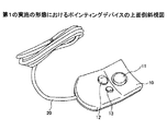
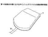
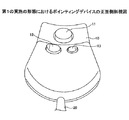
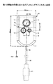
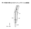
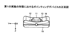
図1から図9に基づき、本実施の形態におけるポインティングデバイスについて説明する。図1は本実施の形態におけるポインティングデバイスの上面側斜視図を示し、図2は裏面側斜視図を示し、図3は正面側斜視図を示す。また、図4には本実施の形態におけるポインティングデバイスの上面図を示し、図5には側面図を示し、図6は正面図を示し、図7は、図4における破線7A−7Bにおいて切断した断面図を示す。
A pointing device according to the present embodiment will be described with reference to FIGS. 1 shows a top perspective view of the pointing device according to the present embodiment, FIG. 2 shows a back side perspective view, and FIG. 3 shows a front side perspective view. 4 shows a top view of the pointing device in this embodiment, FIG. 5 shows a side view, FIG. 6 shows a front view, and FIG. 7 is cut along a
本実施の形態におけるポインティングデバイスは、本体部10に、カーソル操作子11と、クリック操作子12及び13を有している。
The pointing device in the present embodiment has a
本体部10は、全体が屈曲部14において、本体部10の表面部18側に、くの字状に曲げ角θで曲げられた構造となっており、屈曲部14を境界として本体上部15と本体下部16とが形成されている。本実施の形態では、本体部10は、長さが約80mm、幅が約50mmで形成されている。また、本体下部16には接続コード20が接続されており、接続コード20の端部には接続端子21が設けられ、不図示のパーソナルコンピュータ等と接続することができるように構成されている。本体下部16において接続コード20が接続されている手前側領域17は、接続コード20側に凸の曲線形状となるように形成されている。
The
また、本体部10の表面部18は、本体部10の表面における中央部分が凹んだ形状の曲面により形成されている。これは、表面部18における形状を人の親指の形状に対応させたものであり、人の親指の動きを妨げることなく、かつ、なじみやすい形状となっている。一方、本体部10の裏面部19は、平らに形成されており、裏面部19の表面には滑り止め処理がなされている。具体的には、滑り止め処理として、ゴム等の材料の塗装がなされている。また、本体部10は、ABS樹脂等の樹脂材料により形成されており、本体部10に触れた感触が手に違和感なくなじむように、本体部10の表面には、シボ加工またはエンボス加工が施されている。
Further, the
カーソル操作子11は、本体上部15の表面部18に設けられており、カーソル操作子11において上下左右(4方向)の2次元方向の向きに力を加えることにより、不図示のパーソナルコンピュータの画面上に表示されるポインタまたはカーソルを上下左右の2次元方向に移動させることができるものである。
The
クリック操作子12及び13は、本体下部16の表面部18に並んで設けられており、マウス等における右クリック操作及び左クリック操作を行うことができるものであり、クリック操作子12及びクリック操作子13を押すことにより、左クリック及び右クリックの操作がなされる。
The
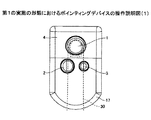
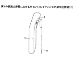
本実施の形態におけるポインティングデバイスは、図8及び図9に示されるように、本体部10の表面部18側において人の親指30により操作するものである。この際、カーソル操作子11は、親指30の指先部分と接触し、親指30の指先部分により操作がなされる。クリック操作子12は、親指30の腹の部分を左側に移動させるか、または親指30の腹の部分により左側に力を加えることによりクリック操作がされるように構成されている。また、クリック操作子13は、親指30の腹の部分を右側に移動させるか、または親指30の腹の部分により右側に力を加えることによりクリック操作がされるように構成されている。尚、本実施の形態におけるポインティングデバイスは、下方向(図6等に示す+Z方向)に力を加えることによってもクリック操作を行うことが可能である。
As shown in FIGS. 8 and 9, the pointing device in the present embodiment is operated by a
このため、図9に示すように、本実施の形態におけるポインティングデバイスは、人の親指の形状になじみやすいように、本体部10は屈曲部14において、表面部18側に曲げ角θにより曲げられた構造となっている。即ち、本体下部16の表面に対し本体上部15の表面は曲げ角θで折曲げられた構造となっている。曲げ角θは、人の親指の指先部分の形状になじむような角度であることが好ましく、具体的には、5°から25°が好ましく、より好ましくは、10°から21°、さらに好ましくは、15°から21°である。本実施の形態では、角度θは約18°となるように形成されている。
For this reason, as shown in FIG. 9, in the pointing device according to the present embodiment, the
また、本実施の形態におけるポインティングデバイスは、人の親指により、カーソル操作子11及びクリック操作子12、13を操作するものであることから、配置等は制限される。即ち、カーソル操作子11は親指の指先により操作され、クリック操作子12及び13は親指の腹の部分により操作される。このためクリック操作子12及び13の中心は、同じY軸上となるよう配置されており、カーソル操作子11の中心から略同じ距離に形成されていることが好ましい。言い換えれば、カーソル操作子11の中心とクリック操作子12及び13の各々の中心とを線で結んだ形状が、図4に示す二点鎖線Aに示すように、二等辺三角形となるように形成されていることが好ましい。また、本体部10の形状は、親指の伸びる方向を軸として、左右対称に形成されていることが好ましい。
In addition, since the pointing device in the present embodiment operates the
また、クリック操作子12及び13の中心からカーソル操作子11の中心までにおいて、親指の伸びる方向の長さ、即ち、X方向における長さaは、16mmから24mmが好ましく、更には、16mmから22mmが好ましい。このため本実施の形態では、長さaは約19mmとなるように形成されている。また、クリック操作子12の中心とクリック操作子13の中心との距離bは人の親指の腹の部分により操作がされるため、人の親指の幅の前後の値であることが好ましい。このため距離bは、11mmから21mmであることが好ましく、更には、13mmから19mmであることが好ましい。よって、本実施の形態では、距離bは約16mmとなるように形成されている。
The length in the direction in which the thumb extends from the center of the
次に、クリック操作子12及び13について説明する。上述したようにクリック操作子12及び13は、人の親指30の腹の部分を移動させるか、または人の親指30の腹の部分により力を加えることにより操作される。このためクリック操作子12の表面は、本体部10の表面部18において、表面における中央部分が凹んだ形状の曲面に対し、親指の伸びる方向に対し垂直方向(+Y軸方向)における外側部分が出っ張った形状となっている。
Next, the
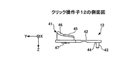
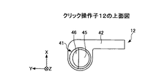
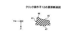
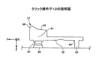
図10から図13に基づき、クリック操作子12について説明する。図13に示すように、クリック操作子12は、スイッチ部品40の直上に設けられたキートップ41と、キートップ41に接続されたヒンジ42を有している。ヒンジ42は固定部43に接続部分44において接続されており、キートップ41の裏面、即ち、スイッチ部品40が設けられている側の面には、スイッチ部品40に接触し押下するための接触部47が設けられている。また、キートップ41の表面45は、外側方向から中央方向に向かって、下方向に傾斜した構造、即ち、+Y方向から−Y方向に向かって、+Z方向に傾斜した構造となっている。また、キートップ41の表面45は+Y方向側において−Z方向に出っ張った形状の出っ張り部46を有している。
The
キートップ41の表面45の形状を本体下部16における凹面の曲面の表面よりも、+Y方向側において−Z方向に出っ張った形状の出っ張り部46を有することにより、図13に示すように、親指の腹の部分によりキートップ41の表面45において、+Y方向に力を加えた場合、接続部分44を動作支点としてヒンジ42が撓み、キートップ41の全体の位置が+Z方向に変位する。これによりキートップ41の下方に設けられた接触部47が、スイッチ部品40に接触しスイッチ部品40を押下し、クリック操作がなされる。
As shown in FIG. 13, the
このためクリック操作子12では、+Z方向に力を加えることなく、+Y方向に加える力のみで、キートップ41の位置を+Z方向に変位させることができ、クリック操作を行うことができる。即ち、親指により押す等の動作をすることなく、親指の腹の部分を傾けるか、または移動させる動作によりクリック操作を行うことができる。よって、親指の微動な操作により左クリック操作を行うことができる。尚、本実施の形態におけるポインティングデバイスでは、+Z方向に力を加えることによっても、上記クリック操作を行うことが可能である。
For this reason, in the
また、クリック操作子13の表面は、クリック操作子12と同様に、本体部10の表面部18において、表面における中央部分が凹んだ形状の曲面に対し、親指の伸びる方向に対し垂直方向(−Y軸方向)における外側部分が出っ張った形状となっている。
Similarly to the
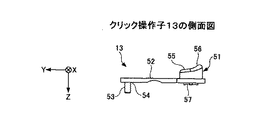
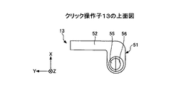
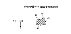
図14から図16に基づき、クリック操作子13について説明する。クリック操作子12と同様に、クリック操作子13は、不図示のスイッチ部品の直上に設けられたキートップ51と、キートップ51に接続されたヒンジ52を有している。ヒンジ52は固定部53に接続部分54において接続されており、キートップ51の裏面、即ち、スイッチ部品が設けられている面には、スイッチ部品に接触し押下するための接触部57が設けられている。また、キートップ51の表面55は、外側方向から中央方向に向かって、下方向に傾斜した構造、即ち、−Y方向から+Y方向に向かって、+Z方向に傾斜した構造となっている。また、キートップ51の表面55は−Y方向側において−Z方向に出っ張った形状の出っ張り部56を有している。
The
クリック操作子13もクリック操作子12と同様に、親指の腹の部分を傾けるか、または移動させる動作によりクリック操作を行うことができる。よって、親指の微動な操作により右クリック操作を行うことができる。
Similarly to the
以上より、本実施の形態におけるポインティングデバイスでは、親指一本の微細な操作により、カーソル操作及び2つのクリック操作を容易に行うことができ、操作性を向上させることができる。 As described above, in the pointing device according to the present embodiment, the cursor operation and the two click operations can be easily performed by a minute operation of one thumb, and the operability can be improved.
〔第2の実施の形態〕
次に、第2の実施の形態について説明する。本実施の形態におけるポインティングデバイスは、第1の実施の形態におけるポインティングデバイスと、クリック操作子の形状が異なるものである。
[Second Embodiment]
Next, a second embodiment will be described. The pointing device in the present embodiment is different from the pointing device in the first embodiment in the shape of the click operator.
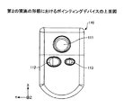
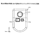
図17に基づき、本実施の形態におけるポインティングデバイスについて説明する。 The pointing device in the present embodiment will be described based on FIG.
本実施の形態におけるポインティングデバイスは、本体部110に、カーソル操作子111と、クリック操作子112及び113を有している。本実施の形態におけるクリック操作子112及び113の形状は長円形または楕円形の形状で形成されている。クリック操作子112及び113における長円形または楕円形は、不図示の親指の伸びる方向である+X方向に対して垂直方向、即ち、Y方向が長径となるように配置されている。このような形状でクリック操作子112及び113を形成することにより、親指の太さの違いにより操作性に差が出ることを防ぐことができる。即ち、親指の太さに依存することなく、誰でも快適にポインティングデバイスの操作を行うことができる。
The pointing device in the present embodiment includes a
また、クリック操作子は、その他の多角形状の形状で形成することも可能である。例えば、図18に示すように、親指の伸びる方向である+X方向に対して垂直方向、即ち、Y方向が長辺となる長方形の形状にクリック操作子112a及び113aを形成することにより、より親指の太さに依存することなく、誰でも快適にポインティングデバイスの操作を行うことができる。
Further, the click operator can be formed in other polygonal shapes. For example, as shown in FIG. 18, the
尚、本実施の形態における本体部110、カーソル操作子111、クリック操作子112、112a及び113、113aは、第1の実施の形態における本体部10、カーソル操作子11、クリック操作子12及び13と同一の機能を有するものであり、上記以外の内容については、第1の実施の形態と同様である。
The
〔第3の実施の形態〕
次に、第3の実施の形態について説明する。本実施の形態におけるポインティングデバイスは、ワイヤレス構造のポインティングデバイスである。
[Third Embodiment]
Next, a third embodiment will be described. The pointing device in this embodiment is a wireless-structured pointing device.
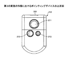
図19に基づき本実施の形態におけるポインティングデバイスについて説明する。本実施の形態におけるポインティングデバイスは、本体部210に、カーソル操作子211と、クリック操作子212及び213、無線送信部260を有している。
The pointing device in the present embodiment will be described based on FIG. The pointing device according to the present embodiment includes a
無線送信部260は、赤外線等の無線通信により、不図示のパーソナルコンピュータに設けられた無線受信部との間で、情報の通信を行うためのものである。無線送信部260は、カーソル操作子211の設けられている本体上部の端部に設けられていることが好ましい。操作を行う際の手等により通信が妨げられることがないからである。このような構成にすることにより、より一層、操作環境に制限されることなく快適にポインティングデバイスの操作を行うことができる。
The
尚、本実施の形態における本体部210、カーソル操作子211、クリック操作子212及び213は、第1の実施の形態における本体部10、カーソル操作子11、クリック操作子12及び13と同一の機能を有するものであり、上記以外の内容については、第1の実施の形態と同様である。
Note that the main body 210, the
以上、本発明の実施に係る形態について説明したが、上記内容は、発明の内容を限定するものではない。 As mentioned above, although the form which concerns on implementation of this invention was demonstrated, the said content does not limit the content of invention.
10 本体部
11 カーソル操作子
12 クリック操作子
13 クリック操作子
14 屈曲部
15 本体上部
16 本体下部
17 手前側領域
18 表面部
19 裏面部
20 接続コード
30 親指
40 スイッチ部品
41、51 キートップ
42、52 ヒンジ
43、53 固定部
44、54 接続部分
45、55 表面
46、56 出っ張り部
47、57 接触部
DESCRIPTION OF
Claims (10)
前記本体上部の表面に設けられている二次元方向の位置情報を入力するためのカーソル操作子と、
前記本体下部の表面に設けられているクリック操作を行うための2つのクリック操作子と、
を有することを特徴とするポインティングデバイス。 A body portion having a structure in which a central portion of the surface is formed by a curved surface having a concave shape, and is bent into a body upper portion and a body lower portion on the surface side at a bent portion;
A cursor operator for inputting position information in a two-dimensional direction provided on the upper surface of the main body;
Two click operators for performing a click operation provided on the lower surface of the main body;
A pointing device comprising:
Priority Applications (1)
| Application Number | Priority Date | Filing Date | Title |
|---|---|---|---|
| JP2009282581A JP5264692B2 (en) | 2009-12-14 | 2009-12-14 | pointing device |
Applications Claiming Priority (1)
| Application Number | Priority Date | Filing Date | Title |
|---|---|---|---|
| JP2009282581A JP5264692B2 (en) | 2009-12-14 | 2009-12-14 | pointing device |
Publications (2)
| Publication Number | Publication Date |
|---|---|
| JP2011123787A true JP2011123787A (en) | 2011-06-23 |
| JP5264692B2 JP5264692B2 (en) | 2013-08-14 |
Family
ID=44287597
Family Applications (1)
| Application Number | Title | Priority Date | Filing Date |
|---|---|---|---|
| JP2009282581A Active JP5264692B2 (en) | 2009-12-14 | 2009-12-14 | pointing device |
Country Status (1)
| Country | Link |
|---|---|
| JP (1) | JP5264692B2 (en) |
Citations (4)
| Publication number | Priority date | Publication date | Assignee | Title |
|---|---|---|---|---|
| JPH0635598A (en) * | 1992-07-13 | 1994-02-10 | Alps Electric Co Ltd | X-y direction input device |
| JPH06318134A (en) * | 1994-03-15 | 1994-11-15 | Les-Ben:Kk | Data input device |
| JP2007200228A (en) * | 2006-01-30 | 2007-08-09 | Wacom Co Ltd | POSITION INPUT DEVICE, REMOTE CONTROL DEVICE, AND REMOTE OPERATION SYSTEM |
| JP2007200188A (en) * | 2006-01-30 | 2007-08-09 | Wacom Co Ltd | Position input device, remote control device, computer system, and electronic device |
-
2009
- 2009-12-14 JP JP2009282581A patent/JP5264692B2/en active Active
Patent Citations (4)
| Publication number | Priority date | Publication date | Assignee | Title |
|---|---|---|---|---|
| JPH0635598A (en) * | 1992-07-13 | 1994-02-10 | Alps Electric Co Ltd | X-y direction input device |
| JPH06318134A (en) * | 1994-03-15 | 1994-11-15 | Les-Ben:Kk | Data input device |
| JP2007200228A (en) * | 2006-01-30 | 2007-08-09 | Wacom Co Ltd | POSITION INPUT DEVICE, REMOTE CONTROL DEVICE, AND REMOTE OPERATION SYSTEM |
| JP2007200188A (en) * | 2006-01-30 | 2007-08-09 | Wacom Co Ltd | Position input device, remote control device, computer system, and electronic device |
Also Published As
| Publication number | Publication date |
|---|---|
| JP5264692B2 (en) | 2013-08-14 |
Similar Documents
| Publication | Publication Date | Title |
|---|---|---|
| EP2156274B1 (en) | Touch-sensitive pointing device with guiding lines | |
| JP4029410B2 (en) | Input device with fingertip wearing sensor | |
| US9063587B2 (en) | Computer input device with ergonomically formed and positioned actuators | |
| US10928908B2 (en) | Haptic device, for interaction with virtual reality or augmented reality systems | |
| US6147673A (en) | Computer input device and keyboard | |
| US7006075B1 (en) | Ergonomic computer mouse | |
| TWI291120B (en) | Ergonomically shaped computer pointing device and computer mouse | |
| US6549189B1 (en) | Method for operating a computer input device and keyboard | |
| JP4931616B2 (en) | Input aid | |
| TWI499942B (en) | Swinging type mouse | |
| JP2012168869A (en) | Portable terminal and key operation device | |
| JP6419994B2 (en) | Method and data input device for inputting data in electrical form | |
| TWM325555U (en) | Improved mouse | |
| JP5264692B2 (en) | pointing device | |
| WO2006045209A3 (en) | Input device | |
| US20070201932A1 (en) | Digit-operated input device | |
| US20180074604A1 (en) | Flat mouse and usage method thereof | |
| Curic et al. | Keyboard mouse glove with Bluetooth capabilities for the physically impaired | |
| CN103376886A (en) | Cursor control device | |
| JP2012079097A (en) | Information apparatus with key input unit disposed on surface invisible during use, input method and program | |
| US20050099392A1 (en) | Mouse having scrolling function | |
| US8446362B2 (en) | Hand-shaped mouse | |
| JP3215538U (en) | Mouse device | |
| CN211827215U (en) | Bluetooth-based keyboard and mouse integrated handheld input device | |
| JP2014164428A (en) | Pointing device and pointer operation method |
Legal Events
| Date | Code | Title | Description |
|---|---|---|---|
| A621 | Written request for application examination |
Free format text: JAPANESE INTERMEDIATE CODE: A621 Effective date: 20121012 |
|
| A711 | Notification of change in applicant |
Free format text: JAPANESE INTERMEDIATE CODE: A711 Effective date: 20121012 |
|
| RD02 | Notification of acceptance of power of attorney |
Free format text: JAPANESE INTERMEDIATE CODE: A7422 Effective date: 20121012 |
|
| RD04 | Notification of resignation of power of attorney |
Free format text: JAPANESE INTERMEDIATE CODE: A7424 Effective date: 20121015 |
|
| A521 | Request for written amendment filed |
Free format text: JAPANESE INTERMEDIATE CODE: A821 Effective date: 20121012 |
|
| TRDD | Decision of grant or rejection written | ||
| A977 | Report on retrieval |
Free format text: JAPANESE INTERMEDIATE CODE: A971007 Effective date: 20130424 |
|
| A01 | Written decision to grant a patent or to grant a registration (utility model) |
Free format text: JAPANESE INTERMEDIATE CODE: A01 Effective date: 20130430 |
|
| A61 | First payment of annual fees (during grant procedure) |
Free format text: JAPANESE INTERMEDIATE CODE: A61 Effective date: 20130430 |
|
| R150 | Certificate of patent or registration of utility model |
Ref document number: 5264692 Country of ref document: JP Free format text: JAPANESE INTERMEDIATE CODE: R150 Free format text: JAPANESE INTERMEDIATE CODE: R150 |
|
| R250 | Receipt of annual fees |
Free format text: JAPANESE INTERMEDIATE CODE: R250 |
|
| R250 | Receipt of annual fees |
Free format text: JAPANESE INTERMEDIATE CODE: R250 |
|
| R250 | Receipt of annual fees |
Free format text: JAPANESE INTERMEDIATE CODE: R250 |
|
| R250 | Receipt of annual fees |
Free format text: JAPANESE INTERMEDIATE CODE: R250 |
|
| R250 | Receipt of annual fees |
Free format text: JAPANESE INTERMEDIATE CODE: R250 |
|
| R250 | Receipt of annual fees |
Free format text: JAPANESE INTERMEDIATE CODE: R250 |
|
| R250 | Receipt of annual fees |
Free format text: JAPANESE INTERMEDIATE CODE: R250 |
|
| R250 | Receipt of annual fees |
Free format text: JAPANESE INTERMEDIATE CODE: R250 |
|
| R250 | Receipt of annual fees |
Free format text: JAPANESE INTERMEDIATE CODE: R250 |
|
| R250 | Receipt of annual fees |
Free format text: JAPANESE INTERMEDIATE CODE: R250 |
|
| R250 | Receipt of annual fees |
Free format text: JAPANESE INTERMEDIATE CODE: R250 |