JP2011123783A - Device, method and program for generating simulated fault, and test system - Google Patents
Device, method and program for generating simulated fault, and test system Download PDFInfo
- Publication number
- JP2011123783A JP2011123783A JP2009282462A JP2009282462A JP2011123783A JP 2011123783 A JP2011123783 A JP 2011123783A JP 2009282462 A JP2009282462 A JP 2009282462A JP 2009282462 A JP2009282462 A JP 2009282462A JP 2011123783 A JP2011123783 A JP 2011123783A
- Authority
- JP
- Japan
- Prior art keywords
- data
- frame
- unit
- failure
- fault
- Prior art date
- Legal status (The legal status is an assumption and is not a legal conclusion. Google has not performed a legal analysis and makes no representation as to the accuracy of the status listed.)
- Pending
Links
Images
Landscapes
- Test And Diagnosis Of Digital Computers (AREA)
Abstract
【課題】2つの装置間で送受信されるデータの内容に応じて擬似的に障害を発生させる。
【解決手段】サーバとディスクとの間に接続された障害シミュレータ11において、データ保存部A111は、データ受信部A101によりサーバから受信されたデータを複データ保持部172に順次保存する。コマンド解析部141は、複データ保持部172に保存されている、最先のデータから1フレーム分のデータを解析して、当該1フレーム分のデータが特定のコマンドであるかどうかを判定する。特定のコマンドでなければ、制御部131は複データ保持部172から最先のデータを取り出してデータ送信部A102によりディスクA14へ送信する。特定のコマンドであれば、制御部131は予め定められた時間が経過するまで待機してから当該1フレーム分のデータをデータ送信部A102によりディスクA14へ送信することで擬似障害を発生させる。
【選択図】図2A pseudo failure is generated according to the contents of data transmitted and received between two devices.
In a failure simulator connected between a server and a disk, a data storage unit A111 sequentially stores data received from the server by a data receiving unit A101 in a multiple data holding unit 172. The command analysis unit 141 analyzes data for one frame from the earliest data stored in the multiple data holding unit 172, and determines whether the data for one frame is a specific command. If it is not a specific command, the control unit 131 retrieves the earliest data from the multiple data holding unit 172 and transmits it to the disk A14 by the data transmission unit A102. If the command is a specific command, the control unit 131 waits until a predetermined time elapses, and then transmits the data for one frame to the disk A14 by the data transmission unit A102, thereby generating a pseudo failure.
[Selection] Figure 2
Description
本発明は、擬似障害発生装置及び擬似障害発生方法及び擬似障害発生プログラム及び試験システムに関するものである。本発明は、特に、高信頼性システム向け試験システムに関するものである。 The present invention relates to a simulated fault generation apparatus, a simulated fault generation method, a simulated fault generation program, and a test system. The present invention particularly relates to a test system for a high reliability system.
システムの信頼性を高めるためにコンポーネントを冗長化し、二重系システムを構築することが多い。ホットスタンバイ方式では、1台が主系として業務を処理し、もう1台は従系として待機する。主系で障害が発生すると、系の切り替え機構が動作して、従系において業務を処理するようになる。この結果、障害が発生してもMTTR(Mean・Time・To・Repair:平均復旧時間)を短くすることができ信頼性の高いシステムを実現できる。 In order to increase system reliability, redundant components are often used to construct a dual system. In the hot standby system, one unit processes a job as a primary system, and the other unit stands by as a secondary system. When a failure occurs in the primary system, the system switching mechanism operates to process the business in the secondary system. As a result, even if a failure occurs, MTTR (Mean Time Time To Repair: average recovery time) can be shortened and a highly reliable system can be realized.
ところで主系から従系への系切り替えの試験は、障害を発生させる必要があるため、試験を行うのは難しい。システムをフルカスタムで構成すれば、デバイスドライバ、ミドルウェアに障害モードを作り、ソフトウェア的に障害が発生したことを模擬することができ、容易に系切り替え試験を行うことができる。しかし実際は、IHV(Independent・Hardware・Vendor)製品、ISV(Independent・Software・Vendor)製品といったサードパーティの提供する製品を活用しながらシステムを組むために上記のような方法を取ることは難しく、細かい条件の障害を発生させることができていない。この結果、十分な試験を行えずに二重系システムの系切り替えを失敗し、二重系システムでありながらシステムがダウンするようなことが起こる。 By the way, the system switching test from the main system to the subordinate system is difficult to test because it is necessary to generate a failure. If the system is fully custom configured, a failure mode can be created in the device driver and middleware to simulate the occurrence of a failure in software, and a system switching test can be easily performed. However, in reality, it is difficult to take the above-mentioned method to build a system while utilizing products provided by third parties such as IHV (Independent, Hardware, Vendor) products and ISV (Independent, Software, Vendor) products. Can not cause any failure. As a result, the system switching of the dual system fails due to insufficient testing, and the system goes down even though it is a dual system.
ケーブルやバックボードを介して接続するコンポーネントの障害について特許文献1では、コンポーネント間に障害を模擬するような障害シミュレータを設置することであたかも故障が起こったように見せかける方法が開示されている。また、特許文献2では、ディスクアレイ装置内の障害模擬機能において、送受信するデータを停止することにより障害を模擬することが開示されている。
Regarding a failure of a component connected via a cable or a backboard,
上記の通り、ミッションクリティカルなシステムでは、二重系システムを構築し高い信頼性を実現する。二重系システムにおいても障害は発生するが、中でもストレージに関するものが多く見られる。そこで、系切り替えの品質を高めるために、ストレージに関する試験を充実させる必要がある。ストレージでは、故障してしまいまったく応答しなくなる障害から、「応答遅延」が大きくなるものや、リトライすれば救われるような現象でも程度の差により障害と見られるものまで、いろいろなレベルでの障害が起こる。しかし現状ではケーブルを抜いたり、電源オフしたりするしか障害を模擬する方法がなく、十分な試験を行えていないという課題がある。従来の障害シミュレータを設置しても、回線上を転送されてくるデータを解析する手段がないので、ディスクの特定のエリアにアクセスする場合に発生する障害を模擬することはできないという課題がある。 As described above, in mission-critical systems, a dual system is constructed to achieve high reliability. Even in a dual system, a failure occurs, but there are many related to storage. Therefore, in order to improve the quality of system switching, it is necessary to enhance tests related to storage. In storage, failures at various levels, from failures that fail and do not respond at all, to those that have a large “response delay”, and those that can be saved by retrying, but appear to be failures due to varying degrees Happens. However, at present, there is only a method of simulating a failure by pulling out a cable or turning off the power, and there is a problem that a sufficient test cannot be performed. Even if a conventional failure simulator is installed, there is no means for analyzing the data transferred on the line, so that there is a problem that a failure that occurs when accessing a specific area of the disk cannot be simulated.
本発明は、例えば、2つの装置間で送受信されるデータの内容に応じて擬似的に障害を発生させることを目的とする。また、本発明は、例えば、障害レベルや障害発生タイミングを細かく調節することを目的とする。また、本発明は、例えば、二重系システム等の品質を高めるためにきめ細やかな試験を行うことを目的とする。 For example, an object of the present invention is to cause a pseudo failure according to the contents of data transmitted and received between two devices. Another object of the present invention is to finely adjust, for example, the failure level and failure occurrence timing. Another object of the present invention is to conduct detailed tests in order to improve the quality of, for example, a dual system.
本発明の一の態様に係る擬似障害発生装置は、
複数のデータで構成されたフレームを送信する送信装置と、当該フレームを受信する受信装置との間に接続され、当該フレームを用いた通信における擬似障害を発生させる擬似障害発生装置であって、
前記送信装置からデータを受信するデータ受信部と、
前記受信装置へデータを送信するデータ送信部と、
前記データ受信部により受信されたデータをバッファメモリに順次保存するデータ保存部と、
前記データ保存部により前記バッファメモリに保存されている、最先のデータから1フレーム分のデータを解析して当該1フレーム分のデータが所定のフレームであるかどうかを判定するデータ判定部と、
前記データ判定部により解析された1フレーム分のデータが前記所定のフレームでないと判定された場合、前記バッファメモリから最先のデータを取り出して前記データ送信部に送信させ、前記データ判定部により当該1フレーム分のデータが前記所定のフレームであると判定された場合、前記擬似障害を発生させる制御部とを備えることを特徴とする。
A simulated fault generating apparatus according to one aspect of the present invention includes:
A pseudo failure generator that is connected between a transmitting device that transmits a frame composed of a plurality of data and a receiving device that receives the frame, and generates a pseudo failure in communication using the frame,
A data receiver for receiving data from the transmitter;
A data transmission unit for transmitting data to the receiving device;
A data storage unit for sequentially storing data received by the data receiving unit in a buffer memory;
A data determination unit that analyzes data for one frame from the earliest data stored in the buffer memory by the data storage unit and determines whether the data for the one frame is a predetermined frame;
When it is determined that the data for one frame analyzed by the data determination unit is not the predetermined frame, the earliest data is extracted from the buffer memory and transmitted to the data transmission unit, and the data determination unit And a controller that generates the pseudo failure when it is determined that the data for one frame is the predetermined frame.
本発明の一の態様において、送信装置と受信装置との間に接続された擬似障害発生装置のデータ保存部は、送信装置からのデータをバッファメモリに順次保存する。擬似障害発生装置のデータ判定部は、データ保存部によりバッファメモリに保存されている、最先のデータから1フレーム分のデータを解析して当該1フレーム分のデータが所定のフレームであるかどうかを判定する。データ判定部により解析された1フレーム分のデータが所定のフレームでないと判定された場合、擬似障害発生装置の制御部は、バッファメモリから最先のデータを取り出してデータ送信部に送信させる。一方、データ判定部により当該1フレーム分のデータが所定のフレームであると判定された場合、制御部は、擬似障害を発生させる。このため、送信装置と受信装置との間で送受信されるフレームの内容に応じて擬似的に障害を発生させることが可能となる。 In one aspect of the present invention, the data storage unit of the simulated fault occurrence device connected between the transmission device and the reception device sequentially stores data from the transmission device in the buffer memory. The data determination unit of the simulated fault generator analyzes the data for one frame from the earliest data stored in the buffer memory by the data storage unit, and determines whether the data for the one frame is a predetermined frame Determine. When it is determined that the data for one frame analyzed by the data determination unit is not a predetermined frame, the control unit of the pseudo-fault generating device extracts the earliest data from the buffer memory and causes the data transmission unit to transmit it. On the other hand, when the data determination unit determines that the data for one frame is a predetermined frame, the control unit generates a pseudo failure. For this reason, it becomes possible to cause a pseudo failure according to the content of the frame transmitted and received between the transmission device and the reception device.
以下、本発明の実施の形態について、図を用いて説明する。 Hereinafter, embodiments of the present invention will be described with reference to the drawings.
実施の形態1.
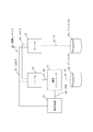
図1は、本実施の形態に係る試験システム10の構成を示すブロック図である。
FIG. 1 is a block diagram showing a configuration of a test system 10 according to the present embodiment.
図1において、試験システム10は、障害シミュレータ11、サーバA12、サーバB13、ディスクA14、ディスクB15、検証端末16を備える。障害シミュレータ11、サーバA12、サーバB13、ディスクA14、ディスクB15は、いずれもFC(ファイバチャネル)のコンポーネントとなっている。障害シミュレータ11とサーバA12は、FC17で接続されている。障害シミュレータ11とディスクA14は、FC18で接続されている。サーバB13とディスクB15は、FC19で接続されている。サーバA12とサーバB13は、LAN_A20(ローカルエリアネットワーク)で接続されている。また、サーバA12とサーバB13は、検証端末16にLAN_B21(ローカルエリアネットワーク)で接続されている。検証端末16は、障害シミュレータ11とUSB22(Universal・Serial・Bus)で接続されている。
1, the test system 10 includes a
試験システム10は、主としてサーバA12とサーバB13で構成された二重系システムにおいて、障害シミュレータ11を使用して、障害を模擬的に起こして系切り替えの試験を実施する。サーバA12は主系であり業務処理を行う。サーバB13は従系でありサーバA12に障害が発生したとき(例えば、サーバA12の故障時)に業務処理を継続するために待機している。サーバA12及びサーバB13間の系切り替え等の二重系処理は、サーバA12及びサーバB13上で動作する二重系制御プログラムが行う。
The test system 10 uses a
障害シミュレータ11が模擬できる障害(擬似障害)の分類(障害タイプ)としては、以下のようなものがある。
(1)「応答遅延」:サーバからのコマンドに対してディスクからの応答が遅れる。
(2)「無応答」:サーバからのコマンドに対してディスクからの応答がない。
(3)「リンク断」:コンポーネント間の接続の同期が取れなくなる。
(4)「応答異常」:ディスクからの応答に異常が発生する。具体的には、CRC(Cyclic・Redundancy・Check)エラーが発生する。
The following classifications (failure types) of faults (pseudo faults) that can be simulated by the
(1) “Response delay”: the response from the disk is delayed with respect to the command from the server.
(2) “No response”: There is no response from the disk to the command from the server.
(3) “Link break”: Connection between components cannot be synchronized.
(4) “Response error”: An error occurs in the response from the disk. Specifically, a CRC (Cyclic / Redundancy / Check) error occurs.
サーバA12は、複数のデータで構成されたフレームを送信する送信装置の一例である。ディスクA14は、このフレームを受信する受信装置の一例である。なお、サーバA12やディスクA14は、他の種類の装置(例えば、コンピュータ)に置き換えても構わない。本実施の形態では、フレームの一例としてファイバチャネルのフレームを用いているが、他の種類のフレームを用いてもよい。例えば、HDLC(High−Level・Data・Link・Control)のフレームを用いてもよい。また、複数のデータのかたまりであれば、フレーム以外のものを用いてもよい。障害シミュレータ11は、送信装置と受信装置との間に接続され、上記フレームを用いた通信における擬似障害を発生させる擬似障害発生装置の一例である。本実施の形態では、通信の一例としてファイバチャネルを用いているが、他の種類の通信でもよいことは前述した通りである。検証端末16は、擬似障害発生装置と接続され、試験の開始を指示する端末装置の一例である。
The server A12 is an example of a transmission device that transmits a frame composed of a plurality of data. The disk A14 is an example of a receiving device that receives this frame. The server A12 and the disk A14 may be replaced with other types of devices (for example, computers). In the present embodiment, a fiber channel frame is used as an example of a frame, but other types of frames may be used. For example, an HDLC (High-Level / Data / Link / Control) frame may be used. Further, as long as it is a group of a plurality of data, other than the frame may be used. The
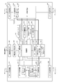
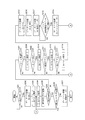
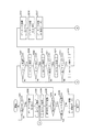
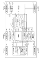
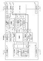
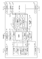
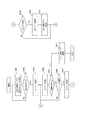
図2は、障害シミュレータ11の構成を示すブロック図である。
FIG. 2 is a block diagram showing a configuration of the
図2において、障害シミュレータ11は、データ受信部A101、データ送信部A102、データ送信部B103、データ受信部B104、データ保存部A111、データ保存部B112、制御部131、コマンド解析部141、データ解析部142、代替送信データ出力部151、データ選択部A152、データ選択部B153、データ置換部154、コマンド送信遅延タイマ161を備える。データ保存部A111は、単データ保持部171及び複データ保持部172を有する。データ送信部B103及びデータ受信部B104は、データ生成部の一例である。コマンド解析部141は、データ判定部の一例である。代替送信データ出力部151は、データ生成部の一例である。複データ保持部172は、バッファメモリの一例である。また、障害シミュレータ11は、検証端末I/F181(インタフェース)、障害注入設定部182、非IDLEフラグ191、受信データ数カウンタ192、D_ID保存部193を備える。障害シミュレータ11の各部の動作については後述する。
In FIG. 2, the
障害シミュレータ11において、ディスクA14へ送信されるデータのパスとしては、第1データ経路173、第2データ経路174、第3データ経路175の3つがある。これらのパスはデータ選択部A152によって選択的に使用される。第1データ経路173は、データ受信部A101によってサーバA12から受信されたデータが、単データ保持部171で一旦保存された後、複データ保持部172をバイパスしてデータ送信部A102によってそのままディスクA14へ送信されるパスである。第2データ経路174は、データ受信部A101によってサーバA12から受信されたデータが、単データ保持部171で一旦保存された後、複データ保持部172で暫く保持されてからデータ送信部A102によってディスクA14へ送信されるパスである。第3データ経路175は、代替送信データ出力部151によって生成されたデータが、データ送信部A102によってディスクA14へ送信されるパスである。
In the
障害シミュレータ11において、サーバA12へ送信されるデータのパスとしては、第4データ経路176、第5データ経路177の2つがある。詳細については後述するが、これらのパスはデータ選択部B153によって選択的に使用される。第4データ経路176は、データ受信部B104によってディスクA14から受信されたデータが、データ保存部B112で保存された後、データ送信部B103によってサーバA12へ送信されるパスである。第5データ経路177は、代替送信データ出力部151によって生成されたデータが、データ送信部B103によってサーバA12へ送信されるパスである。
In the
図2に示していないが、障害シミュレータ11は、処理装置、記憶装置、入力装置、出力装置等のハードウェアを具備する。ハードウェアは障害シミュレータ11の各部によって利用される。例えば、処理装置は、障害シミュレータ11の各部でデータや情報の演算、加工、読み取り、書き込み等を行うために利用される。記憶装置は、そのデータや情報を記憶するために利用される。また、入力装置は、そのデータや情報を入力するために、出力装置は、そのデータや情報を出力するために利用される。
Although not shown in FIG. 2, the
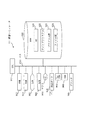
図3は、障害シミュレータ11のハードウェア構成の一例を示す図である。なお、障害シミュレータ11と同様に、サーバA12、サーバB13、検証端末16を、以下に示すようなハードウェア構成で実現しても構わない。
FIG. 3 is a diagram illustrating an example of a hardware configuration of the
図3において、障害シミュレータ11は、コンピュータであり、LCD901(Liquid・Crystal・Display)、キーボード902(K/B)、マウス903、FDD904(Flexible・Disk・Drive)、CDD905(Compact・Disc・Drive)、プリンタ906といったハードウェアデバイスを備えている。これらのハードウェアデバイスはケーブルや信号線で接続されている。LCD901の代わりに、CRT(Cathode・Ray・Tube)、あるいは、その他の表示装置が用いられてもよい。マウス903の代わりに、タッチパネル、タッチパッド、トラックボール、ペンタブレット、あるいは、その他のポインティングデバイスが用いられてもよい。
In FIG. 3, the
障害シミュレータ11は、プログラムを実行するCPU911(Central・Processing・Unit)を備えている。CPU911は、処理装置の一例である。CPU911は、バス912を介してROM913(Read・Only・Memory)、RAM914(Random・Access・Memory)、通信ボード915、LCD901、キーボード902、マウス903、FDD904、CDD905、プリンタ906、HDD920(Hard・Disk・Drive)と接続され、これらのハードウェアデバイスを制御する。HDD920の代わりに、フラッシュメモリ、光ディスク装置、メモリカードリーダライタ又はその他の記憶媒体が用いられてもよい。
The
RAM914は、揮発性メモリの一例である。ROM913、FDD904、CDD905、HDD920は、不揮発性メモリの一例である。これらは、記憶装置の一例である。通信ボード915、キーボード902、マウス903、FDD904、CDD905は、入力装置の一例である。また、通信ボード915、LCD901、プリンタ906は、出力装置の一例である。
The
通信ボード915は、LAN等に接続されている。通信ボード915は、LANに限らず、IP−VPN(Internet・Protocol・Virtual・Private・Network)、広域LAN、ATM(Asynchronous・Transfer・Mode)ネットワークといったWAN(ワイドエリアネットワーク)、あるいは、インターネットに接続されていても構わない。LAN、WAN、インターネットは、ネットワークの一例である。
The
HDD920には、オペレーティングシステム921(OS)、ウィンドウシステム922、プログラム群923、ファイル群924が記憶されている。プログラム群923のプログラムは、CPU911、オペレーティングシステム921、ウィンドウシステム922により実行される。プログラム群923には、本実施の形態の説明において「〜部」として説明する機能を実行するプログラムが含まれている。プログラムは、CPU911により読み出され実行される。ファイル群924には、本実施の形態の説明において、「〜データ」、「〜情報」、「〜ID(識別子)」、「〜フラグ」、「〜結果」として説明するデータや情報や信号値や変数値やパラメータが、「〜ファイル」や「〜データベース」や「〜テーブル」の各項目として含まれている。「〜ファイル」や「〜データベース」や「〜テーブル」は、RAM914やHDD920等の記憶媒体に記憶される。RAM914やHDD920等の記憶媒体に記憶されたデータや情報や信号値や変数値やパラメータは、読み書き回路を介してCPU911によりメインメモリやキャッシュメモリに読み出され、抽出、検索、参照、比較、演算、計算、制御、出力、印刷、表示といったCPU911の処理(動作)に用いられる。抽出、検索、参照、比較、演算、計算、制御、出力、印刷、表示といったCPU911の処理中、データや情報や信号値や変数値やパラメータは、メインメモリやキャッシュメモリやバッファメモリに一時的に記憶される。
The
本実施の形態の説明において用いるブロック図やフローチャートの矢印の部分は主としてデータや信号の入出力を示す。データや信号は、RAM914等のメモリ、FDD904のフレキシブルディスク(FD)、CDD905のコンパクトディスク(CD)、HDD920の磁気ディスク、光ディスク、DVD(Digital・Versatile・Disc)、あるいは、その他の記録媒体に記録される。また、データや信号は、バス912、信号線、ケーブル、あるいは、その他の伝送媒体により伝送される。
The arrows in the block diagrams and flowcharts used in the description of this embodiment mainly indicate input / output of data and signals. Data and signals are recorded in memory such as
本実施の形態の説明において「〜部」として説明するものは、「〜回路」、「〜装置」、「〜機器」であってもよく、また、「〜ステップ」、「〜工程」、「〜手順」、「〜処理」であってもよい。即ち、「〜部」として説明するものは、ROM913に記憶されたファームウェアで実現されていても構わない。あるいは、「〜部」として説明するものは、ソフトウェアのみ、あるいは、素子、デバイス、基板、配線といったハードウェアのみで実現されていても構わない。あるいは、「〜部」として説明するものは、ソフトウェアとハードウェアとの組み合わせ、あるいは、ソフトウェアとハードウェアとファームウェアとの組み合わせで実現されていても構わない。ファームウェアとソフトウェアは、プログラムとして、フレキシブルディスク、コンパクトディスク、磁気ディスク、光ディスク、DVD等の記録媒体に記憶される。プログラムはCPU911により読み出され、CPU911により実行される。即ち、プログラムは、本実施の形態の説明で述べる「〜部」としてコンピュータを機能させるものである。あるいは、プログラムは、本実施の形態の説明で述べる「〜部」の手順や方法をコンピュータに実行させるものである。
In the description of the present embodiment, what is described as “to part” may be “to circuit”, “to device”, “to device”, and “to step”, “to process”, “to”. ~ Procedure "," ~ process ". That is, what is described as “˜unit” may be realized by firmware stored in the
上記のように、本実施の形態では、障害シミュレータ11を、CPU911(処理装置の一例)を具備するコンピュータで実現しているが、障害シミュレータ11を、CPU911を具備しない専用のハードウェアで実現しても構わない。
As described above, in this embodiment, the
試験システム10は、前述したように、模擬的に障害を発生させて、業務処理を行うサーバをサーバA12からサーバB13に切り替えられることを確認する試験を行う。きめ細かい試験を行うためには、特定のコマンドを対象にして擬似的な障害を発生させる、あるいは、特定のディスクエリアへのアクセスを対象にして擬似的な障害を発生させる等、障害注入の対象を限定することが必要である。 As described above, the test system 10 performs a test for confirming that a server that performs business processing can be switched from the server A12 to the server B13 by generating a failure in a simulated manner. In order to conduct a detailed test, the target of fault injection, such as generating a pseudo fault for a specific command or generating a pseudo fault for access to a specific disk area, is selected. It is necessary to limit.
以下では、特定のコマンドを対象にして擬似的な障害を発生させる方法について、障害タイプ「応答遅延」を例に説明する。 In the following, a method of generating a pseudo failure for a specific command will be described by taking the failure type “response delay” as an example.
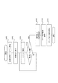
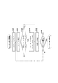
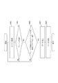
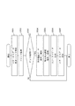
図4は、試験システム10の動作(本実施の形態に係る試験方法)を示すフローチャートである。 FIG. 4 is a flowchart showing the operation of the test system 10 (the test method according to the present embodiment).
図4において、障害発生に伴う系切り替え試験を開始するにあたり、サーバA12は、サーバA12からディスクA14にアクセスする処理を含む業務処理プログラムを起動する(ステップS101)。このとき、業務処理プログラムは、コンソールからの操作等により手動で起動するようにしてもよいし、タスクスケジューリング等により自動的に起動するようにしてもよい。また、検証端末16から業務処理プログラムの起動及び起動タイミングを指示するようにしてもよい。
In FIG. 4, when starting the system switching test accompanying the occurrence of a failure, the server A12 starts a business processing program including a process for accessing the disk A14 from the server A12 (step S101). At this time, the business processing program may be started manually by an operation from a console or the like, or may be automatically started by task scheduling or the like. Further, the
検証端末16は、障害シミュレータ11に障害注入指示コマンドを送信して障害発生を指示する(ステップS102)。障害注入指示コマンドは、どのような場合に障害を発生させるかを指示するデータである。例えば、サーバA12がディスクA14の特定エリアからデータを読み取る(リード処理を行う)場合やサーバA12がディスクA14の特定エリアへデータを書き込む(ライト処理を行う)場合等に障害を発生させるよう指示することができる。
The
障害シミュレータ11は、例えば、リード処理の場合に障害を発生させるよう指示する障害注入指示コマンドを受信すると、サーバA12からディスクA14へ送信されるコマンド(フレーム)が指定されたエリアからのリード処理を行うものである場合にディスクA14の応答遅延が大きくなる障害を発生させる。なお、リード処理の場合、サーバA12及びディスクA14間の通信は以下のようにして行われる。
(1)サーバA12からディスクA14にコマンドが送信される。
(2)ディスクA14からサーバA12にリードデータが送信される。
(3)ディスクA14からサーバA12にステータスが送信される。
For example, when the
(1) A command is transmitted from the server A12 to the disk A14.
(2) Read data is transmitted from the disk A14 to the server A12.
(3) The status is transmitted from the disk A14 to the server A12.
また、障害シミュレータ11は、例えば、ライト処理の場合に障害を発生させるよう指示する障害注入指示コマンドを受信すると、サーバA12からディスクA14へ送信されるコマンド(フレーム)が指定されたエリアへのライト処理を行うものである場合にディスクA14の応答遅延が大きくなる障害を発生させる。なお、ライト処理の場合、サーバA12及びディスクA14間の通信は以下のようにして行われる。
(1)サーバA12からディスクA14にコマンドが送信される。
(2)ディスクA14からサーバA12にREADYが送信される。
(3)サーバA12からディスクA14にライトデータが送信される。
(4)ディスクA14からサーバA12にステータスが送信される。
Further, for example, when the
(1) A command is transmitted from the server A12 to the disk A14.
(2) READY is transmitted from the disk A14 to the server A12.
(3) Write data is transmitted from the server A12 to the disk A14.
(4) The status is transmitted from the disk A14 to the server A12.
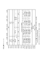
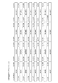
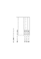
ここで、障害注入指示コマンドのフォーマットを図5に示す。例えば、障害注入指示コマンドのbit0からbit6には、障害タイプを指定するFTYPEが含まれる。bit7には、障害注入処理を実行するかどうかを指定するINJSTARTが含まれる。bit8からbit15には、障害注入モードを指定するFMODE(実施の形態2及び3で使用する)が含まれる。bit16からbit23には、障害注入対象のSCSI(Small・Computer・System・Interface)コマンドを指定するSCSICMDが含まれる。bit24からbit31には、障害注入スキップ頻度を指定するMDNUM(実施の形態3で使用する)が含まれる。bit32からbit63には、障害注入遅延時間を指定するMDTIME(実施の形態2で使用する)が含まれる。bit64からbit95には、応答遅延時間を指定するDLYTIMEが含まれる。bit96からbit127には、障害注入対象のFCポートIDを指定するFCPORTが含まれる。bit128からbit159には、障害注入対象のSCSIロジカルブロックアドレスを指定するSCSIADRが含まれる。
Here, the format of the fault injection instruction command is shown in FIG. For example,
障害シミュレータ11は、サーバA12からディスクA14に送信されるコマンドを検出し、必要な処理を行うことで「応答遅延」を実現することができる。FCではこのコマンドはFCP_CMNDと呼ばれるフレームである。
The
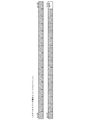
ここで、FCP_CMNDのフォーマットを図6に示す。FCP_CMNDは、word0:bit0からword16:bit31の順序で送信される。例えば、FCP_CMNDのword0には、フレームの先頭を示すSOFが含まれる。word1には、フレームの送信先ID(識別子)を示すD_ID、フレームの分類(機能)を示すR_CTLが含まれる。word2には、フレームの送信元IDを示すS_IDが含まれる。word3には、フレームのデータ部の分類を示すTYPEが含まれる。word10からword13には、フレームのデータ部が含まれる。word15には、誤り検出のためのCRC−32が含まれる。
Here, the format of FCP_CMND is shown in FIG. FCP_CMND is transmitted in the order of word0: bit0 to word16: bit31. For example,
以下では、障害注入指示コマンドが、ディスクA14の特定エリアからのリード処理が行われる際に障害を発生させるよう指示するものである場合について説明する。 Hereinafter, a case will be described in which the failure injection instruction command is an instruction to generate a failure when a read process from a specific area of the disk A14 is performed.
図4において、障害シミュレータ11は、サーバA12からディスクA14へ送信されるコマンド(フレーム)を解析する(ステップS103)。コマンドが、検証端末16により指定されたエリアからのリード処理を指示するFCP_CMNDであれば(ステップS104)、障害シミュレータ11は、そのFCP_CMNDを一定時間保持する(ステップS105)。これによって遅延を発生させた後、障害シミュレータ11は、保持していたFCP_CMNDをディスクA14へ送信する。ディスクA14は、FCP_CMNDを受け取ると応答を返す。
In FIG. 4, the
サーバA12からはFCP_CMNDに対する応答遅延が大きくなったように見える。ディスクA14からの応答遅延が、サーバA12のIO(Input/Output)タイムアウト値よりも大きくなった場合、サーバA12はディスクA14からのリード処理がタイムアウトになったと判定してIOタイムアウト処理を行う(ステップS106)。 From the server A12, it seems that the response delay to FCP_CMND is increased. When the response delay from the disk A14 becomes larger than the IO (Input / Output) timeout value of the server A12, the server A12 determines that the read processing from the disk A14 has timed out and performs the IO timeout process (step). S106).
二重系制御プログラムはサーバA12に障害があったと判定して、サーバB13に処理系を切り替える(ステップS107)。 The dual system control program determines that the server A12 has failed and switches the processing system to the server B13 (step S107).
以下では、障害シミュレータ11の詳細な動作について説明する。
Hereinafter, a detailed operation of the
障害シミュレータ11が動作する際には、前述したように、サーバA12において業務処理プログラムが実行され、業務処理が開始されている。このプログラムにはサーバA12からディスクA14へアクセスする処理が含まれている。
When the
検証端末16は、試験を行うためにサーバA12が業務処理を行っている状態で障害注入を指示する。ここでは、一例として、検証端末16が、以下のように設定された障害注入指示コマンドを障害シミュレータ11に送信することで、障害シミュレータ11に障害注入を指示するものとする。
(1)FTYPE(障害タイプ):「応答遅延」
(2)DLYTIME(応答遅延時間):1.5秒
(3)FCPORT(障害注入対象FCポートID):ディスクA14
(4)SCSICMD(障害注入対象SCSIコマンド):READ(リード処理)
(5)SCSIADR(障害注入対象SCSIロジカルブロックアドレス):1200_0000h
The
(1) FTYPE (failure type): “response delay”
(2) DLYTIME (response delay time): 1.5 seconds (3) FCPORT (failure injection target FC port ID): disk A14
(4) SCSICMD (failure injection target SCSI command): READ (read processing)
(5) SCSIIADR (failure injection target SCSI logical block address): 1200_0000h
「応答遅延」は、障害シミュレータ11がサーバA12から受信したFCP_CMNDを保存し、その内容が指定された条件に一致したらディスクA14への送信を一時停止し、その後指定された時間が経過すると、保存していたFCP_CMNDをディスクA14に送信することで実現する。FCでは、コンポーネント間の接続同期を維持するために、有意なデータを送信しないときはIDLEプリミティブ(データパターン:BC95_B5B5h)を送信しなくてはならない。したがって、ディスクA14へのFCP_CMNDの送信を一時停止している間、障害シミュレータ11はFCP_CMNDの代わりにIDLEプリミティブを送信しなくてはならない。また、検証端末16から障害注入処理開始の指示がなければ、障害シミュレータ11は特に多くのデータを保存する必要もなく、障害シミュレータ11の入出力遅延を短縮するために保存するデータ量を減らすことが望ましい。そこで、障害シミュレータ11では、制御部131がデータ選択部A152を制御して、ディスクA14へ送信するデータをデータ送信部A102に入力するための3つのデータ経路から1つを適宜選択する。3つのデータ経路とは、前述した第1データ経路173、第2データ経路174、第3データ経路175のことである。
“Response delay” stores the FCP_CMND received by the
第1データ経路173は、障害注入処理を開始していないときに選択されるデータ経路である。データ保存部A111は、データ受信部A101から入力された1回分のデータを保持する単データ保持部171と68バイトのFCP_CMNDを保存するための複データ保持部172を備えている。第1データ経路173は、単データ保持部171から複データ保持部172を経ずに(データ選択部A152を経て)データ送信部A102に直接つながるデータ経路である。第1データ経路173は、複データ保持部172をバイパスするため、このデータ経路を選択した場合には入出力遅延を短縮することができる。
The
第2データ経路174は、障害注入処理を開始したときに選択されるデータ経路である。第2データ経路174は、単データ保持部171から複データ保持部172(及びデータ選択部A152)を経てデータ送信部A102につながるデータ経路である。このデータ経路を選択した場合には、データ受信部A101から入力されるデータが全て単データ保持部171、複データ保持部172を経由してデータ送信部A102に入力される。
The second data path 174 is a data path selected when the fault injection process is started. The second data path 174 is a data path connected from the single
第3データ経路175は、複データ保持部172でのデータ保存開始の直後や、データ(FCP_CMNDである場合)送信の一時停止によりサーバA12からの受信データを利用できないときに選択されるデータ経路である。第3データ経路175は、代替送信データ出力部151から(データ選択部A152を経て)データ送信部A102につながるデータ経路である。このデータ経路を選択した場合には、サーバA12からの受信データの代わりに代替送信データ出力部151が出力するデータ(例えばIDLEプリミティブ)がデータ送信部A102に入力される。
The
FCでは、FCP_CMNDに対し、R_RDYプリミティブ(データパターン:BC95_4A4Ah)を返信して、FCP_CMNDを受信したことを送信元のコンポーネントに通知する必要がある。そのため、ディスクA14へのFCP_CMNDの送信を一時停止する場合、障害シミュレータ11はディスクA14の代わりにR_RDYプリミティブを返信する必要がある。また、その後でFCP_CMNDをディスクA14へ送信すると、ディスクA14からR_RDYプリミティブが返信されてくるため、これを破棄しなければならないが、このとき、障害シミュレータ11はR_RDYプリミティブの代わりにIDLEプリミティブを送信しなくてはならない。そこで、障害シミュレータ11では、制御部131がデータ選択部B153を制御して、サーバA12へ送信するデータをデータ送信部B103に入力するための2つのデータ経路から1つを適宜選択する。2つのデータ経路とは、前述した第4データ経路176、第5データ経路177のことである。
In FC, it is necessary to return an R_RDY primitive (data pattern: BC95_4A4Ah) to FCP_CMND to notify the transmission source component that FCP_CMND has been received. Therefore, when the transmission of FCP_CMND to the disk A14 is temporarily stopped, the
第4データ経路176は、障害注入処理を開始していないときや、障害注入処理を行っているときに選択されるデータ経路である。第4データ経路176は、データ保存部B112から(データ選択部B153を経て)データ送信部B103につながるデータ経路である。このデータ経路を選択した場合には、データ受信部B104から入力されるデータが全てデータ保存部B112を経由してデータ送信部B103に入力される。なお、このデータ経路を使わないのは、R_RDYプリミティブの破棄のときと、FCP_CMNDの受信通知のときだけである。
The
第5データ経路177は、R_RDYプリミティブの破棄、及び、FCP_CMNDの受信通知のとき、即ち、受信データを利用しないときに選択されるデータ経路である。第5データ経路177は、代替送信データ出力部151から(データ選択部B153を経て)データ送信部B103につながるデータ経路である。このデータ経路を選択した場合には、ディスクA14からの受信データの代わりに代替送信データ出力部151が出力するデータ(例えばIDLEプリミティブ、R_RDYプリミティブ)がデータ送信部B103に入力される。
The
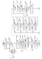
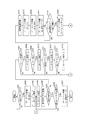
図7は、障害シミュレータ11の動作(本実施の形態に係る擬似障害発生方法、本実施の形態に係る擬似障害発生プログラムの処理手順)を示すフローチャートである。 FIG. 7 is a flowchart showing an operation of the failure simulator 11 (a simulated failure occurrence method according to the present embodiment, a processing procedure of the simulated failure occurrence program according to the present embodiment).
障害注入設定部182は、障害注入指示コマンドを検証端末I/F181を介して検証端末16から受信すると、記憶装置に保存する。制御部131は、記憶装置から直近の(即ち、障害注入設定部182が最後に受信した)障害注入指示コマンドを読み出し、障害注入指示コマンドのINJSTARTフィールドを処理装置により確認する(ステップS201)。INJSTARTフィールドが1になっていれば、制御部131は、障害注入処理を開始する。INJSTARTフィールドが0であれば、制御部131は、障害注入処理を開始せず、次の障害注入指示コマンドを待つ。
When the failure
制御部131は、ステップS201で障害注入処理を開始すると、データ選択部A152を制御し、第3データ経路175を選択する(ステップS202)。これにより、データ送信部A102は、再びデータ経路が切り替えられるまで、IDLEプリミティブをディスクA14に送信することになる。なお、障害注入処理の開始前、即ち、デフォルトでは、第1データ経路173が選択されているものとする。
When starting the fault injection process in step S201, the
データ受信部A101は、サーバA12から送信されたデータを受信する。データ受信部A101は、受信したデータのデシリアライズ及びデコードを行う。まず、データ受信部A101は、デコードを終えたデータをデータ保存部A111に2バイト送信する。データ保存部A111は、データ受信部A101から送られてきた2バイトのデータを単データ保持部171に一旦保存した後、複データ保持部172に保存する(ステップS203)。続けて、データ受信部A101は、デコードを終えたデータをデータ保存部A111に2バイトずつ送信する。データ保存部A111は、データ受信部A101から送られてきた2バイトのデータを複データ保持部172に保存する(ステップS204)。このとき、制御部131は、n=2とするnバイト保存処理を処理装置により実行する。
The data receiving unit A101 receives data transmitted from the server A12. The data receiving unit A101 performs deserialization and decoding of the received data. First, the data receiving unit A101 transmits 2 bytes of the decoded data to the data storage unit A111. The data storage unit A111 temporarily stores the 2-byte data transmitted from the data reception unit A101 in the single
図8に示すように、nバイト保存処理において、制御部131は、まず、受信データ数カウンタ192をクリアする(ステップS301)。即ち、受信データ数カウンタ192のカウンタ値を0にセットする。制御部131は、データ保存部A111に、データ受信部A101から送られてきた2バイトのデータを単データ保持部171に一旦保存させ、さらに、複データ保持部172に保存させる(ステップS302)。制御部131は、複データ保持部172に68バイトのデータが保存されているかどうかを判定する(ステップS303)。複データ保持部172に68バイトのデータが保存されていれば、複データ保持部172に有効なデータ、即ち、1フレーム分のデータが保存されたことになる。そのため、次サイクルからは、保存したデータのうち、後述するチェックが済んだデータをディスクA14へ送信することが可能になる。そこで、制御部131は、データ選択部A152を制御し、第2データ経路174を選択する(ステップS304)。これにより、データ送信部A102は、再びデータ経路が切り替えられるまで、データ選択部A152を介して複データ保持部172から入力されるデータをエンコード及びシリアライズしてディスクA14に送信することになる。なお、制御部131は、直近の障害注入指示コマンドのINJSTARTフィールドが0になっている場合にも、データ選択部A152を制御し、第2データ経路174を選択する。続けて、制御部131は、受信データ数カウンタ192を1つインクリメントする(ステップS305)。ステップS303で複データ保持部172に68バイトのデータが保存されていなければ、制御部131は、データ経路の変更はせずに、受信データ数カウンタ192を1つインクリメントする(ステップS305)。制御部131は、受信データ数カウンタ192のカウンタ値がn/2であるかどうかを判定する。カウンタ値がn/2でなければ、ステップS302から処理を繰り返す。カウンタ値がn/2であれば、nバイト保存処理を終了する。
As shown in FIG. 8, in the n-byte storage process, the
データ保存部A111は、ステップS204でn=2とするnバイト保存処理により、2バイトのデータを複データ保持部172に保存すると、直近の(即ち、最後に保存した)4バイトのデータをコマンド解析部141に出力する。コマンド解析部141は、データ保存部A111から受け取ったデータを解析し、そのデータがIDLEプリミティブであるかを処理装置により判定する。そして、コマンド解析部141は、判定結果を制御部131に通知する。制御部131は、判定結果に応じて、非IDLEフラグ191を更新する(ステップS205)。非IDLEフラグ191は、複データ保持部172に保存されているデータにIDLEプリミティブでないものが含まれているかどうかを示すフラグデータである。
When the data storage unit A111 stores the 2-byte data in the multiple
障害注入処理を終了するときには、データ経路をデフォルト設定の第1データ経路173に切り替える必要がある。そのための条件として、複データ保持部172に保存されているデータが全て破棄してよいデータ、即ち、IDLEプリミティブであることが必要である。これは、有効なデータを破棄しないためである。制御部131は、上記条件の判定のために非IDLEフラグ191を記憶装置に記憶している。複データ保持部172に保存されている最大で68バイトのデータの中に、コマンド解析部141がIDLEプリミティブであると判定したデータしか含まれていなければ、制御部131は、非IDLEフラグ191を無意に設定する。一方、1つでもコマンド解析部141がIDLEプリミティブでないと判定したデータが含まれていれば、制御部131は、非IDLEフラグ191を有意に設定する。
When ending the fault injection process, it is necessary to switch the data path to the default
制御部131は、記憶装置から直近の障害注入指示コマンドを読み出し、障害注入指示コマンドのINJSTARTフィールドを処理装置により確認する(ステップS206)。INJSTARTフィールドが0になっていれば、制御部131は、障害注入処理を終了する。INJSTARTフィールドが1であれば、制御部131は、障害注入処理を継続する。
The
コマンド解析部141は、ステップS206で制御部131が障害注入処理を継続する場合、ステップS205で解析した4バイトのデータがフレームの先頭であるかを処理装置により判定する(ステップS207)。具体的には、コマンド解析部141は、4バイトのデータがBCB5_5656hであれば、解析したデータがSOF、即ち、フレームの先頭であると判定する。コマンド解析部141が解析したデータがフレームの先頭である場合、制御部131は、n=4とするnバイト保存処理を処理装置により実行する(ステップS208)。ステップS207でコマンド解析部141が解析したデータがフレームの先頭でない場合、ステップS204に戻る。その後、次の2バイトが読み込まれ、ステップS207まで進んだ場合、コマンド解析部141は、その直前の2バイトと合わせた4バイトのデータを解析する。コマンド解析部141は、フレームの先頭を検出するまで同様の処理を繰り返す。
When the
データ保存部A111は、ステップS208でn=4とするnバイト保存処理により、後続の4バイトのデータを複データ保持部172に保存すると、その4バイトのデータをコマンド解析部141に出力する。コマンド解析部141は、データ保存部A111から受け取ったデータを解析し、末尾の1バイトのデータ、即ち、フレームの先頭から8バイト目のR_CTLフィールドがFCP_CMNDを示すものであるかを処理装置により判定する(ステップS209)。具体的には、コマンド解析部141は、R_CTLフィールドが06hであれば、受信中のフレームがFCP_CMNDであると判定する。フレームがFCP_CMNDである場合、制御部131は、n=36とするnバイト保存処理を処理装置により実行する(ステップS210)。ステップS209でフレームがFCP_CMNDでない場合、ステップS204に戻る。その後、次の2バイトが読み込まれ、ステップS207まで進んだ場合、コマンド解析部141は、その直前の2バイトと合わせた4バイトのデータを解析する。コマンド解析部141は、フレームの先頭を検出すると、R_CTLフィールドを解析する。コマンド解析部141は、FCP_CMNDを検出するまで同様の処理を繰り返す。
When the data storage unit A111 stores the subsequent 4-byte data in the multiple
データ保存部A111は、ステップS210でn=36とするnバイト保存処理により、後続の36バイトのデータを複データ保持部172に保存すると、その36バイトのデータをコマンド解析部141に出力する。コマンド解析部141は、データ保存部A111から受け取ったデータを解析し、末尾の1バイトのデータ、即ち、フレームの先頭から44バイト目のSCSI_CDB0フィールドがリード処理を示すものであるかを処理装置により判定する(ステップS211)。具体的には、コマンド解析部141は、SCSI_CDB0フィールドが28hであれば、受信中のFCP_CMNDがSCSIのREADコマンドであると判定する。FCP_CMNDがREADコマンドである場合、制御部131は、n=4とするnバイト保存処理を処理装置により実行する(ステップS212)。ステップS211でFCP_CMNDがREADコマンドでない場合、ステップS204に戻る。その後、次の2バイトが読み込まれ、ステップS207まで進んだ場合、コマンド解析部141は、その直前の2バイトと合わせた4バイトのデータを解析する。コマンド解析部141は、フレームの先頭を検出すると、R_CTLフィールドを解析する。コマンド解析部141は、FCP_CMNDを検出すると、SCSI_CDB0フィールドを解析する。コマンド解析部141は、READコマンドを検出するまで同様の処理を繰り返す。
When the data storage unit A111 stores the subsequent 36-byte data in the multiple
データ保存部A111は、ステップS212でn=4とするnバイト保存処理により、後続の4バイトのデータを複データ保持部172に保存すると、その4バイトのデータをコマンド解析部141に出力する。コマンド解析部141は、データ保存部A111から受け取ったデータを解析し、フレームの先頭から42バイト目のSCSI_CDB2フィールド、41バイト目のSCSI_CDB3フィールド、48バイト目のSCSI_CDB4フィールド、47バイト目のSCSI_CDB5フィールドの順番で4バイトのデータと、障害注入指示コマンドのSCSIADRフィールドの値とを処理装置により比較する(ステップS213)。ここで、SCSI_CDB2フィールド、SCSI_CDB3フィールド、SCSI_CDB4フィールド、SCSI_CDB5フィールドからなる4バイトのデータでは、FCP_CMNDがリード処理の対象として指定するSCSIロジカルブロックアドレスが示されているものとする。このSCSIロジカルブロックアドレスが障害注入指示コマンドのSCSIADRフィールドの値と一致する場合、障害を注入する条件が揃ったことになる。この場合、制御部131は、n=20とするnバイト保存処理を処理装置により実行する(ステップS214)。これにより、68バイトのFCP_CMNDの保存が完了したことになる。このとき、制御部131は、コマンド送信遅延タイマ161を開始する。ステップS213でFCP_CMNDがリード処理の対象として指定するSCSIロジカルブロックアドレスが障害注入指示コマンドのSCSIADRフィールドの値と一致しない場合、ステップS204に戻る。その後、次の2バイトが読み込まれ、ステップS207まで進んだ場合、コマンド解析部141は、その直前の2バイトと合わせた4バイトのデータを解析する。コマンド解析部141は、フレームの先頭を検出すると、R_CTLフィールドを解析する。コマンド解析部141は、FCP_CMNDを検出すると、SCSI_CDB0フィールドを解析する。コマンド解析部141は、READコマンドを検出すると、SCSI_CDB2フィールド、SCSI_CDB3フィールド、SCSI_CDB4フィールド、SCSI_CDB5フィールドを解析する。コマンド解析部141は、障害注入指示コマンドで指定されたSCSIロジカルブロックアドレスを処理対象とするREADコマンドを検出するまで同様の処理を繰り返す。
When the data storage unit A111 stores the subsequent 4-byte data in the multiple
制御部131は、ステップS214でデータ保存部A111が68バイトのFCP_CMNDを複データ保持部172に保存し終わると、データ保存部A111を制御し、これ以降、データ受信部A101から入力されるデータの保存を停止する。また、制御部131は、データ選択部A152を制御し、第3データ経路175を選択する(ステップS215)。これにより、データ送信部A102は、再びデータ経路が切り替えられるまで、IDLEプリミティブをディスクA14に送信することになる。
When the data storage unit A111 finishes storing the 68-byte FCP_CMND in the multiple
さらに、制御部131は、データ選択部B153を制御し、第5データ経路177を選択して、データ送信部B103にR_RDYプリミティブを送信させる(ステップS216)。これにより、障害シミュレータ11は、ディスクA14に代わってFCP_CMNDを受信したことをサーバA12に通知したことになる。なお、デフォルトでは、第4データ経路176が選択されているものとする。制御部131は、ステップS216でサーバA12にR_RDYプリミティブを送信すると、データ選択部B153を制御し、第4データ経路176を選択する(ステップS217)。これにより、データ送信部B103は、再びデータ経路が切り替えられるまで、ディスクA14からの受信データをサーバA12に送信することになる。
Further, the
制御部131は、コマンド送信遅延タイマ161のタイマ値と、障害注入指示コマンドのDLYTIMEフィールドの値とを処理装置により比較する(ステップS218)。具体的には、制御部131は、コマンド送信遅延タイマ161が1.5秒に達しているかどうかを判定する。コマンド送信遅延タイマ161のタイマ値と障害注入指示コマンドのDLYTIMEフィールドの値とが一致していなければ、一致するまで比較を続ける。ステップS218でコマンド送信遅延タイマ161のタイマ値と障害注入指示コマンドのDLYTIMEフィールドの値とが一致したら、FCP_CMNDをディスクA14に送信する条件が整ったことになる。そのため、制御部131は、データ選択部A152を制御し、第2データ経路174を選択して、データ選択部A152にFCP_CMNDを送信させる(ステップS219)。また、制御部131は、データ保存部A111を制御し、データ受信部A101から入力されるデータの保存を再開して、ステップS204に戻る。
The
上記のように、本実施の形態において、障害シミュレータ11のデータ受信部A101は、FC17でサーバA12からデータを受信する。障害シミュレータ11のデータ保存部A111は、データ受信部A101により受信されたデータを複データ保持部172に順次保存する。障害シミュレータ11のコマンド解析部141は、データ保存部A111により複データ保持部172に保存されている、最先のデータから1フレーム分のデータを処理装置により解析する。そして、コマンド解析部141は、解析した1フレーム分のデータがFCP_CMNDであるかどうかを処理装置により判定する。なお、本実施の形態では、所定のフレームの一例としてFCP_CMNDを用いているが、他の種類のフレームを用いてもよい。コマンド解析部141により解析された1フレーム分のデータがFCP_CMNDでないと判定された場合、障害シミュレータ11の制御部131は、複データ保持部172から最先のデータを取り出してデータ送信部A102に送信させる。障害シミュレータ11のデータ送信部A102は、FC18でディスクA14へデータを送信する。一方、コマンド解析部141により解析された1フレーム分のデータがFCP_CMNDであると判定された場合、制御部131は、擬似障害を処理装置により発生させる。この場合、具体的には、制御部131は、予め定められた時間(例えば、1.5秒)が経過するまで待機してから当該1フレーム分のデータをデータ送信部A102に送信させることで擬似障害を発生させる。
As described above, in the present embodiment, the data receiving unit A101 of the
コマンド解析部141は、解析した1フレーム分のデータがFCP_CMNDでなければ、再び、データ保存部A111により複データ保持部172に保存されている、最先のデータから1フレーム分のデータを処理装置により解析する。なお、このときの最先のデータは、制御部131により最先のデータ(コマンド解析部141が前回解析したデータ)が取り出されたことにより新たに最先のデータとなったデータである。コマンド解析部141は、前回と同様に、解析した1フレーム分のデータがFCP_CMNDであるかどうかを処理装置により判定する。制御部131は、コマンド解析部141の判定結果に応じて、前回と同様に処理を行う。以降、同様の処理が繰り返される。つまり、制御部131は、コマンド解析部141による判定の結果が出る度に、当該結果に応じて動作する。
If the analyzed data for one frame is not FCP_CMND, the
障害シミュレータ11の代替送信データ出力部151は、IDLEプリミティブを処理装置により生成する。なお、本実施の形態では、データ保存部A111により保存されたデータの代わりとなるデータの一例としてIDLEプリミティブを用いているが、他の種類のデータを用いてもよい。制御部131は、データ保存部A111により複データ保持部172に保存されているデータが1フレーム分に満たない場合、代替送信データ出力部151により生成されたIDLEプリミティブをデータ送信部A102に送信させる。データ送信部A102は、FC18でディスクA14へIDLEプリミティブを送信する。
The alternative transmission
なお、本実施の形態では、データ保存部A111、制御部131、コマンド解析部141等は、データを2バイトずつ処理しているが、任意のバイト数を単位として処理を行ってよい。例えば、データを1バイトずつ処理してもよいし、4バイトずつ処理してもよい。
In the present embodiment, the data storage unit A111, the
以上説明した障害シミュレータ11の処理により、ディスクA14は、障害注入指示コマンドのDLYTIMEフィールドで指定された時間(具体的には、1.5秒)が経過した後にFCP_CMND(具体的には、READコマンド)を受信することになる。ディスクA14は、障害シミュレータ11からFCP_CMNDを受信すると、FCP_CMNDを受信したことを通知するためにR_RDYプリミティブをサーバA12宛てに送信する。その後、ディスクA14は、リードデータが準備できると、リードデータをサーバA12宛てに送信する。また、ディスクA14は、リードデータの送信が完了すると、リード時のエラーの有無等を示すステータス情報をサーバA12宛てに送信する。
As a result of the processing of the
障害シミュレータ11は、ディスクA14から送信されたデータをデータ受信部B104で受信する。データ受信部B104は、受信したデータのデシリアライズ及びデコードを行う。データ受信部B104は、デコードを終えたデータをデータ保存部B112に2バイトずつ送信する。データ保存部B112は、データ受信部B104から送られてきたデータを保存するとともに、直近の(即ち、最後に保存した)4バイトのデータをデータ解析部142に出力する。
The
データ解析部142は、入力された4バイトのデータを解析し、そのデータがR_RDYプリミティブであるかを処理装置により判定する。そして、データ解析部142は、判定結果を制御部131に通知する。具体的には、データ解析部142は、データ保存部B112から受け取った4バイトのデータがBC95_4A4Ahであれば、そのデータがR_RDYプリミティブであると判定して制御部131に通知する。制御部131は、データ選択部B153及び代替送信データ出力部151を制御し、第5データ経路177を選択して、ディスクA14から受信したR_RDYプリミティブの代わりにIDLEプリミティブをデータ送信部B103に出力する。これにより、ディスクA14から受信したR_RDYプリミティブを破棄する。これは、前述したように、障害シミュレータ11がFCP_CMNDを受信したことを通知するためのR_RDYプリミティブを既に送信しており、R_RDYプリミティブを二重に送信するのを避けるためである。制御部131は、IDLEプリミティブを送信すると、データ選択部B153を制御し、データ経路を第4データ経路176に戻す。これにより、データ送信部B103は、再びデータ経路が切り替えられるまで、ディスクA14からの受信データをサーバA12に送信することになる。
The
上記のように、本実施の形態において、障害シミュレータ11のデータ受信部B104は、FCP_CMNDに対してディスクA14から返信されるフレームを受信する。障害シミュレータ11のデータ保存部B112は、データ受信部B104により受信されたデータを一時的に保存する。障害シミュレータ11のデータ送信部B103は、データ保存部B112により保存されたデータをサーバA12へ送信(転送)する。
As described above, in the present embodiment, the data receiving unit B104 of the
サーバA12は、自身が発行したSCSIのREADコマンドに対する応答(リードデータ)を待つ。障害シミュレータ11によりディスクA14がコマンドを受信するのが、障害注入指示コマンドのDLYTIMEフィールドで指定された時間(具体的には、1.5秒)遅れるため、その分リードデータがディスクA14から送信されるタイミングも遅れる。したがって、サーバA12では、見かけ上リードデータが到達するのが1.5秒遅れた形になる。この遅延時間がサーバA12のIOタイムアウト値より大きいとIOタイムアウトとしてサーバA12は異常時処理を行う。異常時処理では、二重系制御プログラムが、サーバA12に異常があったことを検知し、系の切り替えを実行する。また、系切り替えの要因と時刻をログに記録し、IOタイムアウトが発生したことがわかるようにする。サーバB13は、二重系制御プログラムによる系切り替えにより業務処理を開始する。また、サーバB13は、業務処理の開始時刻をログに記録する。一方、上記遅延時間がサーバA12のIOタイムアウト値より小さいとIOタイムアウトは発生しない。そのため、サーバAは業務処理を続けることになる。
The server A12 waits for a response (read data) to the SCSI READ command issued by itself. Since the
検証端末16は、サーバA12及びサーバB13からログを収集する。検証端末16は、定期的にログを確認することで系切り替え処理の有無等を確認する。検証端末16は、例えば、系切り替え処理が実行されたことを確認すると、INJSTARTフィールドを0に設定した障害注入指示コマンドを障害シミュレータ11に送信することで、障害シミュレータ11に障害注入の停止を指示する。
The
前述したように、障害注入設定部182は、障害注入指示コマンドを検証端末I/F181を介して検証端末16から受信すると、記憶装置に保存する。ステップS206において、制御部131は、記憶装置から直近の(即ち、障害注入設定部182が最後に受信した)障害注入指示コマンドを読み出し、障害注入指示コマンドのINJSTARTフィールドを処理装置により確認する。INJSTARTフィールドが0になっていれば、制御部131は、障害注入処理を終了する。INJSTARTフィールドが1であれば、制御部131は、障害注入処理を継続する。
As described above, when the failure
制御部131は、ステップS206で障害注入処理を終了する場合、非IDLEフラグ191を処理装置により確認する(ステップS220)。非IDLEフラグ191が有意であれば、ステップS204に戻り、非IDLEフラグ191が無意になるまでステップS220までの動作を繰り返す。なお、ステップS204では、直近の障害注入指示コマンドのINJSTARTフィールドが0になっているため、必ず第2データ経路174が選択される。これにより、データ送信部A102は、複データ保持部172に保存されているデータをディスクA14に順次送信することになる。また、FCP_CMNDが受信されても、直近の障害注入指示コマンドのINJSTARTフィールドが0になっているため、ステップS207以降の処理において制御部131が「応答遅延」を発生させることはない。制御部131は、ステップS220で非IDLEフラグ191が無意になると、データ選択部A152を制御し、データ経路を通常の第1データ経路173に戻す(ステップS221)。これにより、データ送信部A102は、再びデータ経路が切り替えられるまで、サーバA12からの受信データをディスクA14に送信することになる。
When ending the fault injection process in step S206, the
以上説明したように、本実施の形態では、障害シミュレータ11が、コマンド解析部141と、コマンド解析部141の判定結果に応じて制御を行う制御部131を備えることにより、2つの装置間で送受信されるデータの内容に応じて擬似的に障害を発生させることができる。例えば、サーバA12から送信される特定のコマンドやディスクA14内の特定のエリアに対するアクセスを対象に障害注入を行うことが可能である。このため、障害注入の対象を限定することができ、二重系システム等の品質を高めるためにきめ細やかな試験を行うことが可能となる。
As described above, in the present embodiment, the
以上、障害注入指示コマンドが、ディスクA14の特定エリアからのリード処理が行われる際に障害を発生させるよう指示するものである場合について説明したが、障害注入指示コマンドが、ディスクA14の特定エリアへのライト処理が行われる際に障害を発生させるよう指示するものである場合についても上記と同様である。例えば、サーバA12がコマンドを発行後に待つのがリードデータではなくREADYになり、また、その後にサーバA12からライトデータが送信されるといった違いはあるが、障害注入処理に関しては同様の動作となる。 The case where the failure injection instruction command instructs to generate a failure when a read process is performed from a specific area of the disk A14 has been described. However, the failure injection instruction command is directed to a specific area of the disk A14. The same applies to the case where an instruction is given to generate a failure when the write process is performed. For example, although the server A12 waits after issuing a command is READY instead of read data, and write data is transmitted from the server A12 thereafter, the same operation is performed with respect to the fault injection processing.
以下では、特定のコマンドを対象にして擬似的な障害を発生させる方法について、障害タイプ「無応答」を例に説明する。なお、以下では、障害注入指示コマンドが、ディスクA14の特定エリアからのリード処理が行われる際に障害を発生させるよう指示するものである場合について説明するが、障害注入指示コマンドが、ディスクA14の特定エリアへのライト処理が行われる際に障害を発生させるよう指示するものである場合についても同様である。 In the following, a method for generating a pseudo failure for a specific command will be described by taking the failure type “no response” as an example. In the following description, a case where the failure injection instruction command instructs to generate a failure when a read process from a specific area of the disk A14 is performed will be described. The same applies to a case in which a failure is instructed when a write process to a specific area is performed.
図9は、障害シミュレータ11の動作(本実施の形態に係る擬似障害発生方法、本実施の形態に係る擬似障害発生プログラムの処理手順)を示すフローチャートである。 FIG. 9 is a flowchart showing an operation of the failure simulator 11 (a simulated failure occurrence method according to the present embodiment, a processing procedure of the simulated failure occurrence program according to the present embodiment).
図9において、ステップS201〜S217、S220、S221の処理は、前述した障害タイプ「応答遅延」の例と同様である。 In FIG. 9, the processes in steps S201 to S217, S220, and S221 are the same as the example of the failure type “response delay” described above.
この例では、ステップS217の後、ステップS204に戻る。これにより、サーバA12が発行したコマンドは、ディスクA14に送信されることなく破棄されたことになる。ディスクA14はコマンドを受信しないため、サーバA12には応答(リードデータ)を送信しない。したがって、サーバA12では、見かけ上ディスクA14からコマンドに対する応答が得られない形になる。このため、サーバA12は異常時処理を行う。異常時処理では、前述したように、二重系制御プログラムが、サーバA12に異常があったことを検知し、系の切り替えを実行する。 In this example, after step S217, the process returns to step S204. As a result, the command issued by the server A12 is discarded without being transmitted to the disk A14. Since the disk A14 does not receive the command, no response (read data) is transmitted to the server A12. Therefore, the server A12 apparently cannot obtain a response to the command from the disk A14. For this reason, the server A12 performs an abnormality process. In the process at the time of abnormality, as described above, the dual system control program detects that there is an abnormality in the server A12 and executes system switching.
以下では、特定のコマンドを対象にして擬似的な障害を発生させる方法について、障害タイプ「リンク断」を例に説明する。なお、以下では、障害注入指示コマンドが、ディスクA14の特定エリアからのリード処理が行われる際に障害を発生させるよう指示するものである場合について説明するが、障害注入指示コマンドが、ディスクA14の特定エリアへのライト処理が行われる際に障害を発生させるよう指示するものである場合についても同様である。 In the following, a method of generating a pseudo failure for a specific command will be described by taking the failure type “link break” as an example. In the following description, a case where the failure injection instruction command instructs to generate a failure when a read process from a specific area of the disk A14 is performed will be described. The same applies to a case in which a failure is instructed when a write process to a specific area is performed.
図10は、障害シミュレータ11の動作(本実施の形態に係る擬似障害発生方法、本実施の形態に係る擬似障害発生プログラムの処理手順)を示すフローチャートである。 FIG. 10 is a flowchart showing an operation of the failure simulator 11 (a simulated failure occurrence method according to the present embodiment, a processing procedure of the simulated failure occurrence program according to the present embodiment).
図10において、ステップS201〜S214、S220、S221の処理は、前述した障害タイプ「応答遅延」の例と同様である。 In FIG. 10, the processes in steps S201 to S214, S220, and S221 are the same as the example of the failure type “response delay” described above.
この例では、ステップS214の後、制御部131は、データ送信部A102及びデータ送信部B103を制御し、電気的アイドルな状態(例えばバッファ電源OFF)に移る(ステップS231)。これにより、サーバA12とディスクA14の接続同期がとれなくなり、リンク断の状態になる。このため、サーバA12は異常時処理を行う。異常時処理では、前述したように、二重系制御プログラムが、サーバA12に異常があったことを検知し、系の切り替えを実行する。
In this example, after step S214, the
上記のように、本実施の形態において、コマンド解析部141により解析された1フレーム分のデータがFCP_CMNDであると判定された場合、制御部131は、当該1フレーム分のデータをデータ送信部A102に送信させないことで擬似障害を発生させることもできる。
As described above, in the present embodiment, when it is determined that the data for one frame analyzed by the
以下では、特定のコマンドを対象にして擬似的な障害を発生させる方法について、障害タイプ「応答異常」を例に説明する。なお、以下では、障害注入指示コマンドが、ディスクA14の特定エリアからのリード処理が行われる際に障害を発生させるよう指示するものである場合について説明するが、障害注入指示コマンドが、ディスクA14の特定エリアへのライト処理が行われる際に障害を発生させるよう指示するものである場合についても同様である。 In the following, a method for generating a pseudo failure for a specific command will be described by taking the failure type “response abnormality” as an example. In the following description, a case where the failure injection instruction command instructs to generate a failure when a read process from a specific area of the disk A14 is performed will be described. The same applies to a case in which a failure is instructed when a write process to a specific area is performed.
図11及び図12は、障害シミュレータ11の動作(本実施の形態に係る擬似障害発生方法、本実施の形態に係る擬似障害発生プログラムの処理手順)を示すフローチャートである。 FIGS. 11 and 12 are flowcharts showing the operation of the failure simulator 11 (a simulated fault occurrence method according to the present embodiment, a processing procedure of the simulated fault occurrence program according to the present embodiment).
図11において、ステップS201〜S208、S220、S221の処理は、前述した障害タイプ「応答遅延」の例と同様である。 In FIG. 11, the processes in steps S201 to S208, S220, and S221 are the same as the example of the failure type “response delay” described above.
制御部131は、ステップS208でn=4とするnバイト保存処理により、データ保存部A111が4バイトのデータを複データ保持部172に保存すると、その4バイトのデータの先頭から3バイトのデータ、即ち、D_IDフィールドのデータをD_ID保存部193に保存させる(ステップS241)。ここで、D_IDフィールドでは、ディスクA14のポートIDが示されているものとする。この後、ステップS209〜S213の処理が実行される。ステップS209〜S213の処理は、前述した障害タイプ「応答遅延」の例と同様である。
When the data storage unit A111 stores the 4-byte data in the multiple
ステップS213でFCP_CMNDがリード処理の対象として指定するSCSIロジカルブロックアドレスが障害注入指示コマンドのSCSIADRフィールドの値と一致する場合、障害を注入する条件が揃ったことになる。この場合、コマンド解析部141は、制御部131にCRCエラーを発生させる条件が整ったことを通知する。制御部131は、CRCエラー注入処理を起動し、データ解析部142を制御してデータ保存部B112のデータ解析を開始させる(ステップS242)。この後、ステップS214の処理が実行される。ステップS214の処理は、前述した障害タイプ「応答遅延」の例と同様である。ステップS214の後は、ステップS204に戻る。
If the SCSI logical block address specified by FCP_CMND as the target of the read process in step S213 matches the value of the SCSIADR field of the failure injection instruction command, the conditions for injecting the failure are ready. In this case, the
以上説明した障害シミュレータ11の処理により、ディスクA14は、通常のFCP_CMND(具体的には、READコマンド)を受信することになる。ディスクA14は、障害シミュレータ11からFCP_CMNDを受信すると、FCP_CMNDを受信したことを通知するためにR_RDYプリミティブをサーバA12宛てに送信する。その後、ディスクA14は、リードデータが準備できると、リードデータをサーバA12宛てに送信する。また、ディスクA14は、リードデータの送信が完了すると、リード時のエラーの有無等を示すステータス情報をサーバA12宛てに送信する。
By the processing of the
図12において、障害シミュレータ11は、ディスクA14から送信されたデータをデータ受信部B104で受信する。データ受信部B104は、受信したデータのデシリアライズ及びデコードを行う。データ受信部B104は、デコードを終えたデータをデータ保存部B112に2バイトずつ送信する(ステップS401)。データ保存部B112は、データ受信部B104から送られてきたデータを保存するとともに、直近の(即ち、最後に保存した)4バイトのデータをデータ解析部142に出力する。
In FIG. 12, the
データ解析部142は、入力された4バイトのデータを解析し、そのデータがフレームの先頭であるかを処理装置により判定する(ステップS402)。具体的には、データ解析部142は、4バイトのデータがBCB5_5656hであれば、解析したデータがSOF、即ち、フレームの先頭であると判定する。データ解析部142は、解析したデータがフレームの先頭である場合、後続のデータを解析し、フレームの先頭から9〜11バイト目のS_IDフィールドのデータと、D_ID保存部193に保存されたデータとを処理装置により比較する(ステップS403)。一方、ステップS402でデータ解析部142が解析したデータがフレームの先頭でない場合、ステップS401に戻る。その後、次の2バイトが読み込まれ、ステップS402で、データ解析部142は、その直前の2バイトと合わせた4バイトのデータを解析する。データ解析部142は、フレームの先頭を検出するまで同様の処理を繰り返す。
The
S_IDフィールドでは、送信元コンポーネントのポートIDが示されている。そのため、制御部131は、ステップS403でS_IDフィールドのデータとD_ID保存部193に保存されたデータが一致すれば、データ解析部142により解析されたフレームがディスクA14から受信したものであると処理装置により判定する。そして、制御部131は、データ置換部154を制御し、受信したフレームのデータを加工する(ステップS404)。例えば、データ置換部154は、データを加工しないで送り出す経路と、データを反転する経路を選択的に使用するものであり、制御部131からどちらの経路を使用させるか制御できるものとする。ここでは、一例として、加工対象とするデータをS_IDフィールドのデータとする。制御部131は、S_IDフィールドのデータのみについて、データを反転する経路を使用するようにデータ置換部154を制御する。データ置換部154は、データをデータ選択部B153に出力する。データ送信部B103は、データ選択部B153を介して入力されるデータをエンコード及びシリアライズしてサーバA4に送信する(ステップS405)。
In the S_ID field, the port ID of the transmission source component is indicated. Therefore, if the data in the S_ID field matches the data stored in the
サーバA12は、自身が発行したSCSIのREADコマンドに対する応答(リードデータ)を待つ。障害シミュレータ11によりリードデータがCRCエラーを含むフレームに加工されているため、サーバA12は異常時処理を行う。異常時処理では、前述したように、二重系制御プログラムが、サーバA12に異常があったことを検知し、系の切り替えを実行してもよいし、他の処理が行われてもよい。
The server A12 waits for a response (read data) to the SCSI READ command issued by itself. Since the read data is processed into a frame including a CRC error by the
上記のように、本実施の形態において、コマンド解析部141により解析された1フレーム分のデータがFCP_CMNDであると判定された場合、制御部131は、当該1フレーム分のデータをデータ送信部A102に送信させる。そして、制御部131は、当該1フレーム分のデータに対してディスクA14から返信されるフレームをデータ送信部B103に転送させる際に、当該フレームの一部のデータを変更することで擬似障害を発生させることもできる。
As described above, in the present embodiment, when it is determined that the data for one frame analyzed by the
実施の形態2.
本実施の形態について、主に実施の形態1との差異を説明する。
In the present embodiment, differences from the first embodiment will be mainly described.
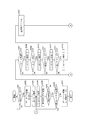
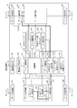
図13は、本実施の形態に係る障害シミュレータ11の構成を示すブロック図である。
FIG. 13 is a block diagram illustrating a configuration of the
図13において、障害シミュレータ11は、実施の形態1と同様の構成要素に加えて、障害注入遅延タイマ162を備える。
In FIG. 13, the
実施の形態1において、業務処理プログラムを実行してからすぐに障害注入を開始すると、試験をしたいタイミングと違うタイミングで障害が注入されてしまう可能性がある。例えば、試験対象は業務プログラム内の定常処理であるが、業務処理プログラム内の初期化処理において障害注入対象となるコマンドが発行されるとその時点で障害が注入されてしまう。本実施の形態では、このようなことを防ぐために、障害シミュレータ11が障害注入を開始するタイミングを調整する機能(障害注入遅延モード)を有する。
In the first embodiment, if the fault injection is started immediately after the execution of the business process program, there is a possibility that the fault is injected at a timing different from the timing at which the test is desired. For example, the test target is a steady process in a business program, but when a command that is a target for fault injection is issued in the initialization process in the business process program, a fault is injected at that time. In the present embodiment, in order to prevent such a situation, the
以下では、試験システム10の動作について、障害タイプ「応答遅延」を例に説明するが、障害タイプが「無応答」、「リンク断」、「応答異常」であっても同様の動作が可能である。また、以下では、障害注入指示コマンドが、ディスクA14の特定エリアからのリード処理が行われる際に障害を発生させるよう指示するものである場合について説明するが、障害注入指示コマンドが、ディスクA14の特定エリアへのライト処理が行われる際に障害を発生させるよう指示するものである場合についても同様である。 In the following, the operation of the test system 10 will be described using the failure type “response delay” as an example, but the same operation is possible even if the failure type is “no response”, “link disconnection”, or “response abnormality”. is there. In the following, a case will be described in which the failure injection instruction command instructs to generate a failure when a read process from a specific area of the disk A14 is performed. The same applies to a case in which a failure is instructed when a write process to a specific area is performed.
検証端末16は、実施の形態1と同様に、試験を行うためにサーバA12が業務処理を行っている状態で障害注入を指示する。ここでは、一例として、検証端末16が、以下のように設定された障害注入指示コマンドを障害シミュレータ11に送信することで、障害シミュレータ11に障害注入を指示するものとする。
(1)FTYPE(障害タイプ):「応答遅延」
(2)DLYTIME(応答遅延時間):1.5秒
(3)FCPORT(障害注入対象FCポートID):ディスクA14
(4)SCSICMD(障害注入対象SCSIコマンド):READ(リード処理)
(5)SCSIADR(障害注入対象SCSIロジカルブロックアドレス):1200_0000h
(6)FMODE(障害注入モード):2(障害注入遅延モード)
(7)MDTIME(障害注入遅延時間):2.5秒
As in the first embodiment, the
(1) FTYPE (failure type): “response delay”
(2) DLYTIME (response delay time): 1.5 seconds (3) FCPORT (failure injection target FC port ID): disk A14
(4) SCSICMD (failure injection target SCSI command): READ (read processing)
(5) SCSIIADR (failure injection target SCSI logical block address): 1200_0000h
(6) FMODE (failure injection mode): 2 (failure injection delay mode)
(7) MDTIME (failure injection delay time): 2.5 seconds
障害シミュレータ11は、障害注入指示コマンドのFMODEフィールドに2が指定された場合には、障害注入指示コマンドを受け付けてもすぐに障害注入処理を開始しない。障害シミュレータ11は、障害注入遅延タイマ162で計時し、障害注入指示コマンドのMDTIMEフィールドで指定された時間が経過してから障害注入処理を開始する。なお、障害を注入する方法については実施の形態1と同様である。
If 2 is specified in the FMODE field of the fault injection instruction command, the
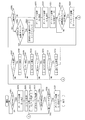
図14は、障害シミュレータ11の動作(本実施の形態に係る擬似障害発生方法、本実施の形態に係る擬似障害発生プログラムの処理手順)を示すフローチャートである。 FIG. 14 is a flowchart showing an operation of the failure simulator 11 (a simulated failure occurrence method according to the present embodiment, a processing procedure of the simulated failure occurrence program according to the present embodiment).
実施の形態1と同様に、障害注入設定部182は、障害注入指示コマンドを検証端末I/F181を介して検証端末16から受信すると、記憶装置に保存する。制御部131は、記憶装置から直近の(即ち、障害注入設定部182が最後に受信した)障害注入指示コマンドを読み出し、障害注入指示コマンドのINJSTARTフィールドを処理装置により確認する(ステップS201)。INJSTARTフィールドが0であれば、制御部131は、障害注入処理を開始せず、次の障害注入指示コマンドを待つ。
As in the first embodiment, when the failure
制御部131は、ステップS201でINJSTARTフィールドが1であれば、障害注入指示コマンドのFMODEフィールドを処理装置により確認する(ステップS251)。FMODEフィールドが2でなければ、制御部131は、障害注入処理を開始する。この後、ステップS202〜S221の処理が実行される。ステップS202〜S221の処理は、実施の形態1と同様である。
If the INJSTART field is 1 in step S201, the
制御部131は、ステップS202でFMODEフィールドが2であれば、障害遅延注入モードが指定されていると処理装置により判定する。この場合、制御部131は、すぐに障害注入処理を開始せず、障害注入遅延タイマ162により障害注入処理の開始のタイミングを制御する。具体的には、制御部131は、まず、障害注入遅延タイマ162を起動させる。そして、制御部131は、障害注入遅延タイマ162のタイマ値と、障害注入指示コマンドのMDTIMEフィールドの値(具体的には、2.5秒)とを処理装置により比較する。両者が一致しなければ、一致するまで制御部131は比較を続ける。両者が一致すれば、制御部131は、障害注入処理を開始する。この後、ステップS202〜S221の処理が実行される。ステップS202〜S221の処理は、実施の形態1と同様である。
If the FMODE field is 2 in step S202, the
上記のように、本実施の形態において、検証端末16は、障害シミュレータ11に対して時間を指定する信号を入力する。障害シミュレータ11の制御部131は、検証端末16からの信号で指定された時間が経過するまで待機してから動作し始める。
As described above, in the present embodiment, the
以上説明したように、本実施の形態では、障害シミュレータ11が、障害注入指示コマンドのMDTIMEフィールドで指定された時間を経過してから障害注入処理を開始する機能を有する。この機能を使うことで障害注入処理の開始タイミングを制御することができるようになる。これにより、試験をしたいタイミングと違うタイミングで障害が注入されてしまう事態を回避することができる。
As described above, in the present embodiment, the
実施の形態3.
本実施の形態について、主に実施の形態1との差異を説明する。
In the present embodiment, differences from the first embodiment will be mainly described.
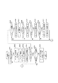
図15は、本実施の形態に係る障害シミュレータ11の構成を示すブロック図である。
FIG. 15 is a block diagram showing a configuration of the
図15において、障害シミュレータ11は、実施の形態1と同様の構成要素に加えて、障害注入回数カウンタ163を備える。
15, the
実施の形態1において、サーバA12に、IOタイムアウト等の障害が発生してもリトライをして救済するようなシステムを採用することができる。このようなシステムでは、規定のリトライ回数まではリトライを繰り返すが、規定値を超えるとリトライをやめて、異常処理を行う。本実施の形態では、このような規定値に関する試験を可能にするため、障害シミュレータ11が障害注入を一旦停止する機能(障害間欠注入モード)を有する。
In the first embodiment, it is possible to adopt a system in which a retry is made and rescued even if a failure such as an IO timeout occurs in the server A12. In such a system, the retry is repeated up to a specified number of retries, but when the specified value is exceeded, the retry is stopped and an abnormal process is performed. In the present embodiment, the
以下では、試験システム10の動作について、障害タイプ「応答遅延」を例に説明するが、障害タイプが「無応答」、「リンク断」、「応答異常」であっても同様の動作が可能である。また、以下では、障害注入指示コマンドが、ディスクA14の特定エリアからのリード処理が行われる際に障害を発生させるよう指示するものである場合について説明するが、障害注入指示コマンドが、ディスクA14の特定エリアへのライト処理が行われる際に障害を発生させるよう指示するものである場合についても同様である。 In the following, the operation of the test system 10 will be described using the failure type “response delay” as an example, but the same operation is possible even if the failure type is “no response”, “link disconnection”, or “response abnormality”. is there. In the following, a case will be described in which the failure injection instruction command instructs to generate a failure when a read process from a specific area of the disk A14 is performed. The same applies to a case in which a failure is instructed when a write process to a specific area is performed.
検証端末16は、実施の形態1と同様に、試験を行うためにサーバA12が業務処理を行っている状態で障害注入を指示する。ここでは、一例として、検証端末16が、以下のように設定された障害注入指示コマンドを障害シミュレータ11に送信することで、障害シミュレータ11に障害注入を指示するものとする。
(1)FTYPE(障害タイプ):「応答遅延」
(2)DLYTIME(応答遅延時間):1.5秒
(3)FCPORT(障害注入対象FCポートID):ディスクA14
(4)SCSICMD(障害注入対象SCSIコマンド):READ(リード処理)
(5)SCSIADR(障害注入対象SCSIロジカルブロックアドレス):1200_0000h
(6)FMODE(障害注入モード):3(障害間欠注入モード)
(7)MDNUM(障害注入スキップ頻度):4回(4回に1回)
As in the first embodiment, the
(1) FTYPE (failure type): “response delay”
(2) DLYTIME (response delay time): 1.5 seconds (3) FCPORT (failure injection target FC port ID): disk A14
(4) SCSICMD (failure injection target SCSI command): READ (read processing)
(5) SCSIIADR (failure injection target SCSI logical block address): 1200_0000h
(6) FMODE (failure injection mode): 3 (failure intermittent injection mode)
(7) MDNUM (Frequency injection skip frequency): 4 times (once every 4 times)
障害シミュレータ11は、障害注入指示コマンドのFMODEフィールドに3が指定された場合には、障害注入指示コマンドを受け付けるとすぐに障害注入処理を開始するが、障害注入指示コマンドのMDNUMフィールドで指定された回数に1回は障害を注入せずに受信データをそのままディスクA14に送信する。なお、障害を注入する方法については実施の形態1と同様である。
When 3 is specified in the FMODE field of the failure injection instruction command, the
図16は、障害シミュレータ11の動作(本実施の形態に係る擬似障害発生方法、本実施の形態に係る擬似障害発生プログラムの処理手順)を示すフローチャートである。 FIG. 16 is a flowchart showing an operation of the failure simulator 11 (a simulated failure occurrence method according to the present embodiment, a processing procedure of the simulated failure occurrence program according to the present embodiment).
図16において、ステップS201〜S214、S220、S221の処理は、実施の形態1と同様である。 In FIG. 16, the processes in steps S201 to S214, S220, and S221 are the same as those in the first embodiment.
制御部131は、ステップS214でデータ保存部A111が68バイトのFCP_CMNDを複データ保持部172に保存し終わると、記憶装置から直近の(即ち、障害注入設定部182が最後に受信した)障害注入指示コマンドを読み出し、障害注入指示コマンドのFMODEフィールドを処理装置により確認する(ステップS261)。FMODEフィールドが3でなければ、ステップS215〜S219の処理が実行される。ステップS215〜S219の処理は、実施の形態1と同様である。
When the data storage unit A111 finishes storing the 68-byte FCP_CMND in the multiple
制御部131は、ステップS261でFMODEフィールドが3であれば、障害間欠注入モードが指定されていると処理装置により判定する。この場合、制御部131は、障害注入回数カウンタ163のカウンタ値(初期値は0とする)と、障害注入指示コマンドのMDNUMフィールドの値から1を減じた値(具体的には、3)とを処理装置により比較する(ステップS262)。両者が一致すれば、制御部131は、障害注入回数カウンタ163をリセットしてカウンタ値を0に戻した上で、障害注入をスキップしてFCP_CMNDを遅延させずにデータ送信部AによりディスクA14へ送信する。一方、両者が一致しなければ、制御部131は、障害注入回数カウンタ163を1つインクリメントする(ステップS263)。この後、ステップS215〜S219の処理が実行される。ステップS215〜S219の処理は、実施の形態1と同様である。
If the FMODE field is 3 in step S261, the
上記のように、本実施の形態において、検証端末16は、障害シミュレータ11に対して頻度を指定する信号を入力する。障害シミュレータ11の制御部131は、コマンド解析部141により解析された1フレーム分のデータがFCP_CMNDであると判定された場合、毎回擬似障害を発生させる代わりに検証端末16からの信号で指定された頻度で擬似障害を発生させる。
As described above, in the present embodiment, the
以上説明したように、本実施の形態では、障害シミュレータ11が、障害が発生してもリトライを行い救済するようなシステムにおいて、障害注入指示コマンドのMDNUMフィールドで指定された回数に1回は障害を注入しない機能を有する。この機能を使うことで、間欠障害を擬似的に発生させることができ、システムにおいてリトライによる救済が行えているかどうか等を確認することが可能になる。
As described above, in the present embodiment, in the system in which the
なお、本実施の形態では、障害シミュレータ11が、障害注入指示コマンドのMDNUMフィールドで指定された回数につき1回だけ障害注入をスキップするが、当該回数につき複数回障害注入をスキップするようにしてもよい。例えば、障害注入回数カウンタ163のカウンタ値が、障害注入指示コマンドのMDNUMフィールドの値から1を減じた値(具体的には、3)と一致した場合だけでなく、MDNUMフィールドの値から2を減じた値(具体的には、2)と一致した場合にも、障害シミュレータ11が障害注入をスキップするようにしてもよい。ただし、障害注入回数カウンタ163をリセットするのは、障害注入回数カウンタ163のカウンタ値が、障害注入指示コマンドのMDNUMフィールドの値から1を減じた値と一致した場合のみである。
In the present embodiment, the
また、本実施の形態では、障害シミュレータ11が、障害注入指示コマンドのMDNUMフィールドで指定された回数につき1回だけ障害注入をスキップするが、当該回数につき1回だけ障害を注入するようにしてもよい。例えば、障害注入回数カウンタ163のカウンタ値が、障害注入指示コマンドのMDNUMフィールドの値から1を減じた値(具体的には、3)と一致した場合のみ、障害シミュレータ11が障害を注入し、それまでは、障害注入をスキップするようにしてもよい。また、例えば、障害注入指示コマンドのFMODEフィールドに4が指定された場合に、このような動作をするようにしてもよい。
In this embodiment, the
実施の形態4.
本実施の形態について、主に実施の形態1との差異を説明する。
Embodiment 4 FIG.
In the present embodiment, differences from the first embodiment will be mainly described.
図17は、本実施の形態に係る障害シミュレータ11の構成を示すブロック図である。
FIG. 17 is a block diagram illustrating a configuration of the
図17において、障害シミュレータ11は、実施の形態1と同様の構成要素に加えて、ステータスデータ生成部183、実行履歴記録部184、時計部185を備える。
In FIG. 17, the
実施の形態1において、系が切り替わったことは、検証端末16で収集するサーバA12及びサーバB13のログからわかる。しかし、実際に試験をしたときに、正しく指示がなされ、期待するタイミングで障害注入が行われたかどうかは、これらのログではわからない。本実施の形態では、試験システム10が、系切り替え処理に関する試験を行ったときに、どのようなタイミングで、どのような障害が注入されたのかを確認するための機能を有する。
In the first embodiment, it can be seen from the logs of the server A12 and the server B13 collected by the
以下では、試験システム10の動作について、障害タイプ「応答遅延」を例に説明するが、障害タイプが「無応答」、「リンク断」、「応答異常」であっても同様の動作が可能である。また、以下では、障害注入指示コマンドが、ディスクA14の特定エリアからのリード処理が行われる際に障害を発生させるよう指示するものである場合について説明するが、障害注入指示コマンドが、ディスクA14の特定エリアへのライト処理が行われる際に障害を発生させるよう指示するものである場合についても同様である。 In the following, the operation of the test system 10 will be described using the failure type “response delay” as an example, but the same operation is possible even if the failure type is “no response”, “link disconnection”, or “response abnormality”. is there. In the following, a case will be described in which the failure injection instruction command instructs to generate a failure when a read process from a specific area of the disk A14 is performed. The same applies to a case in which a failure is instructed when a write process to a specific area is performed.
図18は、障害シミュレータ11の動作(本実施の形態に係る擬似障害発生方法、本実施の形態に係る擬似障害発生プログラムの処理手順)を示すフローチャートである。 FIG. 18 is a flowchart showing an operation of the failure simulator 11 (a simulated failure occurrence method according to the present embodiment, a processing procedure of the simulated failure occurrence program according to the present embodiment).
図18において、ステップS201〜S214、S220、S221の処理は、実施の形態1と同様である。 In FIG. 18, the processes in steps S201 to S214, S220, and S221 are the same as those in the first embodiment.
制御部131は、ステップS214でデータ保存部A111が68バイトのFCP_CMNDを複データ保持部172に保存し終わると、そのときの時刻を記録するように実行履歴記録部184に命令する(ステップS271)。実行履歴記録部184は、制御部131からの命令に応じて、時計部185から現在時刻を読み出す。このとき、時計部185は、時:分:秒:ミリ秒(上位3桁)の形式で現在時刻を示す8ビットのデータを出力する。実行履歴記録部184は、時計部185から読み出した時刻から実行履歴データを作成して記憶装置に保存する。
When the data storage unit A111 finishes storing the 68-byte FCP_CMND in the multiple
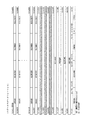
ここで、実行履歴データのフォーマットを図19に示す。実行履歴データのbit0からbit31には、障害を注入した時刻を示すHOUR7(時)、MINUTE7(分)、SECOND7(秒)、MILLSEC7(ミリ秒)が含まれる。bit32からbit255にも、同様に、障害を注入した時刻を示すデータが含まれる。ここでは、一例として、最大8回分の時刻を示すデータを含むことにしているが、これより少ないデータを含むようにしてもよいし、これより多くのデータを含むようにしてもよい。なお、実行履歴記録部184は、9回目以降の障害注入時には、初回の分から上書きするようにして最新の8回分を記録する。
Here, the format of the execution history data is shown in FIG.
ステップS271の後、ステップS215〜S219の処理が実行される。ステップS215〜S219の処理は、実施の形態1と同様である。 After step S271, steps S215 to S219 are executed. The processing in steps S215 to S219 is the same as that in the first embodiment.
検証端末16が障害シミュレータ11にステータスデータ要求コマンドを送信すると、障害シミュレータ11は、現在の設定や、障害注入の結果を示すステータスデータを生成し、検証端末16へ送信する。
When the
ここで、ステータスデータ要求コマンドのフォーマットを図20に示す。例えば、ステータスデータ要求コマンドのbit0には、ステータスデータを要求するかどうかを示すRQSTSが含まれる。
Here, the format of the status data request command is shown in FIG. For example,
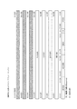
また、ここで、ステータスデータのフォーマットを図21に示す。例えば、ステータスデータののbit0からbit159には、障害注入指示コマンドと同様に、FTYPE、INJSTART、FMODE、SCSICMD、MDNUM、MDTIME、DLYTIME、FCPORT、SCSIADRが含まれる。bit256からbit511には、実行履歴データと同様に、障害を注入した時刻を示すデータが含まれる。ここでは、一例として、最大8回分の時刻を示すデータを含むことにしているが、これより少ないデータを含むようにしてもよいし、これより多くのデータを含むようにしてもよい。
Here, the format of the status data is shown in FIG. For example, the
図22は、ステータスデータを送信する際の障害シミュレータ11の動作を示すフローチャートである。
FIG. 22 is a flowchart showing the operation of the
障害シミュレータ11は、検証端末16からUSB22を介してステータスデータ要求コマンドが送信されると、検証端末I/F181を介してステータスデータ要求コマンドを受信して(ステップS501)、記憶装置で保持する(ステップS502)。
When a status data request command is transmitted from the
ステータスデータ生成部183は、記憶装置からステータスデータ要求コマンドを読み出し、ステータスデータ要求コマンドのRQSTSビットを処理装置により確認する(ステップS503)。RQSTSビットが0であれば、コマンドは無効であるので、処理を終了する。RQSTSビットが1であれば、ステータスデータ生成部183は、ステータスデータの生成処理を開始する。
The status
ステータスデータ生成部183は、実行履歴記録部184により記憶装置に保存されている実行履歴データを読み出して保持する(ステップS504)。また、ステータスデータ生成部183は、障害注入設定部182により記憶装置に保存されている直近の(即ち、障害注入設定部182が最後に受信した)障害注入指示コマンドを読み出し、障害注入指示コマンドで設定されている内容(データ)を保持する(ステップS505)。ステータスデータ生成部183は、ステップS504、S505で保持したデータを合わせてステータスデータを生成する(ステップS506)。そして、ステータスデータ生成部183は、生成したステータスデータを検証端末I/F181を介して検証端末16へ送信する(ステップS507)。
The status
検証端末16は、障害シミュレータ11から送信されたステータスデータを受信して、例えば、出力装置により出力する。検証端末16のユーザは、出力されたステータスデータを見ることにより、障害シミュレータ11がどのような間隔でどのような障害を発生させたかを知ることができる。
The
上記のように、本実施の形態において、検証端末16は、障害シミュレータ11から情報を収集する。障害シミュレータ11の制御部131は、擬似障害を発生させる度に、時刻を記録し、記録した時刻の一覧を履歴情報として検証端末16へ出力する。
As described above, in the present embodiment, the
以上説明したように、本実施の形態では、検証端末16が、障害シミュレータ11で実行された障害注入処理に関する情報を獲得する。これにより、二重系システムにおいて系切り替え試験を実施したときに、試験結果の検証のために有用な情報となる、障害注入に関する設定情報や障害注入の履歴を獲得することができる。
As described above, in the present embodiment, the
実施の形態5.
本実施の形態について、主に実施の形態1との差異を説明する。
Embodiment 5 FIG.
In the present embodiment, differences from the first embodiment will be mainly described.
図23は、本実施の形態に係る障害シミュレータ11の構成を示すブロック図である。
FIG. 23 is a block diagram showing a configuration of the
図23において、障害シミュレータ11は、実施の形態1と同様の構成要素に加えて、FCP_CMND記録部194を備える。
In FIG. 23, the
実施の形態1では、ディスクA14の特定のエリアを指定することで障害注入の対象となるコマンドを限定していた。試験のときに、特定のエリアではなく、特定のファイルにアクセスすることを試験項目として設定している場合には、そのファイルとディスクA14のエリア(SCSIADR)を関連付ける必要がある。本実施の形態では、検証端末16が、特定のファイルにアクセスすることが試験項目として設定されているときに、障害注入指示コマンドを発行するのに必要な情報を得る機能を有する。
In the first embodiment, a command to be injected with a fault is limited by designating a specific area of the disk A14. When the test item is set to access a specific file instead of a specific area at the time of the test, it is necessary to associate the file with the area of the disk A14 (SCSIIADR). In the present embodiment, the
以下では、試験システム10の動作について、障害タイプ「応答遅延」を例に説明するが、障害タイプが「無応答」、「リンク断」、「応答異常」であっても同様の動作が可能である。また、以下では、障害注入指示コマンドが、ディスクA14の特定エリアからのリード処理が行われる際に障害を発生させるよう指示するものである場合について説明するが、障害注入指示コマンドが、ディスクA14の特定エリアへのライト処理が行われる際に障害を発生させるよう指示するものである場合についても同様である。 In the following, the operation of the test system 10 will be described using the failure type “response delay” as an example, but the same operation is possible even if the failure type is “no response”, “link disconnection”, or “response abnormality”. is there. In the following, a case will be described in which the failure injection instruction command instructs to generate a failure when a read process from a specific area of the disk A14 is performed. The same applies to a case in which a failure is instructed when a write process to a specific area is performed.
検証端末16は、USB22を介して障害シミュレータ11にFCP_CMNDモニタ要求コマンドを送信する。障害シミュレータ11は、FCP_CMNDモニタ要求コマンドを受信すると、FCP_CMNDモニタ要求コマンドがFCP_CMNDのモニタの開始を要求するものであるか、あるいは、FCP_CMNDのモニタの停止を要求するものであるかを確認する。FCP_CMNDモニタ要求コマンドがFCP_CMNDのモニタの開始を要求するものであれば、障害シミュレータ11は、サーバA12から受信するデータをモニタし、FCP_CMNDを受信した場合には、FCP_CMNDを保持する。一方、FCP_CMNDモニタ要求コマンドがFCP_CMNDのモニタの停止を要求するものであれば、障害シミュレータ11は、保持している複数のFCP_CMNDからFCP_CMNDログを生成して検証端末16へ送信する。検証端末16は、FCP_CMNDログを解析し、障害注入指示コマンドの作成に必要な情報を取得する。
The
ここで、FCP_CMNDモニタ要求コマンドのフォーマットを図24に示す。例えば、FCP_CMNDモニタ要求コマンドのbit0には、FCP_CMNDのモニタの開始を要求するかどうかを示すMONSTARTが含まれる。bit1には、FCP_CMNDのモニタの停止を要求するかどうかを示すMONSTOPが含まれる。 Here, the format of the FCP_CMND monitor request command is shown in FIG. For example, bit0 of the FCP_CMND monitor request command includes MONSTART indicating whether or not to start monitoring of FCP_CMND. In bit1, MONSTOP indicating whether or not to stop monitoring of FCP_CMND is included.
また、ここで、FCP_CMNDログのフォーマットを図25に示す。例えば、FCP_CMNDログには、障害シミュレータ11がサーバA12から受信した複数のFCP_CMNDが受信時刻の順に記録される。
Here, the format of the FCP_CMND log is shown in FIG. For example, in the FCP_CMND log, a plurality of FCP_CMNDs received by the
図26は、障害シミュレータ11の動作を示すフローチャートである。
FIG. 26 is a flowchart showing the operation of the
障害注入設定部182は、FCP_CMNDモニタ要求コマンドを検証端末I/F181を介して検証端末16から受信すると、記憶装置に保存する(ステップS601)。制御部131は、記憶装置から直近の(即ち、障害注入設定部182が最後に受信した)FCP_CMNDモニタ要求コマンドを読み出し、FCP_CMNDモニタ要求コマンドのMONSTARTフィールドを処理装置により確認する(ステップS602)。MONSTARTフィールドが1になっていれば、制御部131は、モニタを開始する。MONSTARTフィールドが0であれば、制御部131は、モニタを開始せず、次のFCP_CMNDモニタ要求コマンドを待つ。
When receiving the FCP_CMND monitor request command from the
制御部131は、ステップS602でモニタ開始するにあたりFCP_CMND記録部194にモニタの開始を通知し、記憶装置に記録されているFCP_CMNDログをクリアする(記録されているFCP_CMNDを削除する)。制御部131は、データ選択部A152を制御し、第1データ経路173を選択するが、複データ保持部172にデータを保存するようにデータ保存部A111も制御する。データ保存部A111が複データ保持部172に保存したデータは、FCP_CMNDログの生成のために使われるのであり、データ送信部A102に出力されることはない。
When starting the monitoring in step S602, the
サーバA12においてディスクA14上にあるファイルXをリードするようなプログラムが実行されると、サーバA12からディスクA14に対してFCP_CMNDが発行される。障害シミュレータ11は、サーバA12から送信されたデータをデータ受信部A101で受信する。データ受信部A101は、受信したデータのデシリアライズ及びデコードを行う。データ受信部A101は、デコードを終えたデータを2バイトずつデータ保存部A111に送信する。データ保存部A111は、データ受信部A101から送られてきたデータを複データ保持部172に保存するとともにコマンド解析部141に直近の(即ち、最後に受信した)4バイトのデータを出力する(ステップS603、S604)。
When the server A12 executes a program that reads the file X on the disk A14, FCP_CMND is issued from the server A12 to the disk A14. The
制御部131は、記憶装置から直近の(即ち、障害注入設定部182が最後に受信した)FCP_CMNDモニタ要求コマンドを読み出し、FCP_CMNDモニタ要求コマンドのMONSTOPフィールドを処理装置により確認する(ステップS605)。MONSTOPフィールドが0になっていれば、制御部131は、モニタを継続する。
The
コマンド解析部141は、ステップS605で制御部131がモニタを継続する場合には、データ保存部A111から入力されてきた4バイトのデータを解析し、このデータがフレームの先頭であるかを処理装置により判定する(ステップS606)。具体的には、コマンド解析部141は、4バイトのデータがBCB5_5656hであれば、解析したデータがSOF、即ち、フレームの先頭であると判定する。コマンド解析部141が解析したデータがフレームの先頭でない場合、ステップS604に戻る。その後、次の2バイトが読み込まれ、ステップS606まで進んだ場合、コマンド解析部141は、その直前の2バイトと合わせた4バイトのデータを解析する。コマンド解析部141は、フレームの先頭を検出するまで同様の処理を繰り返す。
When the
データ保存部A111は、ステップS606でコマンド解析部141が解析したデータがフレームの先頭である場合、後続の4バイトのデータを複データ保持部172に保存する(ステップS607)。そして、データ保存部A111は、その4バイトのデータをコマンド解析部141に出力する。コマンド解析部141は、データ保存部A111から受け取ったデータを解析し、末尾の1バイトのデータ、即ち、フレームの先頭から8バイト目のR_CTLフィールドがFCP_CMNDを示すものであるかを処理装置により判定する(ステップS608)。具体的には、コマンド解析部141は、R_CTLフィールドが06hであれば、受信中のフレームがFCP_CMNDであると判定する。ステップS608でフレームがFCP_CMNDでない場合、ステップS604に戻る。その後、次の2バイトが読み込まれ、ステップS606まで進んだ場合、コマンド解析部141は、その直前の2バイトと合わせた4バイトのデータを解析する。コマンド解析部141は、フレームの先頭を検出すると、R_CTLフィールドを解析する。コマンド解析部141は、FCP_CMNDを検出するまで同様の処理を繰り返す。
When the data analyzed by the
データ保存部A111は、ステップS608でフレームがFCP_CMNDである場合、後続の60バイトのデータを複データ保持部172に保存する(ステップS609)。制御部131は、データ保存部A111でFCP_CMNDが保存されたことをFCP_CMND記録部194に通知する。FCP_CMND記録部194は、データ保存部A111が複データ保持部172に保存したFCP_CMNDを記録したFCP_CMNDログを生成する(ステップS610)。例えば、FCP_CMND記録部194は、データ保存部A111でFCP_CMNDが保存される度に、新たに保存されたFCP_CMNDをFCP_CMNDログの末尾に追加する。FCP_CMND記録部194は、FCP_CMNDログが予め割り当てられた容量を超える場合には、新たに保存されたFCP_CMNDを無視する。
If the frame is FCP_CMND in step S608, the data storage unit A111 stores the subsequent 60-byte data in the multiple data storage unit 172 (step S609). The
制御部131は、ステップS605でMONSTOPフィールドが1になっていれば、モニタを停止する。制御部131は、FCP_CMND記録部194により記録されたFCP_CMNDログを記憶装置から読み出し、検証端末I/F181を介して検証端末16へ送信する(ステップS611)。
If the MONSTOP field is 1 in step S605, the
検証端末16は、障害シミュレータ11から送信されたFCP_CMNDログを受信して、例えば、出力装置により出力する。検証端末16のユーザは、出力されたFCP_CMNDログを見ることにより、ファイルXにアクセスするときのSCSIアドレス、FCPORTに関する情報を入手することが可能になる。そして、この情報を利用して、検証端末16から障害シミュレータ11に送信する障害注入指示コマンドを作成することができる。
The
上記のように、本実施の形態において、検証端末16は、障害シミュレータ11から情報を収集する。障害シミュレータ11の制御部131は、コマンド解析部141により解析された1フレーム分のデータがFCP_CMNDであると判定される度に、当該データを記録し、記録したデータの一覧をログ情報として検証端末16へ出力する。
As described above, in the present embodiment, the
以上説明したように、本実施の形態では、検証端末16が、あるファイルへのアクセス時のFCP_CMNDのパラメータを得ることができる。これにより、障害注入指示コマンドの作成に必要な情報(SCSIADR、FCPORT等)を得ることができ、障害注入の限定条件がある特定のファイル名であるような試験でも実施が可能になる。
As described above, in this embodiment, the
以上、本発明の実施の形態について説明したが、これらのうち、2つ以上の実施の形態を組み合わせて実施しても構わない。あるいは、これらのうち、1つの実施の形態を部分的に実施しても構わない。あるいは、これらのうち、2つ以上の実施の形態を部分的に組み合わせて実施しても構わない。 As mentioned above, although embodiment of this invention was described, you may implement combining 2 or more embodiment among these. Alternatively, one of these embodiments may be partially implemented. Or you may implement combining two or more embodiment among these partially.
10 試験システム、11 障害シミュレータ、12 サーバA、13 サーバB、14 ディスクA、15 ディスクB、16 検証端末、101 データ受信部A、102 データ送信部A、103 データ送信部B、104 データ受信部B、111 データ保存部A、112 データ保存部B、131 制御部、141 コマンド解析部、142 データ解析部、151 代替送信データ出力部、152 データ選択部A、153 データ選択部B、154 データ置換部、161 コマンド送信遅延タイマ、162 障害注入遅延タイマ、163 障害注入回数カウンタ、171 単データ保持部、172 複データ保持部、173 第1データ経路、174 第2データ経路、175 第3データ経路、176 第4データ経路、177 第5データ経路、181 検証端末I/F、182 障害注入設定部、183 ステータスデータ生成部、184 実行履歴記録部、185 時計部、191 非IDLEフラグ、192 受信データ数カウンタ、193 D_ID保存部、194 FCP_CMND記録部、901 LCD、902 キーボード、903 マウス、904 FDD、905 CDD、906 プリンタ、911 CPU、912 バス、913 ROM、914 RAM、915 通信ボード、920 HDD、921 オペレーティングシステム、922 ウィンドウシステム、923 プログラム群、924 ファイル群。 DESCRIPTION OF SYMBOLS 10 Test system, 11 Failure simulator, 12 Server A, 13 Server B, 14 Disk A, 15 Disk B, 16 Verification terminal, 101 Data receiver A, 102 Data transmitter A, 103 Data transmitter B, 104 Data receiver B, 111 Data storage unit A, 112 Data storage unit B, 131 Control unit, 141 Command analysis unit, 142 Data analysis unit, 151 Alternative transmission data output unit, 152 Data selection unit A, 153 Data selection unit B, 154 Data replacement 161, command transmission delay timer, 162 fault injection delay timer, 163 fault injection count counter, 171 single data holding unit, 172 multiple data holding unit, 173 first data path, 174 second data path, 175 third data path, 176 4th data path, 177 5th data Path, 181 verification terminal I / F, 182 fault injection setting unit, 183 status data generation unit, 184 execution history recording unit, 185 clock unit, 191 non-IDLE flag, 192 received data number counter, 193 D_ID storage unit, 194 FCP_CMND recording 901 LCD, 902 keyboard, 903 mouse, 904 FDD, 905 CDD, 906 printer, 911 CPU, 912 bus, 913 ROM, 914 RAM, 915 communication board, 920 HDD, 921 operating system, 922 window system, 923 program group 924 file group.
Claims (13)
前記送信装置からデータを受信するデータ受信部と、
前記受信装置へデータを送信するデータ送信部と、
前記データ受信部により受信されたデータをバッファメモリに順次保存するデータ保存部と、
前記データ保存部により前記バッファメモリに保存されている、最先のデータから1フレーム分のデータを解析して当該1フレーム分のデータが所定のフレームであるかどうかを判定するデータ判定部と、
前記データ判定部により解析された1フレーム分のデータが前記所定のフレームでないと判定された場合、前記バッファメモリから最先のデータを取り出して前記データ送信部に送信させ、前記データ判定部により当該1フレーム分のデータが前記所定のフレームであると判定された場合、前記擬似障害を発生させる制御部とを備えることを特徴とする擬似障害発生装置。 A pseudo failure generator that is connected between a transmitting device that transmits a frame composed of a plurality of data and a receiving device that receives the frame, and generates a pseudo failure in communication using the frame,
A data receiver for receiving data from the transmitter;
A data transmission unit for transmitting data to the receiving device;
A data storage unit for sequentially storing data received by the data receiving unit in a buffer memory;
A data determination unit that analyzes data for one frame from the earliest data stored in the buffer memory by the data storage unit and determines whether the data for the one frame is a predetermined frame;
When it is determined that the data for one frame analyzed by the data determination unit is not the predetermined frame, the earliest data is extracted from the buffer memory and transmitted to the data transmission unit, and the data determination unit And a control unit that generates the pseudo-failure when it is determined that the data for one frame is the predetermined frame.
前記制御部は、前記データ判定部による判定の結果が出る度に、当該結果に応じて動作することを特徴とする請求項1に記載の擬似障害発生装置。 If the data for the analyzed frame is not the predetermined frame, the data determination unit is stored in the buffer memory by the data storage unit, and the control unit extracts the earliest data. Analyzing the data for one frame from the data that has become the earliest data to determine whether the data for the one frame is the predetermined frame,
The pseudo-fault generating apparatus according to claim 1, wherein the control unit operates in accordance with a result of the determination by the data determination unit every time the result is determined.
前記データ保存部により保存されたデータの代わりとなるデータを生成するデータ生成部を備え、
前記制御部は、前記データ保存部により前記バッファメモリに保存されているデータが1フレーム分に満たない場合、前記データ生成部により生成されたデータを前記データ送信部に送信させることを特徴とする請求項1又は2に記載の擬似障害発生装置。 The simulated fault generator further includes:
A data generation unit that generates data instead of the data stored by the data storage unit;
The control unit causes the data transmission unit to transmit the data generated by the data generation unit when the data stored in the buffer memory by the data storage unit is less than one frame. The simulated fault generator according to claim 1 or 2.
前記所定のフレームに対して前記受信装置から返信されるフレームを前記送信装置へ転送するデータ転送部を備え、
前記制御部は、前記データ判定部により解析された1フレーム分のデータが前記所定のフレームであると判定された場合、当該1フレーム分のデータを前記データ送信部に送信させ、当該1フレーム分のデータに対して前記受信装置から返信されるフレームを前記データ転送部に転送させる際に、当該フレームの一部のデータを変更することで前記擬似障害を発生させることを特徴とする請求項1から3までのいずれかに記載の擬似障害発生装置。 The simulated fault generator further includes:
A data transfer unit for transferring a frame returned from the receiving device to the transmitting device with respect to the predetermined frame;
When it is determined that the data for one frame analyzed by the data determination unit is the predetermined frame, the control unit causes the data transmission unit to transmit the data for the one frame, and 2. The pseudo failure is generated by changing a part of data of the frame when transferring a frame returned from the receiving apparatus to the data transfer unit for the data of 1. 4. The simulated fault generator according to any one of items 1 to 3.
前記制御部は、前記端末装置からの信号で指定された時間が経過するまで待機してから動作し始めることを特徴とする請求項1から6までのいずれかに記載の擬似障害発生装置。 The simulated fault generation device is further connected to a terminal device that inputs a signal designating time to the simulated fault generation device,
The pseudo-failure generating apparatus according to any one of claims 1 to 6, wherein the control unit starts operating after waiting until a time designated by a signal from the terminal device elapses.
前記制御部は、前記データ判定部により解析された1フレーム分のデータが前記所定のフレームであると判定された場合、毎回前記擬似障害を発生させる代わりに前記端末装置からの信号で指定された頻度で前記擬似障害を発生させることを特徴とする請求項1から7までのいずれかに記載の擬似障害発生装置。 The simulated fault generation device is further connected to a terminal device that inputs a signal specifying a frequency to the simulated fault generation device,
When it is determined that the data for one frame analyzed by the data determination unit is the predetermined frame, the control unit is designated by a signal from the terminal device instead of generating the pseudo failure every time. The simulated fault generator according to any one of claims 1 to 7, wherein the simulated fault is generated at a frequency.
前記制御部は、前記擬似障害を発生させる度に、時刻を記録し、記録した時刻の一覧を履歴情報として前記端末装置へ出力することを特徴とする請求項1から8までのいずれかに記載の擬似障害発生装置。 The simulated fault generation device is further connected to a terminal device that collects information from the simulated fault generation device,
9. The control unit according to claim 1, wherein the control unit records a time each time the pseudo failure occurs, and outputs a list of the recorded times to the terminal device as history information. Pseudo-fault generator.
前記制御部は、前記データ判定部により解析された1フレーム分のデータが前記所定のフレームであると判定される度に、当該データを記録し、記録したデータの一覧をログ情報として前記端末装置へ出力することを特徴とする請求項1から9までのいずれかに記載の擬似障害発生装置。 The simulated fault generation device is further connected to a terminal device that collects information from the simulated fault generation device,
The control unit records the data every time it is determined that the data for one frame analyzed by the data determination unit is the predetermined frame, and the terminal device uses the recorded data list as log information. The pseudo-fault generating device according to claim 1, wherein the pseudo-fault generating device according to claim 1 is output.
前記擬似障害発生装置が、前記送信装置からデータを受信し、
前記擬似障害発生装置が、受信したデータをバッファメモリに順次保存し、
前記擬似障害発生装置が、前記バッファメモリに保存されている、最先のデータから1フレーム分のデータを解析して当該1フレーム分のデータが所定のフレームであるかどうかを判定し、
前記擬似障害発生装置が、解析した1フレーム分のデータが前記所定のフレームでない場合、前記バッファメモリから最先のデータを取り出して前記受信装置へ送信し、当該1フレーム分のデータが前記所定のフレームである場合、前記擬似障害を発生させることを特徴とする擬似障害発生方法。 Pseudo fault occurrence in which a pseudo fault generating apparatus connected between a transmitting apparatus that transmits a frame composed of a plurality of data and a receiving apparatus that receives the frame generates a pseudo fault in communication using the frame A method,
The simulated fault generator receives data from the transmitter;
The pseudo-failure generator sequentially stores received data in a buffer memory,
The pseudo-failure generator analyzes data for one frame from the earliest data stored in the buffer memory to determine whether the data for the one frame is a predetermined frame;
When the simulated failure generating device does not analyze one frame of data that is not the predetermined frame, it extracts the earliest data from the buffer memory and transmits the data to the receiving device. In the case of a frame, the simulated fault generation method characterized by generating the simulated fault.
前記送信装置からデータを受信するデータ受信処理と、
前記受信装置へデータを送信するデータ送信処理と、
前記データ受信処理により受信されたデータをバッファメモリに順次保存するデータ保存処理と、
前記データ保存処理により前記バッファメモリに保存されている、最先のデータから1フレーム分のデータを処理装置により解析して当該1フレーム分のデータが所定のフレームであるかどうかを判定するデータ判定処理と、
前記データ判定処理により解析された1フレーム分のデータが前記所定のフレームでないと判定された場合、前記バッファメモリから最先のデータを取り出して前記データ送信処理に送信させ、前記データ判定処理により当該1フレーム分のデータが前記所定のフレームであると判定された場合、前記擬似障害を前記処理装置により発生させる制御処理とをコンピュータに実行させることを特徴とする擬似障害発生プログラム。 A pseudo-failure generation program that is executed by a computer connected between a transmission device that transmits a frame composed of a plurality of data and a reception device that receives the frame, and generates a pseudo-failure in communication using the frame Because
A data reception process for receiving data from the transmission device;
A data transmission process for transmitting data to the receiving device;
A data storage process for sequentially storing the data received by the data reception process in a buffer memory;
Data determination for determining whether the data for one frame from the earliest data stored in the buffer memory by the data storage processing is analyzed by a processing device and whether the data for the one frame is a predetermined frame Processing,
When it is determined that the data for one frame analyzed by the data determination process is not the predetermined frame, the earliest data is extracted from the buffer memory and transmitted to the data transmission process, and the data determination process When it is determined that data for one frame is the predetermined frame, a simulated fault occurrence program causing a computer to execute a control process for causing the processing device to generate the simulated fault.
前記擬似障害発生装置は、
前記送信装置からデータを受信するデータ受信部と、
前記受信装置へデータを送信するデータ送信部と、
前記端末装置により前記試験の開始を指示された場合、前記データ受信部により受信されたデータをバッファメモリに順次保存するデータ保存部と、
前記データ保存部により前記バッファメモリに保存されている、最先のデータから1フレーム分のデータを解析して当該1フレーム分のデータが所定のフレームであるかどうかを判定するデータ判定部と、
前記データ判定部により解析された1フレーム分のデータが前記所定のフレームでないと判定された場合、前記バッファメモリから最先のデータを取り出して前記データ送信部に送信させ、前記データ判定部により当該1フレーム分のデータが前記所定のフレームであると判定された場合、前記擬似障害を発生させる制御部とを備えることを特徴とする試験システム。 A transmission device that transmits a frame composed of a plurality of data, a reception device that receives the frame, and a pseudo device that is connected between the transmission device and the reception device and generates a pseudo failure in communication using the frame. A test system comprising a failure generation device and a terminal device connected to the pseudo failure generation device and instructing start of a test,
The simulated fault generator is
A data receiver for receiving data from the transmitter;
A data transmission unit for transmitting data to the receiving device;
When instructed to start the test by the terminal device, a data storage unit that sequentially stores data received by the data reception unit in a buffer memory;
A data determination unit that analyzes data for one frame from the earliest data stored in the buffer memory by the data storage unit and determines whether the data for the one frame is a predetermined frame;
When it is determined that the data for one frame analyzed by the data determination unit is not the predetermined frame, the earliest data is extracted from the buffer memory and transmitted to the data transmission unit, and the data determination unit A test system comprising: a control unit that generates the pseudo-fault when it is determined that one frame of data is the predetermined frame.
Priority Applications (1)
| Application Number | Priority Date | Filing Date | Title |
|---|---|---|---|
| JP2009282462A JP2011123783A (en) | 2009-12-14 | 2009-12-14 | Device, method and program for generating simulated fault, and test system |
Applications Claiming Priority (1)
| Application Number | Priority Date | Filing Date | Title |
|---|---|---|---|
| JP2009282462A JP2011123783A (en) | 2009-12-14 | 2009-12-14 | Device, method and program for generating simulated fault, and test system |
Publications (1)
| Publication Number | Publication Date |
|---|---|
| JP2011123783A true JP2011123783A (en) | 2011-06-23 |
Family
ID=44287593
Family Applications (1)
| Application Number | Title | Priority Date | Filing Date |
|---|---|---|---|
| JP2009282462A Pending JP2011123783A (en) | 2009-12-14 | 2009-12-14 | Device, method and program for generating simulated fault, and test system |
Country Status (1)
| Country | Link |
|---|---|
| JP (1) | JP2011123783A (en) |
Cited By (1)
| Publication number | Priority date | Publication date | Assignee | Title |
|---|---|---|---|---|
| CN108038317A (en) * | 2017-12-18 | 2018-05-15 | 广东科鉴检测工程技术有限公司 | Precision instrument performance parameter retention period Forecasting Methodology and system |
-
2009
- 2009-12-14 JP JP2009282462A patent/JP2011123783A/en active Pending
Cited By (1)
| Publication number | Priority date | Publication date | Assignee | Title |
|---|---|---|---|---|
| CN108038317A (en) * | 2017-12-18 | 2018-05-15 | 广东科鉴检测工程技术有限公司 | Precision instrument performance parameter retention period Forecasting Methodology and system |
Similar Documents
| Publication | Publication Date | Title |
|---|---|---|
| US7610515B2 (en) | Disk array device and failure response verification method thereof | |
| JP4371724B2 (en) | Storage system and storage device system | |
| CN101651559B (en) | Failover method of storage service in double controller storage system | |
| KR101196547B1 (en) | A method for deterministic sas discovery and configuration | |
| US20120233399A1 (en) | Storage apparatus and method of controlling the same | |
| US7107343B2 (en) | Method and apparatus for improved RAID 1 write performance in low cost systems | |
| CN112667066B (en) | Method, system and medium for expanding hard disk storage capacity | |
| US8032793B2 (en) | Method of controlling information processing system, information processing system, direct memory access control device and program | |
| EP1681625A2 (en) | Redundant storage virtualization subsystem and computer system having the same | |
| CN117094038B (en) | Programmable logic device and server | |
| CN105007307A (en) | Storage control method and system | |
| CN108363477A (en) | Server power-up state monitors system and method, computer storage and equipment | |
| JP4433372B2 (en) | Data access system and method | |
| JP4443200B2 (en) | Information system | |
| US20110191641A1 (en) | Raid device, abnormal device detecting apparatus, and abnormal device detecting method | |
| JP2007207062A (en) | Data reliability improvement method and information processing apparatus using the method | |
| JP2011123783A (en) | Device, method and program for generating simulated fault, and test system | |
| US20090132866A1 (en) | Storage apparatus | |
| US8943255B2 (en) | Methods and structure for accounting for connection resets between peripheral component interconnect express bridges and host devices | |
| CN113434442A (en) | A switch and data access method | |
| JP4413806B2 (en) | Fault isolation method, communication apparatus and program having fault isolation function | |
| JP2001346181A (en) | Data storage unit sharing device and program recording medium | |
| CN103858105B (en) | connection method | |
| CN102200888B (en) | Virtual memory, and virtual storage system and method | |
| JP7448815B2 (en) | Information processing system, storage device, host device, and program |