JP2011123722A - Security thread, security paper sheet and verification method - Google Patents
Security thread, security paper sheet and verification method Download PDFInfo
- Publication number
- JP2011123722A JP2011123722A JP2009281579A JP2009281579A JP2011123722A JP 2011123722 A JP2011123722 A JP 2011123722A JP 2009281579 A JP2009281579 A JP 2009281579A JP 2009281579 A JP2009281579 A JP 2009281579A JP 2011123722 A JP2011123722 A JP 2011123722A
- Authority
- JP
- Japan
- Prior art keywords
- magnetic
- information
- layer
- hologram
- security
- Prior art date
- Legal status (The legal status is an assumption and is not a legal conclusion. Google has not performed a legal analysis and makes no representation as to the accuracy of the status listed.)
- Pending
Links
Images
Landscapes
- Credit Cards Or The Like (AREA)
- Inspection Of Paper Currency And Valuable Securities (AREA)
- Paper (AREA)
Abstract
【課題】単にホログラムなどの光学的な機能を持たせたセキュリティスレッドではなく、磁気情報をも記録できるようにして、ホログラムなどが持っている光学的な情報を磁気情報としてセキュリティスレッドに記録させ、光学的な情報と磁気情報を読み取り、比較する事ができるようにすることで、より偽造することが困難なセキュリティスレッドを提供することを課題とする。
【解決手段】基材上の一方の面に、反射層またはホログラムまたは回折格子を設け、他方の面に磁性材料を主成分とする磁性層を設けてなることを特徴とするセキュリティスレッド。
【選択図】図1[PROBLEMS] To record not only a security thread having an optical function such as a hologram but also magnetic information, and recording the optical information possessed by the hologram or the like as magnetic information on the security thread, It is an object to provide a security thread that is more difficult to forge by making it possible to read and compare optical information and magnetic information.
A security thread comprising a reflective layer, a hologram, or a diffraction grating on one surface of a base material, and a magnetic layer containing a magnetic material as a main component on the other surface.
[Selection] Figure 1
Description
本発明は、紙幣、有価証券等に漉き込んで使用される偽造防止用のセキュリティスレッド及びそれを用いたセキュリティ用紙並びにその検証法に関する。 The present invention relates to a security thread for preventing counterfeiting used in banknotes, securities and the like, a security paper using the security thread, and a verification method thereof.
従来から、セキュリティスレッドは、紙幣や有価証券において、その用紙に漉き込んで偽造防止用のセキュリティとして利用されている。例えば、セキュリティスレッドにホログラムを用いれば、カラーコピーやスキャナによる画像取り込みでは再現が難しいことを利用して、偽造防止技術として取り入れられている。これは、主に目視での真偽判定に利用するものである。 Conventionally, a security thread has been used as security for preventing counterfeiting in banknotes and securities by encroaching on the paper. For example, if a hologram is used for the security thread, it is adopted as a forgery prevention technique by taking advantage of the fact that it is difficult to reproduce by color copy or image capture by a scanner. This is mainly used for visual authenticity determination.
一方、ATM等に設けられた読取機で検証を行うための方法としては、セキュリティスレッドに磁性層を設ける方法がある。例えば、特許文献1には、セキュリティスレッドに磁気バーコードを設ける方法が提案されている。また、特許文献2および3には、複数層の磁性材料を用いたり複数のセキュリティスレッドを設けたりして、それらの磁気情報を読取ることで真偽判定を行う方法が提案されている。
On the other hand, as a method for performing verification by a reader provided in ATM or the like, there is a method of providing a magnetic layer on a security thread. For example,
しかし、前記した技術では、例えばコピー防止のホログラムでも、性能が向上した近年のデジタルカラーコピー機であれば、ホログラム特有の奥行きのある画像の再現は困難であるが、金属光沢がよく再現される上に、一見しただけでは本物と見間違えるぐらいの精巧なコピーが得られることがある。また、昨今の技術の向上により、本物とほとんど同じような外観のホログラムを得ることもできなくはないため、コピーによらずとも偽造は可能であり、単にホログラム付きのセキュリティスレッドとするだけでは、有効な偽造防止策とはいい難くなってきている。 However, with the above-described technology, for example, even with a copy-preventing hologram, if a recent digital color copier with improved performance is difficult to reproduce a deep image peculiar to the hologram, the metallic luster is reproduced well. On top of that, you may get an elaborate copy that can be mistaken for the real thing at first glance. In addition, due to the recent improvement in technology, it is not possible to obtain a hologram with almost the same appearance as the real thing, so it is possible to forge without relying on a copy, just by making it a security thread with a hologram, Effective anti-counterfeiting measures are becoming difficult.
また、機械読取り用にセキュリティスレッドに磁気情報を設ける方法では、バーコードを設ける程度であればよいが、複数層の磁性材料を用いたり複数本のセキュリティスレッドを設けたりするのは構成が非常に複雑でコストアップ要因である。また、磁性材料は容易に入手できるものもあり、本当に特殊な磁気特性を有するものでない限り、似て非なるものを作成することは不可能ではない。その上に、表面に単にホログラム等の画像を設けたとしても、これを単に目視検証用に用いるのみでは、本質的には従来のホログラムを用いた目視判定によるセキュリティスレッドと大きな差はないと言える。 In addition, in the method of providing magnetic information on the security thread for machine reading, it is only necessary to provide a bar code, but using multiple layers of magnetic material or providing multiple security threads is very structural. This is a complicated and expensive factor. Also, some magnetic materials are readily available, and it is not impossible to create something that is not similar unless it really has special magnetic properties. On top of that, even if an image such as a hologram is simply provided on the surface, it can be said that there is essentially no significant difference from a security thread based on visual judgment using a conventional hologram if it is simply used for visual verification. .
上記問題を解決するため、本発明は、ホログラムなどの光学的な機能を持たせたセキュリティスレッドに磁気情報も記録できる機能を付加することにより、ホログラムなどが持っている光学的な情報を磁気情報としてセキュリティスレッドに記録し、光学的な情報と磁気情報を比較して真偽判定することで、偽造することがより困難なセキュリティスレッドを提供することを課題とする。 In order to solve the above problems, the present invention adds a function capable of recording magnetic information to a security thread having an optical function such as a hologram, thereby converting the optical information possessed by the hologram into magnetic information. It is an object of the present invention to provide a security thread that is more difficult to forge by recording in a security thread and comparing the optical information and magnetic information to determine authenticity.
上記の課題を解決するため、請求項1に記載の発明は、基材上の一方の面に、ホログラムまたは回折格子を設け、他方の面に磁性材料を主成分とする磁性層を設けてなることを特徴とするセキュリティスレッドである。
In order to solve the above problems, the invention according to
また、請求項2に記載の発明は、基材上の一方の面に、反射層を設け、他方の面に磁性材料を主成分とする磁性層を設けてなり、かつ前記反射層の一部を除去してなることを特徴とするセキュリティスレッドである。 According to a second aspect of the present invention, a reflective layer is provided on one surface of a substrate, a magnetic layer mainly composed of a magnetic material is provided on the other surface, and a part of the reflective layer is provided. It is a security thread characterized by removing.
また、請求項3に記載の発明は、前記磁性層には、前記ホログラムまたは回折格子または前記反射層と同期する情報が記録されていることを特徴とする請求項1または2に記載のセキュリティスレッドである。 According to a third aspect of the present invention, in the security thread according to the first or second aspect, information synchronized with the hologram, the diffraction grating, or the reflective layer is recorded in the magnetic layer. It is.
また、請求項4に記載の発明は、前記磁性層が、前記ホログラムまたは前記回折格子または前記反射層と同期する状態でパターン状に設けられていることを特徴とする請求項1または2に記載のセキュリティスレッドである。 The invention according to claim 4 is characterized in that the magnetic layer is provided in a pattern in a state of being synchronized with the hologram, the diffraction grating, or the reflective layer. Security thread.
また、請求項5に記載の発明は、前記磁性層には、前記ホログラムまたは前記回折格子または前記反射層による反射光情報と同一または任意のアルゴリズムで反射光情報に変換可能な情報が記録されてなることを特徴とする請求項1乃至4のいずれか1項に記載のセキュリティスレッドである。
According to a fifth aspect of the present invention, information that can be converted into reflected light information by the same or an arbitrary algorithm as the reflected light information by the hologram, the diffraction grating, or the reflective layer is recorded on the magnetic layer. The security thread according to any one of
また、請求項6に記載の発明は、請求項1乃至6のいずれか1項に記載のセキュリティスレッドを漉き込んだことを特徴とするセキュリティ用紙である。 According to a sixth aspect of the present invention, there is provided a security sheet comprising the security thread according to any one of the first to sixth aspects.
また、請求項7に記載の発明は、請求項1乃至5のいずれか1項に記載のセキュリティスレッドまたは請求項6に記載のセキュリティ用紙の検証方法であって、前記ホログラムまたは前記回折格子または前記反射層に光を照射して得られる反射光(回折光を含む)を受光して得た反射光情報と同一または任意のアルゴリズムで変換した信号と、前記磁性層に記録されている磁気情報を反映した信号について、両者の位相差の一定性と周期の一致性を判定することで真偽判定を行うことを特徴とする検証方法である。
The invention according to
本発明によれば、表面にホログラムまたは回折格子または反射層と、ホログラムまたは回折格子または反射層を除去した部分を設けたため、その反射光または回折光の有無により反射光情報を再生することが可能であり、また、反射光情報を元にして任意のアルゴリズムで変換される情報を裏面の磁性層に磁気情報として記録し、これを読み取って比較することで真偽判定が可能であるため、より高いセキュリティ性を付与することができる。 According to the present invention, since the hologram, diffraction grating, or reflection layer and the portion from which the hologram, diffraction grating, or reflection layer has been removed are provided on the surface, it is possible to reproduce reflected light information depending on the presence or absence of the reflected light or diffracted light. In addition, since information converted by an arbitrary algorithm based on reflected light information is recorded as magnetic information in the magnetic layer on the back surface, and this can be determined by reading and comparing, High security can be imparted.
以下、図面を参照して発明を詳細に説明する。
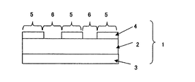
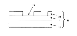
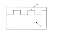
図1は、本発明によってなるセキュリティスレッド1の構成の一例を示す断面図である。セキュリティスレッド1は、基材2の一方の面に磁性層3、他方の面に反射層4が設けられている。反射層4は部分的に設けられているので、反射部5と非反射部6が同一面に存在する。
Hereinafter, the invention will be described in detail with reference to the drawings.
FIG. 1 is a cross-sectional view showing an example of the configuration of a
基材2は、反射層4及び磁性層3の支持体となるもので、従来公知のプラスチック素材や紙材料の類のものが利用可能であるが、一般的には入手性、コスト、強度といった面を考慮して、3〜50μm厚程度のポリエチレンテレフタレート(以下、PETと略す)フィルムを用いるのが好適であるが、これに限るものではない。反射層4に悪影響を与えないため、基材2の表面は平滑であることが好ましいが、平滑性が低い場合は、適宜、平滑層を併用しても良い。また、基材2と磁性層3及び反射層4との密着性を良好にするため、従来公知のアンカー層を設けたり、基材2の表面をコロナ処理しても良い。
The
磁性層3は、従来公知の磁性粉とバインダー樹脂を主成分として形成される。磁性粉としては、例えば、鉄、γ―酸化鉄、マグネタイト、Co被着−γ酸化鉄、バリウムフェライト、ストロンチウムフェライト、アルニコ等の硬磁性体が使用可能である。
The
反射層4は通常は表面に設けられるものである。反射層4を設ける方法としては、アルミニウム等の金属薄膜を形成する方法が一般的であるが、これに限るものではない。反射層4の上に、耐久性を付与するための保護層や金属薄膜と樹脂間の密着性を向上させるためのアンカー層を設けることはもちろん差し支えない。 The reflective layer 4 is usually provided on the surface. As a method of providing the reflective layer 4, a method of forming a metal thin film such as aluminum is common, but is not limited thereto. Of course, a protective layer for imparting durability and an anchor layer for improving the adhesion between the metal thin film and the resin may be provided on the reflective layer 4.
かかる反射層4は連続ではなく部分的に設けられる。したがって、図1に示すように、反射層4が無い部分は、下地となる基材2または磁性層3の色相が観察される。また、その部分は反射層4の反射が殆ど無いので、適切な光源による照射光による十分な強度の反射光が得られないことを利用し、反射の有無で情報を記録することができる。反射層4を部分的に設ける方法としては、例えば部分的に蒸着を施す方法、マスク印刷を施してエッチングをする方法、レーザー等の光線で破壊する方法、サーマルヘッド等で熱破壊する方法、光沢のあるインキを部分的に設ける方法等があり、必要に応じて選択可能である。
Such a reflective layer 4 is provided not partially but partially. Therefore, as shown in FIG. 1, the hue of the
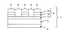
図2も、上記セキュリティスレッドの構成の一例を示す断面図である。基材2の一方の面に磁性層3、もう一方の面に反射層4が設けられているが、その反射層4は、蒸着アンカー層11、金属蒸着層12、マスク層13から構成されている例を示している。蒸着アンカー層11は、金属蒸着層12と基材2の密着性が十分であれば不要である。金属蒸着
層12は一旦全面に設けられ、その上に所望の形状のマスク層13を設ける。マスク層とは、エッチングマスクのことを指しており、その下地にある金属蒸着層をエッチングして除去する際のエッチングマスクとして機能する層である。マスク層13を設ける方法としては、例えば通常の印刷法が利用可能で、一例としてはグラビア印刷法、スクリーン印刷法、オフセット印刷法、フレキソ印刷法等々の方法が必要に応じて選択される。マスク層13を設けた後に、エッチング液に浸漬し、金属蒸着層12の露出部分を溶解すると、マスク層13の形状に沿った形で金属蒸着層12を残すことができる。
FIG. 2 is also a cross-sectional view showing an example of the configuration of the security thread. A
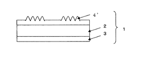
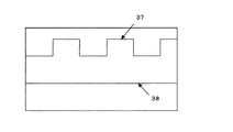
図3も、本発明によってなるセキュリティスレッド1の構成の一例を示す断面図である。セキュリティスレッド1は、基材2の一方の面にホログラムまたは回折格子4’、他方の面に磁性層3が設けられている。ホログラムまたは回折格子4’は部分的に設けられているので、反射部5と非反射部6に相当する、ホログラムまたは回折格子がある部分とそれが無い部分が同一面に存在する。また、回折格子は、微小な回折格子の集合体でも良く、それら微小な回折格子の向きを設定することにより、画像や文字を現したり、設定したい情報を反映したものにすることができる。図3は、ホログラムまたは回折格子4’が、部分的に設けられている例を示しているが、全面または広い範囲に形成されていても良い。その理由は、ホログラムでは、画像情報を反映した回折格子であるため、像情報を反映した情報を含んでいるためである。回折格子の場合、回折方向が異なる微細な回折格子を組み合わせて、画像、文字、模様、などの情報を含ませている場合は、ホログラムの場合と同様となる。
FIG. 3 is also a cross-sectional view showing an example of the configuration of the
基材2は、ホログラムまたは回折格子4’及び磁性層3の支持体となるもので、従来公知のプラスチック素材や紙材料の類のものが利用可能であるが、一般的には入手性、コスト、強度といった面を考慮して、3〜50μm厚程度のポリエチレンテレフタレート(以下、PETと略す)フィルムが用いるのが好適であるが、これに限るものではない。基材2は表面が平滑であることが好ましいが、平滑化のための平滑層を設ける等すれば、その平滑性はある程度低くてもかまわない。
The
ホログラムまたは回折格子4’を設ける方法としては、予めスタンパーに形成したホログラムまたは回折格子の形状を、熱圧を介して樹脂上に複製(転写)し、アルミニウム等の金属薄膜を形成する方法が一般的であるが、これに限るものではない。ホログラムまたは回折格子4’の上に、耐久性を付与するための保護層や金属薄膜と樹脂間の密着性を向上させるためのアンカー層を設けることはもちろん差し支えない。また、読取に使用するホログラムまたは回折格子4’以外にも、読取を邪魔しない範囲で他のホログラム画像や別の回折格子を設けても差し支えない。例えば、空間周波数や回折方向が異なるものは読取に影響を与えない場合が多いため、同じ面に設けることができる。 As a method of providing the hologram or diffraction grating 4 ′, a method of forming a metal thin film such as aluminum by copying (transferring) the shape of the hologram or diffraction grating previously formed on the stamper onto the resin via hot pressure is generally used. But not limited to this. Of course, a protective layer for imparting durability and an anchor layer for improving the adhesion between the metal thin film and the resin may be provided on the hologram or the diffraction grating 4 '. In addition to the hologram or diffraction grating 4 'used for reading, other hologram images or other diffraction gratings may be provided within a range that does not interfere with reading. For example, those having different spatial frequencies and diffraction directions often do not affect reading, and can be provided on the same surface.
ホログラムまたは回折格子4’の回折は、入射角α(法線と入射光がなす角)、回折角β(法線と回折光がなす角)、入射光の波長λ、回折格子の間隔dが式1の関係で示される。ここで、入射角を法線方向にとれば、α=0なので、sinα=0なので、例えば、635nmのレーザー光で1μm間隔の回折格子に法線方向から入射すると、およそθ=±40度に回折光が現れるので、この角度で受光すればよい。
(式1)d=mλ/(sinα−sinβ) (m=±1,±2,±3・・・)
Diffraction of the hologram or diffraction grating 4 ′ is made up of an incident angle α (angle formed between the normal line and the incident light), a diffraction angle β (angle formed between the normal line and the diffracted light), the wavelength λ of the incident light, and the distance d between the diffraction gratings. It is shown by the relationship of
(Formula 1) d = mλ / (sin α−sin β) (m = ± 1, ± 2, ± 3...)
磁性層3は、従来公知の磁性粉とバインダー樹脂を主成分として形成される。磁性粉としては、例えば、鉄、γ―酸化鉄、マグネタイト、Co被着−γ酸化鉄、バリウムフェライト、ストロンチウムフェライト、アルニコ等の硬磁性体のほか、ニッケル、パーマロイ、センダスト、カルボニル鉄のような軟磁性体も使用可能であり、また、材料はこれに限るものではない。硬磁性体の場合は、それ自身に磁気記録を施すことができ、軟磁性体の場合は、パターン状に設けて磁気バイアスをかけて読取を行うことができる。
The
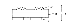
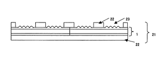
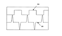
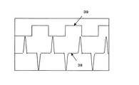
図4も、セキュリティセキュリティスレッド1の構成の一例を示す断面図である。前述の軟磁性体を用いた場合や、硬磁性体でも同じように可能であるが、磁性層3をパターン状に設けた場合の例を示している。
FIG. 4 is also a cross-sectional view showing an example of the configuration of the
図5は、上記のセキュリティスレッド1を紙に漉き込んだ状態のセキュリティ用紙21の一例を示す断面図である。セキュリティスレッド1が漉き込み紙22で挟まれており、反射層4が形成された側の紙の一部に窓開き部23が設けられている状態を示している。
FIG. 5 is a cross-sectional view showing an example of the
図6も、上記のセキュリティスレッド1を紙に漉き込んだ状態のセキュリティ用紙21の一例を示す断面図である。セキュリティスレッド1が漉き込み紙22で挟まれており、ホログラムまたは回折格子4’が形成された側の紙の一部に窓開き部23が設けられている。
FIG. 6 is also a cross-sectional view showing an example of the
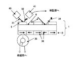
図7は、磁気層3への磁気情報の記録方法の概念を示す説明図である。反射部5への入射光31に対しては、反射光32が得られる。それに対し、非反射部6への入射光33に対しては、非反射部6の反射光34は検出するのに必要な十分な強度得られない。したがって、反射部5への入射光31を図7の左から右に向かって走査すると、反射光あり→なし→あり→なし→ありの情報が得られる。このタイミングで、裏面の磁性層3への磁気記録を磁気ヘッド35を使用して反射あり部を右向きに磁気記録し、反射なし部を左向きに磁気記録すれば、表面の反射光情報と同じ情報を磁気記録することができる。さらには、このような直接の記録ではなく、いくつかの反射光情報をひとまとめにして符号化し、この符号を磁気層3に記録することも可能である。さらには、符号化された反射光情報をさらに任意のアルゴリズムで変換して得られた情報を磁気層3に記録することも可能である。
FIG. 7 is an explanatory diagram showing the concept of a method for recording magnetic information on the
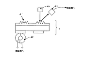
図8は、ホログラムまたは回折格子からの反射光情報と磁気情報の読取方法の概念を示す説明図である。ホログラムまたは回折格子4’の情報を読取るためには、照射部40と受光部41を設置し、ホログラムまたは回折格子からの反射光(回折光)が受光できるようにする。また、裏面には、磁気情報を読取るための磁気読取部42を設置する。磁気読取部42としては磁気ヘッド35や磁気センサが使用できるが、紙に漉き込んだ場合には磁気読取部42とセキュリティスレッド1の距離が比較的長くなるので、より感度の高い磁気センサを用いるのが好ましい。ただし、硬磁性体で磁気記録を行う場合には、磁気センサ内にある永久磁石で記録が消えない程度の保磁力を有する磁性体を使用する必要がある。受光部41、磁気読取部42とも、その出力信号は検証部に送られて検証される。
FIG. 8 is an explanatory diagram showing a concept of a method of reading reflected light information and magnetic information from a hologram or diffraction grating. In order to read information on the hologram or diffraction grating 4 ′, an
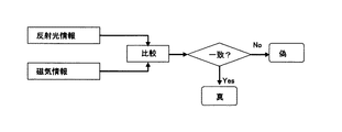
図9は、検証方式の一例を示す説明図である。反射層4から得られた反射光情報と磁性層3から得られた磁気情報を一定のアルゴリズムで比較し、一致するかどうかにより真または偽と判定する。具体的には、反射光情報を反映した信号と磁性層に記録された磁気情報を反映した信号を比較し、両者の位相差がどの程度一定であるかどうか、また両者の周期がどの程度一致しているかどうか、を判定する。磁気情報は元々、反射光情報を磁性層に記録した情報であるが、反射光情報を読み取り、その信号を反映した磁気ヘッドの駆動電流に変換し、磁性層に記録するまでに時間的な遅れが生じるため、元々の信号は、位相が揃っていても、磁性層に記録されるまでには、どうしても位相差が出てくる。しかし、磁気情報が反射光情報を記録した情報である限り、その位相差は一定であり、周期は一致していなければならない。逆に、磁気情報が反射光情報を反映していない情報である場合は、位相差が一定でなく、周期が一致しないため、偽であると判定できる。
FIG. 9 is an explanatory diagram showing an example of the verification method. The reflected light information obtained from the reflective layer 4 and the magnetic information obtained from the
また読取で得られた情報を即時に同時に判定しても、一旦演算を介して比較した後に判定しても差し支えない。アナログ情報のままでも、デジタル情報へ変換してからの判定で
も、差し支えない。また、図6の窓開き部23がホログラムまたは回折格子4’に部分的にかかってしまった場合には、その部分のホログラムまたは回折格子の情報が正確に読取れないが、これも読取アルゴリズムで部分的に一致すれば真と判定するような判定基準を設定することも可能である。
Information obtained by reading may be determined immediately at the same time, or may be determined after being compared once through computation. Even if it is analog information, it can be judged after conversion to digital information. In addition, when the
基材として、25μm厚のPETフィルム、ルミラー25T60(東レ(株)製)を使用した。この表面に、下記蒸着アンカー層インキ組成からなるインキをワイヤーバーにて1μm厚で塗工したあと、アルミニウムを蒸着法にて40nmの厚みで蒸着した。さらに、5mm間隔でマスク用インキ組成からなるインキを2μmの厚みで設けマスク層とした。これを2N水酸化ナトリウム水溶液で10分ほどエッチングし、反射層が得られた。
(蒸着アンカー層インキ組成)
・塩酢ビ樹脂 ソルバインA(日信化学工業(株)製) 20重量部
・イソシアネート硬化剤 デュラネート24A100(旭化成(株)製)
5重量部
・メチルエチルケトン/トルエン 75重量部
(マスク用インキ組成)
・塩酢ビ樹脂 ソルバインA(日信化学工業(株)製) 30重量部
・シクロヘキサノン/イソホロン 70重量部
As a base material, a PET film having a thickness of 25 μm, Lumirror 25T60 (manufactured by Toray Industries, Inc.) was used. On this surface, an ink having the following vapor deposition anchor layer ink composition was applied with a wire bar to a thickness of 1 μm, and then aluminum was vapor deposited by a vapor deposition method to a thickness of 40 nm. Further, an ink composed of a mask ink composition was provided at a thickness of 2 μm at intervals of 5 mm to form a mask layer. This was etched with a 2N aqueous sodium hydroxide solution for about 10 minutes to obtain a reflective layer.
(Vapor deposition anchor layer ink composition)
・ Vinyl chloride resin Solvain A (Nisshin Chemical Industry Co., Ltd.) 20 parts by weight ・ Isocyanate curing agent Duranate 24A100 (Asahi Kasei Co., Ltd.)
5 parts by weight ・ 75 parts by weight of methyl ethyl ketone / toluene (mask ink composition)
・ Vinyl vinyl chloride resin sorbine A (manufactured by Nissin Chemical Industry Co., Ltd.) 30 parts by weight ・ Cyclohexanone / isophorone 70 parts by weight
次に、裏面に下記磁性層インキ組成からなるインキをワイヤーバーにて15μm厚で印刷し、300mTの配向磁場にて磁気配向を行った。これを60℃にて72時間エージングを行って、磁性層3を得た。今回使用した磁性粉の保磁力は約220kA/mであった。また、磁化容易軸方向の角形比は0.85であった。
(磁性層インキ組成)
・バリウムフェライト磁性粉 MC−127(戸田工業(株)製) 25重量部
・塩酢ビ樹脂 ソルバインA(日信化学工業(株)製) 10重量部
・メチルエチルケトン/トルエン 65重量部
・イソシアネート硬化剤デュラネート24A100(旭化成(株)製)
5重量部
Next, the ink which consists of the following magnetic layer ink composition was printed on the back surface with the thickness of 15 micrometers with the wire bar, and the magnetic orientation was performed by the orientation magnetic field of 300 mT. This was aged at 60 ° C. for 72 hours to obtain the
(Magnetic layer ink composition)
・ Barium ferrite magnetic powder MC-127 (manufactured by Toda Kogyo Co., Ltd.) 25 parts by weight ・ Vinyl vinyl chloride resin sorbine A (manufactured by Nissin Chemical Industry Co., Ltd.) 10 parts by weight ・ Methyl ethyl ketone / toluene 65 parts by weight ・ Isocyanate curing agent Duranate 24A100 (Asahi Kasei Corporation)
5 parts by weight
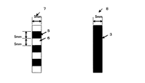
このようにして得た原反から磁化容易軸方向を長手方向にとり、5mm幅にスリットしてセキュリティスレッドを切り出した。このセキュリティスレッドの表裏の様子を図10に示す。反射層は5mm間隔で設けられている。まず、磁性層全体を、図7で示す左矢印の方向に磁気記録を行った。次に、反射層に635nmの半導体レーザーを照射し、その正反射をフォトディテクタで受け、その出力をスイッチとして磁気ヘッドに記録電流を流し、裏面の磁性層にフォトディテクタに光が入射した時のみ、図7の右矢印方向に磁気記録を行い、図7と同様の磁気記録が施されたセキュリティスレッドを得た。
From the raw material thus obtained, the easy axis of magnetization was taken as the longitudinal direction, and the security thread was cut out by slitting to a width of 5 mm. The front and back of this security thread is shown in FIG. The reflective layers are provided at intervals of 5 mm. First, magnetic recording was performed on the entire magnetic layer in the direction of the left arrow shown in FIG. Next, the reflection layer is irradiated with a 635 nm semiconductor laser, the specular reflection is received by a photodetector, a recording current is passed through the magnetic head using the output as a switch, and light is incident on the photodetector on the back magnetic layer. Magnetic recording was performed in the direction of the
このセキュリティスレッドを用い、窓開き部の大きさが幅10mm、高さ30mmになるようにして手漉きで抄紙し、十分に脱水・乾燥させてセキュリティ用紙を得た。最終的なセキュリティ用紙の大きさは、15cm×5cmとした。なお、表裏の情報の読取易さのため、セキュリティスレッドはセキュリティ用紙の長手方向にとった。 Using this security thread, paper was made by hand so that the size of the window opening was 10 mm wide and 30 mm high, and was sufficiently dehydrated and dried to obtain a security paper. The final security paper size was 15 cm × 5 cm. For ease of reading the information on the front and back, the security thread was taken in the longitudinal direction of the security paper.
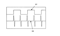
反射層の読取は、635nmの半導体レーザーを照射し、その正反射方向にフォトディテクタをおいて、その出力にオシロスコープを接続した。磁性層の読取は、セキュリティ用紙の裏面方向に磁気抵抗センサMR−F−21(ニッコーシ(株)製)を置き、OPアンプで1000倍に増幅した出力を同じくオシロスコープに接続した。 Reading of the reflective layer was performed by irradiating a 635 nm semiconductor laser, placing a photodetector in the regular reflection direction, and connecting an oscilloscope to the output. For reading the magnetic layer, a magnetoresistive sensor MR-F-21 (manufactured by Nikkoshi Co., Ltd.) was placed on the back side of the security paper, and the output amplified 1000 times with an OP amplifier was connected to an oscilloscope.
それぞれの出力波形を図12に示す。この出力から、間隔が等しく、タイミングの合っ
た二つの波形が得られた。この波形を取り込んで真偽判定することは可能であると考えられる。
Each output waveform is shown in FIG. From this output, two waveforms were obtained that were equally spaced and timed. It is considered possible to determine the authenticity by taking in this waveform.
(比較例1)
磁性層に磁気記録を行わなかった以外は、実施例と同様に作成し、オシロスコープで測定した結果を図13に示す。この場合は、磁性層の磁力線の変化がないため、出力が得られない。出力がないため、明らかに偽と判断できる。
(Comparative Example 1)
FIG. 13 shows the result of the measurement made with the oscilloscope except that no magnetic recording was performed on the magnetic layer. In this case, no output is obtained because there is no change in the magnetic field lines of the magnetic layer. Since there is no output, it can be clearly judged as false.
基材として、25μm厚のPETフィルム、ルミラー25T60(東レ(株)製)を使用した。この表面に、下記回折格子層インキ組成からなるインキをワイヤーバーにて2μm厚で塗工したあと、アルミニウムを蒸着法にて40nmの厚みで蒸着した。さらに、5mm間隔で設けた格子間隔1μmの回折格子のパターンを形成したスタンパーを用いて、アルミニウムの蒸着層上に回折格子のパターンを形成した。これを60℃にて72時間エージングを行い、回折格子層インキを硬化した。さらにこの上に、回折格子層インキ組成と同一組成のインキを1μmの厚みで設け、60℃にて72時間エージングを行い、保護層とした。
以上で、回折格子が得られた。
(回折格子層インキ組成)
・アクリルポリオール樹脂 MCA4039(DIC(株)製) 30重量部
・イソシアネート硬化剤 デュラネート24A100(旭化成(株)製)
10重量部
・メチルエチルケトン/トルエン 60重量部
As a base material, a PET film having a thickness of 25 μm, Lumirror 25T60 (manufactured by Toray Industries, Inc.) was used. On this surface, an ink composed of the following diffraction grating layer ink composition was coated with a wire bar to a thickness of 2 μm, and then aluminum was deposited to a thickness of 40 nm by a vapor deposition method. Further, a diffraction grating pattern was formed on the aluminum deposition layer by using a stamper having a diffraction grating pattern of 1 μm with a grating interval of 5 mm. This was aged at 60 ° C. for 72 hours to cure the diffraction grating layer ink. Further thereon, an ink having the same composition as the diffraction grating layer ink composition was provided in a thickness of 1 μm and aged at 60 ° C. for 72 hours to form a protective layer.
Thus, a diffraction grating was obtained.
(Diffraction grating layer ink composition)
・ Acrylic polyol resin MCA4039 (manufactured by DIC Corporation) 30 parts by weight ・ Isocyanate curing agent Duranate 24A100 (manufactured by Asahi Kasei Corporation)
10 parts by weight ・ Methyl ethyl ketone / toluene 60 parts by weight
次に、裏面に下記磁性層インキ組成からなるインキをスクリーン印刷法にて3μm厚で5mm間隔にてパターン印刷し、60℃にて72時間エージングを行って、磁性層を得た。今回使用した磁性粉の保磁力は約10kA/mであった。
(磁性層インキ組成)
・マグネタイト磁性粉MG−7000(三井金属鉱業(株)製) 15重量部
・ウレタン系スクリーンインキメジウムSS16
(東洋インキ製造(株)製) 70重量部
・イソシアネート硬化剤デュラネート24A100(旭化成(株)製)
15重量部
Next, an ink having the following magnetic layer ink composition was printed on the back surface by a screen printing method at a pattern thickness of 3 μm at intervals of 5 mm and aged at 60 ° C. for 72 hours to obtain a magnetic layer. The coercive force of the magnetic powder used this time was about 10 kA / m.
(Magnetic layer ink composition)
・ Magnetite magnetic powder MG-7000 (Mitsui Metal Mining Co., Ltd.) 15 parts by weight ・ Urethane-based screen ink medium SS16
(Toyo Ink Manufacturing Co., Ltd.) 70 parts by weight ・ Isocyanate curing agent Duranate 24A100 (Asahi Kasei Co., Ltd.)
15 parts by weight
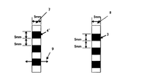
このようにして得た原反から5mm幅にスリットしてセキュリティスレッドを切り出した。このセキュリティスレッドの表裏の様子を図11に示す。表面の回折格子は回折光が幅方向に得られるようになっている。回折格子、磁性層とも5mm間隔で設けられている。このセキュリティスレッドを用い、窓開き部の大きさが幅10mm、高さ30mmになるようにして手漉きで抄紙し、十分に脱水・乾燥させてセキュリティ用紙を得た。最終的なセキュリティ用紙の大きさは、15cm×5cmとした。なお、表裏の情報の読取易さのため、セキュリティスレッド1はセキュリティ用紙の長手方向にとった。
A security thread was cut out from the raw material thus obtained by slitting to a width of 5 mm. The state of the front and back of this security thread is shown in FIG. The diffraction grating on the surface can obtain diffracted light in the width direction. Both the diffraction grating and the magnetic layer are provided at intervals of 5 mm. Using this security thread, paper was made by hand so that the size of the window opening was 10 mm wide and 30 mm high, and was sufficiently dehydrated and dried to obtain a security paper. The final security paper size was 15 cm × 5 cm. Note that the
回折格子の読取は、635nmの半導体レーザーを法線方向から照射し、法線から40度の方向にフォトディテクタをおいて、その出力にオシロスコープを接続した。磁性層の読取は、セキュリティ用紙の裏面方向に磁気抵抗センサMR−F−21(ニッコーシ(株)製)を置き、OPアンプで千倍に増幅した出力を同じくオシロスコープに接続した。 Reading of the diffraction grating was performed by irradiating a semiconductor laser of 635 nm from the normal direction, placing a photodetector at a direction of 40 degrees from the normal, and connecting an oscilloscope to the output. For reading the magnetic layer, a magnetoresistive sensor MR-F-21 (manufactured by Nikkoshi Co., Ltd.) was placed on the back side of the security paper, and the output amplified 1000 times with an OP amplifier was also connected to an oscilloscope.
それぞれの出力波形を図14に示す。これらの出力波形から、2つの信号の位相はずれているが、周期は一致していると判断できるので、この波形を取り込んで真偽判定することは可能であると考えられる。 Each output waveform is shown in FIG. Although it can be determined from these output waveforms that the phases of the two signals are out of phase but the periods are the same, it is considered that this waveform can be taken in and the authenticity can be determined.
(比較例2)
磁性層の間隔を3mm間隔にした以外は実施例と同様に作成し、オシロスコープで測定した結果を図15に示す。この場合は、2つの信号の位相も周期も不一致であるため、偽と判断できる。
(比較例3)
磁性層を設けなかった以外は、実施例2と同様に作製し、オシロスコープで測定した結果を図16に示す。この場合は、磁性層の出力がないため、明らかに偽と判断できる
(Comparative Example 2)
FIG. 15 shows the result of measurement similar to that of the example except that the interval between the magnetic layers was changed to 3 mm and measured with an oscilloscope. In this case, since the phase and the period of the two signals are inconsistent, it can be determined to be false.
(Comparative Example 3)
FIG. 16 shows the result of manufacturing in the same manner as in Example 2 and measuring with an oscilloscope except that the magnetic layer was not provided. In this case, since there is no output of the magnetic layer, it can be clearly judged as false.
1…セキュリティスレッド
2…基材
3…磁性層
4…反射層
4’…ホログラムまたは回折格子
5…反射部
6…非反射部
7…セキュリティスレッドの表面
8…セキュリティスレッドの裏面
9…回折方向
11…蒸着アンカー層
12…金属蒸着層
13…マスク層
21…セキュリティ用紙
22…漉き込み紙
23…窓開き部
31…反射部への入射光
32…反射部からの反射光
33…非反射部への入射光
34…非反射部からの反射光(存在しない)
35…磁気ヘッド
36…磁気情報
37…反射層からの反射光情報の波形
38…磁気情報の波形
39…ホログラムまたは回折格子からの反射光情報の波形
40…照射部
41…受光部
42…磁気読取部
DESCRIPTION OF
35 ...
Claims (7)
Priority Applications (1)
| Application Number | Priority Date | Filing Date | Title |
|---|---|---|---|
| JP2009281579A JP2011123722A (en) | 2009-12-11 | 2009-12-11 | Security thread, security paper sheet and verification method |
Applications Claiming Priority (1)
| Application Number | Priority Date | Filing Date | Title |
|---|---|---|---|
| JP2009281579A JP2011123722A (en) | 2009-12-11 | 2009-12-11 | Security thread, security paper sheet and verification method |
Publications (1)
| Publication Number | Publication Date |
|---|---|
| JP2011123722A true JP2011123722A (en) | 2011-06-23 |
Family
ID=44287543
Family Applications (1)
| Application Number | Title | Priority Date | Filing Date |
|---|---|---|---|
| JP2009281579A Pending JP2011123722A (en) | 2009-12-11 | 2009-12-11 | Security thread, security paper sheet and verification method |
Country Status (1)
| Country | Link |
|---|---|
| JP (1) | JP2011123722A (en) |
Cited By (7)
| Publication number | Priority date | Publication date | Assignee | Title |
|---|---|---|---|---|
| JP2016000886A (en) * | 2015-09-25 | 2016-01-07 | 凸版印刷株式会社 | Anti-counterfeit paper |
| KR101785467B1 (en) * | 2016-01-19 | 2017-10-17 | 한국조폐공사 | Dual color-shifting security element and method for producing it, security product comprising it |
| CN108604397A (en) * | 2016-03-29 | 2018-09-28 | 光荣株式会社 | Paper representing value processing unit and paper representing value processing method |
| WO2019116724A1 (en) * | 2017-12-12 | 2019-06-20 | 日本電気株式会社 | Automatic teller machine, terminal device, and medium reading method |
| WO2022063570A1 (en) * | 2020-09-25 | 2022-03-31 | Leonhard Kurz Stiftung & Co. Kg | Multilayer body and method for producing a multilayer body |
| KR20230013586A (en) * | 2021-07-19 | 2023-01-26 | 최이진 | Security document printing method and apparatus that can identify the authenticity of security paper |
| JP7496744B2 (en) | 2020-09-08 | 2024-06-07 | グローリー株式会社 | Paper sheet identification device, paper sheet processing device, and paper sheet identification method |
-
2009
- 2009-12-11 JP JP2009281579A patent/JP2011123722A/en active Pending
Cited By (9)
| Publication number | Priority date | Publication date | Assignee | Title |
|---|---|---|---|---|
| JP2016000886A (en) * | 2015-09-25 | 2016-01-07 | 凸版印刷株式会社 | Anti-counterfeit paper |
| KR101785467B1 (en) * | 2016-01-19 | 2017-10-17 | 한국조폐공사 | Dual color-shifting security element and method for producing it, security product comprising it |
| CN108604397A (en) * | 2016-03-29 | 2018-09-28 | 光荣株式会社 | Paper representing value processing unit and paper representing value processing method |
| WO2019116724A1 (en) * | 2017-12-12 | 2019-06-20 | 日本電気株式会社 | Automatic teller machine, terminal device, and medium reading method |
| US11373487B2 (en) | 2017-12-12 | 2022-06-28 | Nec Corporation | Automatic teller machine, terminal device, and medium reading method |
| JP7496744B2 (en) | 2020-09-08 | 2024-06-07 | グローリー株式会社 | Paper sheet identification device, paper sheet processing device, and paper sheet identification method |
| WO2022063570A1 (en) * | 2020-09-25 | 2022-03-31 | Leonhard Kurz Stiftung & Co. Kg | Multilayer body and method for producing a multilayer body |
| KR20230013586A (en) * | 2021-07-19 | 2023-01-26 | 최이진 | Security document printing method and apparatus that can identify the authenticity of security paper |
| KR102561580B1 (en) | 2021-07-19 | 2023-07-28 | 최이진 | Security document printing method and apparatus that can identify the authenticity of security paper |
Similar Documents
| Publication | Publication Date | Title |
|---|---|---|
| JP2011123722A (en) | Security thread, security paper sheet and verification method | |
| US6502757B1 (en) | Information recorded medium, device for reading the information, information recorded medium transfer foil, and method for producing information recorded medium | |
| KR20170122888A (en) | Reflect-type film for preventing counterfeit | |
| JPH10105031A (en) | Information recording medium | |
| JP2000033789A (en) | Magnetic transfer sheet with OVD image | |
| JPH0146923B2 (en) | ||
| JP3964536B2 (en) | Information recording medium | |
| JPH0250528B2 (en) | ||
| JP4071305B2 (en) | Method for producing magnetically patterned magnetic plate | |
| JP4627767B2 (en) | Information recording medium | |
| GB2318089A (en) | Banknote with two magnetic security features | |
| JPH07214955A (en) | Card-shaped article to be detected checked in genuineness and production thereof | |
| Coombs et al. | Overt and covert verification via magnetic optical security devices | |
| JP2706714B2 (en) | Magnetic recording medium and manufacturing method thereof | |
| JP2736852B2 (en) | Magnetic recording medium and method of manufacturing the same | |
| JP4034605B2 (en) | Anti-counterfeit thread, anti-counterfeit paper using the same, and authenticity determination method | |
| JPH0418869Y2 (en) | ||
| JP3192633B2 (en) | Magnetic recording medium and method for reproducing fixed information from magnetic recording medium | |
| JPH0899484A (en) | Card and its authenticity determination method | |
| JPH04274021A (en) | Magnetic recording medium | |
| JP2004227123A (en) | Magnetic recording medium and method of determining authenticity | |
| JP3949141B2 (en) | Certification media | |
| KR0185982B1 (en) | Anti-modulation device of magnetic card | |
| JP2613854B2 (en) | Composite magnetic recording media | |
| JP5636750B2 (en) | Thread and anti-counterfeit paper |