JP2007213094A - Information storage medium - Google Patents
Information storage medium Download PDFInfo
- Publication number
- JP2007213094A JP2007213094A JP2007110292A JP2007110292A JP2007213094A JP 2007213094 A JP2007213094 A JP 2007213094A JP 2007110292 A JP2007110292 A JP 2007110292A JP 2007110292 A JP2007110292 A JP 2007110292A JP 2007213094 A JP2007213094 A JP 2007213094A
- Authority
- JP
- Japan
- Prior art keywords
- hologram
- magnetic
- pattern
- recording medium
- information recording
- Prior art date
- Legal status (The legal status is an assumption and is not a legal conclusion. Google has not performed a legal analysis and makes no representation as to the accuracy of the status listed.)
- Granted
Links
Images


Abstract
Description
本発明は、プリペイドカード・金券・債券・プログラムソフトのパッケージ等の高付加価値商品を、偽造防止のための管理情報を付加して実現することができる情報記録媒体に関するものである。 The present invention relates to an information recording medium capable of realizing high value-added products such as prepaid cards, cash vouchers, bonds, and program software packages by adding management information for preventing forgery.
記録媒体カードとしては(1)プリペイドカードや(2)キャシュカードが用いられている。(1)の例としてはNTT(日本電信電話株式会社)の発行するテレホンカードや日本カードシステムの発行するパチンコ遊技カードあるいは交通機関の発行する定期・切符・プリペイドカードなどがある。(2)の例としては銀行のキャッシュカードや信販会社のクレジットカードがある。これらが真正品であるかどうかは、カードに内蔵されていた磁気データを読み取り照合するか、またはカードに貼られた顔写真やホログラム等で真正品であるかどうか判定している。さらに、製造年月日または利用度数や暗証番号など製造・利用上の種々の管理情報をカード内に磁気データとして記録し、書き換えを行なっている。また、(3)商品券、ビール券などの金券類、(4)株式や公債などの証券類においても、偽造防止を目的に高度な印刷技術やホログラムなどを利用し、管理情報の書き込みにはバーコードなどを利用している。さらに、最近では、(5)コンピュータ用のプログラムソフトなどにも、それが真正品の証としてホログラムなどが利用されている。 As the recording medium card, (1) a prepaid card or (2) a cash card is used. Examples of (1) include a telephone card issued by NTT (Nippon Telegraph and Telephone Corporation), a pachinko game card issued by the Nippon Card System, or a periodic / ticket / prepaid card issued by a transportation facility. Examples of (2) include bank cash cards and credit card companies. Whether or not these are genuine products is determined by reading or collating magnetic data stored in the card, or by determining whether the product is a genuine product by using a face photograph or hologram attached to the card. Furthermore, various management information on manufacture and use such as date of manufacture, frequency of use, and personal identification number is recorded as magnetic data in the card and rewritten. In addition, (3) gift certificates such as gift certificates and beer coupons, and (4) securities such as stocks and public bonds use advanced printing technology and holograms to prevent counterfeiting and write management information. Bar code etc. are used. Further, recently, (5) holograms and the like have been used in computer program software as a proof of authenticity.
上記の高付加価値商品は変造・改ざんされ易く大きな社会問題となっている。これらのうちカード類((1)〜(2))については変造・改ざん防止対策として平成5年3月31日提出の特願平5−094846号「記録担体カードとその真偽判定装置」(出願人:岩崎通信機(株))が提案されている。この従来技術1では、記録担体カードは従来からある第一の磁気記録領域と、アモルファス強磁性体層からなる第二の記録領域とを備え、この第二の記録領域にはセキュリティコードを記録し、かつ、度数等を表示するパンチ穴を磁気的に検出できる構造を有している。従って、パンチ穴を隠す遮蔽材による改ざんを容易に検出できる優れた利点を有し、さらに前記第二の記録領域に設けたセキュリティコードは書換・消去が不可能で、常にそのコードを参照し真偽を判定できることになる。
The above high-value-added products are easily altered or tampered with and become a big social problem. Of these, the cards ((1) to (2)) are filed on March 31, 1993 as a measure for preventing falsification and falsification, Japanese Patent Application No. 5-094846, “Recording Card and its Authenticity Determination Device” ( (Applicant: Iwasaki Tsushinki Co., Ltd.) has been proposed. In this
また、情報記録媒体としてアモルファス強磁性薄膜とホログラムを組み合わせた平成8年9月30日提出の特願平8−276878号「情報記録媒体」(出願人:岩崎通信機(株))が提案されている。この従来技術2は、ホログラムとアモルファス強磁性材とを備えることで、ホログラムが本来持つ機能に加え、アモルファスに記録された情報を磁気的に読み取ることができる。
Also, Japanese Patent Application No. 8-276878 “Information Recording Medium” (Applicant: Iwasaki Tsushinki Co., Ltd.) filed on September 30, 1996, which combined an amorphous ferromagnetic thin film and a hologram as an information recording medium, was proposed. ing. By providing the hologram and the amorphous ferromagnetic material, the
さらに、これらの磁性体に対し簡単に信号を付加する方法として、平成8年8月14日提出の特願平8−231288号「磁気パターンニングされた磁性体板とその製造方法」(出願人:岩崎通信機(株))が提案されている。この従来技術3では、平坦な基板上にインクの塗布または科学的・物理的手法により凹凸を設け、平坦な領域と凹凸を設けた領域とで磁気特性を変化させ、その違いにより記録した情報を磁気的に読みとることができるようにしている。
一方、ホログラムは例えばミクロオーダの凹凸(回折格子)をフィルム表面に設け、この上に金属薄膜を形成し、立体映像や干渉色などその特徴的な模様を再生し偽造防止に利用している。このとき用いる金属は光を適度に反射すればよく、安価なアルミニウムなどが用いられ、磁性金属は一般に用いられていない。このミクロンオーダの凹凸を作製するには非常に高度な技術を要し簡単には偽造できないが、近年では偽造されるケースも生じてきた。 On the other hand, for example, a micro-order unevenness (diffraction grating) is provided on the surface of a hologram, and a metal thin film is formed on the hologram to reproduce a characteristic pattern such as a three-dimensional image or an interference color to prevent forgery. The metal used at this time only needs to reflect light moderately, inexpensive aluminum or the like is used, and magnetic metal is not generally used. Producing such micron-order irregularities requires a very advanced technique and cannot be easily counterfeited, but in recent years there have been cases of forgery.
磁気データを書き込む手法として前記の従来技術2(特願平8−276878号「情報記録媒体」)では材質の異なる磁性体を用いるか、または磁性体の有無によって情報を記録するようにしていた。従って、磁性材にはアモルファスを用い、かつホログラムとは別に磁性体に信号を書き込む必要があった。 As a technique for writing magnetic data, the above-described conventional technique 2 (Japanese Patent Application No. 8-276878, “Information Recording Medium”) uses magnetic materials of different materials or records information depending on the presence or absence of magnetic materials. Therefore, it is necessary to use an amorphous magnetic material and write a signal to the magnetic material separately from the hologram.
本発明の目的は、従来のプリペイドカードやキャシュカードさらには金券類などの高付加価値商品が比較的容易に偽造・変造できるという欠点を排除し、カードだけでなく種々の高付加価値商品に転写あるいは貼り付けで簡単に付加できる偽造防止機能を有する情報記録媒体を提供することにある。 The object of the present invention is to eliminate the disadvantage that high-value-added products such as conventional prepaid cards, cash cards and cash vouchers can be forged and altered relatively easily, and transfer them to various high-value-added products as well as cards. Another object is to provide an information recording medium having a forgery prevention function that can be easily added by pasting.
この目的を達成するために、本発明による情報記録媒体は、基材と、該基材の表面上に規則的または不規則的に設けた回折格子の凹凸が該回折格子の凹凸からの反射光でホログラムパターンとして観測されるように形成されたホログラム領域と、該ホログラム領域の上にアモルファス強磁性材料で形成された強磁性体薄膜とを備え、偽造防止のための管理情報として該強磁性体薄膜に該ホログラムパターンまたは該ホログラム領域の形状パターンに応じた特徴的な磁気特性を保持させたことを特徴とする構成を有している。 In order to achieve this object, an information recording medium according to the present invention includes a base material, and irregularities of a diffraction grating regularly or irregularly provided on the surface of the base material. And a ferromagnetic thin film formed of an amorphous ferromagnetic material on the hologram region, and the ferromagnetic material is used as management information for preventing counterfeiting. The thin film has a configuration in which characteristic magnetic characteristics corresponding to the hologram pattern or the shape pattern of the hologram region are held.
以上詳細に説明したように、本発明によるホログラム領域と磁性体を組み合わせることでセキュリティ性の高い情報記録媒体が得られ、磁気的に信号を読み取り真偽判定を行なうことができ、かつ、目視による画像認識あるいは機械読み取りといった光学的にも真偽判定することができる。さらには、必要に応じてホログラムで磁気信号を付加することも可能である。 As described above in detail, the information recording medium with high security can be obtained by combining the hologram region and the magnetic material according to the present invention, the signal can be read magnetically, the authenticity can be determined, and the visual inspection can be performed. The authenticity can be determined optically such as image recognition or machine reading. Furthermore, it is also possible to add a magnetic signal with a hologram as required.
本発明は、光学的に真偽判定するホログラムと磁気的に信号読み取り及び真偽判定する磁性体膜とからなり、磁性体膜はホログラムの回折格子上に直接又は非磁性金属膜を介在させて形成されている。本発明で利用する磁性体は基本的には蒸着またはスパッタ等の気相成長による薄膜であるため、その磁気特性は表面状態、特に表面の凹凸に大きく左右される。強磁性体薄膜は、回折格子の凹凸の表面に沿って同様の凹凸形状に反射層として形成されており、場合により、基材と強磁性体薄膜の間又は強磁性体薄膜の次に、光の反射層として非磁性金属膜をさらに形成してもよい。このようにした場合には、強磁性体薄膜の色に影響されることなしに、非磁性金属の光沢色が反射光として外部から観測されるようになり、外見上は一般的なホログラムと変わらない情報記録媒体が与えられる。基材としては、通常樹脂フィルムが用いられるが、その表面上にホログラムパターンを形成することができ、種々の媒体に貼り付け・転写・挿入などで付加することができれば、金属・ガラス等の如き他の材料を用いることができる。なお、本発明で用いる強磁性体薄膜の材料としては、軟磁性材料,硬磁性材料を用いることができ、また、結晶性強磁性材料に限らずアモルファス(非結晶性)強磁性材料を用いることができる。さらに、本発明の情報記録媒体を種々の対象物体に貼付け・転写するときには、基板に透明な樹脂フィルム・ガラスなどを用いれば、強磁性体薄膜側を下に基材側を上にし、基材をホログラムの保護層として利用することができる。また、基材側を下に強磁性体薄膜を上にして、種々の対象
物に貼付け・転写するときには、透明な樹脂保護層を強磁性体層の上にさらに設けた方がよい。一般には、平坦な基板上に一方向に傷(スクラッチ)を入れるかあるいは、パターンニングによって微細な長方形に加工すると、形状磁気異方性が生じ、その傷あるいはパターンに沿って磁化容易軸を持つということが知られている。前述の従来技術3「磁気パターンニングされた磁性体板とその製造方法」(特願平8−231288号)では平坦な基板上にインクの塗布または化学的・物理的手法により凹凸を設け、平坦な領域と凹凸を設けた領域とで磁気特性を変化させ、その違いにより記録した情報を磁気的に読み取るとしていた。これに対し、本発明では例えば樹脂等の基材の表面にミクロン(μm)オーダの凹凸を規則的又は不規則的に設けた回折格子からの反射光でホログラムパターンとして観測されるように形成されたホログラム領域を含ませ、このホログラム領域の上に強磁性体の薄膜を形成することで、この磁性膜にホログラムパターンまたはホログラム領域の形状パターンに応じた特徴的な磁気特性を保持させている。なお、磁気特性の変化とは具体的には保持力、飽和磁束密度、角形比などの変化である。本発明による情報記録媒体の磁気特性は、本来の磁性材料が持つ磁気特性とホログラムパターンの形状効果との組合せによって特徴づけられている。
The present invention comprises a hologram for optical authenticity determination and a magnetic film for magnetic signal reading and authenticity, and the magnetic film is formed directly on the diffraction grating of the hologram or with a nonmagnetic metal film interposed. Is formed. Since the magnetic material used in the present invention is basically a thin film formed by vapor phase growth such as vapor deposition or sputtering, the magnetic properties are greatly influenced by the surface state, particularly the surface irregularities. The ferromagnetic thin film is formed as a reflective layer in the same concave-convex shape along the concave-convex surface of the diffraction grating, and in some cases, light is applied between the substrate and the ferromagnetic thin film or next to the ferromagnetic thin film. A nonmagnetic metal film may be further formed as the reflective layer. In this case, the glossy color of the non-magnetic metal can be observed as reflected light from the outside without being affected by the color of the ferromagnetic thin film. No information recording medium is given. As the base material, a resin film is usually used. However, if a hologram pattern can be formed on the surface and can be added to various media by pasting, transferring, inserting, etc., such as metal, glass, etc. Other materials can be used. In addition, as a material of the ferromagnetic thin film used in the present invention, a soft magnetic material and a hard magnetic material can be used, and not only a crystalline ferromagnetic material but also an amorphous (non-crystalline) ferromagnetic material should be used. Can do. Furthermore, when the information recording medium of the present invention is pasted and transferred to various target objects, if a transparent resin film, glass, or the like is used for the substrate, the ferromagnetic thin film side is turned down and the substrate side is turned up. Can be used as a hologram protective layer. Further, when affixing / transferring on various objects with the ferromagnetic thin film facing up, it is preferable to further provide a transparent resin protective layer on the ferromagnetic layer. In general, when scratches are scratched in one direction on a flat substrate or processed into a fine rectangle by patterning, shape magnetic anisotropy occurs, and there is an easy magnetization axis along the scratches or pattern. It is known that. In the above-mentioned
第1番目の形態は、樹脂フィルムを基材とし、その表面に規則的に凹凸を設けた回折格子からなるホログラム領域が存在し、ホログラム領域は全面がひとつの決まった規則で回折格子が配列され、この回折格子上に強磁性体薄膜が直接形成されている。これを所定の形状に切り抜き、紙やプラスチックでできている高付加価値商品に接着で貼り付けるかまたは挿入することでその高付加価値商品の偽造を防止することができる。挿入など高付加価値商品の中に埋め込む場合には、磁気的に読み取れるように情報記録媒体を表面近傍に埋め込むか、あるいは光学的にホログラムを確認したい場合には磁気ホログラム情報記録媒体の少なくとも一部を表面に露出させる必要がある。また、ホログラムを形成する基材を薄くして、より厚い基材に予め貼り合わせておき、磁性体を成膜した後に接着層を設けておけば、任意の形状にホログラムを転写で貼り付けることができる。 In the first form, there is a hologram region composed of a diffraction grating having a resin film as a base material and regularly provided with irregularities on the surface thereof, and the entire diffraction region of the hologram region is arranged according to a predetermined rule. A ferromagnetic thin film is directly formed on the diffraction grating. This is cut into a predetermined shape, and forged or attached to a high value-added product made of paper or plastic, it is possible to prevent forgery of the high value-added product. When embedding in a high value-added product such as an insertion, embed the information recording medium near the surface so that it can be magnetically read, or at least part of the magnetic hologram information recording medium if you want to optically check the hologram Must be exposed on the surface. Also, if the base material on which the hologram is to be formed is thinned and pasted on a thicker base material in advance, and an adhesive layer is provided after the magnetic material is deposited, the hologram can be pasted in an arbitrary shape by transfer Can do.
この第1番目の形態ではホログラム領域が情報記録媒体の全面もしくは一部に形成されている。例えば、ホログラムパターンを情報記録媒体の全面もしくは一部に形成するとき、ホログラムの回折格子と読み取り励磁の磁束の向きが平行になるように一様に配置した場合において、その上に直接強磁性材料を形成したときに、全ホログラム領域で磁化容易軸が強く配向し、PET(ポリエステル)フィルムや鏡面非磁性金属板などの平坦な表面に強磁性材料を形成した場合と異なる磁気特性を示す。また、ホログラム領域内をいくつかに分割し、分割された各領域で回折格子の向きを変化させ異方性がなくなるように配置し、その上に強磁性材料を形成すると、面内磁気異方性がなくなり、どの方向から読み取っても同じ磁気特性を示す情報記録媒体が得られる。この情報記録媒体は磁気的に信号を読み取り、その磁気特性から真偽判定を行なうことができ、かつ、目視によりホログラムを確認することで光学的にも真偽判定ができるようになる。 In the first embodiment, the hologram area is formed on the entire surface or a part of the information recording medium. For example, when a hologram pattern is formed on the entire surface or a part of an information recording medium, when the hologram diffraction grating and the magnetic flux for reading excitation are arranged in parallel so as to be parallel to each other, the ferromagnetic material is directly formed on the hologram pattern. When the film is formed, the easy magnetization axis is strongly oriented in the entire hologram region, and magnetic characteristics different from those obtained when a ferromagnetic material is formed on a flat surface such as a PET (polyester) film or a mirrored nonmagnetic metal plate are exhibited. In addition, when the hologram area is divided into several parts, the orientation of the diffraction grating is changed in each of the divided areas so as to eliminate anisotropy, and a ferromagnetic material is formed thereon, the in-plane magnetic anisotropy Thus, an information recording medium showing the same magnetic characteristics can be obtained regardless of the direction of reading. This information recording medium can read a signal magnetically and determine authenticity from its magnetic characteristics, and can also make an authenticity determination optically by visually confirming the hologram.
次に、第2番目の形態は、樹脂フィルムを基材としその表面に規則的に回折格子の凹凸を設けたホログラム領域が存在する有り区域とホログラム領域が無い無し区域が存在し、ホログラム領域では全面がひとつの決まった規則で回折格子が配列され、これらのホログラム領域が存在する有り区域と存在しない無し区域の両方の表面上に強磁性体薄膜が直接形成されている。こうすることで、ホログラム領0の有無に応じた2種類の磁気特性を情報記録媒体に保持させ、この磁気特性の違いを利用しデータを書き込むことができる。高付加価値商品へは、第1番目の形態の場合と同様に、貼り付け・挿入・転写により、付加することができる。
Next, in the second form, there is a zone where there is a hologram region in which a resin film is used as a base material and irregularities of the diffraction grating are regularly provided on the surface, and a zone where there is no hologram region. The diffraction gratings are arranged on the entire surface in accordance with one fixed rule, and a ferromagnetic thin film is directly formed on the surfaces of both the existence area where these hologram areas exist and the absence area where these hologram areas do not exist. In this way, two types of magnetic characteristics corresponding to the presence or absence of the
この第2番目の形態では情報記録媒体にホログラム領域の有無に対応する有り区域と無し区域が所定の規則に則り設けてある。ホログラム領域の有無によって磁気信号を変化さ
せ、これをデータして利用する。例えば、強磁性材料を用いホログラムの回折格子と読み取り励磁の磁束の向きが平行になるようにホログラム領域を配置した場合、ホログラム領域では磁化容易軸が強く配向し、ホログラム領域の有無で磁気特性が変化し、これを読み分け、信号を付与することができる。この情報記録媒体は磁気的に信号を読み取り、その磁気特性から真偽判定を行なうことができ、かつ、目視によりホログラムパターンを確認することで光学的にも真偽判定ができるようになり、さらには製造年月日または暗証番号など製造・利用上の種々の管理情報を高付加価値商品に磁気データとして記録できるようになる。
In the second form, the presence area and the absence area corresponding to the presence or absence of the hologram area on the information recording medium are provided according to a predetermined rule. The magnetic signal is changed depending on the presence or absence of the hologram area, and this is used as data. For example, when a hologram region is arranged using a ferromagnetic material so that the direction of the magnetic flux of reading excitation and the hologram diffraction grating is parallel, the easy magnetization axis is strongly oriented in the hologram region, and the magnetic characteristics are exhibited by the presence or absence of the hologram region. Change, read this, and give a signal. This information recording medium can read a signal magnetically, determine authenticity from its magnetic characteristics, and can optically determine authenticity by visually confirming the hologram pattern. Will be able to record various management information such as date of manufacture or personal identification number as magnetic data on high value-added products.
さらに、第3番目の形態は、例えば回折格子の角度を変えるなどして少なくとも2種類以上の互いにパターンの異なるホログラム領域を存在させ、これらの上に軟磁性体の薄膜が直接形成されている。こうすることで、ホログラムのパターンに応じた2種類以上の磁気特性を情報記録媒体に保持させ、この磁気特性の違いを利用しデータを書き込むことができる。高付加価値商品へは、第1番目の形態の場合と同様に、貼りつけ・挿入・転写により、付加することができる。 Further, in the third embodiment, at least two types of hologram regions having different patterns exist by changing the angle of the diffraction grating, for example, and a soft magnetic thin film is directly formed thereon. In this way, two or more types of magnetic characteristics corresponding to the hologram pattern can be held in the information recording medium, and data can be written using this difference in magnetic characteristics. As in the case of the first form, it can be added to a high value-added product by pasting, inserting and transferring.
この第3番目の形態は2種類以上のパターンの異なるホログラムパターンを存在させてあり、ホログラムパターンが異なることで磁気特性も変化する。これをデータとして利用することができる。ここで云うパターンの異なるホログラムとは、回折格子のストライプの角度(方向)・ライン−ギャップの寸法が異なる回折格子のことである。パターンを変えることで磁気特性が変化する。例えば、強磁性材料を用いホログラムの回折格子を90°回転させながら交互にホログラムを配置した場合、ホログラムの回折格子と読み取り励磁の磁束の向きが平行になった領域は回折格子が90°回転した領域と比べ、磁化容易軸が強く配向し、ホログラムパターンにより磁気特性が変化し、これを読み分け、信号を付与することができる。この情報記録媒体は磁気的に信号を読み取り、その磁気特性から真偽判定を行なうことができ、かつ、目視によりホログラムパターンを確認することで光学的にも真偽判定ができるようになり、さらには製造年月日または暗証番号など製造・利用上の種々の管理情報を高付加価値商品に磁気データとして記録できるようになる。 In the third embodiment, two or more types of different hologram patterns are present, and the magnetic characteristics change due to different hologram patterns. This can be used as data. The holograms having different patterns here are diffraction gratings having different diffraction grating stripe angles (directions) and line-gap dimensions. Changing the pattern changes the magnetic properties. For example, when holograms are alternately arranged using a ferromagnetic material while rotating the diffraction grating of the hologram by 90 °, the diffraction grating is rotated by 90 ° in the region where the direction of the magnetic flux for reading and excitation is parallel. Compared to the region, the easy axis of magnetization is strongly oriented, and the magnetic characteristics change depending on the hologram pattern, which can be read out separately and given a signal. This information recording medium can read a signal magnetically, determine authenticity from its magnetic characteristics, and can also verify authenticity optically by visually confirming the hologram pattern. Will be able to record various management information such as date of manufacture or personal identification number as magnetic data on high value-added products.
また、第4番目の形態は、ホログラム領域内に肖像、立体画像、文字などの画像情報が書き込まれ、これらの上に強磁性体の薄膜が直接形成されている。こうすることで、ホログラム領域にパターンの形で書き込まれた画像情報に応じた磁気特性の変化が情報記録媒体に記録される。高付加価値商品へは第1番目の形態の場合と同様に、貼りつけ・挿入・転写により、付加することができる。 In the fourth embodiment, image information such as a portrait, a three-dimensional image, and characters is written in the hologram area, and a ferromagnetic thin film is directly formed thereon. By doing so, a change in magnetic characteristics corresponding to image information written in the form of a pattern in the hologram area is recorded on the information recording medium. As in the case of the first form, it can be added to a high value-added product by pasting, inserting and transferring.
この第4番目の形態は、一様なホログラム領域の一部に肖像、立体画像、文字などの画像情報を設けてある。この場合、画像情報の有無でも磁気特性が変化し、画像が設けられた領域内でも画像の形・画像情報の形成の仕方で磁気特性は連続的にあるいは不連続的に変化する。こうすることでホログラムに書き込まれた画像情報に応じた磁気特性の変化が磁気ホログラム情報記録媒体に記録される。例えば、ある一様なホログラム領域内に丸い図柄で別の回折格子パターンを設け、強磁性材料を用いた場合を考える。ある一様なホログラム領域内は回折格子と読み取り励磁の磁束の向きが45°になるようにする。このホログラム領域内に設ける丸い図柄はホログラムの回折格子と読み取り励磁の磁束の向きが平行になるようにする。これを磁気ヘッドで一方の端から他方の端まで読み取ると、回折格子が45°の一様な領域と回折格子が平行な丸い図柄の領域とでは磁気特性が異なり、丸い図柄固有の磁気特性変化を検出することができる。こうして図柄に応じた磁気特性の変化を読み分け、ある図柄を持つ情報記録媒体に固有の磁気特性変化を付与することができる。この情報記録媒体は磁気的に信号を読み取り、その磁気特性から真偽判定を行なうことができ、かつ、目視によりホログラムパターンを確認することで光学的にも真偽判定ができるようになり、さらにはホログラム領域内に書き込まれた画像情報に応じた磁気特
性の変化を読み取り、真正品の磁気特性の変化と参照しさらに高度な真偽判定が可能となる。
In the fourth embodiment, image information such as a portrait, a three-dimensional image, and characters is provided in a part of a uniform hologram area. In this case, the magnetic characteristics change depending on the presence / absence of image information, and the magnetic characteristics change continuously or discontinuously within the region where the image is provided, depending on the shape of the image and the way the image information is formed. By doing so, a change in magnetic characteristics corresponding to the image information written on the hologram is recorded on the magnetic hologram information recording medium. For example, consider a case where another diffraction grating pattern is provided with a round pattern in a uniform hologram region and a ferromagnetic material is used. In a certain hologram area, the direction of the diffraction grating and the magnetic flux for reading excitation is set to 45 °. The round pattern provided in the hologram area is such that the direction of the magnetic flux for reading and excitation is parallel to the hologram diffraction grating. When this is read from one end to the other end with a magnetic head, the magnetic characteristics are different between the uniform area where the diffraction grating is 45 ° and the circular pattern where the diffraction grating is parallel, and the magnetic characteristics unique to the round pattern change. Can be detected. In this way, it is possible to read the change in magnetic characteristics according to the design, and to give a unique magnetic property change to an information recording medium having a design. This information recording medium can read a signal magnetically, determine authenticity from its magnetic characteristics, and can optically determine authenticity by visually confirming the hologram pattern. Reads a change in magnetic characteristics in accordance with image information written in the hologram area, and refers to a change in the magnetic characteristics of the genuine product, thereby making it possible to make a more advanced authenticity determination.
本発明によれば、磁気信号を書き込むためにホログラムのパターンを直接利用しているため、別途信号の書き込みが不要であるという利点を有している。と同時にホログラム技術と組み合わせることで、従来にないセキュリティ素子が得られ、これを偽造することは甚だ困難となる。 According to the present invention, since the hologram pattern is directly used for writing the magnetic signal, there is an advantage that it is not necessary to separately write the signal. At the same time, by combining with hologram technology, an unprecedented security element is obtained, and it is extremely difficult to forge it.
本発明によればアモルファス磁性体であっても結晶性強磁性体であっても、ホログラムの回折格子パターンを工夫することにより特徴的な磁気特性を保持させ、これを読み取り、真偽判定が可能となる。また、回折格子パターンを変えるか、あるいはホログラム領域にパターンの形で画像を予め書き込むことで、それらに応じた磁気データを情報記録媒体に保持させることが可能となる。また、この情報記録媒体の磁気特性を評価することは磁性体とホログラムの両方の出来映えを評価することになる。従って、仮に本発明による情報記録媒体を偽造した場合には、その偽造品の磁気特性を評価することでホログラムの出来映えと磁性体の出来映えの両方を評価することができ、両者が満たされていないと偽造品であることが簡単にわかるため、偽造が甚だ困難となり高いセキュリティを実現することができる。 According to the present invention, whether it is an amorphous magnetic material or a crystalline ferromagnet, it is possible to maintain the characteristic magnetic characteristics by devising the diffraction grating pattern of the hologram, read this, and determine the authenticity It becomes. Further, by changing the diffraction grating pattern or writing an image in the form of a pattern in the hologram area in advance, it is possible to hold magnetic data corresponding to the pattern in the information recording medium. Also, evaluating the magnetic characteristics of the information recording medium evaluates the performance of both the magnetic material and the hologram. Therefore, if the information recording medium according to the present invention is forged, it is possible to evaluate both the workmanship of the hologram and the workmanship of the magnetic material by evaluating the magnetic characteristics of the forged product, both of which are not satisfied. Therefore, it is very difficult to forge and high security can be realized.
(実施例1)
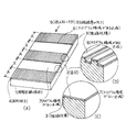
図1(a)のように、ホログラムパターンを形成する回折格子4を情報記録媒体1用の基材2の全表面に設け、その上にFe系強磁性薄膜3を膜厚0.2μmで形成し、磁気信号を調べた。ここで云う磁気信号は図2のブロック図に示される読み取り装置で交流励磁したときに得られる波形をさす。なお、図1(b)は図1(a)に示す情報記録媒体1の端面の一部拡大図である。図2において、11は図1に示す情報記録媒体1の如き被判定物、12は交流の励磁電源、13は励磁コイル、8は磁気ヘッド、9は増幅器、10はオシロスコープであり、5は読み取り方向(励磁磁界の向き)である。情報記録媒体1および磁気ヘッド8の一方を他方に対して走査の方向と直交する方向に沿って走行させる走行駆動機構には、通常の適宜の走行駆動機構を用いることができるので、図2でも図示を省略している。本実施例は磁気的挙動を確認するためシリコンウェハの鏡面を基材2として用い、回折格子4は半導体プロセス用ポジ型レジストで形成した。セキュリティで用いられる実際のホログラムは、基材・回折格子ともに同一材料の樹脂で形成される場合が多いが、磁気特性に対する基材材質効果は低く、むしろその形状に大きく左右されるので、実際のホログラムでも同様なパルス波が得られる。ホログラムを形成する回折格子4の凹凸の配置方向は励磁の磁束と平行になるように形成し、回折格子4のラインの幅αは2μm,スペースの幅βは1μm,高さγは0.4μmとした。このパターンによりホログラム固有の干渉色がみられた。磁気特性はホログラムの回折格子4の区域Aに影響を受けパルス波が図3(a)に示すように現れた。図3(b)は図3(a)の部分拡大図である。ホログラム領域がない図14に示す比較例1では、実施例1と同様に磁性体を形成しても波高値の小さいパルスが図15に示すように得られるだけであって、図3に示すような波高値の大きいパルスは現れない。図4は、図1(a)の変形例であり、図4(a)は回折格子4に規則的湾曲部4aを設けた例であり、図4(b)はこの場合の図3(a)に相当するパルス波であり、回折格子4に設けられた規則的な湾曲部4aの位置でパルス波の波高値が若干低下する。図5に示すようにホログラムを形成する回折格子4の凹凸配列が多くの方向に向いていれば、それら各方向に沿って読み取っても磁気信号は同一となり、ほぼ異方性がなく読み取り方向を選ばない磁気ホログラム情報記録媒体が得られる。
Example 1
As shown in FIG. 1A, a
(実施例2)
実施例1と同様に基材2としてシリコンウェハを用い、ホログラムを形成したが、この実施例2では図6(a)に示す通り、ホログラム領域がある区域6(A領域)とホログラ
ム領域がない区域7(平坦な領域X)が存在し、それらが交互に配置されている。その上にFe系強磁性薄膜3を膜厚0.2μmで形成し、磁気信号の変化を調べた。このときホログラム領域がある区域6では回折格子4が励磁の磁束と平行になるようにした。図6(b)の一部拡大図に示すホログラム領域がある区域6と図6(c)の一部拡大図に示すホログラム領域がない区域7で磁気信号がどうなるかを調べた。読み取り装置は、図2のブロック図に示される装置で、実施例1と同様である。回折格子4のラインは1μm,スペースは1μm,高さは0.4μmとした。このパターンによりホログラム固有の干渉色がみられ、ストライプ状に存在していることがわかる。この実施例2において、磁気特性はホログラム領域の有無に対応してパルス波の波高が図7(a)とその拡大図である図7(b)に示すように変化した(図7)。すなわち、ホログラム領域がある区域6(A領域)では図7(b)に示すように大きなパルスが現れ、ホログラム領域がない区域7(X領域)では図7(c)に示すようにパルスもブロードになり波高値も小さくなった。このように目視あるいは光学読み取り装置でホログラムパターンを読み取ることができると同時にそれに対応した磁気信号も読み取ることができる。
(Example 2)
As in Example 1, a silicon wafer was used as the
(実施例3)
実施例1と同様に基材2としてシリコンウェハを用い、図8(a)と図8(b)(c)の一部拡大図に示すように、ホログラムパターンを形成する回折格子4の凹凸の配列方向の角度を変えた回折格子4を同一面内に設け、その上にFe系強磁性薄膜3を膜厚0.2μmで形成し、磁気信号の変化を調べた。このときホログラムパターンは2種類で互いに角度が90°回転している。磁気読み取り信号は、図2のブロック図に示される読み取り装置で交流励磁したときに得られる波形である。回折格子4のラインは1μm,スペースは1μm,高さは0.4μmで共通で角度のみが異なる。このパターンによりホログラム固有の干渉色がみられ、角度の異なるホログラム領域間で色合いが異なり、ストライプを確認することができる。磁気特性はホログラムパターンを形成する回折格子4の凹凸の配列方向の角度に対応してパルス波が、図9(a)及び図9(b)(c)の一部拡大図に示すように、現れた。すなわち、パターンが0°(読み取り方向と回折格子4が平行:A領域)のときには図9(b)に示すように大きなパルスが現れ、90°(読み取り方向と回折格子が直交:B領域)のときには図9(c)に示すようにパルスもブロードになり波高値も小さくなった。目視あるいは光学読み取り装置でホログラムパターンが読み取れると同時にそれに対応した磁気信号を読み取ることができる。
(Example 3)
As in Example 1, a silicon wafer was used as the
(実施例4)
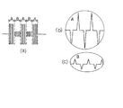
実施例1と同様に基材2としてシリコンウェハを用いた、円形の図柄を持つホログラムの例である。図10(a)及び一部拡大図である図10(b)に示すように、ホログラム回折格子4の角度が励磁の磁束と45°である一様なホログラム領域内に励磁の磁束と平行な回折格子4の角度を持つ円形のホログラム領域を設けた。その上にFe系強磁性薄膜を膜厚0.2μmで形成し、磁気信号の変化を調べた。磁気信号は図2のブロック図に示される読み取り装置で交流励磁したときに得られる波形である。なお、本実施例では、磁気ヘッド8の読み取り幅を情報記録媒体の幅より大きくしておくことにより、ホログラムの図柄を磁気信号出力により読み取ることができる。回折格子4のラインは1μm,スペース1μm,高さは0.4μmで共通の角度のみが異なる。これらのパターンによりホログラム固有の干渉色がみられ、円形のホログラム領域Aと他の領域Cは異なる色合いとなった。磁気特性はホログラムパターンに対応してパルス波が、図11(a)とその拡大図である図11(b)(c)に示すように現れた。すなわち、パターンが45°(読み取り方向と回折格子4が45°)のときは小さなパルスが現れ、0°(読み取り方向と回折格子4が平行:A領域)である円形の図柄が現れるにしたがってパルスは次第に大きくなりやがて減少し、図柄を通り過ぎると図11(c)に示すように元の小さいなパルスとなった。このように目視あるいは光学読み取り装置で円形のホログラムパターンが読み取れると同時にそれに対応した磁気信号を読み取ることができる。
Example 4
This is an example of a hologram having a circular pattern using a silicon wafer as the
上記実施例では単純なホログラムパターンについてのみ磁気特性を確認したが、セキュリティでよく用いられる立体画像を再生するホログラムパターンなどの複雑なパターンについても本発明による情報記録媒体がそのパターンに特徴づけられる磁気気性を有し、特殊な材料を用いなくても他磁性膜とは識別可能なものとすることが可能であることは容易に推察できる。 In the above embodiment, the magnetic characteristics were confirmed only for a simple hologram pattern. However, the information recording medium according to the present invention is also characterized by the pattern for complex patterns such as a hologram pattern for reproducing a stereoscopic image often used in security. It can be easily inferred that it can be distinguished from other magnetic films without using special materials.
(実施例5)
実施例1と同様に基材2としてシリコンウェハを用い、文字「A」の図柄を持つホログラムパターンの例である。図12に示すようにホログラム回折格子4の凹凸の配列角度が励磁の磁束と45°である一様なホログラム領域内に励磁の磁束と平行な回折格子4の凹凸の配列角度を持つ文字「A」の形をしたホログラム領域を設けた。その上にFe系強磁性薄膜を膜厚0.2μmで形成した。回折格子4のラインの幅は1μm、スペースの幅は1μm、高さは0.4μmで共通で角度のみが異なる。これらパターンによりホログラム固有の干渉色がみられ、「A」の形をしたホログラム領域と他の領域は異なる色合いとなる。図2のブロック図に示される読み取り装置を用い、図12に示すように磁気ヘッドの読み取り幅を例えば、文字「A」より充分小さくし情報記録媒体1の例えば幅方向の如き一定方向に対し20分割となるようにCH1 〜CH20の磁気ヘッド8を配置し、例えば(1)(2)(3)……(14)のように一定間隔毎に情報記録媒体1を一時停止させる調歩的又は連続的な走行駆動をして、図2では図示されていない適宜のスイッチング回路を用いて、その一時停止中に磁気ヘッド8のCH1 〜CH20を順次切り換える走査を行って読み取り出力パルス出力を発生させるように読み取り装置を動作させれば、図13に示すように「A」の形に対応してパルス波が現れる。すなわち、パターンが45°(読み取り方向と回折格子が45°)のときは小さなパルスが現れ、パターンが0°(読み取り方向と回折格子が平行)である文字「A」の図柄が現れる領域ではパルスは大きくなり、文字「A」を通り過ぎると元の小さなパルスとなる。なお、単一の磁気ヘッド8を前記一定方向に沿って移動させる構成により前記の走査をしてもよく、さらに情報記録媒体1の走行駆動は前記一定の方向の走査速度より例えば1/10程度以上低い走行速度であって、前の調歩的駆動に限らず連続的駆動を採用することができる。情報記録媒体1および磁気ヘッド8の一方を他方に対して走査の方向と直交する方向に沿って走行させる走行駆動機構には、通常の適宜の走行駆動機構を用いることができるので、図2でも図示を省略している。このように目視あるいは光学読み取り装置で「A」のホログラムパターンが読み取れると同時にそれぞれに対応した磁気信号を読み取ることができる。
(Example 5)
This is an example of a hologram pattern using a silicon wafer as the
すなわち、このような構成により、基材(2)と、該基材の表面上に規則的または不規則的に設けた回折格子(4)の凹凸が該回折格子の凹凸からの反射光でホログラムパターンとして観測されるように形成されたホログラム領域(A)と、該ホログラム領域の上に形成された強磁性体薄膜(3)とを備え、偽造防止のための管理情報として該強磁性体薄膜に該ホログラムパターンまたは該ホログラム領域の形状パターンに応じた特徴的な磁気特性を保持させた情報記録媒体(1)を対象として、該情報記録媒体の前記ホログラム領域を一定の方向(5)に沿って交流励磁する励磁手段(12,13)と、該情報記録媒体からの前記交流励磁による出力信号を該ホログラム領域の前記一定の方向に沿って順次走査して取り出す磁気ヘッド手段(8)と、該情報記録媒体および前記磁気ヘッド手段の一方を、他方に対して前記走査の方向と直交する送り方向に沿って該走査の速度より十分低い走行速度で連続的にもしくは調歩的に走行駆動する走行駆動手段と、前記磁気ヘッド手段からの前記出力信号を前記順次走査と前記走行駆動に同期して可視表示する可視表示手段(10)とを備え、前記該ホログラムパターンまたは該ホログラム領域の形状パターンに応じた信号パターンが該可視表示手段により観測されるように形成された情報読み取り装置が実現される。 That is, with such a configuration, the unevenness of the base material (2) and the diffraction grating (4) regularly or irregularly provided on the surface of the base material is reflected by the reflected light from the unevenness of the diffraction grating. A hologram thin film (A) formed so as to be observed as a pattern, and a ferromagnetic thin film (3) formed on the hologram light, and the ferromagnetic thin film as management information for preventing forgery The information recording medium (1) having characteristic magnetic properties corresponding to the hologram pattern or the shape pattern of the hologram area as a target, the hologram area of the information recording medium along a certain direction (5) Excitation means (12, 13) for AC excitation, and magnetic head means for sequentially scanning out the output signal from the information recording medium by the AC excitation along the fixed direction of the hologram area. 8) and continuously or stepwisely moving one of the information recording medium and the magnetic head means at a traveling speed sufficiently lower than the scanning speed along the feeding direction perpendicular to the scanning direction with respect to the other. Travel driving means for traveling driving; and visual display means (10) for visually displaying the output signal from the magnetic head means in synchronization with the sequential scanning and the traveling driving, the hologram pattern or the hologram region An information reading device formed so that a signal pattern corresponding to the shape pattern is observed by the visible display means is realized.
(比較例1)
回折格子4を形成していない基材2に、図14(a)とその一部拡大図である図14(b)に示すように、シリコンウェハと磁性体にはFe系強磁性材料を用い、膜厚0.2μmの磁性膜を形成し(X領域)、磁気特性を確認した。実施例1と同一方向の磁気信号を図15(a)とその一部拡大図である図15(b)に示す。得られるX領域の磁気信号はブロードなパルスであり、ホログラム領域が存在する場合とは明らかに異なることがわかる。
(Comparative Example 1)
As shown in FIG. 14A and a partially enlarged view of FIG. 14B on the
図16(a)(b)はプリペイドカード、金券類などのプラスチック、紙からなる薄くて四角い高付加価値商品の表面に本発明の情報記録媒体を接着し、転写などの方法で貼り付けた例である。 16 (a) and 16 (b) are examples in which the information recording medium of the present invention is adhered to the surface of a thin and high-value-added product made of plastic, paper such as prepaid cards and gold vouchers, and pasted by a method such as transfer. It is.
1 情報記録媒体
2 基材
3 強磁性膜(強磁性体薄膜)
4 回折格子
4a,4b 湾曲部
5 読み取り方向(励磁磁界の向き)
6 ホログラムがある領域(有り区域)
7 ホログラムがない領域(無し区域)
8 磁気ヘッド
9 増幅器
10 オシロスコープ
11 被判定物(情報記録媒体)
12 励磁電源
13 励磁コイル
14 プリペイドカード
15 金券類
1
4 Diffraction gratings 4a and 4b
6 Area with hologram (existing area)
7 Area without hologram (None area)
8
12
Claims (6)
Priority Applications (1)
| Application Number | Priority Date | Filing Date | Title |
|---|---|---|---|
| JP2007110292A JP4627767B2 (en) | 2007-04-19 | 2007-04-19 | Information recording medium |
Applications Claiming Priority (1)
| Application Number | Priority Date | Filing Date | Title |
|---|---|---|---|
| JP2007110292A JP4627767B2 (en) | 2007-04-19 | 2007-04-19 | Information recording medium |
Related Parent Applications (1)
| Application Number | Title | Priority Date | Filing Date |
|---|---|---|---|
| JP8823798A Division JP3964536B2 (en) | 1998-03-18 | 1998-03-18 | Information recording medium |
Publications (2)
| Publication Number | Publication Date |
|---|---|
| JP2007213094A true JP2007213094A (en) | 2007-08-23 |
| JP4627767B2 JP4627767B2 (en) | 2011-02-09 |
Family
ID=38491503
Family Applications (1)
| Application Number | Title | Priority Date | Filing Date |
|---|---|---|---|
| JP2007110292A Expired - Lifetime JP4627767B2 (en) | 2007-04-19 | 2007-04-19 | Information recording medium |
Country Status (1)
| Country | Link |
|---|---|
| JP (1) | JP4627767B2 (en) |
Cited By (1)
| Publication number | Priority date | Publication date | Assignee | Title |
|---|---|---|---|---|
| KR101170657B1 (en) | 2010-08-09 | 2012-08-07 | 한국조폐공사 | A sheet for counterfeit prevention with diffracting grating and its manufacturing method |
Citations (9)
| Publication number | Priority date | Publication date | Assignee | Title |
|---|---|---|---|---|
| JPH04222084A (en) * | 1990-12-22 | 1992-08-12 | Nhk Spring Co Ltd | Bar code structure, its reading structure and reading method |
| JPH0573738A (en) * | 1991-04-16 | 1993-03-26 | Nhk Spring Co Ltd | Object discriminating structure |
| JPH06203421A (en) * | 1993-01-05 | 1994-07-22 | Dainippon Printing Co Ltd | Method for optically and magnetically recording and reading information and optical and magnetic recording medium |
| JPH08161449A (en) * | 1994-12-05 | 1996-06-21 | Dainippon Printing Co Ltd | Diffraction grating recording medium and preparing method for the same |
| JPH09157556A (en) * | 1995-12-08 | 1997-06-17 | Iwatsu Electric Co Ltd | Magnetic ink and magnetic thermosensitive transfer material |
| JPH09220892A (en) * | 1996-02-19 | 1997-08-26 | Toppan Printing Co Ltd | Hologram pattern intended for anticopying and article applied therewith |
| JPH1055533A (en) * | 1996-08-12 | 1998-02-24 | Iwatsu Electric Co Ltd | Recording medium having ferromagnetic substance film |
| JPH1064051A (en) * | 1996-08-14 | 1998-03-06 | Iwatsu Electric Co Ltd | Magnetic plate with magnetic patterning and its production |
| JPH10105031A (en) * | 1996-09-30 | 1998-04-24 | Iwatsu Electric Co Ltd | Information recording medium |
-
2007
- 2007-04-19 JP JP2007110292A patent/JP4627767B2/en not_active Expired - Lifetime
Patent Citations (9)
| Publication number | Priority date | Publication date | Assignee | Title |
|---|---|---|---|---|
| JPH04222084A (en) * | 1990-12-22 | 1992-08-12 | Nhk Spring Co Ltd | Bar code structure, its reading structure and reading method |
| JPH0573738A (en) * | 1991-04-16 | 1993-03-26 | Nhk Spring Co Ltd | Object discriminating structure |
| JPH06203421A (en) * | 1993-01-05 | 1994-07-22 | Dainippon Printing Co Ltd | Method for optically and magnetically recording and reading information and optical and magnetic recording medium |
| JPH08161449A (en) * | 1994-12-05 | 1996-06-21 | Dainippon Printing Co Ltd | Diffraction grating recording medium and preparing method for the same |
| JPH09157556A (en) * | 1995-12-08 | 1997-06-17 | Iwatsu Electric Co Ltd | Magnetic ink and magnetic thermosensitive transfer material |
| JPH09220892A (en) * | 1996-02-19 | 1997-08-26 | Toppan Printing Co Ltd | Hologram pattern intended for anticopying and article applied therewith |
| JPH1055533A (en) * | 1996-08-12 | 1998-02-24 | Iwatsu Electric Co Ltd | Recording medium having ferromagnetic substance film |
| JPH1064051A (en) * | 1996-08-14 | 1998-03-06 | Iwatsu Electric Co Ltd | Magnetic plate with magnetic patterning and its production |
| JPH10105031A (en) * | 1996-09-30 | 1998-04-24 | Iwatsu Electric Co Ltd | Information recording medium |
Cited By (1)
| Publication number | Priority date | Publication date | Assignee | Title |
|---|---|---|---|---|
| KR101170657B1 (en) | 2010-08-09 | 2012-08-07 | 한국조폐공사 | A sheet for counterfeit prevention with diffracting grating and its manufacturing method |
Also Published As
| Publication number | Publication date |
|---|---|
| JP4627767B2 (en) | 2011-02-09 |
Similar Documents
| Publication | Publication Date | Title |
|---|---|---|
| US7891567B2 (en) | Identification tag, object adapted to be identified, and related methods, devices, and systems | |
| US6502757B1 (en) | Information recorded medium, device for reading the information, information recorded medium transfer foil, and method for producing information recorded medium | |
| JP2009537044A (en) | Object identification method, identification tag, object configured to be identified, and related devices and systems | |
| JP2004077954A (en) | Medium and method for confirming authenticity | |
| JPH10105031A (en) | Information recording medium | |
| JP4780319B2 (en) | Authentic proof optical structure, authenticity proof recording body, and authenticity confirmation method | |
| JP3964536B2 (en) | Information recording medium | |
| JP4627767B2 (en) | Information recording medium | |
| JP2001202491A (en) | Ic card with improved forgery prevention effect | |
| US5032709A (en) | Magnetic card | |
| JP4946155B2 (en) | Security media reader | |
| JP4946154B2 (en) | Security media reader | |
| JP2003268698A (en) | Information-recording paper and method for utilizing information-recording paper | |
| JPH1064051A (en) | Magnetic plate with magnetic patterning and its production | |
| JP2009000910A (en) | Anticounterfeit medium | |
| JP2009003182A (en) | Forgery prevention medium | |
| JP2001236477A (en) | Thermal magnetic recording medium | |
| JP2001134728A (en) | Thermosensible magnetic recording medium and recording/ reading-reproducing method | |
| JP2000137914A (en) | Magnetic recording medium and its production | |
| JP2000082208A (en) | Magnetic bar code and its recording method | |
| JP4095203B2 (en) | Magnetic recording medium and method for manufacturing the same | |
| JP2613854B2 (en) | Composite magnetic recording media | |
| JP2000137913A (en) | Magnetic recording medium and its production | |
| JPH0899484A (en) | Card and method for discriminating genuine card from fake | |
| JPH06255293A (en) | Magnetic card |
Legal Events
| Date | Code | Title | Description |
|---|---|---|---|
| A131 | Notification of reasons for refusal |
Free format text: JAPANESE INTERMEDIATE CODE: A131 Effective date: 20090929 |
|
| A521 | Written amendment |
Free format text: JAPANESE INTERMEDIATE CODE: A523 Effective date: 20091130 |
|
| A131 | Notification of reasons for refusal |
Free format text: JAPANESE INTERMEDIATE CODE: A131 Effective date: 20100223 |
|
| A521 | Written amendment |
Free format text: JAPANESE INTERMEDIATE CODE: A523 Effective date: 20100423 |
|
| A131 | Notification of reasons for refusal |
Free format text: JAPANESE INTERMEDIATE CODE: A131 Effective date: 20100817 |
|
| A521 | Written amendment |
Free format text: JAPANESE INTERMEDIATE CODE: A523 Effective date: 20101008 |
|
| TRDD | Decision of grant or rejection written | ||
| A01 | Written decision to grant a patent or to grant a registration (utility model) |
Free format text: JAPANESE INTERMEDIATE CODE: A01 Effective date: 20101102 |
|
| A01 | Written decision to grant a patent or to grant a registration (utility model) |
Free format text: JAPANESE INTERMEDIATE CODE: A01 |
|
| A61 | First payment of annual fees (during grant procedure) |
Free format text: JAPANESE INTERMEDIATE CODE: A61 Effective date: 20101108 |
|
| FPAY | Renewal fee payment (event date is renewal date of database) |
Free format text: PAYMENT UNTIL: 20131119 Year of fee payment: 3 |
|
| R150 | Certificate of patent or registration of utility model |
Free format text: JAPANESE INTERMEDIATE CODE: R150 |
|
| EXPY | Cancellation because of completion of term |