JP2011106989A - Vortex flowmeter - Google Patents
Vortex flowmeter Download PDFInfo
- Publication number
- JP2011106989A JP2011106989A JP2009262943A JP2009262943A JP2011106989A JP 2011106989 A JP2011106989 A JP 2011106989A JP 2009262943 A JP2009262943 A JP 2009262943A JP 2009262943 A JP2009262943 A JP 2009262943A JP 2011106989 A JP2011106989 A JP 2011106989A
- Authority
- JP
- Japan
- Prior art keywords
- vibration
- gyro
- vortex
- detection
- control circuit
- Prior art date
- Legal status (The legal status is an assumption and is not a legal conclusion. Google has not performed a legal analysis and makes no representation as to the accuracy of the status listed.)
- Granted
Links
Images


Landscapes
- Measuring Volume Flow (AREA)
- Vibration Prevention Devices (AREA)
Abstract
【課題】渦流量計の耐振性を向上させる渦流量計を実現する。
【解決手段】管路本体に取り付けられたケースを具備し、カルマン渦による交番圧力の変動を渦発生体に設けられた応力検出素子で検出して流速流量を測定する渦流量計において、前記ケースに設けられXYZ軸方向のケース振動のノイズをそれぞれ検出する3軸ジャイロと、この3軸ジャイロで検出された振動信号に基づきこのジャイロ検出振動信号と逆位相の振動信号を出力する振動制御回路と、前記3軸ジャイロのケースに前記XYZ軸に直交してそれぞれ一方の面が設けられ前記振動制御回路からの信号に基づき前記ジャイロ検出振動信号を打ち消す振動を発生する圧電アクチュエータと、この圧電アクチュエータの他方の面にそれぞれ一面が設けられた付加質量とを有する振動検出発生ユニットを具備したことを特徴とする渦流量計である。
【選択図】図1An object of the present invention is to realize a vortex flowmeter that improves the vibration resistance of the vortex flowmeter.
A vortex flowmeter comprising a case attached to a pipe body, wherein a flow rate flow rate is measured by detecting a change in alternating pressure due to a Karman vortex by a stress detection element provided in the vortex generator. A three-axis gyro for detecting noise in case vibrations in the XYZ-axis directions, and a vibration control circuit for outputting a vibration signal having a phase opposite to that of the gyro-detection vibration signal based on the vibration signal detected by the three-axis gyro. A piezoelectric actuator that is provided with one surface orthogonal to the XYZ axes on the case of the three-axis gyro and generates a vibration that cancels the gyro detection vibration signal based on a signal from the vibration control circuit; Vortex flow rate characterized by comprising a vibration detection and generation unit having an additional mass each provided with one surface on the other surface It is.
[Selection] Figure 1
Description
本発明は、渦流量計に関するものである。
更に詳述すれば、本発明は渦流量計の耐振性向上に関するものである。
The present invention relates to a vortex flowmeter.
More specifically, the present invention relates to an improvement in vibration resistance of a vortex flowmeter.
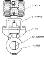
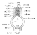
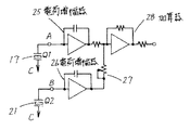
図7は従来より一般に使用されている従来例の構成説明図、図8は図7の要部構成説明図、図9は図7の電気回路図、図10,図11は図7の動作説明図である。 FIG. 7 is a diagram illustrating the configuration of a conventional example that is generally used, FIG. 8 is a diagram illustrating the configuration of the main part of FIG. 7, FIG. 9 is an electrical circuit diagram of FIG. 7, and FIGS. FIG.
図において、本体1の下部には、管路10が設けられている。
本体1の上部には逆U字状のブラケット2が設けられ、その上部にはケース3が設けられている。
管路10は測定流体FLが流れる管路である。
ノズル11は管路10に直角に設けられ円筒状をなす。
渦発生体12は、ノズル11とは隙間を保って、管路10に直角に挿入され、台形断面を有す。
In the figure, a
An inverted
The
The
The
渦発生体12の一端は、ネジ13により管路10に支待され、他端はフランジ部14でノズル11にネジ或いは溶接により固定されている。
凹部15は、渦発生体12のフランジ部14側に設けられている。
One end of the
The concave portion 15 is provided on the flange portion 14 side of the
この凹部15の中には、その底部から順に、全属製の第1コモン電極16、圧電素子17、電極板18、絶縁板19、電極板20、圧電素子21が、サンドイッチ状に配列され、全属製の押圧棒22により、これ等は押圧固定されている。
さらに、電極板18からは、リード線23、電極板20からはリード線24が、それぞれ端子A、Bに引き出されている。
In the recess 15, all the first common electrodes 16, the
Further, a lead wire 23 is drawn from the electrode plate 18 and a lead wire 24 is drawn from the
圧電素子17、21は、各圧電素子17、21の紙面に向かって左側と右側とがそれぞれ逆方向に分極されており、同じ方向の応力に対して互いに上下の電極に逆極性の電荷を発生する。
The
圧電素子17に発生した電荷は、電極板18と接続された端子Aと、第1コモン電極16を介して接続された管路10との間に得られ、圧電素子21に発生した電荷は、電極板20と接続された端子Bと、押圧棒20と接続された管路10との間に得られる。
The electric charge generated in the
この2個の電極板18、20に発生した電荷は、図11に示すように電荷増幅器25、26に入力される。
電荷増幅器25の出力と、電荷増幅器26の出力をボリウム27を介した出力とを、加算器28で加算して流量信号を得る。
The charges generated in the two
The output of the charge amplifier 25 and the output of the charge amplifier 26 via the
この流量信号は、例えば、電流出力に変換されて、2線を介して負荷に伝送される(図示せず。)。
次に、以上のように構成された渦流量計の動作について、図10と図11とを用いて説明する。
This flow rate signal is converted into a current output, for example, and transmitted to a load via two wires (not shown).
Next, the operation of the vortex flowmeter configured as described above will be described with reference to FIGS. 10 and 11.
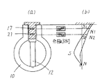
測定流体FLが管路10の中に流れると、渦発生体12に矢印Fで示した方向にカルマン渦による振動が発生する。
この振動により渦発生体12には、図10(a)に示すような応力分布と、この逆の応力分布の繰返しが生じる。
When the measurement fluid FL flows into the
This vibration causes the
各圧電素子17、21には、図10(a)に示す渦周波数を持つ信号応力に対応した電荷+Q、−Qの繰返しが生じる。
なお、図10においては、説明の便宣のため、電極板18或いは21を紙面に対して左石に2つに分割し、かつ、上下の一方の電極は、第1コモン電極16あるいは押圧棒22に相当するものとしてある。
In each of the
In FIG. 10, for convenience of explanation, the
一方、管路10には、ノイズとなる管路振動も生じる。
この管路振動は、
(1)流体の流れと同じ方向の抗力方向、
(2)流体の流れとは直角方向の揚力方向、
(3)渦発生体の長手方向の3方向成分に分けられる。
On the other hand, the
This pipe vibration is
(1) Drag direction in the same direction as the fluid flow,
(2) Lift direction perpendicular to the fluid flow,
(3) Divided into three components in the longitudinal direction of the vortex generator.
このうち、抗力方向の振動に対する応力分布は、図10(b)に示すようになり、1個の電極内で正負の電荷は打ち消されて、ノイズ電荷は発生しない。
また、長手方向の振動に対しては、図10(c)に示すように、電極内で打ち消されて、抗力方向と同様にノイズ電荷は発生しない。
Among these, the stress distribution with respect to the vibration in the drag direction is as shown in FIG. 10B, and the positive and negative charges are canceled out within one electrode, and no noise charge is generated.
Further, as shown in FIG. 10C, the vibration in the longitudinal direction is canceled within the electrode, and no noise charge is generated as in the drag direction.
しかし、揚力方向の振動は、信号応力と同一の応力分布となり、ノイズ電荷が生じる。
そこで、このノイズ電荷を消去するために、以下の演算を実行する。
However, the vibration in the lift direction has the same stress distribution as the signal stress, and noise charges are generated.
Therefore, in order to eliminate this noise charge, the following calculation is executed.
圧電素子17,21の各電荷をQ1,Q2、信号成分をQ1,Q2、揚力方向のノィズ成分をN1,N2とし、圧電素子17,21で分極を逆とすると、Q1,Q2は次式で示される。
When the electric charges of the
Q1=S1+N1
−Q2=−S2一N2
ただし、S1とS2、N1とN2のベクトル方向は同じである。
Q1 = S1 + N1
-Q2 = -S2 N2
However, the vector directions of S1 and S2 and N1 and N2 are the same.
ここで、圧電素子17、21の信号成分とノイズ成分の関係は、図9(この図は揚力方向のノイズと、信号に対する渦発生体の曲げモーメントの関係を示す)に示すようになっている。
Here, the relationship between the signal component and the noise component of the
従って、図9に示すように、圧電素子17側の電荷増幅器25の出力を、加算器28で加算する際に、ボリウム27と共に、N1/N2倍して、圧電素子21側の電荷増幅器26の出力と加算すると、
Therefore, as shown in FIG. 9, when the output of the charge amplifier 25 on the
Q1−Q2(N1/N2)
=S1−S2(N1/N2)
となり管路ノイズは除去される。
Q1-Q2 (N1 / N2)
= S1-S2 (N1 / N2)
Next, the pipe line noise is removed.
そして、第1コモン電極16、圧電素子17、電極板18、絶縁板19、電極板20、圧電素子21は、凹部15に押圧棒22で押圧固定されている。
The first common electrode 16, the
ここで、渦発生体12と第1コモン電極16、圧電素子17、電極板18、絶縁板19、電極板20、圧電素子21、押圧棒22との温度膨脹を等しくしておけば、測定流体温度が変化しても、初期の押付け力は変化しないので、間題は生じ無い。
Here, if the temperature expansion of the
このような装置においては、以下の問題点がある。
ケースの振動により伝わる振動ノイズは、ブラケットを、圧電素子の感度がある揚力方向に剛性を高めることで、管路本体部に振動を伝え難くすることで、耐振性を向上させる工夫がされている。
Such an apparatus has the following problems.
The vibration noise transmitted by the vibration of the case has been devised to improve vibration resistance by making the bracket difficult to transmit vibration to the pipe body by increasing the rigidity in the lift direction with the sensitivity of the piezoelectric element. .
しかしながら、ブラケットの剛性だけでは限界があり、どうしても、ケースの振動が渦発生体から圧電素子に伝わり、振動ノイズの電荷が発生、流量がゼロの状態での誤出力や、流量がある状態での渦周波数の測定に影響を及ぼすことがある。
特に、ケース及びブラケットの部分(以下「トップワーク」と呼ぶ)が共振してしまうと、振動の振幅が大きくなり、振動ノイズをキャンセルすることが困難になっていた。
However, the rigidity of the bracket is limited, and the vibration of the case is inevitably transmitted from the vortex generator to the piezoelectric element, generating vibration noise charges, erroneous output when the flow rate is zero, and when there is a flow rate. May affect eddy frequency measurement.
In particular, when the case and bracket portions (hereinafter referred to as “top work”) resonate, the amplitude of vibration increases, making it difficult to cancel vibration noise.
本発明の目的は、上記の課題を解決するもので、トップワークの振動をアクティブに制振することで、トップワークから伝わる振動ノイズを減衰させ、渦流量計の耐振性を向上させる渦流量計を提供することにある。 The object of the present invention is to solve the above-mentioned problems, and by actively controlling the vibration of the top work, the vibration noise transmitted from the top work is attenuated and the vibration resistance of the vortex flowmeter is improved. Is to provide.
このような課題を達成するために、本発明では、請求項1の渦流量計においては、
管路本体に取り付けられたケースを具備し、カルマン渦による交番圧力の変動を渦発生体に設けられた応力検出素子で検出して流速流量を測定する渦流量計において、前記ケースに設けられXYZ軸方向のケース振動のノイズをそれぞれ検出する3軸ジャイロと、この3軸ジャイロで検出された振動信号に基づきこのジャイロ検出振動信号と逆位相の振動信号を出力する振動制御回路と、前記3軸ジャイロのケースに前記XYZ軸に直交してそれぞれ一方の面が設けられ前記振動制御回路からの信号に基づき前記ジャイロ検出振動信号を打ち消す振動を発生する圧電アクチュエータと、この圧電アクチュエータの他方の面にそれぞれ一面が設けられた付加質量とを有する振動検出発生ユニットを具備したことを特徴とする。
In order to achieve such a problem, in the present invention, in the vortex flowmeter of claim 1,
An eddy flow meter comprising a case attached to a pipe body and detecting a change in alternating pressure due to a Karman vortex by a stress detecting element provided in the vortex generator to measure a flow velocity and flow rate. A three-axis gyro for respectively detecting axial vibrations of the case vibration, a vibration control circuit for outputting a vibration signal having a phase opposite to that of the gyro-detection vibration signal based on the vibration signal detected by the three-axis gyro; A gyro case is provided with one surface orthogonal to the XYZ axes, and generates a vibration that cancels the gyro detection vibration signal based on a signal from the vibration control circuit, and on the other surface of the piezoelectric actuator And a vibration detection and generation unit having an additional mass each provided with one surface.
本発明の請求項2の渦流量計においては、
管路本体に取り付けられたケースを具備し、カルマン渦による交番圧力の変動を渦発生体に設けられた応力検出素子で検出して流速流量を測定する渦流量計において、前記渦発生体に設けられXYZ軸方向の振動ノイズをそれぞれ検出する3軸ジャイロと、この3軸ジャイロで検出された振動信号に基づきこのジャイロ検出振動信号と逆位相の振動信号を出力する振動制御回路と、前記3軸ジャイロのケースに前記XYZ軸に直交してそれぞれ一方の面が設けられ前記振動制御回路からの信号に基づき前記ジャイロ検出振動信号を打ち消す振動を発生する圧電アクチュエータと、この圧電アクチュエータの他方の面にそれぞれ一面が設けられた付加質量とを有する振動検出発生ユニットを具備したことを特徴とする。
In the vortex flowmeter according to
A vortex flowmeter comprising a case attached to a pipe body and detecting a change in alternating pressure due to a Karman vortex by a stress detection element provided in the vortex generator to measure a flow velocity and flow rate. A three-axis gyro that respectively detects vibration noise in the XYZ-axis direction, a vibration control circuit that outputs a vibration signal having a phase opposite to that of the gyro-detection vibration signal based on the vibration signal detected by the three-axis gyro, and the three-axis gyro A gyro case is provided with one surface orthogonal to the XYZ axes, and generates a vibration that cancels the gyro detection vibration signal based on a signal from the vibration control circuit, and on the other surface of the piezoelectric actuator And a vibration detection and generation unit having an additional mass each provided with one surface.
本発明の請求項3の渦流量計においては、
管路本体に取り付けられたケースを具備し、カルマン渦による交番圧力の変動を渦発生体に設けられた応力検出素子で検出して流速流量を測定する渦流量計において、前記渦流量計の前記カルマン渦による交番圧力の変動を検出しない位置に設けられXYZ軸方向の振動ノイズをそれぞれ検出する3軸ジャイロと、この3軸ジャイロで検出された振動信号に基づきこのジャイロ検出振動信号と逆位相の振動信号を出力する振動制御回路と、前記渦発生体に設けられ前記3軸ジャイロの前記XYZ軸に対応して一方の面が設けられ前記振動制御回路からの信号に基づき前記ジャイロ検出振動信号を打ち消す振動を発生する圧電アクチュエータと、この圧電アクチュエータの他方の面にそれぞれ一面が設けられた付加質量とを有する振動検出発生ユニットを具備したことを特徴とする。
In the vortex flowmeter according to
A vortex flowmeter comprising a case attached to a pipe body, wherein a flow rate flow rate is measured by detecting a change in alternating pressure due to a Karman vortex by a stress detecting element provided in the vortex generator. A three-axis gyro that is provided at a position that does not detect a change in alternating pressure due to Karman vortex and detects vibration noise in the X, Y, and Z-axis directions, and based on a vibration signal detected by the three-axis gyro, A vibration control circuit for outputting a vibration signal; and one surface corresponding to the XYZ axes of the three-axis gyro provided on the vortex generator, and the gyro detection vibration signal based on a signal from the vibration control circuit. Vibration detection and generation including a piezoelectric actuator that generates a vibration to cancel and an additional mass each provided on one side of the piezoelectric actuator Characterized by comprising a knit.
本発明の請求項1によれば、次のような効果がある。
3軸ジャイロで検出した振動と逆位相の振動を圧電アクチュエータで発生させることにより、ケースの振動を減衰させることができる。
ケースの振動が減衰することで、S/N比が向上し、従来よりも耐振性の高い渦流量計が得られる。
According to claim 1 of the present invention, there are the following effects.
The vibration of the case can be attenuated by causing the piezoelectric actuator to generate a vibration having a phase opposite to that detected by the three-axis gyro.
Since the vibration of the case is attenuated, the S / N ratio is improved and a vortex flowmeter having higher vibration resistance than the conventional one can be obtained.
本発明の請求項2によれば、次のような効果がある。
渦信号として存在し得ない帯域の周波数を振動検出発生ユニットが検出した場合、渦発生体に振動と逆位相の強制振動を与え、渦発生体に発生する振動ノイズをキャンセルする。
限定周波数帯域で効果がある渦流量計が得られる。
According to
When the vibration detection and generation unit detects a frequency in a band that cannot exist as a vortex signal, a forced vibration having a phase opposite to that of the vibration is applied to the vortex generator to cancel the vibration noise generated in the vortex generator.
A vortex flowmeter that is effective in a limited frequency band can be obtained.
本発明の請求項3によれば、次のような効果がある。
ケース振動によるノイズ成分だけでなく、渦発生体の自重により生じる振動ノイズもキャンセルすることができる。
全周波数帯域で耐振性を向上出来る渦流量計が得られる。
According to
Not only noise components due to case vibration but also vibration noise caused by the weight of the vortex generator can be canceled.
A vortex flowmeter that can improve vibration resistance in all frequency bands can be obtained.
以下本発明を図面を用いて詳細に説明する。
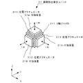
図1は本発明の一実施例の要部構成説明図でケース部分を拡大した説明図で、(a)は正面図、(b)は側面図である。
Hereinafter, the present invention will be described in detail with reference to the drawings.
1A and 1B are explanatory views in which a case portion is enlarged in an explanatory view of a main part configuration of an embodiment of the present invention, in which FIG. 1A is a front view and FIG. 1B is a side view.
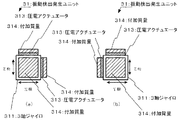
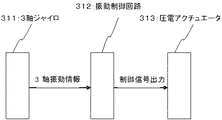
図2は図1の要部詳細斜視説明図、図3(a)はY軸方向より見た図、図3(a)はX軸方向より見た図、図4は図2の電気回路のブロック図である。
図において、図7と同一記号の構成は同一機能を表す。
以下、図7との相違部分のみ説明する。
2 is a detailed perspective view of the main part of FIG. 1, FIG. 3 (a) is a view seen from the Y-axis direction, FIG. 3 (a) is a view seen from the X-axis direction, and FIG. It is a block diagram.
In the figure, the same symbol structure as in FIG. 7 represents the same function.
Only the difference from FIG. 7 will be described below.
図1、図2、図3において、振動検出発生ユニット31は、3軸ジャイロ311と振動制御回路312と圧電アクチュエータ313と付加質量314とを有する。
3軸ジャイロ311は、ケース3に設けられXYZ軸方向のケース3の振動のノイズをそれぞれ検出する。
1, 2, and 3, the vibration detection and generation unit 31 includes a three-axis gyro 311, a vibration control circuit 312, a piezoelectric actuator 313, and an additional mass 314.
The triaxial gyro 311 is provided in the
図4に示す如く、振動制御回路312は、3軸ジャイロ311で検出された振動信号に基づき、このジャイロ検出振動信号と逆位相の振動信号を出力する。
圧電アクチュエータ313は、3軸ジャイロ311のケースにXYZ軸に直交してそれぞれ一方の面が設けられ、振動制御回路312からの信号に基づき、3軸ジャイロ311の検出振動信号を打ち消す振動を発生する。
付加質量314は、圧電アクチュエータ313の他方の面にそれぞれ一面が設けられている。
As shown in FIG. 4, the vibration control circuit 312 outputs a vibration signal having a phase opposite to that of the gyro detection vibration signal based on the vibration signal detected by the three-axis gyro 311.
The piezoelectric actuator 313 is provided with one surface on the case of the triaxial gyro 311 orthogonal to the XYZ axes, and generates vibration that cancels the vibration signal detected by the triaxial gyro 311 based on a signal from the vibration control circuit 312. .
One surface of the additional mass 314 is provided on the other surface of the piezoelectric actuator 313.
以上の構成において、図1に示すように、ケース3の内部に振動検出発生ユニット31を取り付ける。
ケース3の振動を3軸ジャイロ311で検出し、検出したそれぞれの軸方向振動に対し、振動制御回路312からの信号に基づき、逆位相で圧電アクチュエータ313を振動させケース3の振動を減衰させる。
In the above configuration, as shown in FIG. 1, the vibration detection generating unit 31 is attached inside the
The vibration of the
この結果、
3軸ジャイロ311で検出した振動と逆位相の振動を圧電アクチュエータ313で発生させることにより、ケース3の振動を減衰させることができる。
ケース3の振動が減衰することで、S/N比が向上し、従来よりも耐振性の高い渦流量計が得られる。
As a result,
The vibration of the
Since the vibration of the
図5は、本発明の他の実施例の要部構成説明図である。
図5において、振動検出発生ユニット41は、3軸ジャイロ411と振動制御回路412と圧電アクチュエータ413と付加質量414とを有する。
3軸ジャイロ411は、渦発生体12に設けられ、XYZ軸方向の振動ノイズをそれぞれ検出する。
FIG. 5 is an explanatory view showing the configuration of the main part of another embodiment of the present invention.
In FIG. 5, the vibration detection and generation unit 41 includes a three-axis gyro 411, a vibration control circuit 412, a piezoelectric actuator 413, and an additional mass 414.
The triaxial gyro 411 is provided in the
振動制御回路412は、3軸ジャイロ411で検出された振動信号に基づき、このジャイロ検出振動信号と逆位相の振動信号を出力する。
圧電アクチュエータ413は、3軸ジャイロ411のケースに、XYZ軸に直交してそれぞれ一方の面が設けられ、振動制御回路412からの信号に基づき、ジャイロ検出振動信号を打ち消す振動を発生する。
付加質量414は、この圧電アクチュエータ413の他方の面に、それぞれ一面が設けられている。
Based on the vibration signal detected by the three-axis gyro 411, the vibration control circuit 412 outputs a vibration signal having a phase opposite to that of the gyro detection vibration signal.
The piezoelectric actuator 413 is provided with one surface on the case of the three-axis gyro 411 perpendicular to the XYZ axes, and generates vibration that cancels the gyro detection vibration signal based on a signal from the vibration control circuit 412.
The additional mass 414 is provided with one surface on the other surface of the piezoelectric actuator 413.
以上の構成において、図5に示すように、渦発生体12に振動検出発生ユニット41を取り付ける。
ケース3の振動を3軸ジャイロ411で検出し、検出したそれぞれの軸方向振動に対し、振動制御回路412からの信号に基づき、逆位相で圧電アクチュエータ413を振動させ渦発生体12の振動を減衰させる。
In the above configuration, as shown in FIG. 5, the vibration detection generating unit 41 is attached to the
The vibration of the
この結果、
渦信号として存在し得ない帯域の周波数を振動検出発生ユニット41が検出した場合、渦発生体12に振動と逆位相の強制振動を与え、渦発生体12に発生する振動ノイズをキャンセルする。
限定周波数帯域で効果がある渦流量計が得られる。
As a result,
When the vibration detection and generation unit 41 detects a frequency in a band that cannot exist as a vortex signal, a forced vibration having a phase opposite to that of the vibration is applied to the
A vortex flowmeter that is effective in a limited frequency band can be obtained.
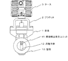
図6は、本発明の他の実施例の要部構成説明図である。
図6において、振動検出発生ユニット51は、3軸ジャイロ511と振動制御回路512と圧電アクチュエータ513と付加質量514とを有する。
3軸ジャイロ511は渦流量計のカルマン渦による交番圧力の変動を検出しない位置に設けられXYZ軸方向の振動ノイズをそれぞれ検出する。
例えば、本体1に設けられた柔軟な台の上に取付けられている。
FIG. 6 is an explanatory view of the main part configuration of another embodiment of the present invention.
In FIG. 6, the vibration detection generating unit 51 includes a three-axis gyro 511, a vibration control circuit 512, a piezoelectric actuator 513, and an additional mass 514.
The three-axis gyro 511 is provided at a position where the fluctuation of the alternating pressure due to the Karman vortex of the vortex flowmeter is not detected, and detects vibration noise in the XYZ axis directions.
For example, it is mounted on a flexible base provided in the main body 1.
振動制御回路512は、3軸ジャイロ511で検出された振動信号に基づき、このジャイロ検出振動信号と逆位相の振動信号を出力する。
圧電アクチュエータ513は、渦発生体12に設けられ、3軸ジャイロ511のXYZ軸に対応して一方の面が設けられ、振動制御回路512からの信号に基づき、ジャイロ検出振動信号を打ち消す振動を発生する。
付加質量514は、この圧電アクチュエータ513の他方の面にそれぞれ一面が設けられている。
The vibration control circuit 512 outputs a vibration signal having a phase opposite to that of the gyro detection vibration signal based on the vibration signal detected by the three-axis gyro 511.
The piezoelectric actuator 513 is provided on the
One surface of the additional mass 514 is provided on the other surface of the piezoelectric actuator 513.
以上の構成において、図6に示すように、3軸ジャイロ511を渦流量計のカルマン渦による交番圧力の変動を検出しない位置に取り付ける。
圧電アクチュエータ513と付加質量514とを、渦発生体12に取り付ける。
渦流量計の振動を3軸ジャイロ411で検出し、検出したそれぞれの軸方向振動に対し、振動制御回路412からの信号に基づき、逆位相で圧電アクチュエータ413を振動させ渦流量計の振動を減衰させる。
In the above configuration, as shown in FIG. 6, the three-axis gyro 511 is attached at a position where the fluctuation of the alternating pressure due to the Karman vortex of the vortex flowmeter is not detected.
A piezoelectric actuator 513 and an additional mass 514 are attached to the
The vibration of the vortex flowmeter is detected by the three-axis gyro 411, and the vibration of the vortex flowmeter is attenuated by oscillating the piezoelectric actuator 413 in the opposite phase based on the signal from the vibration control circuit 412 for each detected axial vibration. Let
この結果、
ケース3の振動によるノイズ成分だけでなく、渦発生体12の自重により生じる振動ノイズもキャンセルすることができる。
全周波数帯域で耐振性を向上出来る渦流量計が得られる。
As a result,
Not only the noise component due to the vibration of the
A vortex flowmeter that can improve vibration resistance in all frequency bands can be obtained.
なお、以上の説明は、本発明の説明および例示を目的として特定の好適な実施例を示したに過ぎない。
したがって本発明は、上記実施例に限定されることなく、その本質から逸脱しない範囲で更に多くの変更、変形をも含むものである。
The above description merely shows a specific preferred embodiment for the purpose of explanation and illustration of the present invention.
Therefore, the present invention is not limited to the above-described embodiments, and includes many changes and modifications without departing from the essence thereof.
1 本体
2 ブラケット
3 ケース
FL 測定流体
10 管路
11 ノズル
12 渦発生体
13 ネジ
14 フランジ部
15 凹部
16 第1コモン電極
17 圧電素子
18 電極板
19 絶縁板
20 電極板
21 圧電素子
22 押圧棒
23 リード線
24 リード線
25 電荷増幅器
26 電荷増幅器
27 ボリウム
28 加算器
31 振動検出発生ユニット
311 3軸ジャイロ
312 振動制御回路
313 圧電アクチュエータ
314 付加質量
41 振動検出発生ユニット
411 3軸ジャイロ
412 振動制御回路
413 圧電アクチュエータ
414 付加質量
51 振動検出発生ユニット
511 3軸ジャイロ
512 振動制御回路
513 圧電アクチュエータ
514 付加質量
FL 測定流体
DESCRIPTION OF SYMBOLS 1
Claims (3)
前記ケースに設けられXYZ軸方向のケース振動のノイズをそれぞれ検出する3軸ジャイロと、
この3軸ジャイロで検出された振動信号に基づきこのジャイロ検出振動信号と逆位相の振動信号を出力する振動制御回路と、
前記3軸ジャイロのケースに前記XYZ軸に直交してそれぞれ一方の面が設けられ前記振動制御回路からの信号に基づき前記ジャイロ検出振動信号を打ち消す振動を発生する圧電アクチュエータと、
この圧電アクチュエータの他方の面にそれぞれ一面が設けられた付加質量と
を有する振動検出発生ユニット
を具備したことを特徴とする渦流量計。 In a vortex flowmeter that has a case attached to the main body of the pipe and detects a change in alternating pressure due to Karman vortex by a stress detection element provided in the vortex generator to measure a flow velocity flow rate,
A three-axis gyro provided on the case for detecting noise in case vibrations in the XYZ-axis directions;
A vibration control circuit for outputting a vibration signal having a phase opposite to that of the gyro detection vibration signal based on the vibration signal detected by the three-axis gyro;
A piezoelectric actuator for generating a vibration that cancels the gyro detection vibration signal based on a signal from the vibration control circuit, each of which is provided on one side of the triaxial gyro case at right angles to the XYZ axes;
A vortex flowmeter comprising: a vibration detection and generation unit having an additional mass each having one surface provided on the other surface of the piezoelectric actuator.
前記渦発生体に設けられXYZ軸方向の振動ノイズをそれぞれ検出する3軸ジャイロと、
この3軸ジャイロで検出された振動信号に基づきこのジャイロ検出振動信号と逆位相の振動信号を出力する振動制御回路と、
前記3軸ジャイロのケースに前記XYZ軸に直交してそれぞれ一方の面が設けられ前記振動制御回路からの信号に基づき前記ジャイロ検出振動信号を打ち消す振動を発生する圧電アクチュエータと、
この圧電アクチュエータの他方の面にそれぞれ一面が設けられた付加質量と
を有する振動検出発生ユニット
を具備したことを特徴とする渦流量計。 In a vortex flowmeter that has a case attached to the main body of the pipe and detects a change in alternating pressure due to Karman vortex by a stress detection element provided in the vortex generator to measure a flow velocity flow rate,
A three-axis gyro provided on the vortex generator for detecting vibration noise in the XYZ-axis directions;
A vibration control circuit for outputting a vibration signal having a phase opposite to that of the gyro detection vibration signal based on the vibration signal detected by the three-axis gyro;
A piezoelectric actuator for generating a vibration that cancels the gyro detection vibration signal based on a signal from the vibration control circuit, each of which is provided on one side of the triaxial gyro case at right angles to the XYZ axes;
A vortex flowmeter comprising: a vibration detection and generation unit having an additional mass each having one surface provided on the other surface of the piezoelectric actuator.
前記渦流量計の前記カルマン渦による交番圧力の変動を検出しない位置に設けられXYZ軸方向の振動ノイズをそれぞれ検出する3軸ジャイロと、
この3軸ジャイロで検出された振動信号に基づきこのジャイロ検出振動信号と逆位相の振動信号を出力する振動制御回路と、
前記渦発生体に設けられ前記3軸ジャイロの前記XYZ軸に対応して一方の面が設けられ前記振動制御回路からの信号に基づき前記ジャイロ検出振動信号を打ち消す振動を発生する圧電アクチュエータと、
この圧電アクチュエータの他方の面にそれぞれ一面が設けられた付加質量と
を有する振動検出発生ユニット
を具備したことを特徴とする渦流量計。 In a vortex flowmeter that has a case attached to the main body of the pipe and detects a change in alternating pressure due to Karman vortex by a stress detection element provided in the vortex generator to measure a flow velocity flow rate,
A three-axis gyro provided at a position where the fluctuation of the alternating pressure due to the Karman vortex of the vortex flowmeter is not detected, and detecting vibration noise in the XYZ-axis directions,
A vibration control circuit for outputting a vibration signal having a phase opposite to that of the gyro detection vibration signal based on the vibration signal detected by the three-axis gyro;
A piezoelectric actuator that is provided on the vortex generator and has one surface corresponding to the XYZ axes of the three-axis gyro, and generates a vibration that cancels the gyro detection vibration signal based on a signal from the vibration control circuit;
A vortex flowmeter comprising: a vibration detection and generation unit having an additional mass each having one surface provided on the other surface of the piezoelectric actuator.
Priority Applications (1)
| Application Number | Priority Date | Filing Date | Title |
|---|---|---|---|
| JP2009262943A JP5423963B2 (en) | 2009-11-18 | 2009-11-18 | Vortex flow meter |
Applications Claiming Priority (1)
| Application Number | Priority Date | Filing Date | Title |
|---|---|---|---|
| JP2009262943A JP5423963B2 (en) | 2009-11-18 | 2009-11-18 | Vortex flow meter |
Publications (2)
| Publication Number | Publication Date |
|---|---|
| JP2011106989A true JP2011106989A (en) | 2011-06-02 |
| JP5423963B2 JP5423963B2 (en) | 2014-02-19 |
Family
ID=44230633
Family Applications (1)
| Application Number | Title | Priority Date | Filing Date |
|---|---|---|---|
| JP2009262943A Expired - Fee Related JP5423963B2 (en) | 2009-11-18 | 2009-11-18 | Vortex flow meter |
Country Status (1)
| Country | Link |
|---|---|
| JP (1) | JP5423963B2 (en) |
Cited By (1)
| Publication number | Priority date | Publication date | Assignee | Title |
|---|---|---|---|---|
| EP2482041A1 (en) * | 2011-01-31 | 2012-08-01 | KROHNE Messtechnik GmbH | Vortex flow rate measurement device |
Families Citing this family (1)
| Publication number | Priority date | Publication date | Assignee | Title |
|---|---|---|---|---|
| JPH0712602B2 (en) | 1989-06-08 | 1995-02-15 | 永大産業株式会社 | Veneer |
Citations (2)
| Publication number | Priority date | Publication date | Assignee | Title |
|---|---|---|---|---|
| JPH11258016A (en) * | 1998-03-13 | 1999-09-24 | Yokogawa Electric Corp | Vortex flow meter |
| JP2003322553A (en) * | 2002-05-07 | 2003-11-14 | Yokogawa Electric Corp | Vortex flow meter |
-
2009
- 2009-11-18 JP JP2009262943A patent/JP5423963B2/en not_active Expired - Fee Related
Patent Citations (2)
| Publication number | Priority date | Publication date | Assignee | Title |
|---|---|---|---|---|
| JPH11258016A (en) * | 1998-03-13 | 1999-09-24 | Yokogawa Electric Corp | Vortex flow meter |
| JP2003322553A (en) * | 2002-05-07 | 2003-11-14 | Yokogawa Electric Corp | Vortex flow meter |
Cited By (3)
| Publication number | Priority date | Publication date | Assignee | Title |
|---|---|---|---|---|
| EP2482041A1 (en) * | 2011-01-31 | 2012-08-01 | KROHNE Messtechnik GmbH | Vortex flow rate measurement device |
| JP2012159508A (en) * | 2011-01-31 | 2012-08-23 | Krohne Messtechnik Gmbh | Vortex flowmeter |
| US8820176B2 (en) | 2011-01-31 | 2014-09-02 | Krohne Messtechnik Gmbh | Vortex flow meter having an inertial sensor for detecting parasitic oscillations |
Also Published As
| Publication number | Publication date |
|---|---|
| JP5423963B2 (en) | 2014-02-19 |
Similar Documents
| Publication | Publication Date | Title |
|---|---|---|
| US8695439B2 (en) | Dual pick-off vibratory flowmeter | |
| CN101162237A (en) | Acceleration sensor | |
| US4437350A (en) | Vortex flow metering apparatus | |
| JP3565588B2 (en) | Vibration type measuring instrument | |
| JP5423963B2 (en) | Vortex flow meter | |
| JP2005221251A (en) | Coriolis flow meter | |
| JP3629703B2 (en) | Vortex flow meter | |
| JP2015184175A (en) | Current sensor and current sensor set | |
| JPS58160813A (en) | Vortex flow meter | |
| JP2005221380A (en) | Coriolis flow meter | |
| JP4089895B2 (en) | Vortex flow meter | |
| JP5165879B2 (en) | Angular velocity sensor | |
| JP4670152B2 (en) | Vortex flow meter | |
| JPH11258016A (en) | Vortex flow meter | |
| JPH11295118A (en) | Vortex flow meter | |
| CN118583231B (en) | Flow rate detection device and flow rate detection method | |
| JP3002778B1 (en) | Karman vortex ultrasonic flow meter device | |
| JP7328832B2 (en) | coriolis flow meter | |
| JPH11248500A (en) | Vortex flow meter | |
| JPH10246657A (en) | Vortex flow meter | |
| JP5522351B2 (en) | Physical quantity sensor | |
| JPS6047531B2 (en) | vortex flow meter | |
| JPS6046368B2 (en) | vortex flow meter | |
| JPH11248501A (en) | Vortex flow meter | |
| JP2003322553A (en) | Vortex flow meter |
Legal Events
| Date | Code | Title | Description |
|---|---|---|---|
| A621 | Written request for application examination |
Free format text: JAPANESE INTERMEDIATE CODE: A621 Effective date: 20120810 |
|
| TRDD | Decision of grant or rejection written | ||
| A01 | Written decision to grant a patent or to grant a registration (utility model) |
Free format text: JAPANESE INTERMEDIATE CODE: A01 Effective date: 20131030 |
|
| A61 | First payment of annual fees (during grant procedure) |
Free format text: JAPANESE INTERMEDIATE CODE: A61 Effective date: 20131112 |
|
| R150 | Certificate of patent or registration of utility model |
Free format text: JAPANESE INTERMEDIATE CODE: R150 Ref document number: 5423963 Country of ref document: JP Free format text: JAPANESE INTERMEDIATE CODE: R150 |
|
| LAPS | Cancellation because of no payment of annual fees |