JP2011106971A - Rebar pull-out test equipment - Google Patents
Rebar pull-out test equipment Download PDFInfo
- Publication number
- JP2011106971A JP2011106971A JP2009262424A JP2009262424A JP2011106971A JP 2011106971 A JP2011106971 A JP 2011106971A JP 2009262424 A JP2009262424 A JP 2009262424A JP 2009262424 A JP2009262424 A JP 2009262424A JP 2011106971 A JP2011106971 A JP 2011106971A
- Authority
- JP
- Japan
- Prior art keywords
- reinforcing bar
- taper
- frame
- reinforcing
- main body
- Prior art date
- Legal status (The legal status is an assumption and is not a legal conclusion. Google has not performed a legal analysis and makes no representation as to the accuracy of the status listed.)
- Pending
Links
- 238000007586 pull-out test Methods 0.000 title claims abstract description 25
- 230000003014 reinforcing effect Effects 0.000 claims abstract description 85
- 238000010621 bar drawing Methods 0.000 description 3
- 238000003780 insertion Methods 0.000 description 2
- 230000037431 insertion Effects 0.000 description 2
- 239000002184 metal Substances 0.000 description 2
- 238000000605 extraction Methods 0.000 description 1
- 238000005259 measurement Methods 0.000 description 1
- 238000000034 method Methods 0.000 description 1
- 230000002093 peripheral effect Effects 0.000 description 1
Images

Landscapes
- Investigating Strength Of Materials By Application Of Mechanical Stress (AREA)
Abstract
Description
本発明は、コンクリートに埋設された鉄筋の引抜耐力試験に使用される鉄筋引抜試験装置に関する。 The present invention relates to a reinforcing bar drawing test apparatus used for a pulling strength test of reinforcing bars embedded in concrete.
コンクリートに埋設された鉄筋の引抜耐力試験に使用される鉄筋引抜試験装置としては、例えば特許文献1に記載された鉄筋引き抜き試験装置がある。
特許文献1に記載された鉄筋引き抜き試験装置は、二つ割りしたブロックの併合面に直交する面が垂直面で、かつ、対向する面が下方から上方にかけて開拡する一定の曲率をもつ曲面である鉄筋挿通孔を形成した引き抜き治具と、引き抜き治具の鉄筋挿通孔の垂直面と一定の曲率をもつ曲面に沿った形状のくさびと、引き抜き治具を加圧するジャッキ装置とからなることを特徴とするものである(特許文献1の請求項1参照)。
As a reinforcing bar drawing test apparatus used for a pulling strength test of reinforcing bars embedded in concrete, there is a reinforcing bar pulling test apparatus described in Patent Document 1, for example.
The rebar pull-out test apparatus described in Patent Document 1 is a rebar whose surface perpendicular to the merged surface of the two divided blocks is a vertical surface and whose opposite surface is a curved surface having a certain curvature that expands from below to above. A drawing jig having an insertion hole, a wedge shaped along a curved surface having a certain curvature and a vertical surface of a reinforcing bar insertion hole of the drawing jig, and a jack device that pressurizes the drawing jig. (See claim 1 of Patent Document 1).
鉄筋を引抜く際、上記鉄筋引き抜き試験装置においては、U字状の開口部を有する反力部材に鉄筋を挿入するようにして前記反力部材をコンクリート上に設置し、その上に2本のジャッキをシリンダを上に向けて設置する。そして、シリンダ上端部に加圧部材を設置し、該加圧部材の上面に鉄筋をチャックした引き抜き治具の下面を当接させる。このように配置して、ジャッキのシリンダを伸張させることで、加圧部材を介して引き抜き治具を押し上げ、鉄筋に引抜力を与えるようにしていうる(特許文献1の図1参照)。 When pulling out a reinforcing bar, in the reinforcing bar pull-out test apparatus, the reaction force member is installed on the concrete so that the reinforcing bar is inserted into the reaction force member having a U-shaped opening, and two pieces of the reaction force member are placed thereon. Install the jack with the cylinder facing up. And a pressurizing member is installed in the cylinder upper end part, and the lower surface of the extraction jig | tool which chucked the reinforcing bar is contact | abutted on the upper surface of this pressurizing member. By arranging the jack cylinder in this way and extending the jack, the pulling jig can be pushed up via the pressure member to give a pulling force to the reinforcing bar (see FIG. 1 of Patent Document 1).
特許文献1に記載の鉄筋引き抜き試験装置においては、鉄筋をチャックした引き抜き治具をこれの下方に配置したジャッキで押し上げるようにしているため、鉄筋をチャックした引き抜き治具の下方に反力部材、ジャッキ、および加圧部材を配置するスペースが必要となる。そのため、コンクリートから延出する鉄筋の長さが短い場合には適用できないという問題がある。 In the reinforcing bar pull-out test apparatus described in Patent Document 1, the pulling jig that chucks the reinforcing bar is pushed up by the jack arranged below the reaction jig, so that the reaction force member is located below the pulling jig that chucked the reinforcing bar, A space for arranging the jack and the pressure member is required. Therefore, there exists a problem that it cannot apply when the length of the reinforcing bar extended from concrete is short.
本発明はかかる課題を解決するためになされたものであり、コンクリート上に延出する鉄筋長さが短い場合であっても鉄筋をチャックして引抜試験を行うことのできる鉄筋引抜試験装置を提供することを目的としている。 The present invention has been made to solve such a problem, and provides a rebar pull-out test apparatus capable of chucking a rebar and performing a pull-out test even when the length of the rebar extending on concrete is short. The purpose is to do.
(1)本発明に係る鉄筋引抜試験装置は、先端側に反力部材を設けたロッドと、該ロッドが伸縮可能に収容されるシリンダ部を内蔵する本体部とを有する油圧ジャッキを一対備え、該一対の油圧ジャッキの各ジャッキが前記本体部側面を対向させて所定間隔離して配置され、引抜対象となる鉄筋を把持する鉄筋把持部材を前記各本体部の対向側面におけるロッド寄りの部位に設けてなることを特徴とするものである。 (1) A reinforcing bar pull-out test apparatus according to the present invention includes a pair of hydraulic jacks each having a rod provided with a reaction force member on a distal end side and a main body portion containing a cylinder portion in which the rod is accommodated so as to be expandable and contractible. Respective jacks of the pair of hydraulic jacks are arranged with a predetermined distance from each other with the side faces of the main body facing each other, and a reinforcing bar gripping member for gripping a reinforcing bar to be pulled out is provided at a position near the rod on the opposite side face of each main body. It is characterized by.
(2)また、上記(1)に記載のものにおいて、前記鉄筋把持部材は、各本体部側面に取り付けられ、内面がテーパ状に形成された半割りのテーパ枠と、該半割りのテーパ枠を枠体として一体化するテーパ枠固定具と、前記テーパ枠内に設置されて引抜対象となる鉄筋を把持するテーパ状の鉄筋把持具とを備えてなることを特徴とするものである。 (2) Further, in the above (1), the reinforcing bar gripping member is attached to the side surface of each main body part, and the half taper frame having an inner surface formed in a taper shape, and the half taper frame And a taper frame fixing tool that is installed in the taper frame and grips a reinforcing bar to be pulled out.
(3)また、上記(1)または(2)に記載のものにおいて、試験対象の鉄筋を跨ぐことができる荷重計測装置を前記一対のジャッキの両方の反力部材に亘るように設置したことを特徴とするものである。 (3) Moreover, in the thing as described in said (1) or (2), having installed the load measuring device which can straddle the reinforcing bar of a test object so that it may span over both reaction force members of a pair of said jack. It is a feature.
本発明においては、先端側に反力部材を設けたロッドと、該ロッドが伸縮可能に収容されるシリンダ部を内蔵する本体部とを有する油圧ジャッキを一対備え、該一対の油圧ジャッキの各ジャッキが前記本体部側面を対向させて所定間隔離して配置され、引抜対象となる鉄筋を把持する鉄筋把持部を前記各本体部の対向側面におけるロッド寄りの部位に設けてなるので、鉄筋を把持するために必要な鉄筋の長さが短くてよく、種々の鉄筋を対象として引抜試験を行うことができる。 The present invention includes a pair of hydraulic jacks each having a rod provided with a reaction force member on the distal end side, and a main body portion containing a cylinder portion in which the rod is accommodated so as to be expandable and contractible, and each jack of the pair of hydraulic jacks Is arranged with the main body side face facing each other and separated by a predetermined distance, and a reinforcing bar gripping part for gripping the reinforcing bar to be pulled out is provided at a position near the rod on the opposing side face of each main body part. Therefore, the length of the reinforcing bars required for this purpose may be short, and a pull-out test can be performed on various reinforcing bars.
[実施の形態1]
本実施の形態に係る鉄筋引抜試験装置を図1乃至図7に基づいて説明する。
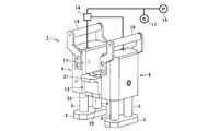
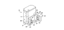
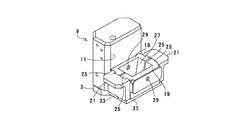
本実施の形態に係る鉄筋引抜試験装置1は、先端側に反力部材3を設けたロッド5と、該ロッド5が伸縮可能に収容されるシリンダ部(図示なし)を有する本体部7とを有する油圧ジャッキ9を一対有し、該一対の油圧ジャッキ9が前記本体部側面11を対向させて所定間隔離して配置され、前記各本体部7の対向側面に引抜対象となる鉄筋を把持する鉄筋把持部材13を備えてなるものである。
以下、各構成を詳細に説明する。
[Embodiment 1]
A reinforcing bar pull-out test apparatus according to the present embodiment will be described with reference to FIGS.
The reinforcing bar pull-out test apparatus 1 according to the present embodiment includes a
Hereinafter, each configuration will be described in detail.
<油圧ジャッキ>
本実施の形態においては、2台の油圧ジャッキ9を一対として使用し、図1、図2に示すように、鉄筋把持部材13が設けられた側面を対向させて配置される。各油圧ジャッキ9は、2本のロッド5を有し、該2本のロッド5に共通する反力部材3がロッド5先端に設置されている。油圧ポンプ15から送られる圧油は分岐金具14によって分岐され、各油圧ジャッキ9に送られて各ロッド5が伸縮するように構成されている。ロッド5に作用する引抜き荷重は油圧計17によって測定することができる。
各油圧ジャッキ9は、本体部7の上方に延出するハンドル18を有している(図1、図2参照)。
<Hydraulic jack>
In this embodiment, two
Each
<鉄筋把持部>
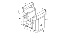
鉄筋把持部は、各本体部側面11に取り付けられた半割りのテーパ枠19と、該半割りのテーパ枠19を枠体として一体化するテーパ枠固定具21と、前記テーパ枠内に設置されて引抜対象となる鉄筋を把持する鉄筋把持具23(図6参照)とを備えている。
半割りのテーパ枠19は、図3、図4に示されるように、平面視で略コ字状をしており、コ字の向かい合う両片に外方に突出するフランジ部25を有している。コ字の向かい合う両片部が上面から下面に向かって中心側に傾斜する傾斜面27になっており、つまり、向かい合う両片部がテーパになっている。
<Rebar gripper>
The reinforcing bar gripping part is installed in the
As shown in FIGS. 3 and 4, the half-
テーパ枠19は、各本体部側面11におけるロッド寄りの部位に設けられており、それ故に引抜対象の鉄筋のコンクリートからの延出長さが短くても把持することが可能になっている。
テーパ枠19は本体部7の側面にネジ固定されるため、テーパ枠19には固定用のネジ穴29が設けられている(図3、図4、図5参照)。テーパ枠19の下面には中央に半円の切り欠き部31を有する位置決め用の位置決め板33が設置されている。位置決め板33の半円状の切り欠き部31を引抜き対象となる鉄筋に位置合わせすることで、ジャッキの鉄筋に対する位置合わせができるようになっている。位置決め板33はテーパ枠19にボルト35によって固定されている(図4参照)。
一方のテーパ枠19のコ字の両片側端面には、凸部37が設けられ、他方のテーパ枠19には前記凸部37に対向する位置に凸部37が挿入可能な凹部(図示なし)が設けられている。凸部37を凹部に嵌合させることで、一対のジャッキの位置合わせができるようになっている。
The
Since the
一対の半割りのテーパ枠19の対向面を当接させた状態で、各テーパ枠19のフランジ部25が離れないように一体化するテーパ枠固定具21が設けられる。テーパ枠固定具21には、フランジ部25が挿入される溝部39が設けられており、該溝部39にフランジ部25が挿入されることで半割りのテーパ枠19を一体化する(図3、図4参照)。
A
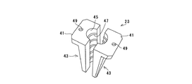
テーパ枠19内には、引抜対象となる鉄筋を把持するテーパ状の鉄筋把持具23が設置される。鉄筋把持具23としては、市販のものを使用することができ、図6はその一例を示している。鉄筋把持具23は、上部にフランジ41を有し、側面がテーパ枠19のテーパの傾斜面27に沿う傾斜面27になっている一対の半割り部材43から構成されている。各半割り部材43の中心部には半円筒状の凹溝45が形成され、該凹溝45の内周面には周方向に延びる突条47が複数設けられている。
フランジ41には鉄筋把持具23を取り外すときに取り外し用のボルトを螺入するためのボルト穴49が形成されている。鉄筋把持具23は、テーパ枠19内に設置され、テーパ枠19を押し上げることにより、図7に示すように、テーパ枠19内に押し込まれ、引抜対象の鉄筋をより強く把持する構造になっている。
In the
The
次に、上記のように構成された本実施の形態の鉄筋引抜き装置の使用方法について説明する。
片側のジャッキを、位置決め板33の切り欠き部31内に引抜対象の鉄筋が位置するように配置する(図3参照)。そして、対向側のジャッキを、同じく切り欠き部31に鉄筋が位置するように配置すると共に、テーパ枠19の凹部と凸部37を嵌合させる。そして、テーパ固定具をテーパ枠19に設置してテーパ枠19を一体化する。
テーパ枠19が一体化されると、鉄筋把持具23をテーパ枠19内に、鉄筋を把持させるように設置する。
Next, a method for using the reinforcing bar drawing device according to the present embodiment configured as described above will be described.
The jack on one side is arranged so that the reinforcing bar to be pulled out is positioned in the
When the
この状態で油圧ジャッキ9を駆動してロッド5を伸張させると、鉄筋把持具23はテーパ枠19に押し込まれ、それによって鉄筋把持具23を構成する半割り部材43が押し縮められて鉄筋を強固に把持する。この状態でさらにロッド5を伸ばすことで、鉄筋に引抜き力が付加され、そのときの油圧が計測されて、鉄筋の引抜耐力が測定される。
試験後に鉄筋把持具23をテーパ枠19から外す際には、鉄筋把持具23のフランジ41に設けたボルト穴49にボルトを螺入することで、鉄筋把持具23をテーパ枠19から離隔させることができ、容易に外すことができる。
When the
When removing the reinforcing
以上のように、本実施の形態においては、半割りのテーパ枠19を本体部側面11におけるロッド寄りの部位に設置したので、鉄筋を把持するために必要な鉄筋の長さが短くてよく、種々の鉄筋を対象として実際の計測ができる。
また、鉄筋を把持するためのテーパ枠19が半割りになっているので、鉄筋に枠体を挿通する必要がなく、鉄筋が極端に長い場合や、鉄筋の先端が湾曲している場合や、さらには鉄筋の先端が開放端となっていない閉端の場合のように枠体の挿入が困難な場合でも難なく適用できる。
As described above, in the present embodiment, the
In addition, since the
[実施の形態2]
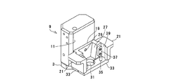
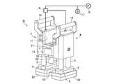
図8に基づいて実施の形態2に係る鉄筋引抜試験装置51を説明する。本実施の形態に係る鉄筋引抜試験装置51は、荷重測定装置であるロードセル52を一対のジャッキの両方の反力部材3に亘るように設置したものである。ロードセル52には、U字状の開口部53が設けられ、引抜き対象の鉄筋を側方から挿入できるようになっている。ロードセル52は反力部材3に磁石によって着脱可能に設置される。
ロードセル52を設けることによって、鉄筋引抜き耐力を正確にかつタイムリーに検出することができる。
つまり、油圧計17で鉄筋引抜き耐力を計測すると、ジャッキのシリンダの摺動抵抗や、配管内を油が流れるときの抵抗があるため、計測値が実際の鉄筋引抜き抵抗値よりも大きくなり、油圧計17そのままの値では誤差がでる。これをなくするには油の流れが落ち着くまで少し時間をおく必要がある。これに対して、ロードセル52を用いることにより、タイムリーに正確な引抜き耐力測定ができる。
[Embodiment 2]
Based on FIG. 8, the reinforcing bar pull-out
By providing the
That is, when the reinforcing bar pull-out strength is measured by the
1 鉄筋引抜試験装置
3 反力部材
5 ロッド
7 本体部
9 油圧ジャッキ
11 本体部側面
13 鉄筋把持部材
14 分岐金具
15 油圧ポンプ
17 油圧計
18 ハンドル
19 テーパ枠
21 テーパ枠固定具
23 鉄筋把持具
25 フランジ部
27 傾斜面
29 ネジ穴
31 切り欠き部
33 位置決め板
35 ボルト
37 凸部
39 溝部
41 フランジ
43 半割り部材
45 凹溝
47 突条
49 ボルト穴
51 鉄筋引抜試験装置
52 ロードセル
53 開口部
DESCRIPTION OF SYMBOLS 1 Rebar pull-out
Claims (3)
Priority Applications (1)
| Application Number | Priority Date | Filing Date | Title |
|---|---|---|---|
| JP2009262424A JP2011106971A (en) | 2009-11-18 | 2009-11-18 | Rebar pull-out test equipment |
Applications Claiming Priority (1)
| Application Number | Priority Date | Filing Date | Title |
|---|---|---|---|
| JP2009262424A JP2011106971A (en) | 2009-11-18 | 2009-11-18 | Rebar pull-out test equipment |
Publications (1)
| Publication Number | Publication Date |
|---|---|
| JP2011106971A true JP2011106971A (en) | 2011-06-02 |
Family
ID=44230617
Family Applications (1)
| Application Number | Title | Priority Date | Filing Date |
|---|---|---|---|
| JP2009262424A Pending JP2011106971A (en) | 2009-11-18 | 2009-11-18 | Rebar pull-out test equipment |
Country Status (1)
| Country | Link |
|---|---|
| JP (1) | JP2011106971A (en) |
Cited By (6)
| Publication number | Priority date | Publication date | Assignee | Title |
|---|---|---|---|---|
| CN108469378A (en) * | 2018-06-06 | 2018-08-31 | 重庆大学 | A kind of oblique pull-out test device of lever built-in fitting and its test method |
| CN111721612A (en) * | 2020-06-04 | 2020-09-29 | 河北建筑工程学院 | An anchor rod pull-out test device and test method considering the influence of temperature and pressure |
| CN117213825A (en) * | 2023-10-19 | 2023-12-12 | 重庆市建设工程质量检验测试中心有限公司 | An on-site in-situ testing device for the bearing capacity of steel bar connection joints |
| CN117309358A (en) * | 2023-10-19 | 2023-12-29 | 重庆市建设工程质量检验测试中心有限公司 | An on-site in-situ testing method for the bearing capacity of steel bar connection joints |
| JP7593342B2 (en) | 2022-01-21 | 2024-12-03 | 中国電力株式会社 | Pull-out Test Equipment |
| CN121207713A (en) * | 2025-11-28 | 2025-12-26 | 北京中鑫博海建设工程有限公司 | A field testing device for post-anchored steel bars |
-
2009
- 2009-11-18 JP JP2009262424A patent/JP2011106971A/en active Pending
Cited By (9)
| Publication number | Priority date | Publication date | Assignee | Title |
|---|---|---|---|---|
| CN108469378A (en) * | 2018-06-06 | 2018-08-31 | 重庆大学 | A kind of oblique pull-out test device of lever built-in fitting and its test method |
| CN108469378B (en) * | 2018-06-06 | 2024-01-09 | 重庆大学 | A lever-type embedded part oblique pull-out test device and its test method |
| CN111721612A (en) * | 2020-06-04 | 2020-09-29 | 河北建筑工程学院 | An anchor rod pull-out test device and test method considering the influence of temperature and pressure |
| CN111721612B (en) * | 2020-06-04 | 2023-11-24 | 河北建筑工程学院 | Anchor rod drawing test device and test method considering temperature and pressure influence |
| JP7593342B2 (en) | 2022-01-21 | 2024-12-03 | 中国電力株式会社 | Pull-out Test Equipment |
| CN117213825A (en) * | 2023-10-19 | 2023-12-12 | 重庆市建设工程质量检验测试中心有限公司 | An on-site in-situ testing device for the bearing capacity of steel bar connection joints |
| CN117309358A (en) * | 2023-10-19 | 2023-12-29 | 重庆市建设工程质量检验测试中心有限公司 | An on-site in-situ testing method for the bearing capacity of steel bar connection joints |
| CN121207713A (en) * | 2025-11-28 | 2025-12-26 | 北京中鑫博海建设工程有限公司 | A field testing device for post-anchored steel bars |
| CN121207713B (en) * | 2025-11-28 | 2026-02-24 | 北京中鑫博海建设工程有限公司 | A field testing device for post-anchored steel bars |
Similar Documents
| Publication | Publication Date | Title |
|---|---|---|
| JP2011106971A (en) | Rebar pull-out test equipment | |
| CN203929504U (en) | A detachable small sample tensile testing machine fixture | |
| CN102539253B (en) | Tester for measuring real stress-strain curve of plate material under unidirectional compression state | |
| EP2480362B1 (en) | Method and template for producing a tensile test coupon | |
| CN104792613A (en) | Rectangular pyramid concrete tensile specimen clamp | |
| CN106053217A (en) | Multifunctional T type sample stretching and fatigue experiment clamp | |
| CN106289977B (en) | A kind of bolt concrete tensile test device and test method | |
| CN102707097B (en) | With the testing wire clamp of magnetic-suction type connecting device | |
| CN203534877U (en) | Mould for preparing test piece for tensile test of concrete | |
| CN201181269Y (en) | Auxiliary clamping device for measuring sample elongation and area reduction | |
| CN207423710U (en) | A kind of irregular sample Vickers hardness test auxiliary tool | |
| CN104568532A (en) | Mould for preparing test piece used for concrete tensile test | |
| CN201100860Y (en) | Positioning device for axial tension test of brittle material specimens | |
| CN205879670U (en) | Quick release of vulcanite compression deformation test | |
| CN104819893B (en) | Hemispherical Concrete Tensile Specimen Fixture | |
| CN204705545U (en) | Cable checkout equipment fixture | |
| KR102212052B1 (en) | Multi-axis fatigue test jig constituting fatigue testing device | |
| CN103091161B (en) | Tensile strength test clamp for automatic positioning screw | |
| CN204575435U (en) | Semisphere Analysis of Concrete Tensile piece fixture | |
| RU153816U1 (en) | DEVICE FOR CORROSION TESTING SAMPLES | |
| JP2018178360A (en) | Stress introduction device for PC steel rod unit | |
| CN204479405U (en) | A kind of right cylinder test specimen splitting fatigue test fixture for UTM test instrument | |
| CN223115074U (en) | Track scale weighing sensor extracting tool | |
| JP7654439B2 (en) | Test piece gripping tool for tensile testing and tensile testing method | |
| CN213933431U (en) | A kind of mechanical anchor bolt shear test equipment |