JP2011106953A - Method for detecting battery capacity - Google Patents
Method for detecting battery capacity Download PDFInfo
- Publication number
- JP2011106953A JP2011106953A JP2009262017A JP2009262017A JP2011106953A JP 2011106953 A JP2011106953 A JP 2011106953A JP 2009262017 A JP2009262017 A JP 2009262017A JP 2009262017 A JP2009262017 A JP 2009262017A JP 2011106953 A JP2011106953 A JP 2011106953A
- Authority
- JP
- Japan
- Prior art keywords
- value
- battery
- predetermined
- timing
- battery capacity
- Prior art date
- Legal status (The legal status is an assumption and is not a legal conclusion. Google has not performed a legal analysis and makes no representation as to the accuracy of the status listed.)
- Pending
Links
Images


Classifications
-
- Y—GENERAL TAGGING OF NEW TECHNOLOGICAL DEVELOPMENTS; GENERAL TAGGING OF CROSS-SECTIONAL TECHNOLOGIES SPANNING OVER SEVERAL SECTIONS OF THE IPC; TECHNICAL SUBJECTS COVERED BY FORMER USPC CROSS-REFERENCE ART COLLECTIONS [XRACs] AND DIGESTS
- Y02—TECHNOLOGIES OR APPLICATIONS FOR MITIGATION OR ADAPTATION AGAINST CLIMATE CHANGE
- Y02E—REDUCTION OF GREENHOUSE GAS [GHG] EMISSIONS, RELATED TO ENERGY GENERATION, TRANSMISSION OR DISTRIBUTION
- Y02E60/00—Enabling technologies; Technologies with a potential or indirect contribution to GHG emissions mitigation
- Y02E60/10—Energy storage using batteries
Landscapes
- Tests Of Electric Status Of Batteries (AREA)
- Charge And Discharge Circuits For Batteries Or The Like (AREA)
- Secondary Cells (AREA)
Abstract
Description
本発明は、電池容量検出方法の技術に関する。 The present invention relates to a technique for a battery capacity detection method.
特許文献1では、以下の手順によってバッテリ容量を算出する満充電容量検出方法が開示されている。
1.第1の検出タイミングと、第2の検出タイミングとの間において、電池の充放電電流の積算値から充放電電気量を算出する。
2.第1の検出タイミングにおけるOCV(Open Circuit Voltage)と、第2のタイミングにおけるOCVを検出し、これらのOCVからバッテリのSOC(State Of Charge:電池の残容量)を算出する。
3.第1のタイミングおよび第2のタイミングにおけるSOCの変動値(ΔSOC)と、充放電電気量(ΣI)から下記の式(B1)よりバッテリ容量CAPAを算出する。
1. Between the first detection timing and the second detection timing, the charge / discharge amount of electricity is calculated from the integrated value of the charge / discharge current of the battery.
2. The OCV (Open Circuit Voltage) at the first detection timing and the OCV at the second timing are detected, and the SOC (State Of Charge) of the battery is calculated from these OCVs.
3. The battery capacity CAPA is calculated from the following equation (B1) from the SOC fluctuation value (ΔSOC) and the charge / discharge amount (ΣI) at the first timing and the second timing.
CAPA=ΔAh/ΔSOC ・・・(B1) CAPA = ΔAh / ΔSOC (B1)
しかしながら、特許文献1に記載の技術ではOCVの検出に、充放電電気量に対するOCV特性の関数またはマップなどを用いている。この方法では、バッテリの経時変化や温度変化などによる特性変化には対応することが困難であり、OCVの検出誤差が大きくなってしまう。この結果、バッテリ容量の推定精度が悪化してしまうという問題がある。
However, in the technique described in
そこで、本発明の課題は、高精度な電池の満充電容量を可能とする電池容量検出方法を提供することにある。 Accordingly, an object of the present invention is to provide a battery capacity detection method that enables a highly accurate full charge capacity of a battery.
前記課題を解決する本発明のうち請求項1に記載の発明は、第1の検出タイミングと、第2の検出タイミングとの間における電池の容量変化値、および等価回路モデル方式によって算出された電池の残容量の変化率からCAPA=ΔAh/ΔSOCに従って、電池の満充電容量を検出する電池容量検出装置による電池容量検出方法であって、前記第1の検出タイミングおよび前記第2の検出タイミングは、等価回路モデルによる電圧推定値と、電圧センサから取得される実電圧値との誤差が所定の誤差以下であり、電流センサから取得される実電流値が所定の電流値以下であり、所定期間内の実電流変動値が所定の電流変動値以下であり、所定期間内の実電圧変動値が所定の電圧変動値以下であり、温度センサから取得される電池温度が所定の電池温度以上であることを特徴とする。
ただし、CAPAは前記電池の満充電容量であり、ΔAhは前記第1の検出タイミングと、前記第2の検出タイミングとの間における前記電池の容量変化値であり、ΔSOCは第1の検出タイミングと、第2の検出タイミングとの間における等価回路モデル方式によって算出された電池の残容量の変化率である。
The invention according to
However, CAPA is the full charge capacity of the battery, ΔAh is the capacity change value of the battery between the first detection timing and the second detection timing, and ΔSOC is the first detection timing. The change rate of the remaining capacity of the battery calculated by the equivalent circuit model method between the second detection timing and the second detection timing.
請求項1に係る発明によれば、等価回路モデルのモデル化誤差が大きくなる条件を避けた状況で、等価回路モデルで算出されたSOCを用いた電池の満充電容量を算出できるため、電池の経時的変化に追従した精度の高い電池の満充電容量を検出することが可能となる。 According to the first aspect of the invention, since the full charge capacity of the battery using the SOC calculated by the equivalent circuit model can be calculated in a situation avoiding the condition that the modeling error of the equivalent circuit model becomes large, It becomes possible to detect the full charge capacity of the battery with high accuracy following the change with time.
また、請求項2に係る発明は、前記所定の電流値が、前記所定の電流値以下、かつ、前記所定の電流値よりも低い第2の所定の電流値以上であることを特徴とする。 The invention according to claim 2 is characterized in that the predetermined current value is not more than the predetermined current value and not less than a second predetermined current value lower than the predetermined current value.
請求項2に係る発明によれば、電流値を所定の範囲内に収めることができるため、より精度の高い電池の満充電容量を検出することが可能となる。 According to the second aspect of the present invention, since the current value can be kept within a predetermined range, it is possible to detect the full charge capacity of the battery with higher accuracy.
また、請求項3に係る発明において、前記満充電容量は、CAPA(n)=W×CAPA(n−1)+(1−W)×(ΔAh/ΔSOC)によって補正されることを特徴とする。
ここで、CAPA(n)は前記満充電容量の今回値、CAPA(n−1)は前記満充電容量の前回値、Wは0≦W≦1の値をとる重み係数である。
In the invention according to claim 3, the full charge capacity is corrected by CAPA (n) = W × CAPA (n−1) + (1−W) × (ΔAh / ΔSOC). .
Here, CAPA (n) is a current value of the full charge capacity, CAPA (n−1) is a previous value of the full charge capacity, and W is a weighting coefficient that takes a value of 0 ≦ W ≦ 1.
請求項3に係る発明によれば、センサの誤差などに起因する算出満充電容量の急激な変化を防止することができる。 According to the third aspect of the present invention, it is possible to prevent a sudden change in the calculated full charge capacity due to a sensor error or the like.
そして、請求項4に係る発明において、CAPA(n)=W×CAPA(n−1)+(1−W)×(ΔAh/ΔSOC)によって算出される前記満充電容量は、CAPAF(n)=F×CAPA(n)+(1−F)×CAPAF(n−1)によって補正されることを特徴とする。
ここで、CAPAF(n)は満充電容量フィルタ値の今回値、CAPAF(n−1)は満充電容量フィルタ値の前回値、Fは0≦F≦1の値をとるフィルタ係数である。
In the invention according to claim 4, the full charge capacity calculated by CAPA (n) = W × CAPA (n−1) + (1−W) × (ΔAh / ΔSOC) is CAPAF (n) = It is corrected by F × CAPA (n) + (1−F) × CAPAF (n−1).
Here, CAPAF (n) is the current value of the full charge capacity filter value, CAPAF (n−1) is the previous value of the full charge capacity filter value, and F is a filter coefficient that takes a value of 0 ≦ F ≦ 1.
請求項4に係る発明によれば、電池の満充電容量の急激な変化を防止することができる。 According to the invention which concerns on Claim 4, the rapid change of the full charge capacity of a battery can be prevented.
本発明によれば、高精度な電池の満充電容量を可能とする電池容量検出方法を提供することができる。 ADVANTAGE OF THE INVENTION According to this invention, the battery capacity detection method which enables the full charge capacity of a highly accurate battery can be provided.
次に、本発明を実施するための最良の形態(「実施形態」という)について、適宜図面を参照しながら詳細に説明する。 Next, the best mode for carrying out the present invention (referred to as “embodiment”) will be described in detail with reference to the drawings as appropriate.
(バッテリ容量算出装置)
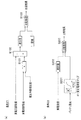
図1は、本実施形態に係るバッテリ容量算出装置の構成例を示すブロック図である。
バッテリ容量算出装置(電池容量検出装置)1は、等価回路モデル演算部10と、タイミング条件判定部20と、バッテリ容量演算部30と、記憶部40とを有している。
等価回路モデル演算部10は、車両に搭載される図示しないバッテリ(電池)に設置されている電圧センサ60、電流センサ70、温度センサ80から得られる実電圧値、実電流値、バッテリ温度の各センサ値が入力され、これらの値から等価回路モデル方式によるSOC推定値を算出し、算出したSOC推定値をバッテリ容量演算部30へ出力する機能を有する。
(Battery capacity calculation device)
FIG. 1 is a block diagram illustrating a configuration example of the battery capacity calculation apparatus according to the present embodiment.
The battery capacity calculation device (battery capacity detection device) 1 includes an equivalent circuit
The equivalent circuit
タイミング条件判定部20は、各センサ60,70、80から入力される実電圧値、実電流値、バッテリ温度や、記憶部40に記憶されている安定電流値マップ41、安定電流変動値マップ42、安定電圧変動値マップ43、基準抵抗値マップ44を用いて、以下の5つの条件(タイミング条件)のすべてが満たされているか否かを判定し、判定の結果にしたがって切替フラグをバッテリ容量演算部30へ出力する機能を有する。
The timing
条件Z1:等価回路モデル方式で推定された電圧変動値の推定値と、電圧センサ60から入力された実電圧変動値の差分値閾値(所定の誤差)以下
条件Z2:電流センサ70から入力された実電流値が所定上限値(所定の電流値)以下、もしくは実電流値が所定範囲(所定の下限電流値以上、所定の上限電流値以下)内
条件Z3:所定期間内における実電流変動値が所定値(所定の電流変動値)以下
条件Z4:所定期間内における実電圧変動値が所定値(所定の電圧変動値)以下
条件Z5:温度センサ80から入力されたバッテリ温度が閾値(所定の電池温度)以上
Condition Z1: Less than the difference value threshold (predetermined error) between the estimated value of the voltage fluctuation value estimated by the equivalent circuit model method and the actual voltage fluctuation value input from the voltage sensor 60 Condition Z2: input from the current sensor 70 The actual current value is less than or equal to a predetermined upper limit value (predetermined current value), or the actual current value is within a predetermined range (greater than or equal to a predetermined lower limit current value and less than or equal to a predetermined upper limit current value). Condition Z3: Condition Z4 below predetermined value (predetermined current fluctuation value): Actual voltage fluctuation value within predetermined period is below predetermined value (predetermined voltage fluctuation value) Condition Z5: Battery temperature input from
バッテリ容量演算部30は、タイミング条件Z1〜Z5の成立を検知すると、これを第1のタイミングまたは第2のタイミングとして等価回路モデルを用いて推定したSOC推定値を基に、バッテリ容量を算出する機能を有する。なお、バッテリ容量演算部30は、条件Z1〜Z5の成立に加えて、以下の条件(容量算出条件)W1〜W4が成立したときに、バッテリ容量を算出する。
条件W1:第1のタイミングと、第2のタイミングでのSOCの変動値(ΔSOC)が所定値以上(後記する式(5)の第2項における分母を小さくしないための条件)
条件W2:第1のタイミングと、第2のタイミング間で積算された実電流値(ΔAh=|ΣI|)が所定値以上(例えば、ΔAhが0に近い値である場合、後記する式(5)の第2項で算出されるバッテリ容量の今回値が0に近い値となってしまうのを避けるための条件)
条件W3:第1のタイミングと、第2のタイミングの間隔が所定時間T1以上、所定時間T2以下(短い時間でバッテリ容量の算出が行われないようにするためと、長期間にわたって実電流値が積算されるために生じるΔAhの誤差を避けるための条件)
条件W4:ΔSOCと、ΔAhの正負が同符号(本来同符号であるはずのΔSOCとΔAhが、異符号となっているときは電流センサ70などの誤差が生じていると考えられるため)
When the battery
Condition W1: The SOC fluctuation value (ΔSOC) at the first timing and the second timing is equal to or greater than a predetermined value (a condition for not reducing the denominator in the second term of Equation (5) described later).
Condition W2: When the actual current value (ΔAh = | ΣI |) integrated between the first timing and the second timing is equal to or larger than a predetermined value (for example, ΔAh is a value close to 0, the following formula (5 The condition for avoiding that the current value of the battery capacity calculated in the second term of) is close to 0)
Condition W3: The interval between the first timing and the second timing is not less than the predetermined time T1 and not more than the predetermined time T2 (in order to prevent the battery capacity from being calculated in a short time, the actual current value is (Conditions for avoiding the error of ΔAh caused by integration)
Condition W4: ΔSOC and the sign of ΔAh have the same sign (since ΔSOC and ΔAh, which should be the same sign originally, have different signs, it is considered that an error such as current sensor 70 has occurred)
これらの条件W1〜W4が成立したときに、バッテリ容量演算部30は重み係数およびフィルタ係数を用いてバッテリ容量を算出する。重み係数およびフィルタ係数を用いたバッテリ容量(電池の満充電容量)の算出方法については後記する。
When these conditions W1 to W4 are satisfied, the battery
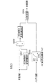
等価回路モデル演算部10は、電圧・電流変動値演算部11、RLS(Recursive Least Square:逐次最小二乗法)同定部12、OCV推定部13およびSOC変換部14を有する。
電圧・電流変動値演算部11は、入力された実電圧値、実電流値と、記憶部40に一時記憶している前回実電圧値、前回実電流値から、実電圧変動値および実電流変動値を算出する機能を有する。
RLS同定部12は、電圧・電流変動値演算部11から入力された実電圧変動値および実電流変動値と、温度センサ80から入力されたバッテリ温度を基に、逐次最小二乗法によってバッテリの内部抵抗値を推定する機能を有する。
OCV推定部13は、RLS同定部12から入力された内部抵抗値の推定値を基に、OCVを推定する機能を有する。
そして、SOC変換部14は、図示しないOCV−SOCマップを用いて、OCVから等価回路モデル方式によるSOCを推定する機能を有する。
なお、等価回路モデル演算部10は、公知の技術(例えば、特開2009−103471号公報参照)である。
The equivalent circuit
The voltage / current fluctuation
Based on the actual voltage fluctuation value and the actual current fluctuation value input from the voltage / current fluctuation
The
And the
The equivalent circuit
記憶部40には、後記して説明する安定電流値マップ41、安定電流変動値マップ42、安定電圧変動値マップ43、基準抵抗値マップ44が格納されている。なお、安定電流値マップ41、安定電流変動値マップ42、安定電圧変動値マップ43、基準抵抗値マップ44の代わりに、各マップ41〜44に相当する関数が格納されていてもよい。
なお、バッテリ容量算出装置1は、ECU(Electronic Control Unit)などに搭載されるものであり、等価回路モデル演算部10、タイミング条件判定部20、バッテリ容量演算部30および等価回路モデル演算部10における各部11〜14はROM(Read Only Memory)などに格納されたプログラムが、CPU(Central Processing Unit)によって実行されることによって具現化する。
The storage unit 40 stores a stable
The battery
次に、図2〜図5を参照して、第1のタイミングおよび第2のタイミングを検出するための条件Z1〜Z5を判定する処理を説明する。 Next, processing for determining the conditions Z1 to Z5 for detecting the first timing and the second timing will be described with reference to FIGS.
(条件Z1:推定電圧値と実電圧値の差分値が所定値以下)
図2(a)は、本実施形態に係る条件Z1を判定するためのブロック線図である。
条件Z1は、実電圧変動値と、等価回路モデルを使用して推定された電圧変動値の誤差が大きいときは、等価回路モデル方式のモデル化誤差が大きいため、バッテリ容量を算出するための第1のタイミングおよび第2のタイミングとはしないための条件である。
まず、タイミング条件判定部20は、電圧センサ60、電流センサ70から入力された実電圧値、実電流値から、記憶部40に一時記憶していた実電圧値、実電流値の前回値を減算することによって、実電圧変動値、実電流変動値を算出する。そして、タイミング条件判定部20は、実電流変動値に等価回路モデル演算部10によって算出された内部抵抗値の推定値を乗算することによって(S101)、電圧変動値の推定値を算出する。
(Condition Z1: The difference value between the estimated voltage value and the actual voltage value is a predetermined value or less)
FIG. 2A is a block diagram for determining the condition Z1 according to the present embodiment.
The condition Z1 is that when the error between the actual voltage fluctuation value and the voltage fluctuation value estimated using the equivalent circuit model is large, the modeling error of the equivalent circuit model method is large, so that the first calculation for calculating the battery capacity is performed. This is a condition for avoiding the
First, the timing
次に、タイミング条件判定部20は、実電圧変動値から電圧変動値の推定値を減算することによって(S102)、電圧変動値の差分値を算出する。
そして、タイミング条件判定部20は、予め設定してある閾値(所定の誤差)と、ステップS102で算出した差分値とを比較し(S103)、比較結果を出力する。タイミング条件判定部20は、例えば、差分値が閾値以下であれば比較結果として「1」、差分値が閾値より大きければ「0」を出力する。
なお、閾値の値は、例えば1mVなどが考えられる。
Next, the timing
Then, the timing
Note that the threshold value may be 1 mV, for example.
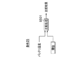
(条件Z2:電流センサ70から入力された実電流値が所定値以下、もしくは実電流値が所定範囲内)
図2(b)は、本実施形態に係る条件Z2を判定するためのブロック線図である。
条件Z2は、大電流が流れているときや、実電流値が小さいときは、等価回路モデル方式のモデル化誤差が大きいため、バッテリ容量を算出するための第1のタイミングおよび第2のタイミングとはしないための条件である。大電流が流れるときとは、車両加速時にバッテリからモータへの供給電力が大きいときや、車両減速時にモータからバッテリへの回生電力量が大きいときなどである。
まず、タイミング条件判定部20は、温度センサ80から入力されたバッテリ温度を基に、記憶部40に記憶されている安定電流値マップ41から、入力されたバッテリ温度における安定電流値を算出する(S201)。図2(b)に示すように安定電流値マップ41は、バッテリ温度(T[℃])と、安定電流値(I[A])とが対応付けられているマップである。
そして、タイミング条件判定部20は、実電流値の絶対値を算出すると(S202)、この絶対値と、ステップS201で算出した安定電流値(所定の電流値)を比較し(S203)、比較結果を出力する。ステップS202で絶対値を算出したのは、充電方向と放電方向で電流の符号が変わることを考慮するためである。タイミング条件判定部20は、例えば、絶対値が安定電流値以下であれば、比較結果として「1」を出力し、絶対値が安定電流値より大きければ「0」を出力する。
(Condition Z2: The actual current value input from the current sensor 70 is equal to or less than a predetermined value, or the actual current value is within a predetermined range)
FIG. 2B is a block diagram for determining the condition Z2 according to the present embodiment.
The condition Z2 is that when a large current flows or when the actual current value is small, the modeling error of the equivalent circuit model method is large, so the first timing and the second timing for calculating the battery capacity are This is a condition for not. The time when a large current flows is when the power supplied from the battery to the motor is large during vehicle acceleration, or when the amount of regenerative power from the motor to the battery is large during vehicle deceleration.
First, the timing
Then, the timing
なお、図2(b)では、ステップS202の絶対値が安定電流値以下であれば「1」を出力するとしたが、タイミング条件判定部20は以下の手順で実電流値の絶対値が所定範囲内にあることを判定してもよい。すなわち、バッテリ容量算出装置1は最高安定電流値マップ、最低安定電流値マップを記憶部40に格納しており、タイミング条件判定部20はバッテリ温度を基に、最高安定電流値マップ、最低安定電流値マップから最高安定電流値(所定の上限電流値)および最低安定電流値(所定の下限電流値)を算出する。そして、タイミング条件判定部20は、実電流値の絶対値が最高安定電流値および最低安定電流値の範囲内であれば「1」を出力し、絶対値が最高安定電流値および最低安定電流値の範囲外であれば「0」を出力する。
さらに、タイミング条件判定部20は、絶対値が30[A]以下であれば「1」を出力したり、絶対値が3[A]以上30[A]以下であれば「1」を出力したりするなど、マップを用いずに定数値で判定を行ってもよい。
In FIG. 2B, “1” is output if the absolute value in step S202 is equal to or less than the stable current value. However, the timing
Furthermore, the timing
(条件Z3:所定期間内における実電流変動値が所定値以下)
図3は、本実施形態に係る条件Z3を判定するためのブロック線図である。
条件Z3は、実電流値の変動が大きいときは、等価回路モデル方式のモデル化誤差が大きいため、バッテリ容量を算出するための第1のタイミングおよび第2のタイミングとはしないための条件である。
まず、タイミング条件判定部20は、予め設定されており、記憶部40に一時記憶されている所定時間ΔT1前の実電流値を取得し(S301)、実電流値の現在値から、所定時間前の実電流値を減算して(S302)、所定期間内実電流変動値ΔI0を算出する。なお、所定時間ΔT1は、例えば1秒間が設定される。
一方、タイミング条件判定部20は、温度センサ80から入力されたバッテリ温度と、記憶部40に格納されている安定電流変動値マップ42から、このバッテリ温度における安定電流変動値を算出する(S303)。図3に示すように、安定電流変動値マップ42は、バッテリ温度(T[℃])と、安定電流変動値(ΔI[A])とが対応付けられているマップである。
(Condition Z3: Actual current fluctuation value within a predetermined period is not more than a predetermined value)
FIG. 3 is a block diagram for determining the condition Z3 according to the present embodiment.
The condition Z3 is a condition for avoiding the first timing and the second timing for calculating the battery capacity because the modeling error of the equivalent circuit model method is large when the fluctuation of the actual current value is large. .
First, the timing
On the other hand, the timing
そして、タイミング条件判定部20は、所定期間内実電流変動値(ΔI0)と、安定電流変動値(ΔI:所定の電流変動値)とを比較し(S304)、比較結果を出力する。タイミング条件判定部20は、例えば、実電流変動値が安定電流変動値以下であれば、比較結果として「1」を出力し、実電流変動値が安定電流変動値より大きければ、比較結果として「0」を出力する。
なお、実電流変動値が10[A]以下であれば、タイミング条件判定部20は比較結果として「1」を出力するなど、マップを用いずに定数で比較を行ってもよい。
Then, the timing
Note that if the actual current fluctuation value is 10 [A] or less, the timing
(条件Z4:所定期間内における実電圧変動値が所定値以下)
図4は、本実施形態に係る条件Z4を判定するためのブロック線図である。
条件Z4は、実電圧値の変動が大きいときは、等価回路モデル方式のモデル化誤差が大きいため、バッテリ容量を算出するための第1のタイミングおよび第2のタイミングとはしないための条件である。
まず、タイミング条件判定部20は、予め設定されており、記憶部40に一時記憶している所定時間ΔT2前の実電圧値を取得し(S401)、実電圧値の現在値から所定時間前の実電圧値を減算して(S402)、所定期間内実電圧変動値ΔV0を算出する。なお、所定時間ΔT2は、例えば1秒間が設定される。
一方、タイミング条件判定部20は、温度センサ80から入力されたバッテリ温度と、記憶部40に格納されている安定電圧変動値マップ43から安定電圧値変動値を取得する(S403)。図4に示すように安定電圧変動値マップ43は、バッテリ温度(T[℃])と、安定電圧変動値(ΔV[V])とが対応付けられているマップである。
(Condition Z4: Actual voltage fluctuation value within a predetermined period is not more than a predetermined value)
FIG. 4 is a block diagram for determining the condition Z4 according to the present embodiment.
The condition Z4 is a condition for avoiding the first timing and the second timing for calculating the battery capacity because the modeling error of the equivalent circuit model method is large when the fluctuation of the actual voltage value is large. .
First, the timing
On the other hand, the timing
また、タイミング条件判定部20は、入力されたバッテリ温度と、記憶部40に記憶されている基準抵抗値マップ44から基準抵抗値R0を算出する(S404)。基準抵抗値とは、例えば、新品のバッテリにおいて、該当するバッテリ温度下の内部抵抗値などである。図4に示すように、基準抵抗値マップ44はバッテリ温度(T[℃])と、基準抵抗値(R0[mΩ])とが対応付けられているマップである。
そして、タイミング条件判定部20は等価回路モデルで算出した推定内部抵抗値Rを、ステップS404で算出したR0で除算し(S405)、算出したR/R0をステップS403で算出した安定電圧変動値に乗算する(S406)。これは、バッテリの劣化に伴う内部抵抗値の影響を考慮するために行われる処理である。
Further, the timing
Then, the timing
最後に、タイミング条件判定部20はステップS402で算出した所定期間内実電圧変動値(ΔV0)と、ステップS406でR/R0を乗算された安定電圧変動値(所定の電圧変動値)とを比較し(S407)、比較結果を出力する。
タイミング条件判定部20は、例えば、実電圧変動値が安定電圧変動値以下であれば、比較結果として「1」を出力し、実電圧変動値が安定電圧変動値より大きければ「0」を出力する。
なお、実電圧変動値が0.1[V]以下であれば、タイミング条件判定部20は比較結果として「1」を出力するなど、マップを用いずに定数を用いてもよい。
Finally, the timing
For example, the timing
If the actual voltage fluctuation value is 0.1 [V] or less, the timing
(条件Z5:バッテリ温度が所定値以上)
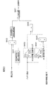
図5は、本実施形態に係る条件Z5を判定するためのブロック線図である。
条件Z5は、極低温条件下ではバッテリの内部抵抗値が大きくなるため、このような極低温条件下では等価回路モデル方式のモデル化誤差が大きくなるのでバッテリ容量を算出するための第1のタイミングおよび第2のタイミングとはしないための条件である。
タイミング条件判定部20は、温度センサ80から入力されたバッテリ温度と、予め設定してある閾値(所定の電池温度)とを比較し(S501)、比較結果を出力する。
タイミング条件判定部20は、例えば、バッテリ温度が閾値より大きければ「1」を出力し、バッテリ温度が閾値以下であれば「0」を出力する。
閾値としては、例えば「−30[℃]」などが考えられる。
(Condition Z5: Battery temperature is a predetermined value or more)
FIG. 5 is a block diagram for determining the condition Z5 according to the present embodiment.
In the condition Z5, since the internal resistance value of the battery becomes large under extremely low temperature conditions, the modeling error of the equivalent circuit model method becomes large under such extremely low temperature conditions, so the first timing for calculating the battery capacity This is a condition for avoiding the second timing.
The timing
For example, the timing
As the threshold value, for example, “−30 [° C.]” can be considered.
(等価回路モデル演算処理)
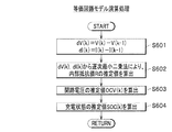
次に、図6〜図8を参照して、等価回路モデル演算処理、タイミング条件判定処理およびバッテリ容量演算処理の説明を行う。
図6は、等価回路モデル演算処理の流れを示すフローチャートである。図6に示す等価回路モデル演算処理は、前記したように公知の処理である。等価回路モデル演算処理は特開2009−103471号公報などに記載されている技術である。
まず、実電圧値の今回値をV(k)、実電流の今回値をI(k)、実電圧値の前回値をV(k−1)、実電流値の前回値をI(k−1)、実電流変動値をdV(k)、実電流変動値をdI(k)とすると、電圧・電流変動値演算部11は、以下の式(1)、式(2)を演算することにより実電圧変動値(dV(k))と、実電流変動値((dI(k))とを算出する(S601)。
(Equivalent circuit model calculation processing)
Next, an equivalent circuit model calculation process, a timing condition determination process, and a battery capacity calculation process will be described with reference to FIGS.
FIG. 6 is a flowchart showing the flow of the equivalent circuit model calculation process. The equivalent circuit model calculation process shown in FIG. 6 is a known process as described above. The equivalent circuit model calculation processing is a technique described in Japanese Patent Application Laid-Open No. 2009-103471.
First, the current value of the actual voltage value is V (k), the current value of the actual current is I (k), the previous value of the actual voltage value is V (k−1), and the previous value of the actual current value is I (k− 1) When the actual current fluctuation value is dV (k) and the actual current fluctuation value is dI (k), the voltage / current fluctuation
dV(k)=V(k)−V(k−1) ・・・(1)
dI(k)=I(k)−I(k−1) ・・・(2)
dV (k) = V (k) −V (k−1) (1)
dI (k) = I (k) -I (k-1) (2)
次に、RLS同定部12が、ステップS601で算出した実電圧変動値(dV(k))および実電流変動値(dI(k))から、逐次最小二乗法により内部抵抗値Rの推定値を算出する(S602)。
そして、OCV推定部13が、推定した内部抵抗値を基に、バッテリの開路電圧値の推定値OCV(k)を算出する(S603)。
そして、SOC変換部14が、ステップS603で算出された開路電圧値の推定値OCV(k)を基に、等価回路モデルによる充電状態の推定値SOC(k)を算出する(S604)。
ステップS604で算出された充電状態の推定値SOC(k)はバッテリ容量演算部30へ出力され、等価回路モデル演算部10はステップS601へリターンする。
Next, the
Then, the
Then, the
The estimated state of charge SOC (k) calculated in step S604 is output to the battery
(タイミング条件判定処理)
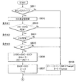
図7は、本実施形態に係るタイミング条件判定処理の流れを示すフローチャートである。
まず、タイミング条件判定部20は、等価回路モデル演算部10から実電圧変動値(dV(k))と、実電流変動値(dI(k))と、バッテリの内部抵抗の推定値(R)とを取得すると、図2(a)で説明した処理を行うことによって、条件Z1が成立しているか否か、すなわち式(3)の不等式が成立しているか否かを判定する(S701)。なお、式(4)における閾値は所定の誤差である。
(Timing condition judgment processing)
FIG. 7 is a flowchart showing a flow of timing condition determination processing according to the present embodiment.
First, the timing
|dV(k)−dI(k)×R|≦閾値 ・・・(3) | DV (k) −dI (k) × R | ≦ threshold value (3)
ステップS701の結果、式(3)の不等式が成立していない場合(S701→No:条件Z1が不成立:図2(a)の比較結果が「0」に相当)、タイミング条件判定部20はタイミングフラグを「0」として(S707)、バッテリ容量演算部30へ出力し、ステップS701へリターンする。
As a result of step S701, when the inequality of the expression (3) is not satisfied (S701 → No: the condition Z1 is not satisfied: the comparison result of FIG. 2A corresponds to “0”), the timing
ステップS701の結果、式(3)の不等式が成立している場合(S701→Yes:条件Z1が成立:図2(a)の比較結果が「1」に相当)、タイミング条件判定部20は、図2(b)で説明した処理を行うことによって、条件Z2が実電流値の絶対値(|I|)が所定下限値(図2(b)における最低安定電流値:所定の下限電流値)以上、所定上限値(図2(b)における最高安定電流値:所定の上限電流値)以下であるか否かを判定する(S702)。
なお、ステップS702の処理は、前記した図2(b)で実電流値の絶対値が所定範囲内に入っているか否かを判定したものであり、ステップS702においてタイミング条件判定部20は実電流値の絶対値が所定値(所定の電流値)以下であるか否かを判定してもよい。
ステップS702の結果、実電流値の絶対値が所定上限値より大きいか、または所定下限値未満の場合(S702→No:条件Z2が不成立:図2(b)の比較結果が「0」に相当)、タイミング条件判定部20はタイミングフラグを「0」として(S707)、バッテリ容量演算部30へ出力し、ステップS701へリターンする。
As a result of Step S701, when the inequality of Expression (3) is satisfied (S701 → Yes: Condition Z1 is satisfied: the comparison result of FIG. 2A corresponds to “1”), the timing
Note that the processing in step S702 is to determine whether or not the absolute value of the actual current value is within a predetermined range in FIG. 2B. In step S702, the timing
As a result of step S702, when the absolute value of the actual current value is larger than the predetermined upper limit value or smaller than the predetermined lower limit value (S702 → No: Condition Z2 is not satisfied: the comparison result in FIG. 2B corresponds to “0”) ), The timing
ステップS702の結果、実電流値の絶対値が所定上限値以下、所定下限値以上である場合(S702→Yes:条件Z2が成立:図2(b)の比較結果が「1」に相当)、タイミング条件判定部20は、図3で説明した処理を行うことによって、条件Z3が成立するか否か、すなわち所定期間内実電流変動値(ΔI0)が、所定値(図3における安定電流変動値ΔI:所定の電流変動値)以下であるか否かを判定する(S703)。
ステップS703の結果、所定期間内実電流変動値(ΔI0)が所定値より大きい場合(S703→No:条件Z3が不成立:図3の比較結果が「0」に相当)、タイミング条件判定部20はタイミングフラグを「0」として(S707)、バッテリ容量演算部30へ出力し、ステップS701へリターンする。
As a result of step S702, when the absolute value of the actual current value is not more than the predetermined upper limit value and not less than the predetermined lower limit value (S702 → Yes: Condition Z2 is satisfied: the comparison result in FIG. 2B corresponds to “1”). The timing
As a result of step S703, when the actual current fluctuation value (ΔI0) within the predetermined period is larger than the predetermined value (S703 → No: Condition Z3 is not satisfied: the comparison result in FIG. 3 is equivalent to “0”), the timing
ステップS703の結果、所定期間内実電流変動値(ΔI0)が所定値以下である場合(S703→Yes:条件Z3が成立:図3の比較結果が「1」に相当)、タイミング条件判定部20は、図4で説明した処理を行うことによって、条件Z4が成立するか否か、すなわち所定期間内実電圧変動値(ΔV0)が、所定値(図4における安定電圧変動値ΔV:所定の電圧変動値)以下であるか否かを判定する(S704)。
ステップS704の結果、所定期間内実電圧変動値(ΔV0)が所定値より大きい場合(S704→No:条件Z4が不成立:図4の比較結果が「0」に相当)、タイミング条件判定部20はタイミングフラグを「0」として(S707)、バッテリ容量演算部30へ出力し、ステップS701へリターンする。
As a result of step S703, when the actual current fluctuation value (ΔI0) within the predetermined period is equal to or less than the predetermined value (S703 → Yes: Condition Z3 is satisfied: the comparison result in FIG. 3 corresponds to “1”), the timing
As a result of step S704, when the actual voltage fluctuation value (ΔV0) within the predetermined period is larger than the predetermined value (S704 → No: Condition Z4 is not satisfied: the comparison result in FIG. 4 is equivalent to “0”), the timing
ステップS704の結果、所定期間内実電圧変動値(ΔV0)が所定値以下である場合(S704→Yes:条件Z4が成立:図4の比較結果が「1」に相当)、タイミング条件判定部20は、図5で説明した処理を行うことによって、条件Z5が成立するか否か、すなわちバッテリ温度Tが閾値以上であるか否かを判定する(S705)。
ステップS705の結果、バッテリ温度Tが閾値(所定の電池温度)未満である場合(S705→No:条件Z5が不成立:図5の比較結果が「0」に相当)、タイミング条件判定部20はタイミングフラグを「0」として(S707)、バッテリ容量演算部30へ出力し、ステップS701へリターンする。
As a result of step S704, when the actual voltage fluctuation value (ΔV0) within the predetermined period is equal to or smaller than the predetermined value (S704 → Yes: Condition Z4 is satisfied: the comparison result in FIG. 4 is equivalent to “1”), the timing
When the battery temperature T is lower than the threshold value (predetermined battery temperature) as a result of step S705 (S705 → No: Condition Z5 is not established: the comparison result in FIG. 5 is equivalent to “0”), the timing
ステップS705の結果、バッテリ温度Tは閾値以上である場合(S705→Yes:条件Z5が成立:図5の比較結果が「1」に相当)、タイミング条件判定部20はタイミングフラグを「1」として(S706)、バッテリ容量演算部30へ出力し、ステップS701へリターンする。
As a result of step S705, when the battery temperature T is equal to or higher than the threshold (S705 → Yes: Condition Z5 is satisfied: the comparison result in FIG. 5 corresponds to “1”), the timing
なお、本実施形態では、条件Z1〜Z5のすべてが成立した場合にタイミングフラグを「1」としたが、少なくとも条件Z1が成立していればタイミングフラグを「1」としてもよい。 In this embodiment, the timing flag is set to “1” when all of the conditions Z1 to Z5 are satisfied. However, the timing flag may be set to “1” when at least the condition Z1 is satisfied.
(バッテリ容量演算処理)
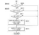
図8および図9は、本実施形態に係るバッテリ容量演算処理の流れを示すフローチャートである。
まず、バッテリ容量演算部30は、タイミング条件判定部20から取得したタイミングフラグが「1」であるか否かを判定する(図8のS801)ことによって、条件Z1〜Z5が成立したか否かを判定する。なお、条件Z1〜Z5のすべて成立したときのみ「Yes」と判定してもよいし、少なくとも条件Z1が成立したときに「Yes」と判定してもよい。ここで、前回SOC検出条件が成立したタイミングが第1の検出タイミングとなり、今回SOC検出条件が成立したタイミングが第2の検出タイミングとなる。
ステップS801の結果、タイミングフラグが「1」である場合(S801→Yes)、バッテリ容量演算部30は等価回路モデル演算部10から等価回路モデル方式によるSOC推定値を取得する(S802)。
そして、バッテリ容量演算部30は、ステップS802で取得したSOC推定値(SOC)から、記憶部に一時記憶しているSOC推定値の前回値(SOCP)を減算した値の絶対値(|SOC−SOCP|)が所定値以上であるか否かを判定する(S803:条件W1)。ステップS803における所定値としては、5(%)などが考えられる。
(Battery capacity calculation processing)
8 and 9 are flowcharts showing the flow of the battery capacity calculation process according to the present embodiment.
First, the battery
As a result of step S801, when the timing flag is “1” (S801 → Yes), the battery
Then, the battery
ステップS803の結果、所定値以上である場合(S803→Yes:条件W1が成立)、バッテリ容量演算部30は、後記するステップS808において実電流値を積算した値の絶対値(|ΣI|)が所定値以上であるか否かを判定する(S804:条件W2)。ステップS804における所定値としては0.1(Ah)などが考えられる。
ステップS804の結果、所定値以上である場合(S804→Yes:条件W2が成立)、バッテリ容量演算部30は前回SOC検出条件が成立してからの経過時間Tが、所定時間T1以上であるか否かを判定する(S805:条件W3の下限条件)。なお、T1としては10(sec)などが考えられる。
If the result of step S803 is equal to or greater than the predetermined value (S803 → Yes: condition W1 is satisfied), the
If the result of step S804 is equal to or greater than the predetermined value (S804 → Yes: condition W2 is satisfied), battery
ステップS805の結果、経過時間Tが、所定時間T1以上である場合(S805→Yes:条件W3の加減が成立)、バッテリ容量演算部30はSOC推定値の今回値(SOC)から、SOC推定値の前回値(SOCP)を減算した値をΔSOC(電池の残容量の変化率)とし(ΔSOC=SOC−SOCP)、実電流値を積算した値の絶対値をΔAh(電池の容量変化値)とし(ΔAh=ΣI)、カウンタCNTを1インクリメントする(CNT=CNT+1)(S806)。
その後、バッテリ容量演算部30はSOCの前回値(SOCP)を今回値(SOC)で更新し(SOCP=SOC)、実電流値の積算値を「0」に更新し(ΣI=0)、経過時間Tを「0」に更新し(T=0)(S807)、ステップS809へ処理を進める。
As a result of step S805, when the elapsed time T is equal to or longer than the predetermined time T1 (S805 → Yes: the condition W3 is adjusted), the battery
Thereafter, the battery
一方、ステップS801,S803,S804,S805のいずれかで「No」が判定された場合(つまり、条件W1〜W3のいずれかが不成立の場合)、バッテリ容量演算部30は、電流センサから取得した実電流値Iを用いて、電流積算値ΣIを以下の式(4)に従って更新し、経過時間Tに演算周期Tsampleを加えて経過時間Tを更新し(T=T+Tsample)(S808)、ステップS809へ処理を進める。
On the other hand, when “No” is determined in any of steps S801, S803, S804, and S805 (that is, when any of the conditions W1 to W3 is not established), the battery
ΣI=ΣI+I/(3600×Tsample) ・・・(4) ΣI = ΣI + I / (3600 × Tsample) (4)
ステップS807およびステップS808の後、バッテリ容量演算部30は、前回SOC検出条件が成立してからの経過時間Tが、所定時間T2以下であるか否かを判定する(図9のS809:条件W3の上限条件)。なお、T2としては120(sec)などが考えられる。
ステップS809の結果、経過時間Tが、所定時間T2以下である場合(S809→Yes:条件W3の上限条件が成立)、バッテリ容量演算部30はΔSOC×ΔAhが正の値であるか否かを判定し(S810)、ΔSOCとΔAhの正負が同符号であるか否かを判定する(条件W4)。
ステップS810でΔSOC×ΔAhが正の値である場合(S810→Yes:条件W4が成立)、バッテリ容量演算部30は、カウンタCNTがバッテリ容量演算条件成立回数ESTNより大きな値であるか否かを判定する(S811)。ステップS811の処理は、ステップS806を経過したときのみ、つまり条件W1,W2と、条件W3の下限条件が成立したときのみステップS812でバッテリ容量を算出するためである。
After step S807 and step S808, the battery
As a result of step S809, when the elapsed time T is equal to or shorter than the predetermined time T2 (S809 → Yes: the upper limit condition of the condition W3 is satisfied), the battery
When ΔSOC × ΔAh is a positive value in step S810 (S810 → Yes: Condition W4 is satisfied), the battery
ステップS811でカウンタCNTがバッテリ容量演算条件成立回数ESTNより大きな値である場合(S811→Yes)、バッテリ容量演算部30は、バッテリ容量の前回値CAPAや、予め設定してある重み係数W(0≦W≦1)などを用いて、式(5)よりバッテリ容量を更新し、さらにバッテリ容量演算条件成立回数ESTNをカウンタCNTで更新する(S812)。バッテリ容量演算部30が、式(5)を演算することにより、センサのエラーなどが原因による算出バッテリ容量の急激な変化を防止することができる。
In step S811, when the counter CNT is larger than the number of times the battery capacity calculation condition is established ESTN (S811 → Yes), the battery
CAPA=W×CAPA+(1−W)×(ΔAh/ΔSOC) ・・・(5) CAPA = W × CAPA + (1−W) × (ΔAh / ΔSOC) (5)
なお、ステップS812において、過去n回のバッテリ容量を用いて移動平均のようにバッテリ容量の今回値を算出してもよい。
また、ステップS812において、重み係数を使用せずに以下の式(6)からバッテリ容量CAPAを算出してもよい。
In step S812, the current value of the battery capacity may be calculated like a moving average using the battery capacity of the past n times.
In step S812, the battery capacity CAPA may be calculated from the following equation (6) without using a weighting factor.
CAPA=ΔAh/ΔSOC ・・・(6) CAPA = ΔAh / ΔSOC (6)
そして、バッテリ容量演算部30は、ステップS812で更新したバッテリ容量CAPAと、前回の最終バッテリ容量CAPAFと、予め設定してあるフィルタ係数F(0≦F≦1)を用いて、式(7)より最終バッテリ容量CAPAFを更新し(S813)、ステップS801へリターンする。ステップS813は、最終バッテリ容量が急激に変化することを防止するために行うフィルタ演算である。
Then, the battery
CAPAF=F×CAPA+(1−F)×CAPAF ・・・(7) CAPAF = F × CAPA + (1−F) × CAPAF (7)
なお、ステップS809、ステップS810で「No」(条件W3の上限条件またはW4が不成立)またはステップS811で「No」が判定されたとき、バッテリ容量演算部30はステップS812をスキップしてステップS813の処理を行う。つまり、バッテリ容量CAPAの値は更新されずにステップS813の処理が行われる。
When “No” is determined in step S809 and step S810 (the upper limit condition of condition W3 or W4 is not established) or “No” is determined in step S811, battery
なお、条件W1〜W4はすべて成立する必要はなく、少なくとも条件W3の上限条件および条件W4が成立していればよい。つまり、図8において少なくともステップS801,S806,S807,S808,S810,S812が実行されればよい。 Note that all of the conditions W1 to W4 do not need to be satisfied, and it is sufficient that at least the upper limit condition and the condition W4 of the condition W3 are satisfied. In other words, at least steps S801, S806, S807, S808, S810, and S812 need only be executed in FIG.
(まとめ)
本実施形態によれば、電流センサ70の誤差が蓄積される電流積算方式を用いずに、等価回路モデル方式によるSOC推定値を用いてバッテリ容量の算出を行うことができる。このとき、等価回路モデル方式で大きな誤差が生じる条件Z1〜Z5を避けたタイミングを、バッテリ容量算出のための第1のタイミングおよび第2のタイミングとすることができるため、高精度のバッテリ容量の算出が可能となる。
従って、電池の特性変化に追従できる等価回路モデルを使用した精度の高いバッテリ容量の算出が可能となる。
(Summary)
According to the present embodiment, the battery capacity can be calculated using the estimated SOC value by the equivalent circuit model method without using the current integration method in which the error of the current sensor 70 is accumulated. At this time, the timings avoiding the conditions Z1 to Z5 that cause a large error in the equivalent circuit model method can be set as the first timing and the second timing for calculating the battery capacity. Calculation is possible.
Therefore, it is possible to calculate the battery capacity with high accuracy using an equivalent circuit model that can follow changes in battery characteristics.
1 バッテリ容量算出装置(電池容量検出装置)
10 等価回路モデル演算部
11 電圧・電流変動値演算部
12 RLS同定部
13 OCV推定部
14 SOC変換部
20 タイミング条件判定部
30 バッテリ容量演算部
40 記憶部
41 安定電流値マップ
42 安定電流変動値マップ
43 安定電圧変動値マップ
44 基準抵抗値マップ
60 電圧センサ
70 電流センサ
80 温度センサ
1 Battery capacity calculation device (battery capacity detection device)
DESCRIPTION OF
Claims (4)
前記第1の検出タイミングおよび前記第2の検出タイミングは、
等価回路モデルによる電圧推定値と、電圧センサから取得される実電圧値との誤差が所定の誤差以下であり、
電流センサから取得される実電流値が所定の電流値以下であり、
所定期間内の実電流変動値が所定の電流変動値以下であり、
所定期間内の実電圧変動値が所定の電圧変動値以下であり、
温度センサから取得される電池温度が所定の電池温度以上である
ことを特徴とする電池容量検出方法。
CAPA=ΔAh/ΔSOC ・・・(1)
ただし、CAPAは前記電池の満充電容量であり、ΔAhは前記第1の検出タイミングと、前記第2の検出タイミングとの間における前記電池の容量変化値であり、ΔSOCは第1の検出タイミングと、第2の検出タイミングとの間における等価回路モデル方式によって算出された電池の残容量の変化率である。 The full charge capacity of the battery according to the equation (1) from the battery capacity change value between the first detection timing and the second detection timing and the rate of change of the remaining battery capacity calculated by the equivalent circuit model method A battery capacity detection method by a battery capacity detection device for detecting
The first detection timing and the second detection timing are:
The error between the estimated voltage value based on the equivalent circuit model and the actual voltage value obtained from the voltage sensor is less than or equal to a predetermined error,
The actual current value obtained from the current sensor is less than or equal to a predetermined current value,
The actual current fluctuation value within the predetermined period is less than or equal to the predetermined current fluctuation value,
The actual voltage fluctuation value within the predetermined period is less than or equal to the predetermined voltage fluctuation value,
A battery capacity detection method, wherein the battery temperature acquired from the temperature sensor is equal to or higher than a predetermined battery temperature.
CAPA = ΔAh / ΔSOC (1)
However, CAPA is the full charge capacity of the battery, ΔAh is the capacity change value of the battery between the first detection timing and the second detection timing, and ΔSOC is the first detection timing. The change rate of the remaining capacity of the battery calculated by the equivalent circuit model method between the second detection timing and the second detection timing.
ことを特徴とする請求項1に記載の電池容量検出方法。 2. The battery capacity detection method according to claim 1, wherein the predetermined current value is equal to or lower than the predetermined current value and equal to or higher than a second predetermined current value lower than the predetermined current value.
CAPA(n)=W×CAPA(n−1)+(1−W)×(ΔAh/ΔSOC) ・・・(2)
ここで、CAPA(n)は前記満充電容量の今回値、CAPA(n−1)は前記満充電容量の前回値、Wは0≦W≦1の値をとる重み係数である。 The battery capacity detection method according to claim 1, wherein the full charge capacity is corrected by Equation (2).
CAPA (n) = W × CAPA (n−1) + (1−W) × (ΔAh / ΔSOC) (2)
Here, CAPA (n) is a current value of the full charge capacity, CAPA (n−1) is a previous value of the full charge capacity, and W is a weighting coefficient that takes a value of 0 ≦ W ≦ 1.
CAPAF(n)=F×CAPA(n)+(1−F)×CAPAF(n−1) ・・・(3)
ここで、CAPAF(n)は満充電容量フィルタ値の今回値、CAPAF(n−1)は満充電容量フィルタ値の前回値、Fは0≦F≦1の値をとるフィルタ係数である。 The battery capacity detection method according to claim 3, wherein the full charge capacity calculated by the equation (2) is corrected by the equation (3).
CAPAF (n) = F * CAPA (n) + (1-F) * CAPAF (n-1) (3)
Here, CAPAF (n) is the current value of the full charge capacity filter value, CAPAF (n−1) is the previous value of the full charge capacity filter value, and F is a filter coefficient that takes a value of 0 ≦ F ≦ 1.
Priority Applications (1)
| Application Number | Priority Date | Filing Date | Title |
|---|---|---|---|
| JP2009262017A JP2011106953A (en) | 2009-11-17 | 2009-11-17 | Method for detecting battery capacity |
Applications Claiming Priority (1)
| Application Number | Priority Date | Filing Date | Title |
|---|---|---|---|
| JP2009262017A JP2011106953A (en) | 2009-11-17 | 2009-11-17 | Method for detecting battery capacity |
Publications (1)
| Publication Number | Publication Date |
|---|---|
| JP2011106953A true JP2011106953A (en) | 2011-06-02 |
Family
ID=44230600
Family Applications (1)
| Application Number | Title | Priority Date | Filing Date |
|---|---|---|---|
| JP2009262017A Pending JP2011106953A (en) | 2009-11-17 | 2009-11-17 | Method for detecting battery capacity |
Country Status (1)
| Country | Link |
|---|---|
| JP (1) | JP2011106953A (en) |
Cited By (10)
| Publication number | Priority date | Publication date | Assignee | Title |
|---|---|---|---|---|
| WO2013144195A1 (en) * | 2012-03-28 | 2013-10-03 | Avl List Gmbh | Method for determining the capacity of an energy storage apparatus |
| CN103823185A (en) * | 2012-11-16 | 2014-05-28 | 丰田自动车株式会社 | Power storage system and method of calculating full charge capacity |
| WO2014196506A1 (en) * | 2013-06-03 | 2014-12-11 | 古河電気工業株式会社 | Charge control device and charge control method |
| CN105474026A (en) * | 2013-10-24 | 2016-04-06 | 罗伯特·博世有限公司 | The method used to determine the battery capacity of single-cell |
| JP2016513249A (en) * | 2013-07-04 | 2016-05-12 | エルジー・ケム・リミテッド | Battery SOC estimation method and system |
| JP2017223537A (en) * | 2016-06-15 | 2017-12-21 | 本田技研工業株式会社 | Battery state estimation device and battery state estimation method |
| JP2018048911A (en) * | 2016-09-21 | 2018-03-29 | 株式会社豊田自動織機 | Full charge capacity estimation device |
| WO2019012930A1 (en) * | 2017-07-12 | 2019-01-17 | 日立オートモティブシステムズ株式会社 | DEVICE FOR CONTROLLING RECHARGEABLE BATTERY |
| JP2019211289A (en) * | 2018-06-01 | 2019-12-12 | マツダ株式会社 | Battery capacity estimation device and battery capacity estimation method |
| JP2024006655A (en) * | 2022-07-04 | 2024-01-17 | トヨタ自動車株式会社 | Inspection method, program, computer device for power storage device |
-
2009
- 2009-11-17 JP JP2009262017A patent/JP2011106953A/en active Pending
Cited By (20)
| Publication number | Priority date | Publication date | Assignee | Title |
|---|---|---|---|---|
| WO2013144195A1 (en) * | 2012-03-28 | 2013-10-03 | Avl List Gmbh | Method for determining the capacity of an energy storage apparatus |
| CN103823185A (en) * | 2012-11-16 | 2014-05-28 | 丰田自动车株式会社 | Power storage system and method of calculating full charge capacity |
| JP2014102078A (en) * | 2012-11-16 | 2014-06-05 | Toyota Motor Corp | Power storage system and full charge capacity calculation method |
| US9272635B2 (en) | 2012-11-16 | 2016-03-01 | Toyota Jidosha Kabushiki Kaisha | Power storage system and method of calculating full charge capacity |
| CN103823185B (en) * | 2012-11-16 | 2016-12-07 | 丰田自动车株式会社 | Accumulating system and the method calculating full charge capacity |
| US9855854B2 (en) | 2013-06-03 | 2018-01-02 | Furukawa Electric Co., Ltd. | Charge control device and charge control method |
| WO2014196506A1 (en) * | 2013-06-03 | 2014-12-11 | 古河電気工業株式会社 | Charge control device and charge control method |
| JP2016513249A (en) * | 2013-07-04 | 2016-05-12 | エルジー・ケム・リミテッド | Battery SOC estimation method and system |
| US10073145B2 (en) | 2013-07-04 | 2018-09-11 | Lg Chem, Ltd. | Method and system for estimating state of charge of battery |
| CN105474026A (en) * | 2013-10-24 | 2016-04-06 | 罗伯特·博世有限公司 | The method used to determine the battery capacity of single-cell |
| JP2016540961A (en) * | 2013-10-24 | 2016-12-28 | ローベルト ボッシュ ゲゼルシャフト ミット ベシュレンクテル ハフツング | Method for determining the capacity of a battery cell |
| CN105474026B (en) * | 2013-10-24 | 2018-10-12 | 罗伯特·博世有限公司 | Method for the capacity for determining battery list pond |
| JP2017223537A (en) * | 2016-06-15 | 2017-12-21 | 本田技研工業株式会社 | Battery state estimation device and battery state estimation method |
| JP2018048911A (en) * | 2016-09-21 | 2018-03-29 | 株式会社豊田自動織機 | Full charge capacity estimation device |
| WO2019012930A1 (en) * | 2017-07-12 | 2019-01-17 | 日立オートモティブシステムズ株式会社 | DEVICE FOR CONTROLLING RECHARGEABLE BATTERY |
| JP2019020174A (en) * | 2017-07-12 | 2019-02-07 | 日立オートモティブシステムズ株式会社 | Secondary battery control device |
| JP2019211289A (en) * | 2018-06-01 | 2019-12-12 | マツダ株式会社 | Battery capacity estimation device and battery capacity estimation method |
| JP7183577B2 (en) | 2018-06-01 | 2022-12-06 | マツダ株式会社 | Battery capacity estimation device and battery capacity estimation method |
| JP2024006655A (en) * | 2022-07-04 | 2024-01-17 | トヨタ自動車株式会社 | Inspection method, program, computer device for power storage device |
| JP7647698B2 (en) | 2022-07-04 | 2025-03-18 | トヨタ自動車株式会社 | Method, program, and computer device for inspecting power storage device |
Similar Documents
| Publication | Publication Date | Title |
|---|---|---|
| JP2011106953A (en) | Method for detecting battery capacity | |
| JP2011106952A (en) | Method for estimating residual capacity of battery | |
| JP6240369B2 (en) | System and method for determining the state of charge of a battery | |
| JP7076193B2 (en) | Battery state estimation method and equipment based on error correction | |
| JP3873623B2 (en) | Battery charge state estimation means and battery deterioration state estimation method | |
| KR102177721B1 (en) | Apparatus and Method for estimating deterioration of battery pack | |
| JP6182025B2 (en) | Battery health estimation device and health estimation method | |
| JP5273794B2 (en) | Method and apparatus for estimating SOC value of secondary battery, and degradation determination method and apparatus | |
| JP6634854B2 (en) | Storage element management device, storage element management method, storage element module, storage element management program, and moving object | |
| EP3593155B1 (en) | A battery cell state of charge estimation method and a battery state monitoring system | |
| US10436850B2 (en) | Power storage apparatus and controlling method for the same | |
| KR102274383B1 (en) | Assessing the quantity of energy in a motor vehicle battery | |
| JPWO1999061929A1 (en) | Battery charge state estimation means and battery degradation state estimation method | |
| JP5929778B2 (en) | CHARGE RATE ESTIMATION DEVICE AND CHARGE RATE ESTIMATION METHOD | |
| CN109795368B (en) | Power supply control system and power supply control method | |
| JPH11346444A (en) | Method of estimating battery charge state | |
| JP5929880B2 (en) | Battery control device | |
| WO2019230033A1 (en) | Parameter estimation device, parameter estimation method, and computer program | |
| WO2016132813A1 (en) | Battery state estimation device | |
| JPWO2018179562A1 (en) | Battery condition estimation device | |
| WO2014191794A1 (en) | Cell monitoring apparatus, battery monitoring apparatus, integrated circuit and method of monitoring a rechargeable cell | |
| CN109959876A (en) | Battery status estimating device | |
| JP2014181924A (en) | Full charge capacity estimation method and device | |
| JP2013108919A (en) | Soc estimator | |
| CN110383094A (en) | Battery power status estimation method and battery status monitor system |