JP2011106903A - Sample pretreatment device for fluorescent x-ray analysis, and fluorescent x-ray analysis system including the same - Google Patents
Sample pretreatment device for fluorescent x-ray analysis, and fluorescent x-ray analysis system including the same Download PDFInfo
- Publication number
- JP2011106903A JP2011106903A JP2009260710A JP2009260710A JP2011106903A JP 2011106903 A JP2011106903 A JP 2011106903A JP 2009260710 A JP2009260710 A JP 2009260710A JP 2009260710 A JP2009260710 A JP 2009260710A JP 2011106903 A JP2011106903 A JP 2011106903A
- Authority
- JP
- Japan
- Prior art keywords
- solution
- substrate
- remaining amount
- fluorescent
- measured
- Prior art date
- Legal status (The legal status is an assumption and is not a legal conclusion. Google has not performed a legal analysis and makes no representation as to the accuracy of the status listed.)
- Pending
Links
- 238000002441 X-ray diffraction Methods 0.000 title claims description 24
- 239000000758 substrate Substances 0.000 claims abstract description 95
- 238000000354 decomposition reaction Methods 0.000 claims description 45
- 238000011084 recovery Methods 0.000 claims description 34
- 238000004458 analytical method Methods 0.000 claims description 19
- 239000012808 vapor phase Substances 0.000 claims description 14
- 238000004876 x-ray fluorescence Methods 0.000 claims description 13
- 238000001035 drying Methods 0.000 claims description 10
- 230000001678 irradiating effect Effects 0.000 claims description 4
- 238000005259 measurement Methods 0.000 claims description 4
- 238000004140 cleaning Methods 0.000 description 26
- 239000007788 liquid Substances 0.000 description 18
- 230000032258 transport Effects 0.000 description 16
- KRHYYFGTRYWZRS-UHFFFAOYSA-N Fluorane Chemical compound F KRHYYFGTRYWZRS-UHFFFAOYSA-N 0.000 description 14
- 239000007789 gas Substances 0.000 description 9
- 229910000040 hydrogen fluoride Inorganic materials 0.000 description 8
- IJGRMHOSHXDMSA-UHFFFAOYSA-N Atomic nitrogen Chemical compound N#N IJGRMHOSHXDMSA-UHFFFAOYSA-N 0.000 description 7
- 230000001186 cumulative effect Effects 0.000 description 7
- 239000012071 phase Substances 0.000 description 5
- 238000001514 detection method Methods 0.000 description 4
- 239000011261 inert gas Substances 0.000 description 4
- 229920001343 polytetrafluoroethylene Polymers 0.000 description 4
- 239000004810 polytetrafluoroethylene Substances 0.000 description 4
- 239000004065 semiconductor Substances 0.000 description 4
- 229910052757 nitrogen Inorganic materials 0.000 description 3
- 229910021642 ultra pure water Inorganic materials 0.000 description 3
- 239000012498 ultrapure water Substances 0.000 description 3
- 239000000356 contaminant Substances 0.000 description 2
- 238000004519 manufacturing process Methods 0.000 description 2
- 229920000915 polyvinyl chloride Polymers 0.000 description 2
- 239000004800 polyvinyl chloride Substances 0.000 description 2
- 238000004080 punching Methods 0.000 description 2
- XUIMIQQOPSSXEZ-UHFFFAOYSA-N Silicon Chemical compound [Si] XUIMIQQOPSSXEZ-UHFFFAOYSA-N 0.000 description 1
- 239000004809 Teflon Substances 0.000 description 1
- 229920006362 Teflon® Polymers 0.000 description 1
- 238000011109 contamination Methods 0.000 description 1
- 238000005260 corrosion Methods 0.000 description 1
- 230000007797 corrosion Effects 0.000 description 1
- 230000007423 decrease Effects 0.000 description 1
- 229910001873 dinitrogen Inorganic materials 0.000 description 1
- 238000007599 discharging Methods 0.000 description 1
- 230000000694 effects Effects 0.000 description 1
- 239000003344 environmental pollutant Substances 0.000 description 1
- 238000002474 experimental method Methods 0.000 description 1
- 238000009434 installation Methods 0.000 description 1
- 239000000155 melt Substances 0.000 description 1
- 231100000719 pollutant Toxicity 0.000 description 1
- -1 polytetrafluoroethylene Polymers 0.000 description 1
- 238000007781 pre-processing Methods 0.000 description 1
- 229910052710 silicon Inorganic materials 0.000 description 1
- 239000010703 silicon Substances 0.000 description 1
- 239000007921 spray Substances 0.000 description 1
- 238000005507 spraying Methods 0.000 description 1
- 239000000126 substance Substances 0.000 description 1
Images
Landscapes
- Analysing Materials By The Use Of Radiation (AREA)
Abstract
Description
本発明は、基板表面などに存在する被測定物を溶解後乾燥させて基板表面に保持する試料前処理装置およびそれを備えた蛍光X線分析システムに関するものである。 The present invention relates to a sample pretreatment apparatus that melts and drys an object to be measured existing on a substrate surface or the like and holds it on the substrate surface, and a fluorescent X-ray analysis system including the same.
従来、半導体基板に付着した微量の汚染物質などを蛍光X線分析するために、試料前処理装置から蛍光X線分析装置への基板の搬送を、ロボットハンドなどの搬送装置で行う蛍光X線分析システムがある(特許文献1参照)。このシステムにおける試料前処理装置は、基板表面などに存在する被測定物を反応性ガス(フッ化水素)により溶解後、その基板に溶液(フッ化水素酸)を滴下して保持具で保持しながら基板表面で移動させ、被測定物を回収後乾燥させて基板表面に保持するものである。 Conventionally, in order to perform X-ray fluorescence analysis of trace amounts of contaminants adhering to a semiconductor substrate, the substrate is transported from the sample pretreatment device to the fluorescence X-ray analysis device by a transfer device such as a robot hand. There is a system (see Patent Document 1). The sample pretreatment device in this system dissolves the object to be measured present on the surface of the substrate with a reactive gas (hydrogen fluoride), then drops the solution (hydrofluoric acid) on the substrate and holds it with a holder. However, it is moved on the substrate surface, and the object to be measured is recovered and dried and held on the substrate surface.
この試料前処理装置では、溶液を滴下するための圧力、溶液の流路を開閉する弁の開放時間および溶液の滴下量の相関関係をあらかじめ記憶するとともに、溶液を滴下するための圧力を検知し、その検知した圧力と前記相関関係とに基づいて、溶液を滴下するための弁の開放時間を決定する。これにより、溶液を滴下するための圧力が変動しても、所望の一定の滴下量が得られ、被測定物の回収が正しく行われるようにしている。 In this sample pretreatment device, the correlation between the pressure for dropping the solution, the opening time of the valve for opening and closing the solution flow path, and the amount of the solution dropped is stored in advance, and the pressure for dropping the solution is detected. Based on the detected pressure and the correlation, an opening time of the valve for dropping the solution is determined. Thereby, even if the pressure for dripping the solution fluctuates, a desired constant dripping amount can be obtained and the object to be measured can be collected correctly.
これに対し、近年、円板状の基板の側面に存在する被測定物まで回収して分析したいという要望があり、そのためには、滴下した溶液を基板表面の外周からわずかにはみ出させながら、しかも側面からこぼれ落ちないように、保持具で保持して移動させなければならず、例えば適切な滴下量100μリットルに対し、−10〜+0%というきわめて微量の誤差しか許されない。しかし、前記従来の試料前処理装置では、溶液の残量が減少してくると、このようなきびしい許容誤差を逸脱するおそれがあることが判明した。 On the other hand, in recent years, there has been a demand to collect and analyze even the object to be measured present on the side surface of the disk-shaped substrate. For this purpose, while dripping the dropped solution slightly out of the outer periphery of the substrate surface, In order not to spill from the side, it must be held and moved by a holding tool. For example, an extremely small amount of error of −10 to + 0% is allowed for an appropriate dropping amount of 100 μL. However, it has been found that the conventional sample pretreatment apparatus may deviate from such severe tolerances when the remaining amount of the solution decreases.
本発明は、このような問題に鑑みてなされたもので、基板表面などに存在する被測定物を反応性ガスにより溶解後、その基板に溶液を滴下して保持具で保持しながら基板表面で移動させ、被測定物を回収後乾燥させて基板表面に保持する試料前処理装置およびそれを備えた蛍光X線分析システムにおいて、溶液の残量の影響を受けずに所望の一定の滴下量が得られ、被測定物の回収が正しく行われるものを提供することを目的とする。 The present invention has been made in view of such a problem. After the object to be measured existing on the substrate surface or the like is dissolved with a reactive gas, the solution is dropped on the substrate and held on the substrate surface while being held by the holder. In a sample pretreatment apparatus and a fluorescent X-ray analysis system equipped with the sample pretreatment apparatus that moves and collects the object to be measured and then dries and holds it on the substrate surface, a desired constant drop amount can be obtained without being affected by the remaining amount of the solution. An object of the present invention is to provide a device that can be obtained and correctly collects an object to be measured.
前記目的を達成するために、本発明の第1構成の蛍光X線分析用試料前処理装置は、基板表面に存在する被測定物または基板表面に形成された膜の表面もしくは膜中に存在する被測定物を分解室内で反応性ガスにより溶解後乾燥させて基板表面に保持する気相分解装置と、表面に被測定物が存在する基板に溶液を滴下して保持具で保持しながら基板表面で移動させ、被測定物を回収後乾燥させて基板表面に保持する試料回収装置とを備え、さらに、以下の残量検知手段と、弁と、制御装置とを備える。残量検知手段は、前記溶液を収納した容器内における溶液の残量を検知する。弁は、前記容器内において所定の圧力で加圧された前記溶液の流路を開閉する。制御装置は、前記溶液の残量、前記弁の開放時間および溶液の滴下量の相関関係をあらかじめ記憶し、その記憶した相関関係および前記残量検知手段により検知された溶液の残量に基づいて、前記溶液を滴下するための前記弁の開放時間を決定する。 In order to achieve the above object, the sample pretreatment apparatus for fluorescent X-ray analysis according to the first configuration of the present invention exists on the surface of a measurement object existing on the substrate surface or a film formed on the substrate surface or in the film. A gas phase decomposition apparatus that dissolves the object to be measured with a reactive gas in the decomposition chamber and then dries it and holds it on the substrate surface, and the substrate surface while dropping the solution onto the substrate on which the object to be measured exists and holding it with a holder And a sample recovery device for recovering and drying the object to be measured and holding it on the substrate surface, and further comprising the following remaining amount detection means, a valve, and a control device. The remaining amount detecting means detects the remaining amount of the solution in the container storing the solution. The valve opens and closes the flow path of the solution pressurized at a predetermined pressure in the container. The control device stores in advance a correlation between the remaining amount of the solution, the opening time of the valve, and the dropping amount of the solution, and based on the stored correlation and the remaining amount of the solution detected by the remaining amount detecting means. , Determine the opening time of the valve for dripping the solution.
第1構成の蛍光X線分析用試料前処理装置によれば、溶液の残量、弁の開放時間および溶液の滴下量の相関関係をあらかじめ記憶するとともに、溶液の残量を検知し、その検知した溶液の残量と前記相関関係とに基づいて、溶液を滴下するための弁の開放時間を決定するので、溶液の残量の影響を受けずに、所望の一定の滴下量が得られ、被測定物の回収が正しく行われる。 According to the sample pretreatment apparatus for fluorescent X-ray analysis of the first configuration, the correlation between the remaining amount of the solution, the opening time of the valve, and the dropping amount of the solution is stored in advance, and the remaining amount of the solution is detected and detected. Since the opening time of the valve for dropping the solution is determined based on the remaining amount of the solution and the correlation, a desired constant dropping amount can be obtained without being affected by the remaining amount of the solution, The object to be measured is collected correctly.
本発明の第2構成の蛍光X線分析システムは、前記第1構成の蛍光X線分析用試料前処理装置と、前記気相分解装置または試料回収装置により基板表面に保持された被測定物に1次X線を照射して発生する蛍光X線の強度を測定する蛍光X線分析装置とを備える。第2構成の蛍光X線分析システムによっても、第1構成の蛍光X線分析用試料前処理装置と同様の効果がある。 The fluorescent X-ray analysis system of the second configuration of the present invention is a sample pretreatment device for fluorescent X-ray analysis of the first configuration and an object to be measured held on the substrate surface by the vapor phase decomposition device or the sample recovery device. And a fluorescent X-ray analyzer that measures the intensity of fluorescent X-rays generated by irradiating primary X-rays. The X-ray fluorescence analysis system having the second configuration also has the same effects as the sample X-ray fluorescence analysis sample pretreatment apparatus having the first configuration.
以下、本発明の一実施形態である蛍光X線分析システムについて、構成から説明する。図5(a),(b)の一部を破断した平面図、正面図に示すように、この蛍光X線分析システムは、まず、気相分解装置20および試料回収装置30を有する試料前処理装置10と、試料台41に載置された基板1上の被測定物2にX線源42から1次X線43を照射して発生する蛍光X線44の強度を検出手段45で測定する蛍光X線分析装置40と、前記試料前処理装置10から蛍光X線分析装置40へ基板1を搬送する搬送装置50とを備える。
Hereinafter, a configuration of an X-ray fluorescence analysis system according to an embodiment of the present invention will be described. As shown in a plan view and a front view in which a part of FIGS. 5A and 5B is broken, this fluorescent X-ray analysis system is first a sample pretreatment having a gas
この実施形態では、試料に対し1次X線を微小な入射角で照射する全反射蛍光X線分析装置40を採用し、X線源42は、X線管、単色化のための分光素子などを有し、検出手段45には、SSDなどを用いる。蛍光X線分析装置40は、ロボットハンドなどの搬送手段46を有しており、導入室のカセット47と試料台41との間で、基板1を搬送する。
In this embodiment, a total reflection
前記搬送装置50は、レールの上で本体が前後に移動自在なロボットハンドであり、そのハンド部50aに基板1を載置して、基板1を、蛍光X線分析システムのカセット台5に載置されたカセット3(所定の投入位置)から試料前処理装置10の分解室21または回収室31へ、分解室21から回収室31へ、分解室21または回収室31から蛍光X線分析装置40の導入室のカセット47へ、導入室のカセット47からもとのカセット台5に載置されたカセット3へ、搬送する。カセット台5には、複数のカセット3を載置できる。
The
蛍光X線分析システムは、半導体製造装置などが置かれるクリーンルーム6とそこで製造された半導体基板1を分析する分析室7とを隔てる壁8を突き抜けるように設置され、カセット台5のみがクリーンルーム内にある。カセット台5に載置されたカセット3と搬送装置50との間には図示しないシャッターが設けられている。
The X-ray fluorescence analysis system is installed so as to penetrate through a
蛍光X線分析システムは、前記試料前処理装置10、蛍光X線分析装置40、搬送装置50、カセット台5に載置されたカセット3と搬送装置50との間のシャッターなどを共通の環境(ソフトウエア)で制御するコンピュータなどの制御装置60を、例えば蛍光X線分析装置40内に配置して備える。各装置は、共通の基台上で、全体として一つの筐体に一体的に設けられている。
The X-ray fluorescence analysis system uses a common environment (such as a shutter between the cassette 3 placed on the
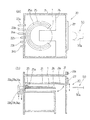
ここで、試料前処理装置10のうちの気相分解装置20の構成について説明する。図4(a),(b)に平面図、正面図に示す気相分解装置20は、基板1表面に存在する被測定物または基板表面に形成された膜の表面もしくは膜中に存在する被測定物を分解室21内で反応性ガスにより溶解後乾燥させて基板1表面に保持する。より具体的には、この気相分解装置20の分解室21は、例えばPTFE(ポリ四フッ化エチレン、テフロン(登録商標))製の箱であり、ロボットハンドなどの搬送装置50のハンド部50aに対向する側に、開閉自在の内側シャッター21aを有している。さらに、その内側シャッター21aから、上方の回収室31からの空気が流れ落ちる空間を隔てて、気相分解装置20の外壁に開閉自在の外側シャッター27が設けられている。分解室21内には、配管22aから反応性ガスとしてフッ化水素が導入され、例えばシリコンウエハである基板1表面に形成された酸化膜を溶解するとともに、膜の表面または膜中に存在する汚染物質などの被測定物を溶解し、配管22bから排出される。基板1表面に膜が形成されていない場合には、基板1表面に存在する被測定物が溶解される。
Here, the configuration of the vapor
気相分解装置20は、分解室21内に洗浄液として超純水を流して洗浄する分解室洗浄手段23、すなわち、洗浄液導入配管23aおよび排出配管23bを有している。また、分解室21内に不活性ガスとして清浄な窒素を流して、フッ化水素を追い出すとともに、基板1に生じた液滴を乾燥させる液滴乾燥手段24、すなわち、窒素導入配管24aおよび排出配管24bを有している。なお、液滴乾燥手段では、不活性ガスを流す代わりに、または不活性ガスを流すことに加えて、分解室内を減圧(真空排気)して、基板に生じた液滴を乾燥させてもよい。この場合、真空排気と不活性ガスの導入を繰り返し行ってもよい。
The vapor
また、基板1が分解室21内の所定の位置に載置されるように、内周に下向き狭小のテーパ25aが付いた基板台25を有している。すなわち、基板台25は、搬送装置のハンド部50aに干渉しないように一部を切り欠いた輪状で、内周に下向き円錐側面の一部をなすテーパ面25aが形成され、仕切り板26を介して分解室21内に固定されている。
In addition, a
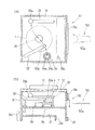
次に、試料回収装置30の構成について説明する。図2(a),(b)に平面図、正面図を示す試料回収装置30は、分解室21の上に配置された回収室31内で、表面に被測定物が存在する基板1に溶液4を滴下して保持具32aで保持しながら基板1表面で移動させ、被測定物を回収後乾燥させて基板1表面に保持する。より具体的には、この試料回収装置30の回収室31は、上部にファン11およびフィルター12が設けられた例えばPVC(ポリ塩化ビニル)製の箱であり、分解室21の上に配置され、搬送装置のハンド部50aに対向する側に、開閉自在のシャッター31aを有している。そのシャッター31a近傍(図2(a)中1点鎖線で囲む範囲)において回収室31の底板には多数のパンチング孔31bがあけられており、ファン11およびフィルター12を介して回収室31に流入した清浄な空気が、分解室21の内側シャッター21aの外側へ流れ落ちるようになっている。試料回収装置30は、以下の回収液移動手段32、回収液乾燥手段33、保持具洗浄手段34および回転台35を有している。
Next, the configuration of the
回収液移動手段32は、その先端部下側にある保持具32aを、回転台35に載置された基板1の上方において基板1の外側と中心間で円弧状に移動させるアームであり、保持具32aを上下方向にも移動させることができる。保持具32aは例えばPTFE製のノズルであり、分解室21のさらに下方の後述する容器から、PTFE製のチューブ84などを経由して溶液(フッ化水素酸)4が供給される。回転台35は、載置された基板1を水平面内で回転させる。すなわち、試料回収装置30は、保持具32aから基板1の外周近傍に滴下した所定量例えば100μリットルの溶液4を、基板1を回転させながら、保持具32aと基板1で挟むようにして保持しつつ基板1上で中心まで移動させて、基板1表面に存在する被測定物を回収する。
The recovery liquid moving means 32 is an arm that moves the
回収液乾燥手段33は、その先端部に下向きに設けられたランプ33aを、基板1の上方において基板1の外側と中心間で円弧状に移動させるアームである。すなわち、試料回収装置30は、基板1の中心上方にランプ33aを移動させ、被測定物を回収した溶液4を加熱して被測定物を乾燥させる。この乾燥時にも、回転台35で基板1を水平面内で回転させる。
The recovery liquid drying means 33 is an arm that moves a
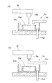
保持具洗浄手段34は、図3(a)に示すように、底付き円筒状の内槽34aとその外側の輪状の外槽34bとを有する容器において、内槽34a上方に洗浄液として超純水を供給してオーバーフローさせる配管34cを設け、外槽34b下部にオーバーフローした洗浄液を排出する配管34dを設けたものである。図2において、試料回収装置30は、回収液移動手段32により、保持具32aを基板1の外周からさらに外側にある保持具洗浄手段34の内槽34a上方にまで移動させ、図3(a)のように上下に移動させる。すなわち、保持具32aの少なくとも下端部を洗浄液に浸漬させて洗浄する。供給側の配管34cは、洗浄後の内槽34a内の洗浄液に含まれる汚染物を流入させないために、図示のように内槽34a内の洗浄液と非接触にすることが好ましい。なお、洗浄は、洗浄液を保持具32aに吹き付けて行ってもよい。この場合には、図3(b)のように、供給側の配管34cを開口が上向きになるように設け、下方から保持具32aに洗浄液を吹き付ける。
As shown in FIG. 3 (a), the holder cleaning means 34 is a container having a bottomed cylindrical
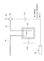
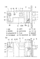
さて、保持具32aから溶液(フッ化水素酸)4を滴下するための構成について、詳細に説明する。この試料回収装置30は、図1に示すように、さらに、以下の残量検知手段81A、弁82、制御装置60などを備える。この蛍光X線分析システムが置かれる半導体製造ラインにおける窒素ガスや空気のラインが、チューブ84を経由して、容器83内に収納された溶液4を所定の圧力(例えば、ゲージ圧で0.025±0.005MPa の範囲内の圧力)で加圧し、加圧された溶液4の流路であるチューブ84は、弁82を経由して、ノズルである保持具32a(図2)に接続されている。残量検知手段81Aは、容器83内における溶液4の残量を検知する。弁82は、容器83内において所定の圧力で加圧された溶液4の流路を開閉する電磁弁である。制御装置60は、蛍光X線分析システム全体の制御装置60(図5)を兼ねており、溶液4の残量、弁82の開放時間および溶液4の滴下量の相関関係をあらかじめ記憶し、その記憶した相関関係および残量検知手段81Aにより検知された溶液の残量に基づいて、溶液4を滴下するための弁82の開放時間を決定する。
Now, a configuration for dropping the solution (hydrofluoric acid) 4 from the
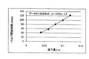
残量検知手段81Aと、溶液4の残量、弁82の開放時間および溶液4の滴下量の相関関係とについて、より具体的に説明する。例えば、容器83が満杯、つまり溶液4の残量が500ccのとき、弁(バルブ)82の開放時間y1(単位:ミリ秒)と溶液4の滴下量x1(単位:cc)の相関関係を実験から求めると、図6に示すように、次の(1)式で近似できる。
The correlation between the remaining amount detecting means 81A and the remaining amount of the
y1=1025x1−1.4 (1) y 1 = 1025x 1 −1.4 (1)
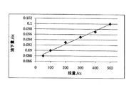
一方、弁82の開放時間が100ミリ秒のとき、溶液4の滴下量(単位:cc)と溶液4の残量(単位:cc)の相関関係を実験から求めると、図7に示すグラフが得られる。
On the other hand, when the opening time of the
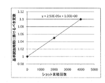
さて、1回の適切な溶液4の滴下量は100μリットル、つまり0.1ccであるが、図6、図7から明らかなように、容器83が満杯、つまり溶液4の残量が500ccのとき、適切な溶液4の滴下量0.1ccは、弁82の開放時間100ミリ秒で得られ、これを基準開放時間とする。適切な溶液4の滴下量0.1ccが維持されるとすると、溶液4の残量は、満杯状態からの溶液4の累積の滴下回数x(以下、ショット累積回数xという)から、500−0.1xとして計算でき、換言すれば、溶液4の残量は、ショット累積回数xとして検知できる。残量検知手段81Aは、このようにショット累積回数xをカウントすることにより、容器83内における溶液4の残量を検知する。適切な溶液4の滴下量0.1ccを維持するには、ショット累積回数xに応じて弁82の開放時間を基準開放時間100ミリ秒から長くする必要があるが、ショット累積回数xと弁82の開放時間を長くするために基準開放時間に掛けるべき定数の関係は、図6の相関関係つまり式(1)と図7の相関関係に基づいて得られ、図8に示すように、次の(2)式で近似できる。
Now, the appropriate drop amount of the
y=2.5×10⁻⁵×x+1 (2) y = 2.5 × 10 −5 × x + 1 (2)
つまり、適切な溶液4の滴下量0.1ccを維持するための弁82の開放時間tは、次の(3)式で表される。
That is, the opening time t of the
t=100×(2.5×10−5×x+1) (3) t = 100 × (2.5 × 10 −5 × x + 1) (3)
制御装置60は、具体的にはこの(3)式を相関関係としてあらかじめ記憶する。そして、その記憶した(3)式と、残量検知手段81Aにより検知された溶液の残量、具体的には残量検知手段81Aによりカウントされたショット累積回数xとに基づいて、適切な溶液4の滴下量0.1ccを維持するための弁82の開放時間tを決定する。
Specifically, the
このような制御により、溶液4の残量の影響を受けずに、1回の滴下量を、適切な滴下量100μリットルに対し、−10〜+0%(−10〜+0μリットル)というきわめて微量の誤差内に収めることができる。なお、この実施形態では、容器83が満杯のときに適切な溶液4の滴下量100μリットルが得られる弁82の開放時間を基準開放時間としたが、これに限られず、例えば、残量が満杯の半分になったときに適切な溶液4の滴下量100μリットルが得られる弁82の開放時間を基準開放時間として、残量が満杯の半分よりも多いときには弁82の開放時間を適切に短くし、残量が満杯の半分よりも少ないときには弁82の開放時間を適切に長くするようにしてもよい。この場合にも、溶液4の残量の影響を受けずに、1回の滴下量を、適切な滴下量100μリットルに対し、−5〜+5%(−5〜+5μリットル)というきわめて微量の誤差内に収めることができる。また、1回の適切な溶液4の滴下量は、この実施形態では100μリットルとしたが、基板1や溶液4の種類に応じて50〜200μリットル程度の範囲で変更してもよい。
By such control, the amount of one drop is not affected by the remaining amount of the
さらに、以上の説明においては、ショット累積回数xをカウントすることにより、容器83内における溶液4の残量を検知する残量検知手段81Aを用いたが、これに代えて、溶液4の残量を直接検知するレベルメータを残量検知手段81Bとして用いてもよい。
Further, in the above description, the remaining amount detecting means 81A for detecting the remaining amount of the
次に、この蛍光X線分析システムの動作について説明する。このシステムでは、前処理および分析の条件として、複数のモードがあるが、ここでは、VPD(Vapor Phase Decomposition)モードでの動作を説明する。以下の動作は、図1の制御装置60により制御される。まず、図4において、搬送装置50が、基板1を所定の投入位置から分解室21へ搬送し、基板台25に載置する。搬入の際、気相分解装置20のシャッター21a,27が自動的に開く。基板台25には、内周に下向き狭小のテーパ25aが付いているので、基板1がハンド部50a上で所定の位置から多少ずれていても、基板1を基板台25に載置するだけで、自重で滑ってはまり込むようにして適切に位置決めされるので、続く回収、分析が正確に行われる。
Next, the operation of this fluorescent X-ray analysis system will be described. In this system, there are a plurality of modes as preprocessing and analysis conditions. Here, the operation in the VPD (Vapor Phase Decomposition) mode will be described. The following operations are controlled by the
次に、シャッター21a,27が閉じて密閉された分解室21内にフッ化水素が配管22aから導入され、基板1表面に形成された酸化膜を溶解するとともに、膜の表面または膜中に存在する汚染物質などの被測定物を溶解し、配管22bから排出される。基板1表面に膜が形成されていない場合には、基板1表面に存在する被測定物が溶解される。フッ化水素導入の際、排出側の配管22bのバルブが導入側の配管22aのバルブよりも先に開くことが好ましいが、逆でも同時でもよい。このフッ化水素による気相分解は、設定により例えば10分間行われる。
Next, hydrogen fluoride is introduced from the
所定時間の気相分解が終了すると、液滴乾燥手段24により分解室21内が排気されながら窒素が流され、フッ化水素が追い出されるとともに、基板1に生じた液滴が乾燥される。これにより、以降の搬送において、液滴に搬送装置のハンド部50aが接触して腐食されることがなく、ハンド部50a上で基板1が滑って搬送が不正確になることもない。また、フッ化水素が、搬送装置50側や蛍光X線分析装置側に流入して、腐食などの原因となることもない。また、定期的に、分解室洗浄手段23により分解室21内に超純水が流されて洗浄される。このように、分解室21内の洗浄も自動化されるので、システムの操作がいっそう容易になる。
When the vapor phase decomposition for a predetermined time is completed, nitrogen is flowed while the inside of the
次に、搬送装置50が、基板1を図2の回収室31へ搬送し、基板1の中心が回転台35の回転中心に合致するように載置する。搬送の際、気相分解装置20および試料回収装置30のシャッター21a,27,31aが自動的に開閉する。このように、分解室21から回収室31への基板1の搬送も搬送装置50で行うので、人手による汚染が回避されて正しい分析ができる。続いて、試料回収装置30が、保持具32aから基板1の外周近傍に滴下した溶液4を、基板1を回転させながら、保持具32aで保持しつつ基板1上で中心まで移動させて、基板1表面に存在する被測定物(気相分解装置20により基板1表面に保持された被測定物)を回収する。ここで、溶液4の滴下量が、図1の制御装置60により前述したように制御される。
Next, the
このように、本実施形態の蛍光X線分析システムによれば、溶液4の残量、弁82の開放時間および溶液4の滴下量の相関関係をあらかじめ記憶するとともに、溶液4の残量を検知し、その検知した溶液4の残量と前記相関関係とに基づいて、溶液4を滴下するための弁82の開放時間を決定するので、溶液4の残量の影響を受けずに、所望の一定の滴下量が、例えば適切な滴下量100μリットルに対し−10〜+0%(−10〜+0μリットル)というきわめて微量の誤差内で、得られる。したがって、滴下した溶液4を基板1表面の外周からわずかにはみ出させながら、しかも基板1側面からこぼれ落ちないように、保持具32aで保持して移動させることも可能となり、円板状の基板1の側面に存在する被測定物まで含めて、被測定物の回収が正しく行われる。
As described above, according to the X-ray fluorescence analysis system of the present embodiment, the correlation between the remaining amount of the
また、回収工程における溶液4の滴下位置や保持具32aの移動経路は、前述したものに限定されず、種々考えられる。回収後、図2の保持具32aを上昇させ保持具洗浄手段34の内槽34a上方にまで移動させて上下させ、洗浄液に浸漬させて洗浄する。このように、保持具32aの洗浄も自動化されるので、システムの操作がいっそう容易になる。
In addition, the dropping position of the
次に、試料回収装置30は、基板1の中心上方にランプ33aを移動させ、被測定物を回収した溶液4を加熱して被測定物を乾燥させる。この乾燥時にも、回転台35で基板1を水平面内で回転させる。これにより、被測定物が、基板1上で偏って乾燥して拡がりすぎることがないので、いっそう正しい分析ができる。また、回収室31が分解室21の上に配置され、ファン11およびフィルター12を介して回収室31に流入した清浄な空気が、パンチング孔31bを通って分解室21の内側シャッター21aの外側へ流れ落ちるようになっているので、システム全体の設置面積が十分に小さくなるとともに、回収室31が清浄に保たれる。なお、保持具32aが被測定物を回収した溶液4の上方から退避した後であれば、保持具32aの洗浄と被測定物の乾燥は、どちらを先に行ってもよく、並行して行ってもよい。
Next, the
次に、搬送装置50が、被測定物を回収した基板1を蛍光X線分析装置の導入室のカセットへ搬送する。搬送の際、試料回収装置30のシャッター31aが自動的に開閉する。続いて、蛍光X線分析装置が全反射蛍光X線分析を行い、分析後、基板1は、搬送装置50によりもとの所定の投入位置へ搬送される。なお、最初の基板1の分析中に、次の基板の回収、その次の基板の分解を同時に行えば、全体の前処理および分析作業をいっそう迅速に行える。
Next, the
以上詳細に説明したように、本発明の蛍光X線分析用試料前処理装置またはそれを備えた蛍光X線分析システムによれば、溶液の残量の影響を受けずに、所望の一定の滴下量が得られ、被測定物の回収が正しく行われる。 As described in detail above, according to the sample pretreatment apparatus for fluorescent X-ray analysis of the present invention or the fluorescent X-ray analysis system equipped with the same, a desired constant drop can be obtained without being affected by the remaining amount of the solution. The quantity is obtained and the object to be measured is collected correctly.
1 基板
2 被測定物
4 溶液
10 試料前処理装置(気相分解装置および試料回収装置)
20 気相分解装置
21 分解室
30 試料回収装置
32a 保持具
40 蛍光X線分析装置
43 1次X線
44 蛍光X線
60 制御装置
81A,81B 残量検知手段
82 弁
83 容器
1
20 Gas-
Claims (2)
表面に被測定物が存在する基板に溶液を滴下して保持具で保持しながら基板表面で移動させ、被測定物を回収後乾燥させて基板表面に保持する試料回収装置とを備えた蛍光X線分析用試料前処理装置であって、
前記溶液を収納した容器内における溶液の残量を検知する残量検知手段と、
前記容器内において所定の圧力で加圧された前記溶液の流路を開閉する弁と、
前記溶液の残量、前記弁の開放時間および溶液の滴下量の相関関係をあらかじめ記憶し、その記憶した相関関係および前記残量検知手段により検知された溶液の残量に基づいて、前記溶液を滴下するための前記弁の開放時間を決定する制御装置とを備えた蛍光X線分析用試料前処理装置。 A vapor phase decomposition apparatus for holding a measurement object existing on the substrate surface or a surface of a film formed on the substrate surface or a measurement object existing in the film with a reactive gas in the decomposition chamber and then drying and holding on the substrate surface ,
Fluorescent X equipped with a sample recovery device that drops a solution onto a substrate on which the object to be measured is present and moves it on the surface of the substrate while holding it with a holder, collects the object to be measured, dries it, and holds it on the substrate surface A sample pretreatment device for line analysis,
A remaining amount detecting means for detecting the remaining amount of the solution in the container containing the solution;
A valve for opening and closing the flow path of the solution pressurized at a predetermined pressure in the container;
The correlation between the remaining amount of the solution, the opening time of the valve, and the dropping amount of the solution is stored in advance, and the solution is determined based on the stored correlation and the remaining amount of the solution detected by the remaining amount detecting means. A sample pretreatment device for fluorescent X-ray analysis, comprising: a control device that determines an opening time of the valve for dripping.
前記気相分解装置または試料回収装置により基板表面に保持された被測定物に1次X線を照射して発生する蛍光X線の強度を測定する蛍光X線分析装置とを備えた蛍光X線分析システム。 A sample pretreatment apparatus for fluorescent X-ray analysis according to claim 1;
Fluorescent X-ray provided with an X-ray fluorescence analyzer for measuring the intensity of fluorescent X-rays generated by irradiating the object to be measured held on the substrate surface by the vapor phase decomposition apparatus or the sample recovery apparatus with primary X-rays Analysis system.
Priority Applications (1)
| Application Number | Priority Date | Filing Date | Title |
|---|---|---|---|
| JP2009260710A JP2011106903A (en) | 2009-11-16 | 2009-11-16 | Sample pretreatment device for fluorescent x-ray analysis, and fluorescent x-ray analysis system including the same |
Applications Claiming Priority (1)
| Application Number | Priority Date | Filing Date | Title |
|---|---|---|---|
| JP2009260710A JP2011106903A (en) | 2009-11-16 | 2009-11-16 | Sample pretreatment device for fluorescent x-ray analysis, and fluorescent x-ray analysis system including the same |
Publications (1)
| Publication Number | Publication Date |
|---|---|
| JP2011106903A true JP2011106903A (en) | 2011-06-02 |
Family
ID=44230553
Family Applications (1)
| Application Number | Title | Priority Date | Filing Date |
|---|---|---|---|
| JP2009260710A Pending JP2011106903A (en) | 2009-11-16 | 2009-11-16 | Sample pretreatment device for fluorescent x-ray analysis, and fluorescent x-ray analysis system including the same |
Country Status (1)
| Country | Link |
|---|---|
| JP (1) | JP2011106903A (en) |
-
2009
- 2009-11-16 JP JP2009260710A patent/JP2011106903A/en active Pending
Similar Documents
| Publication | Publication Date | Title |
|---|---|---|
| JP3603278B2 (en) | X-ray fluorescence analysis system and program used therefor | |
| JP3584262B2 (en) | Sample pretreatment system for X-ray fluorescence analysis and X-ray fluorescence analysis system having the same | |
| KR100832107B1 (en) | Pollution testing apparatus and method, and reticle cleaning equipment and method using the apparatus | |
| TW201810480A (en) | Measuring device and method for ion contaminant on wafer surface | |
| TWI638400B (en) | Substrate processing device, substrate processing method, and memory medium | |
| US10712328B2 (en) | Analysis device | |
| JP7654100B2 (en) | SUBSTRATE PROCESSING APPARATUS AND SUBSTRATE PROCESSING METHOD | |
| CN107567652A (en) | Substrate contamination analysis device and substrate contamination analysis method | |
| KR101970338B1 (en) | Apparatus and method for analyzing surface of wafer using spinning | |
| JP2011106903A (en) | Sample pretreatment device for fluorescent x-ray analysis, and fluorescent x-ray analysis system including the same | |
| JP3629535B2 (en) | Sample pretreatment apparatus for fluorescent X-ray analysis and fluorescent X-ray analysis system provided with the same | |
| JP2006214877A (en) | Vapor phase decomposition apparatus, sample pretreatment apparatus and fluorescent X-ray analysis system using the same | |
| US9989484B2 (en) | X-ray fluorescence analyzing system | |
| US12444654B2 (en) | Systems and methods for determining flow characteristics of a fluid segment for analytic determinations | |
| TWI635550B (en) | Apparatus for analyzing substrate contamination | |
| JP3300213B2 (en) | Aerial impurity monitoring device and aerial impurity monitoring method | |
| JP5407900B2 (en) | Flow measuring device and flow measuring method | |
| KR20230038866A (en) | Method for treating a substrate and an apparatus for treating a substrate | |
| TWI693104B (en) | Substrate processing device and parts inspection method of substrate processing device | |
| JP4662531B2 (en) | Substrate processing apparatus and substrate processing method | |
| JP3811718B2 (en) | Sample collection device for X-ray fluorescence analysis | |
| JP2003098128A (en) | Sample pretreatment device for X-ray fluorescence analysis | |
| JPH08320293A (en) | Foreign object inspection method and device | |
| CN111336792B (en) | Cavity for drying micro water drops | |
| JP2023056689A (en) | Analyzer |