JP2011106484A - Parking lock device - Google Patents
Parking lock device Download PDFInfo
- Publication number
- JP2011106484A JP2011106484A JP2009259228A JP2009259228A JP2011106484A JP 2011106484 A JP2011106484 A JP 2011106484A JP 2009259228 A JP2009259228 A JP 2009259228A JP 2009259228 A JP2009259228 A JP 2009259228A JP 2011106484 A JP2011106484 A JP 2011106484A
- Authority
- JP
- Japan
- Prior art keywords
- gear
- lock
- parking
- link
- rotation
- Prior art date
- Legal status (The legal status is an assumption and is not a legal conclusion. Google has not performed a legal analysis and makes no representation as to the accuracy of the status listed.)
- Pending
Links
Images


Classifications
-
- F—MECHANICAL ENGINEERING; LIGHTING; HEATING; WEAPONS; BLASTING
- F16—ENGINEERING ELEMENTS AND UNITS; GENERAL MEASURES FOR PRODUCING AND MAINTAINING EFFECTIVE FUNCTIONING OF MACHINES OR INSTALLATIONS; THERMAL INSULATION IN GENERAL
- F16H—GEARING
- F16H63/00—Control outputs from the control unit to change-speed- or reversing-gearings for conveying rotary motion or to other devices than the final output mechanism
- F16H63/40—Control outputs from the control unit to change-speed- or reversing-gearings for conveying rotary motion or to other devices than the final output mechanism comprising signals other than signals for actuating the final output mechanisms
- F16H63/48—Signals to a parking brake or parking lock; Control of parking locks or brakes being part of the transmission
Abstract
Description
本発明は、パーキングロック装置に関するものである。 The present invention relates to a parking lock device.
従来、車両の変速装置には、シフトレバーをPレンジにしたとき、変速装置内部に設けたパーキングギアと係合し、車両が不用意に動かないようにさせるパーキングロック装置が備えられている。 2. Description of the Related Art Conventionally, a vehicle transmission device has been provided with a parking lock device that engages with a parking gear provided inside the transmission device to prevent the vehicle from moving carelessly when the shift lever is in the P range.
この種のパーキングロック装置は、例えば特許文献1で示すように、アクチュエータ(モータ)がコントロールロッドを介してディテントプレートを回転駆動させると、自動変速機制御装置とパークロッドが同時に摺動操作されるように構成されている。そして、アクチュエータの駆動によって、自動変速機制御装置がPレンジになる時に、パークロッドの先端に設けられた円錐状のロックカムが、パーキングロックポールをパーキングギアに噛合するロック位置に変位操作する。これによって、パーキングロックポールが噛合したパーキングギアは回転が禁止されて、自動変速機の出力軸の回転も規制されるようになっている。このとき、ディテントプレートの変位はローラ付き板バネによってPレンジに保持可能に構成される。 In this type of parking lock device, for example, as shown in Patent Document 1, when an actuator (motor) rotates a detent plate via a control rod, the automatic transmission control device and the park rod are simultaneously slid. It is configured as follows. When the automatic transmission control device is in the P range by driving the actuator, a conical lock cam provided at the tip of the park rod is displaced to a lock position where the parking lock pawl meshes with the parking gear. As a result, the parking gear engaged with the parking lock pole is prohibited from rotating, and the rotation of the output shaft of the automatic transmission is also restricted. At this time, the displacement of the detent plate is configured to be held in the P range by a leaf spring with a roller.
ところで、上記特許文献1のパーキングロック装置では、パーキングロックポールをロック位置に変位操作するロックカム、そのロックカムを押し引き操作するコントロールロッド、ディテントプレートの変位を規制するローラ付き板バネなどといった多数の部材を設置する必要があるため、変速ユニット全体としての小型化を阻害する傾向があった。 By the way, in the parking lock device of the above-mentioned patent document 1, a number of members such as a lock cam that displaces the parking lock pole to the lock position, a control rod that pushes and pulls the lock cam, and a leaf spring with a roller that regulates the displacement of the detent plate. Therefore, there is a tendency to hinder downsizing of the entire transmission unit.
しかも、パーキングロック装置の駆動には、比較的大きなトルクを必要とするため、一般にアクチュエータ(モータ)とコントロールロッドの間に減速比の大きな減速機構を設けている。その結果、減速機構に用いられる歯車機構は、抵効率の歯車機構となるため、必然的に大型のモータを用いなければならず、パーキングロック装置の大型化につながっていた。 Moreover, since a relatively large torque is required to drive the parking lock device, a reduction mechanism having a large reduction ratio is generally provided between the actuator (motor) and the control rod. As a result, since the gear mechanism used for the speed reduction mechanism is a low-efficiency gear mechanism, a large motor must be used, which leads to an increase in the size of the parking lock device.
また、シフトレバーがPレンジにあってパーキングロックポール、ディテントプレートがロック位置あるときに、これらパーキングロックポールや、ディテントプレートに何らかの要因でアンロック位置の方向に力が加えられた場合、アンロック位置側に回動しないように防止部材が設けられている。これら防止部材を設けることによって、部品点数が増加し、パーキングロック装置のさらなる大型化につながっていた。 Also, when the shift lever is in the P range and the parking lock pole and detent plate are in the locked position, if any force is applied to the parking lock pole or detent plate in the direction of the unlock position for any reason, the lock will be unlocked. A prevention member is provided so as not to rotate to the position side. By providing these prevention members, the number of parts increased, leading to further enlargement of the parking lock device.
本発明は、上記問題を解消するためになされたものであって、その目的は用いる部品点数を少なくでき、装置全体をより小型することができるパーキングロック装置を提供することにある。 The present invention has been made to solve the above-described problems, and an object of the present invention is to provide a parking lock device that can reduce the number of parts to be used and can further reduce the size of the entire device.
請求項1に記載の発明は、第1支軸を回転中心に回動してパーキングギアと噛合するロック位置と前記パーキングギアとの噛合が解除されるアンロック位置に回動案内されるロックポールと、駆動ギアと噛合し、その駆動ギアの正逆回転によって第2支軸を回転中心として往復回動して前記ロックポールを、前記ロック位置とロック解除位置に案内する減速ギアと、前記駆動ギアを正逆回転させるモータとを有したパーキングロック装置であって、前記駆動ギアは、その一部に無歯部を形成した欠歯車で構成し、前記減速ギアは、その円弧状の外周面の一部にギア部を形成し、そのギア部の一側に、前記ロックポールがロック位置に案内された時、前記無歯部と嵌合する第1嵌合部を、そのギア部の他側に、前記ロックポールがアンロック位置に案内された時、前記無歯部と嵌合する第2嵌合部を形成し、前記第1及び第2嵌合部と前記無歯部の各嵌合面は、前記駆動ギアに回動力が加えられたとき、前記無歯部の嵌合面が第1及び第2嵌合部の嵌合面に摺接して前記減速ギアとの噛合を許容し、前記減速ギアに回動力が加えられたとき、前記第1及び第2嵌合部の嵌合面が前記無歯部の嵌合面と当接して前記減速ギアの回転を禁止する制御面を形成した。 According to the first aspect of the present invention, the lock pole that is pivotally guided to the unlocked position where the meshing with the parking gear is released, and the lock position that meshes with the parking gear by rotating about the first support shaft. A reduction gear that meshes with the drive gear and reciprocates around the second support shaft by forward and reverse rotation of the drive gear to guide the lock pole to the lock position and the unlock position; and the drive A parking lock device having a motor for rotating the gear forward and backward, wherein the drive gear is constituted by a partial gear having a toothless part formed in a part thereof, and the reduction gear is an arc-shaped outer peripheral surface thereof A gear part is formed in a part of the gear part, and a first fitting part fitted to the toothless part when the lock pawl is guided to the lock position is provided on one side of the gear part. On the side, the lock pole is unlocked A second fitting portion that fits with the toothless portion when being guided to the drive gear, and each fitting surface of the first and second fitting portions and the toothless portion is driven by the drive gear. Is applied, the mating surface of the toothless portion is in sliding contact with the mating surfaces of the first and second mating portions to allow meshing with the reduction gear, and rotational force is applied to the reduction gear. Then, the fitting surfaces of the first and second fitting portions are in contact with the fitting surfaces of the toothless portion to form a control surface that prohibits rotation of the reduction gear.
請求項1に記載の発明によれば、第1嵌合部と無歯部a、第1及び第2嵌合部の嵌合面に形成した制御面によって、ロック位置にある減速ギアが、何らかの要因で、アンロック位置の方向に力が加えられても、アンロック位置側に回動しない。その結果、ロック位置あるロックポールがパーキングギアとの噛合が解除されることが防止される。 According to the first aspect of the present invention, the reduction gear in the locked position is somehow formed by the control surface formed on the fitting surface of the first fitting portion and the toothless portion a and the first and second fitting portions. Even if force is applied in the direction of the unlock position due to the factor, it does not rotate to the unlock position side. As a result, the lock pole at the lock position is prevented from being disengaged from the parking gear.
また、アンロック位置にある減速ギアが、何らかの要因で、ロック位置の方向に力が加えられても、ロック位置側に回動しない。その結果、アンロック位置にあるロックポールがパーキングギアと噛合されることが防止される。 Further, even if the reduction gear in the unlock position is applied in the direction of the lock position for some reason, it does not rotate to the lock position side. As a result, the lock pole in the unlock position is prevented from being engaged with the parking gear.
しかも、第1及び第2嵌合部と駆動ギアの無歯部は、減速ギアと駆動ギアの一部として一体的に形成できるので、回転防止機構のための部品点数を増加させることはなく、パーキングロック装置の小型化を図ることができる。 In addition, since the first and second fitting portions and the toothless portion of the drive gear can be integrally formed as a part of the reduction gear and the drive gear, the number of parts for the rotation prevention mechanism is not increased. The parking lock device can be downsized.
請求項2に記載の発明は、請求項1に記載のパーキングロック装置において、前記第1支軸を回転中心としてロック位置とアンロック位置との2位置間を回動する前記ロックポールは、前記減速ギアを支持する前記第2支軸を回転中心に回動する回動リンクと、前記回動リンクの先端部と前記ロックポールに先端部間をそれぞれ連結軸にて回転可能に連結する連結リンクとで4節リンク機構を構成するとともに、前記回動リンクに対して、前記ロックポールをロック位置側に回動させる弾性力を付与する弾性部材を設けた。 According to a second aspect of the present invention, in the parking lock device according to the first aspect, the lock pawl that rotates between two positions of a lock position and an unlock position with the first support shaft as a rotation center is A rotation link that rotates about the second support shaft that supports the reduction gear, and a connection link that rotatably connects the front end portion of the rotation link and the lock pole with a connection shaft between the front end portion and the lock pole. And an elastic member for providing an elastic force for rotating the lock pawl toward the lock position with respect to the rotation link.
請求項2に記載の発明によれば、ロックポールを回動させるのに効率の良い4節リンク機構を用いたので、ロックポールを回動させるのに大きなトルクを必要としない。そのため、アクチュエータを小型でき、パーキングロック装置を小型化できる。しかも、4節リンク機構と減速ギアを平行に配置できるので、組み付けスペースを少スペースにでき、パーキングロック装置全体を小型化することができる。 According to the second aspect of the present invention, since an efficient four-bar linkage mechanism is used to rotate the lock pole, a large torque is not required to rotate the lock pole. Therefore, the actuator can be downsized, and the parking lock device can be downsized. Moreover, since the four-bar linkage mechanism and the reduction gear can be arranged in parallel, the assembly space can be reduced, and the entire parking lock device can be reduced in size.
請求項3に記載の発明は、請求項2に記載のパーキングロック装置において、前記減速ギアは、前記回動リンクと前記連結リンクとを連結する前記連結軸に係合し、前記減速ギアが前記弾性部材の弾性力を付与する方向と反対方向に回動するとき、前記連結軸を介して、前記弾性部材の弾性力に抗して前記回動リンクに、前記ロックポールをアンロック位置側に回動させる回動力を付与する操作片を設けた。 According to a third aspect of the present invention, in the parking lock device according to the second aspect, the reduction gear is engaged with the connecting shaft that connects the rotating link and the connecting link, and the reduction gear is When rotating in a direction opposite to the direction in which the elastic force of the elastic member is applied, the lock pole is moved to the unlocking position side against the rotating link against the elastic force of the elastic member via the connecting shaft. An operation piece for providing rotating power to be rotated was provided.
請求項3に記載の発明によれば、駆動ギアによって、減速ギアが弾性部材の弾性力を付与する方向と反対方向のアンロック位置に回動するとき、操作片にて弾性部材の弾性力に抗して回動リンク、即ち、ロックポールをアンロック位置に回動させる。 According to the third aspect of the present invention, when the reduction gear rotates to the unlock position in the direction opposite to the direction in which the elastic force of the elastic member is applied by the drive gear, The rotation link, that is, the lock pole is rotated to the unlock position.
請求項4に記載の発明は、請求項2又は3に記載のパーキングロック装置において、前記弾性部材は、ゼンマイバネであって、前記ゼンマイバネの内側巻き端を減速ギアのボス部に係合させ、前記ゼンマイバネの外側巻き端を前記回動リンクと前記連結リンクとを連結する前記連結軸に係合させた。 According to a fourth aspect of the present invention, in the parking lock device according to the second or third aspect, the elastic member is a spring, and an inner winding end of the spring is engaged with a boss portion of a reduction gear, The outer winding end of the spring spring is engaged with the connecting shaft that connects the rotating link and the connecting link.
請求項4に記載の発明によれば、ゼンマイバネも、4節リンク機構と減速ギアに対して平行に配置できるので、組み付けスペースを少スペースにでき、パーキングロック装置全体を小型化することができる。 According to the fourth aspect of the present invention, since the mainspring can also be arranged in parallel to the four-bar linkage mechanism and the reduction gear, the assembly space can be reduced and the entire parking lock device can be reduced in size.
請求項5に記載の発明は、請求項4に記載のパーキングロック装置において、前記パーキングギアの一側に配置されるプレートに、前記モータと前記モータにて回転される前記駆動ギアを設けるとともに、前記第1支軸及び第2支軸を設け、その第1支軸に前記ロックポールを回転可能に支持し、前記第2支軸に前記減速ギア及び4節リンク機構を構成する前記回動リンクを回動可能に支持するようにした。 According to a fifth aspect of the present invention, in the parking lock device according to the fourth aspect, the plate disposed on one side of the parking gear is provided with the motor and the drive gear rotated by the motor, The first support shaft and the second support shaft are provided, the lock pole is rotatably supported on the first support shaft, and the reduction link and the four-link mechanism are configured on the second support shaft. Is supported to be rotatable.
請求項5に記載の発明によれば、パーキングギアの一側に配置されるプレートに、パーキングロック装置を構成する殆どの構成部材が集約して組み付けられるようにしたので、よりパーキングロック装置がコンパクトになり、車両の変速装置への組み付けが容易となる。 According to the fifth aspect of the present invention, since most of the structural members constituting the parking lock device are assembled and assembled on the plate disposed on one side of the parking gear, the parking lock device is more compact. Thus, the vehicle can be easily assembled to the transmission.
本発明によれば、用いる部品点数を少なくでき、装置全体をより小型することができることができる。 According to the present invention, the number of parts used can be reduced, and the entire apparatus can be further reduced in size.
(第1実施形態)
以下、本発明のパーキングロック装置の実施形態を図面に従って説明する。
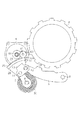
図1はパーキングロック装置の全体斜視図、図2はパーキングロック装置の分解斜視図を示す。
(First embodiment)
Hereinafter, embodiments of a parking lock device of the present invention will be described with reference to the drawings.
1 is an overall perspective view of the parking lock device, and FIG. 2 is an exploded perspective view of the parking lock device.
パーキングロック装置1は、車両に備えられた変速装置のハウジングケース内に設けられ、パーキングギア2、そのパーキングギア2と係脱するロックポール3を有している。パーキングギア2は、変速装置のハウジングケース内に貫挿されたエンジンのクランク軸(図示せず)に固着され、クランク軸と一体回転するようになっている。そして、パーキングギア2は、パーキングギア2の歯にロックポール3の係止爪3aが噛合することによって、その回転が禁止される。
The parking lock device 1 is provided in a housing case of a transmission provided in a vehicle, and includes a parking gear 2 and a
ロックポール3は、パーキングギア2に隣接配置され、変速装置のハウジングケース内に固設された中間プレート4に揺動可能に支持されている。ロックポール3は、その基端部が中間プレート4に固設した第1支持部材5に設けた第1支軸6に対して回動可能に支持され、第1支軸6の中心軸線C1を回転中心として回動可能になっている。
The
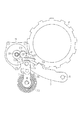
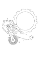
ロックポール3のパーキングギア2側の中間部には、係止爪3aが形成されている。ロックポール3は、パーキングギア2側に回動して係止爪3aが、図4に示すように、パーキングギア2と噛合する位置(以下、ロック位置という)に案内されることでパーキングギア2の回転を不能にさせるようになっている。反対に、ロックポール3は、パーキングギア2から離間する方向に回動して係止爪3aが、図3に示すように、パーキングギア2との噛合を解除する位置(以下、アンロック位置という)に案内させることでパーキングギア2の回転を可能にさせるようになっている。
A
次に、係止爪3aがパーキングギア2と噛合するロック位置と噛合解除されるロック解除位置との間で、ロックポール3を回動させる駆動機構について説明する。駆動機構は中間プレート4に設けられている。
Next, a drive mechanism for rotating the
中間プレート4の一側に設けた第2支持部材7には、第2支軸8が取着され、その第2支軸8に回動リンク9に基端部が回動可能に支持され、回動リンク9は第2支軸8の中心軸線C2を回転中心として回動可能になっている。そして、回動リンク9の先端部は、連結リンク10を介してロックポール3の先端部と連結されている。
A
詳述すると、回動リンク9の先端部と連結リンク10の一端は、第1連結軸11が貫挿され、第1連結軸11に対してそれぞれ回転可能に支持されている。一方、連結リンク10の他端とロックポール3の先端部は、第2連結軸12が貫挿され、第2連結軸12に対してそれぞれ回転可能に支持されている。
More specifically, the first connecting
これによって、中間プレート4上において、これらロックポール3、回動リンク9、連結リンク10によって、4節リンク機構が構成されている。従って、回動リンク9を、第2支軸8の中心軸線C2を回転中心として回動させると、連結リンク10を介して、ロックポール3が第1支軸6の中心軸線C1を回転中心として回動する。
Thereby, on the
そして、図3に示すアンロック位置に、ロックポール3、回動リンク9及び連結リンク10が位置した状態から、回動リンク9を、時計回り方向に、図4に示すロック位置まで回動させると、ロックポール3も連動して回動する。そして、ロックポール3の係止爪3aは、パーキングギア2との噛合が解除されたアンロック位置から噛合するロック位置に案内される。
Then, from the state where the
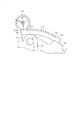
ここで、回動リンク9を、時計回り方向に、図3に示すアンロック位置から図4に示すロック位置まで回動させるとき、図5に示すように、回動リンク9と連結リンク10を回転可能に支持連結した第1連結軸11の中心軸線C3は、第2支軸8の中心軸線C2と第2連結軸12の中心軸線C4の間であって、かつ、これら中心軸線C2,C4を結ぶ直線L1を、左から右に横切るように形成されている。そして、第1連結軸11の中心軸線C3が直線L1を越えて右に位置した時、回動リンク9の先端部はロックポール3のパーキングギア2と反対側の側面3bに当接し押圧するようになっている。
Here, when the
従って、図5に示す位置(ロック位置)にあって、ロックポール3に対して、第1支軸6の中心軸線C1を回転中心として反時計回りの回動力が加えられたとき、第1連結軸11の中心軸線C3が直線L1の右側に位置しているため、ロックポール3は連結リンク10にてロックされ反時計回りの回動が禁止される。その結果、ロックポール3の係止爪3aは、パーキングギア2との噛合が解除されることはない。
Accordingly, when the counterclockwise turning force about the central axis C1 of the
反対に、図4、図5に示す位置(ロック位置)に、ロックポール3、回動リンク9及び連結リンク10が位置した状態から、回動リンク9を、反時計回り方向に、図3に示すアンロック位置まで回動させると、連結リンク10を介してロックポール3も連動する。
On the contrary, from the state where the
つまり、第1連結軸11の中心軸線C3が、回動するロックポール3の第2連結軸12の中心軸線C4を通る接線L2を右から左に越えた時、ロックポール3は、連結リンク10を介して回動リンク9の回動力によって回動する。そして、ロックポール3の係止爪3aは、パーキングギア2と噛合された位置から噛合が解除されたアンロック位置に案内される。
That is, when the central axis C3 of the first connecting
回動リンク9を回動可能に支持した第2支軸8には、減速ギアとしてのセクターギア20が回転可能に支持されている。セクターギア20は、中間プレート4と回動リンク9との間に平行に配置されている。セクターギア20は、基端ボス部21が第2支軸8に回転可能に支持され、第2支軸8の中心軸線C2を回転中心に回動するようになっている。
A
セクターギア20と第1連結軸11の間には、弾性部材としてのゼンマイバネ30が介装されている。ゼンマイバネ30は、セクターギア20の基端ボス部21を取り囲むように配置され、中心側の巻き端(内巻き端)31が基端ボス部21外周面に連結固定され、外側の巻き端(外巻き端)32が、連結リンク10から下方に突出した第1連結軸11の係止部11aに摺動可能に連結されている。
A mainspring 30 as an elastic member is interposed between the
そして、ゼンマイバネ30の外巻き端32は、ゼンマイバネ30の拡張方向の付勢力を第1連結軸11の係止部11aに付与している。つまり、ゼンマイバネ30は、第1連結軸11にゼンマイバネ30の拡張方向の付勢力を付与することによって、回動リンク9を図3において、時計回り方向(アンロック位置からロック位置方向)の回動力を常に付与している。
The outer winding
セクターギア20の側面には、ゼンマイバネ30の外巻き端32を摺動可能に連結した第1連結軸11の係止部11aを、ロックポール3側から係合する復帰操作片22が立設形成されている。復帰操作片22は、セクターギア20が図3において反時計回り方向に回動したとき、第1連結軸11の係止部11aと係合し、ゼンマイバネ30の拡張方向の付勢力に抗して回動リンク9を反時計回り方向に回動させるようになっている。
On the side surface of the
セクターギア20の先端外周面には、平歯車状のギア部23が形成されている。また、そのギア部23のパーキングギア2側の外側には、第2嵌合部としてのアンロック側嵌合凹部24が形成されているとともに、ギア部23のパーキングギア2側と反対側の外側には、第1嵌合部としてのロック側嵌合凹部25が形成されている。
A spur gear-
セクターギア20のギア部23は、中間ギア機構40を介してモータMと駆動連結されている。モータMは、中間プレート4に形成されたボス部4aに嵌合固設され、その出力軸には第1ヘリカルギアG1が外嵌固定されている。中間ギア機構40は、第2ヘリカルギアG2と平歯車状の駆動ギアG3を有し、中間プレート4に立設した支持軸41に回転可能に支持されている。第2ヘリカルギアG2と平歯車状の駆動ギアG3は、一体的に支持軸41に対して回転するように互いに連結固定されている。
The
そして、第2ヘリカルギアG2は、モータMの第1ヘリカルギアG1と噛合し、駆動ギアG3は、セクターギア20のギア部23と噛合するようになっている。従って、モータMを回転させることによって、モータMの駆動力が中間ギア機構40を介してセクターギア20に伝達され、セクターギア20は、第2支軸8を回転中心に回動する。
The second helical gear G2 meshes with the first helical gear G1 of the motor M, and the drive gear G3 meshes with the
ここで、図3に示すアンロック位置において、セクターギア20が時計回り方向に回動すると、セクターギア20に設けた復帰操作片22も時計回り方向に回動する。この時、復帰操作片22に係合していた第1連結軸11(回動リンク9)は、ゼンマイバネ30の拡張方向の付勢力によって押圧され、第2支軸8を回転中心に時計回り方向に回動する。この回動に連動してロックポール3も回動する。そして、セクターギア20がさらに回動して回動リンク9が、図3に示すアンロック位置から図4に示すロック位置まで回動すると、ロックポール3の係止爪3aは、パーキングギア2と噛合する位置に案内される。
Here, when the
なお、ロックポール3の係止爪3aが、時計回り方向に回動してパーキングギア2と噛合する際、パーキングギア2の回動停止位置によって、図6に示すように、パーキングギア2の歯の歯面2aに当接し、歯溝に噛合しない場合がある。
When the locking
このロックポール3の係止爪3aがパーキングギア2の歯面2aに当接した状態においては、ロックポール3は、時計回り方向の回動は禁止されるが、セクターギア20は、駆動ギアG3によって、時計回り方向に回動し続ける。
In a state where the locking
つまり、セクターギア20に設けた復帰操作片22が第1連結軸11の係止部11aから離間し、第1連結軸11の係止部11aを残して復帰操作片22が時計回り方向に回動することになる。その結果、ロックポール3の係止爪3aが、パーキングギア2の歯面2aをゼンマイバネ30の拡張方向の付勢力にて押し続けた状態(以下、これを「待ち状態」という)で、ロックポール3は回動停止している。
That is, the
この「待ち状態」において、駐車された車両に対して、路面の起伏、あるいは、悪意で車両を移動させようとする力に基づいてエンジンのクランク軸に僅かな回転力が加えられると、パーキングギア2がいずれかの方向に回動する。その結果、ロックポール3の係止爪3aは、ゼンマイバネ30の拡張方向の付勢力によってパーキングギア2の歯溝に押し込まれ噛合し、自動的に図4に示すロック位置となる。
In this “waiting state”, if a slight turning force is applied to the crankshaft of the engine on the parked vehicle based on the road surface undulation or the force to move the vehicle maliciously, the parking gear 2 rotates in either direction. As a result, the locking
反対に、図4に示すロック位置において、セクターギア20が反時計回り方向に回動すると、セクターギア20に設けた復帰操作片22も反時計回り方向に回動する。この時、復帰操作片22は、この回動によりに第1連結軸11と係合し、第1連結軸11(回動リンク9)をゼンマイバネ30の拡張方向の付勢力に抗して、第2支軸8を回転中心に反時計回り方向に回動させる。この回動に連動してロックポール3も反時計回り方向に回動する。そして、セクターギア20がさらに回動して回動リンク9が、図3に示すアンロック位置まで回動すると、ロックポール3の係止爪3aは、パーキングギア2との噛合が解除された位置に案内される。
On the other hand, when the
セクターギア20のギア部23と噛合する駆動ギアG3は、図7に示すように、外周面の一部に無歯部G3aを有する欠歯歯車であって、無歯部G3aを除く外周面に形成された歯の歯数は、セクターギア20に形成したギア部23の歯溝(アンロック側嵌合凹部24及びロック側嵌合凹部25とそれぞれ隣接する歯溝26,27を含む)の数と同じにしている。そして、駆動ギアG3は、図3に示すアンロック位置にあるとき、その無歯部G3aがギア部23のアンロック側嵌合凹部24と嵌合し、図4に示すロック位置にあるとき、その無歯部G3aがロック側嵌合凹部25と嵌合するように予め組み付けられている。
As shown in FIG. 7, the drive gear G3 that meshes with the
ここで、図3及び図4に示す状態で、アンロック側嵌合凹部24及びロック側嵌合凹部25と嵌合して部分の駆動ギアG3の無歯部G3aの制御面としての外周面は、支持軸41の中心軸線C5を中心とした半径Rの円弧面である。尚、半径Rは、支持軸41の中心軸線C5から駆動ギアG3の歯面までの長さと一致させている。そして、アンロック側嵌合凹部24及びロック側嵌合凹部25の内側に凹設された制御面としての内周面は、前記無歯部G3aの円弧面が摺動可能な、図3及び図4に示す状態で、支持軸41の中心軸線C5を中心とした半径の円弧面にて形成されている。
Here, in the state shown in FIG. 3 and FIG. 4, the outer peripheral surface as the control surface of the toothless portion G3a of the drive gear G3 of the portion engaged with the unlocking-side
また、アンロック側嵌合凹部24及びロック側嵌合凹部25は、その周方向の長さは無歯部G3aの周方向の長さより短く形成されているとともに、その周方向の両端部がギア部23の各歯と同じ高さになるようにそれぞれ形成されている。
Further, the unlocking side
一方、駆動ギアG3の無歯部G3aは、図3及び図4に示すアンロック側嵌合凹部24及びロック側嵌合凹部25の内周面と摺接している部分から外れる位置から駆動ギアG3の歯に至る外周面はその曲率半径を小さくし駆動ギアG3の歯溝に収束するように形成されている。
On the other hand, the toothless portion G3a of the drive gear G3 is driven from a position that is disengaged from the portions that are in sliding contact with the inner peripheral surfaces of the unlock side
つまり、図3に示すアンロック位置にあって、駆動ギアG3の無歯部G3aがアンロック側嵌合凹部24と嵌合しているとき、駆動ギアG3が支持軸41を回転中心として反時計回り方向に回転すると、ギア部23の最初の歯がアンロック側嵌合凹部24の側壁とギア部23の最初の歯とで形成された歯溝26に噛合して、セクターギア20は第2支軸8を回転中心として時計回り方向に回動を開始する。
That is, when the toothless portion G3a of the drive gear G3 is engaged with the unlock-side
そして、図4に示すロック位置に到達して、駆動ギアG3の最後の歯がセクターギア20のギア部23の最後の歯とロック側嵌合凹部25の側壁とで形成された歯溝27との噛合が外れると、駆動ギアG3の無歯部G3aがロック側嵌合凹部25と嵌合する。その結果、セクターギア20は時計回り方向への回動を停止され、ロック位置に保持される。
Then, when the lock position shown in FIG. 4 is reached, the last tooth of the drive gear G3 is a tooth groove 27 formed by the last tooth of the
反対に、図4に示すロック位置にあって、駆動ギアG3の無歯部G3aがロック側嵌合凹部25と嵌合しているとき、駆動ギアG3が支持軸41を回転中心として時計回り方向に回転すると、ギア部23の最初の歯がロック側嵌合凹部25の側壁とギア部23の最初の歯とで形成された歯溝27に噛合して、セクターギア20は第2支軸8を回転中心として反時計回り方向に回動を開始する。
On the other hand, when the toothless portion G3a of the drive gear G3 is in the lock position shown in FIG. 4 and is engaged with the lock-side
そして、図3に示すアンロック位置に到達して、駆動ギアG3の最後の歯がセクターギア20のギア部23の最後の歯とアンロック側嵌合凹部24側壁とで形成された歯溝26との噛合が外れると、駆動ギアG3の無歯部G3aがアンロック側嵌合凹部24と嵌合する。その結果、セクターギア20は時計回り方向への回動を停止されアンロック位置に保持される。
Then, when the unlock position shown in FIG. 3 is reached, the last tooth of the drive gear G3 is a
そして、図4に示すロック位置にあって、駆動ギアG3の無歯部G3aがロック側嵌合凹部25と嵌合している状態で、何らかの原因でセクターギア20に反時計回り方向の外力が加えられたとする。セクターギア20は反時計回り方向に回動しようとするが、ロック側嵌合凹部25の歯溝27側の端部が、駆動ギアG3の無歯部G3aの外周面(円弧面)の当たり、回動不能にする。つまり、駆動ギアG3の時計回り方向の回転によってのみセクターギア20は反時計回り方向に回動が可能になる。
In the locked position shown in FIG. 4, the external force in the counterclockwise direction is applied to the
同様に、図3に示すアンロック位置にあって、駆動ギアG3の無歯部G3aがアンロック側嵌合凹部24と嵌合している状態で、何らかの原因でセクターギア20に時計回り方向の外力が加えられたとする。セクターギア20は時計回り方向に回動しようとするが、アンロック側嵌合凹部24の歯溝26側の端部が、駆動ギアG3の無歯部G3aの外周面(円弧面)の当たり、回動不能にする。つまり、駆動ギアG3の反時計回り方向の回転によってのみセクターギア20は時計回り方向に回動が可能になる。
Similarly, in the unlock position shown in FIG. 3, the toothed portion G3a of the drive gear G3 is engaged with the unlock-side
尚、本実施形態では、モータMの回転軸に設けた第1ヘリカルギアG1と中間ギア機構40の第2ヘリカルギアG2の間で得られる減速比を2:15とし、中間ギア機構40の駆動ギアG3とセクターギア20に形成したギア部23の間で得られる減速比を18:170として、全体としての減速比は1:71としている。
In this embodiment, the reduction ratio obtained between the first helical gear G1 provided on the rotating shaft of the motor M and the second helical gear G2 of the
これは、停止中のモータMがゼンマイバネ30に対する付勢力によって逆転回転されうる程度の小さな減速比である。
以上詳述したように、本実施形態によれば、以下に示す効果が得られる。
This is a reduction ratio that is small enough that the stopped motor M can be rotated in reverse by the biasing force against the
As described above in detail, according to the present embodiment, the following effects can be obtained.
(1)本実施形態では、ロックポール3、回動リンク9、連結リンク10とで4節リンク機構を形成した。そして、ゼンマイバネ30にてロックポール3をロック位置に常に回動させる方向に回動力を付与した回動リンク9に対して、セクターギア20で回動させるようにした。
(1) In this embodiment, the
つまり、4節リンク機構とその4節リンク機構とセクターギア20を平行に配設してロックポール3をロック位置とアンロック位置に回動させようにしたので、組み付けスペースを少スペースにでき、パーキングロック装置全体を小型化することができる。
In other words, since the four-bar linkage mechanism, the four-bar linkage mechanism and the
しかも、ロックポール3を回動させるのに効率の良い4節リンク機構を用いたので、ロックポール3を回動させるのに大きなトルクを必要としない。そのため、モータMを小型でき、その分パーキングロック装置を小型化できる。
In addition, since an efficient four-bar linkage mechanism is used to rotate the
(2)本実施形態では、セクターギア20のギア部23の一側にロック側嵌合凹部25を形成し、ギア部23と噛合する駆動ギアG3に無歯部G3aを形成した。そして、ロック側嵌合凹部25と無歯部G3aの嵌合面を、駆動ギアG3の無歯部G3aがロック側嵌合凹部25と嵌合している状態で、セクターギア20に反時計回り方向の外力が加えられたとき、ロック側嵌合凹部25の歯溝27側の端部が、駆動ギアG3の無歯部G3aの外周面(円弧面)に当たって回動不能になるように形成した。
(2) In this embodiment, the lock-side
従って、ロック位置にあるセクターギア20が、何らかの要因で、アンロック位置の方向に力が加えられても、アンロック位置側に回動しない。その結果、ロックポール3がパーキングギア2との噛合が解除されることが防止される。
Therefore, even if the
しかも、この回転防止機構のロック側嵌合凹部25と無歯部G3aを、セクターギア20と駆動ギアG3にそれぞれ一体的に形成したので、回転防止機構のための部品点数の増加はなく、パーキングロック装置の小型化を図ることができる。
In addition, since the lock-side
(3)また、本実施形態では、セクターギア20のギア部23の他側に、駆動ギアG3の無歯部G3aと嵌合するアンロック側嵌合凹部24を形成した。そして、アンロック側嵌合凹部24と無歯部G3aの嵌合面を、駆動ギアG3の無歯部G3aがアンロック側嵌合凹部24と嵌合している状態で、セクターギア20に時計回り方向の外力が加えられたとき、アンロック側嵌合凹部24の歯溝26側の端部が、駆動ギアG3の無歯部G3aの外周面(円弧面)に当たって回動不能になるように形成した。
(3) Moreover, in this embodiment, the unlocking side fitting recessed
従って、アンロック位置にあるセクターギア20が、何らかの要因で、ロック位置の方向に力が加えられても、ロック位置側に回動しない。その結果、ロックポール3がパーキングギア2と噛合されることが防止される。
Therefore, even if the
しかも、この回転防止機構のアンロック側嵌合凹部24と無歯部G3aを、同様に、セクターギア20と駆動ギアG3にそれぞれ一体的に形成したので、回転防止機構のための部品点数の増加はなく、パーキングロック装置の小型化を図ることができる。
Moreover, since the unlocking-side
(3)また、本実施形態では、ロックポール3を常にロック位置側に付勢する弾性部材をゼンマイバネ30で構成した。従って、ゼンマイバネ30は、ロックポール3、回動リンク9、連結リンク10及びセクターギア20に対して平行に配置でき、組み付けスペースを少スペースにでき、パーキングロック装置全体をさらに小型化することができる。
(3) Moreover, in this embodiment, the elastic member which always urges | biases the
(4)本実施形態では、パーキングギア2を除いて、パーキングロック装置1の殆どの部材を、中間プレート4に、組み付けるように構成した。パーキングロック装置1の構成部材を組み付けた中間プレート4を事前に用意し、その中間プレート4を変速装置に組み付けるだけで、パーキングロック装置が簡単に組み付けられる。
(4) In the present embodiment, except for the parking gear 2, most of the members of the parking lock device 1 are configured to be assembled to the
尚、上記実施形態は以下のように変更してもよい。
・上記実施形態では、駆動ギアG3を平歯状の欠歯歯車、セクターギア20のギア部23の歯を平歯状にした。これを、それぞれヘリカルギアにして実施してもよい。
In addition, you may change the said embodiment as follows.
In the above embodiment, the drive gear G3 is a spur gear with a spur tooth and the
・上記実施形態では、第1ヘリカルギアG1及び第2ヘリカルギアG2を平歯車で実施してもよい。
・上記実施形態では、パーキングギア2を、変速装置に貫挿されたエンジンのクランク軸に固着したパーキングロック装置に具体化した。これを、変速装置の出力軸にパーキングギア2を固着したパーキングロック装置に応用してもよい。
In the above embodiment, the first helical gear G1 and the second helical gear G2 may be implemented with spur gears.
In the above embodiment, the parking gear 2 is embodied as a parking lock device that is fixed to the crankshaft of the engine that is inserted through the transmission. This may be applied to a parking lock device in which the parking gear 2 is fixed to the output shaft of the transmission.
1…パーキングロック装置、2…パーキングギア、2a…歯面、3…ロックポール、3a…係止爪、4…中間プレート(プレート)、5…第1支持部材、6…第1支軸、7…第2支持部材、8…第2支軸、9…回動リンク、10…連結リンク、11…第1連結軸(連結軸)、11a…係止部、12…第2連結軸(連結軸)、20…セクターギア(減速ギア)、21…基端ボス部(ボス部)、22…復帰操作片(操作片)、23…ギア部、24…アンロック側嵌合凹部(第2嵌合部)、25…ロック側嵌合凹部(第1嵌合部)、26,27…歯溝、30…ゼンマイバネ(弾性部材)、31…内巻き端、32…外巻き端、40…中間ギア機構、41…支持軸、G1…第1ヘリカルギア、G2…第2ヘリカルギア、G3…駆動ギア、G3a…無歯部、G3a…無歯部、M…モータ、C1〜C5…中心軸線。
DESCRIPTION OF SYMBOLS 1 ... Parking lock apparatus, 2 ... Parking gear, 2a ... Tooth surface, 3 ... Lock pole, 3a ... Locking claw, 4 ... Intermediate plate (plate), 5 ... 1st support member, 6 ... 1st spindle, 7 DESCRIPTION OF SYMBOLS ... 2nd support member, 8 ... 2nd spindle, 9 ... Turning link, 10 ... Connection link, 11 ... 1st connection shaft (connection shaft), 11a ... Locking part, 12 ... 2nd connection shaft (connection shaft) ), 20 ... Sector gear (reduction gear), 21 ... Proximal boss part (boss part), 22 ... Return operation piece (operation piece), 23 ... Gear part, 24 ... Unlock side fitting recess (second fitting) Part), 25 ... Lock-side fitting recess (first fitting part), 26, 27 ... Tooth groove, 30 ... Spring spring (elastic member), 31 ... Inner winding end, 32 ... Outer winding end, 40 ...
Claims (5)
駆動ギアと噛合し、その駆動ギアの正逆回転によって第2支軸を回転中心として往復回動して前記ロックポールを、前記ロック位置とロック解除位置に案内する減速ギアと、
前記駆動ギアを正逆回転させるモータと
を有したパーキングロック装置であって、
前記駆動ギアは、その一部に無歯部を形成した欠歯車で構成し、
前記減速ギアは、その円弧状の外周面の一部にギア部を形成し、そのギア部の一側に、前記ロックポールがロック位置に案内された時、前記無歯部と嵌合する第1嵌合部を、そのギア部の他側に、前記ロックポールがアンロック位置に案内された時、前記無歯部と嵌合する第2嵌合部を形成し、
前記第1及び第2嵌合部と前記無歯部の各嵌合面は、前記駆動ギアに回動力が加えられたとき、前記無歯部の嵌合面が第1及び第2嵌合部の嵌合面に摺接して前記減速ギアとの噛合を許容し、前記減速ギアに回動力が加えられたとき、前記第1及び第2嵌合部の嵌合面が前記無歯部の嵌合面と当接して前記減速ギアの回転を禁止する制御面を形成したことを特徴とするパーキングロック装置。 A lock pole that rotates around the first support shaft and meshes with a parking gear, and a lock pole that is guided to rotate to an unlock position where meshing with the parking gear is released;
A reduction gear that meshes with the drive gear and reciprocally rotates around the second support shaft by forward and reverse rotation of the drive gear to guide the lock pole to the lock position and the unlock position;
A parking lock device having a motor for rotating the drive gear forward and backward,
The drive gear is constituted by a partial gear having a toothless part formed in a part thereof,
The reduction gear has a gear portion formed on a part of its arc-shaped outer peripheral surface. When the lock pole is guided to the lock position on one side of the gear portion, the reduction gear is fitted with the toothless portion. 1 fitting part is formed on the other side of the gear part, and when the lock pawl is guided to the unlocked position, a second fitting part is formed for fitting with the toothless part,
The fitting surfaces of the first and second fitting parts and the toothless part are the first and second fitting parts when the rotational force is applied to the drive gear. When the rotational force is applied to the reduction gear, the fitting surfaces of the first and second fitting portions are fitted to the toothless portion. A parking lock device characterized in that a control surface is formed in contact with the mating surface and prohibits rotation of the reduction gear.
前記第1支軸を回転中心としてロック位置とアンロック位置との2位置間を回動する前記ロックポールは、前記減速ギアを支持する前記第2支軸を回転中心に回動する回動リンクと、前記回動リンクの先端部と前記ロックポールに先端部間をそれぞれ連結軸にて回転可能に連結する連結リンクとで4節リンク機構を構成するとともに、
前記回動リンクに対して、前記ロックポールをロック位置側に回動させる弾性力を付与する弾性部材を設けたことを特徴とするパーキングロック装置。 The parking lock device according to claim 1,
The lock pole that rotates between two positions of a lock position and an unlock position with the first support shaft as a rotation center is a rotation link that rotates about the second support shaft that supports the reduction gear. And a four-link mechanism comprising a tip end of the pivot link and a connecting link that rotatably connects the tip end portion to the lock pole by a connecting shaft,
The parking lock device according to claim 1, wherein an elastic member for applying an elastic force for rotating the lock pole toward the lock position is provided for the rotation link.
前記減速ギアは、前記回動リンクと前記連結リンクとを連結する前記連結軸に係合し、前記減速ギアが前記弾性部材の弾性力を付与する方向と反対方向に回動するとき、前記連結軸を介して、前記弾性部材の弾性力に抗して前記回動リンクに、前記ロックポールをアンロック位置側に回動させる回動力を付与する操作片を設けたことを特徴とするパーキングロック装置。 The parking lock device according to claim 2,
The reduction gear engages with the connection shaft that connects the rotation link and the connection link, and when the reduction gear rotates in a direction opposite to the direction in which the elastic force of the elastic member is applied, the connection A parking lock characterized in that an operating piece for providing a turning force for rotating the lock pole to the unlock position side is provided on the rotation link against an elastic force of the elastic member via a shaft. apparatus.
前記弾性部材は、ゼンマイバネであって、前記ゼンマイバネの内側巻き端を減速ギアのボス部に係合させ、前記ゼンマイバネの外側巻き端を前記回動リンクと前記連結リンクとを連結する前記連結軸に係合させたことを特徴とするパーキングロック装置。 In the parking lock device according to claim 2 or 3,
The elastic member is a spring, and the inner winding end of the spring is engaged with a boss portion of a reduction gear, and the outer winding end of the spring is connected to the connecting shaft that connects the rotating link and the connecting link. A parking lock device characterized by being engaged.
前記パーキングギアの一側に配置されるプレートに、前記モータと前記モータにて回転される前記駆動ギアを設けるとともに、前記第1支軸及び第2支軸を設け、その第1支軸に前記ロックポールを回転可能に支持し、前記第2支軸に前記減速ギア及び4節リンク機構を構成する前記回動リンクを回動可能に支持するようにしたことを特徴とするパーキングロック装置。 In the parking lock device according to claim 4,
The plate disposed on one side of the parking gear is provided with the motor and the drive gear rotated by the motor, and is provided with the first support shaft and the second support shaft. A parking lock device, wherein a lock pole is rotatably supported, and the rotation link constituting the reduction gear and the four-bar linkage mechanism is rotatably supported on the second support shaft.
Priority Applications (1)
| Application Number | Priority Date | Filing Date | Title |
|---|---|---|---|
| JP2009259228A JP2011106484A (en) | 2009-11-12 | 2009-11-12 | Parking lock device |
Applications Claiming Priority (1)
| Application Number | Priority Date | Filing Date | Title |
|---|---|---|---|
| JP2009259228A JP2011106484A (en) | 2009-11-12 | 2009-11-12 | Parking lock device |
Publications (1)
| Publication Number | Publication Date |
|---|---|
| JP2011106484A true JP2011106484A (en) | 2011-06-02 |
Family
ID=44230191
Family Applications (1)
| Application Number | Title | Priority Date | Filing Date |
|---|---|---|---|
| JP2009259228A Pending JP2011106484A (en) | 2009-11-12 | 2009-11-12 | Parking lock device |
Country Status (1)
| Country | Link |
|---|---|
| JP (1) | JP2011106484A (en) |
Cited By (2)
| Publication number | Priority date | Publication date | Assignee | Title |
|---|---|---|---|---|
| JP2015090184A (en) * | 2013-11-06 | 2015-05-11 | アイシン精機株式会社 | Shift device |
| CN110159755A (en) * | 2019-05-29 | 2019-08-23 | 中国第一汽车股份有限公司 | A kind of parking execution device |
-
2009
- 2009-11-12 JP JP2009259228A patent/JP2011106484A/en active Pending
Cited By (2)
| Publication number | Priority date | Publication date | Assignee | Title |
|---|---|---|---|---|
| JP2015090184A (en) * | 2013-11-06 | 2015-05-11 | アイシン精機株式会社 | Shift device |
| CN110159755A (en) * | 2019-05-29 | 2019-08-23 | 中国第一汽车股份有限公司 | A kind of parking execution device |
Similar Documents
| Publication | Publication Date | Title |
|---|---|---|
| US6729203B2 (en) | Bicycle gear shifter having separate shift control members for cable pull and release | |
| TWI495595B (en) | Bicycle sprocket with gear | |
| JP5212729B2 (en) | Parking lock device | |
| JP5064780B2 (en) | Screw driver | |
| JP2006322489A (en) | Electric parking lock device | |
| US11473678B2 (en) | Electric park lock actuator limited rotary disconnect | |
| JP6303917B2 (en) | Automatic transmission parking lock device | |
| JP2010007823A (en) | Gear locking device | |
| JP5182991B2 (en) | Fork shaft drive for transmission | |
| JP2005535812A (en) | Door latch actuator | |
| US20050126329A1 (en) | Shifter for a bicycle transmission | |
| JP2011106484A (en) | Parking lock device | |
| JP2011143893A (en) | Parking lock device | |
| JP5203004B2 (en) | Unidirectional coupling device and correction device having the same | |
| JP2012072854A (en) | Electric actuator for parking lock | |
| JP2005059844A (en) | Twist grip shift control device for bicycle using parallel gears | |
| JP2004113039A (en) | Fishing reel | |
| JP3593842B2 (en) | Parking mechanism | |
| JP4336714B2 (en) | Rotating actuator for adjuster mechanism of vehicle seat | |
| JP7312519B2 (en) | vehicle door stop | |
| JPS6133207B2 (en) | ||
| JP2011179186A (en) | Electric lock | |
| JP2005273818A (en) | Operating device for automatic transmission for vehicle | |
| EP2111754B1 (en) | Fishing spinning reel | |
| CN214661967U (en) | Lock plate for transmission, transmission for vehicle, and vehicle |