JP2011106298A - Power generator - Google Patents
Power generator Download PDFInfo
- Publication number
- JP2011106298A JP2011106298A JP2009259508A JP2009259508A JP2011106298A JP 2011106298 A JP2011106298 A JP 2011106298A JP 2009259508 A JP2009259508 A JP 2009259508A JP 2009259508 A JP2009259508 A JP 2009259508A JP 2011106298 A JP2011106298 A JP 2011106298A
- Authority
- JP
- Japan
- Prior art keywords
- power generation
- blade
- wind
- mode
- generation means
- Prior art date
- Legal status (The legal status is an assumption and is not a legal conclusion. Google has not performed a legal analysis and makes no representation as to the accuracy of the status listed.)
- Abandoned
Links
Images


Classifications
-
- Y—GENERAL TAGGING OF NEW TECHNOLOGICAL DEVELOPMENTS; GENERAL TAGGING OF CROSS-SECTIONAL TECHNOLOGIES SPANNING OVER SEVERAL SECTIONS OF THE IPC; TECHNICAL SUBJECTS COVERED BY FORMER USPC CROSS-REFERENCE ART COLLECTIONS [XRACs] AND DIGESTS
- Y02—TECHNOLOGIES OR APPLICATIONS FOR MITIGATION OR ADAPTATION AGAINST CLIMATE CHANGE
- Y02E—REDUCTION OF GREENHOUSE GAS [GHG] EMISSIONS, RELATED TO ENERGY GENERATION, TRANSMISSION OR DISTRIBUTION
- Y02E10/00—Energy generation through renewable energy sources
- Y02E10/50—Photovoltaic [PV] energy
-
- Y—GENERAL TAGGING OF NEW TECHNOLOGICAL DEVELOPMENTS; GENERAL TAGGING OF CROSS-SECTIONAL TECHNOLOGIES SPANNING OVER SEVERAL SECTIONS OF THE IPC; TECHNICAL SUBJECTS COVERED BY FORMER USPC CROSS-REFERENCE ART COLLECTIONS [XRACs] AND DIGESTS
- Y02—TECHNOLOGIES OR APPLICATIONS FOR MITIGATION OR ADAPTATION AGAINST CLIMATE CHANGE
- Y02E—REDUCTION OF GREENHOUSE GAS [GHG] EMISSIONS, RELATED TO ENERGY GENERATION, TRANSMISSION OR DISTRIBUTION
- Y02E10/00—Energy generation through renewable energy sources
- Y02E10/70—Wind energy
- Y02E10/72—Wind turbines with rotation axis in wind direction
Abstract
Description
本発明は、自然エネルギーを利用した発電装置に関する。 The present invention relates to a power generation device using natural energy.
従来より、自然エネルギーを利用し、様々な方法で電力を得る方法が開発されている。その代表的な方法として、太陽光を受けることで発電を行う太陽光発電、および、風力を受けることで発電を行う風力発電、などがある。
しかしながら、日本の気候は欧米と比較して風向きが変化しやすく、また風速も安定していないため、風力発電装置だけで安定した電力を供給することは困難である。また一方、太陽光発電においても、天候の影響や日周運動の影響を直接受けるため、太陽光発電装置だけで安定した電力を供給することは困難である。
2. Description of the Related Art Conventionally, methods for obtaining electric power using various methods using natural energy have been developed. Typical methods include solar power generation that generates power by receiving sunlight, and wind power generation that generates power by receiving wind power.
However, in Japan's climate, the direction of the wind is likely to change compared to Europe and the United States, and the wind speed is not stable. Therefore, it is difficult to supply stable power only with a wind power generator. On the other hand, solar power generation is also directly affected by weather and diurnal motion, so it is difficult to supply stable power using only a solar power generation device.
そのため、風力発電装置と太陽光発電装置を組み合わせることで、お互いに発電効率を補完するハイブリッド発電装置の研究もなされている。例えば、特許文献1には、風力発電モードと、風力発電用のブレードを広げる事により、表面に設けられた反射面で太陽光を集光して太陽光発電を行う太陽光発電モードとを切り替えるハイブリッド発電装置が記載されている。
Therefore, research on hybrid power generators that complement each other's power generation efficiency by combining wind power generators and solar power generators has also been made. For example,
しかしながら、上記の先行文献においては、風力発電モードと太陽光発電モードとを切り替えるために、ブレードを開閉させる必要がある。そのため、迅速に切り替えることは難しく、またその切り替え動作には多大なエネルギー消費を伴うことになる。 However, in the above-described prior art, it is necessary to open and close the blade in order to switch between the wind power generation mode and the solar power generation mode. Therefore, it is difficult to switch quickly, and the switching operation involves a great amount of energy consumption.
本発明は、上記の問題を解決するためになされたものであり、風力発電と太陽光発電を迅速に切り替え、もしくは風力発電と太陽光発電を併用して同時に発電を行う事が可能な発電装置を提供することを目的とする。
The present invention has been made to solve the above problems, and can quickly switch between wind power generation and solar power generation, or can simultaneously generate power using wind power generation and solar power generation in combination. The purpose is to provide.
上記課題を解決するため、請求項1の発明は、発電装置であって、翼状体である複数のブレードと、前記ブレードがその先端部に配置され、前記ブレードが風を受けることにより回転する軸と、前記軸と接続され、前記軸が回転する事により電力を発生させる風力発電手段と、前記ブレードの主面上に配置され、太陽光を受光することにより電力を発生させる太陽光発電手段と、前記太陽光発電手段よりも、前記風力発電手段を優先して電力を発生させる第1モードと、前記軸を固定し、前記太陽光発電手段により電力を発生させる第2モードとを、選択的に切り替える制御部と、を備えることを特徴とする。
In order to solve the above-mentioned problem, the invention of
請求項2の発明は、請求項1に記載の発電装置において、前記ブレードを、前記軸に対して直交する方向を中心軸として回転させるブレード回転機構をさらに備え、前記制御手段は、前記ブレード回転機構を制御することにより、前記第1モードを選択した場合は、前記ブレードが風を受けることにより前記軸が回転するように前記ブレード回転機構を制御し、前記第2モードを選択した場合は、前記ブレードの主面上に配置された前記太陽光発電手段が太陽光を受光して電力を発生させるように、前記ブレード回転機構を制御することを特徴とする。
According to a second aspect of the present invention, in the power generation device according to the first aspect, the blade further includes a blade rotation mechanism that rotates the blade about a direction orthogonal to the axis as a central axis, and the control means is configured to rotate the blade. When the first mode is selected by controlling the mechanism, the blade rotation mechanism is controlled so that the shaft rotates when the blade receives wind, and when the second mode is selected, The blade rotating mechanism is controlled so that the solar power generation means disposed on the main surface of the blade receives sunlight to generate electric power.
請求項3の発明は、請求項1または請求項2に記載の発電装置において、前記風力発電手段を、鉛直方向を中心軸として回転させる風力発電手段回転機構をさらに備え、前記制御手段は、前記風力発電手段回転機構を制御することにより、前記第1モードを選択した場合は、前記軸の前記ブレード側端が風上方向を向くように前記風力発電手段回転機構を制御し、前記第2モードを選択した場合は、前記ブレードの主面上に配置された前記太陽光発電手段が太陽の方角に向くように前記風力発電手段回転機構を制御することを特徴とする。
A third aspect of the present invention is the power generation apparatus according to the first or second aspect, further comprising a wind power generation unit rotating mechanism that rotates the wind power generation unit about a vertical direction as a central axis, and the control unit includes the control unit, When the first mode is selected by controlling the wind power generation means rotation mechanism, the wind power generation means rotation mechanism is controlled so that the blade side end of the shaft faces the windward direction, and the second mode Is selected, the wind power generation means rotating mechanism is controlled so that the solar power generation means disposed on the main surface of the blade faces the direction of the sun.
請求項4の発明は、請求項1ないし請求項3のいずれかに記載の発電装置において、前記制御手段は、前記ブレードに作用する風速を検出し、当該風速が所定の値以上である場合に前記第1モードを選択することを特徴とする。
According to a fourth aspect of the present invention, in the power generation apparatus according to any one of the first to third aspects, the control means detects a wind speed acting on the blade, and the wind speed is equal to or higher than a predetermined value. The first mode is selected.
本発明では、風力発電手段と太陽光発電手段とを備えているため、いずれか一方でしか発電が行えない天候や状況においても、発電方法を切り替えることにより、電力を供給することが可能となる。 In the present invention, since the wind power generation means and the solar power generation means are provided, it is possible to supply electric power by switching the power generation method even in a weather or a situation where power generation is possible only in one of them. .
特に、請求項2の発明によれば、風力発電に用いる軸に対してブレードを回転させることが可能となる。これにより、風力発電を優先して行う第1モードでは、風速に対応した適切な角度にブレードを回転させ、また、太陽光発電を行う第2モードでは、太陽の方角に太陽光発電手段を向けることが可能となり、効率的な発電を行うことが可能となる。 In particular, according to the invention of claim 2, the blade can be rotated with respect to the shaft used for wind power generation. Thereby, in the first mode in which wind power generation is prioritized, the blade is rotated to an appropriate angle corresponding to the wind speed. In the second mode in which solar power generation is performed, the solar power generation means is directed toward the sun. Therefore, efficient power generation can be performed.
特に、請求項3の発明によれば、風力発電手段自体を回転させることが可能となる。これにより、第1モードでは風上にブレードを向けることが可能となり、第2モードでは、太陽光パネルを太陽の方角に向けることが可能となる。 In particular, according to the invention of claim 3, it is possible to rotate the wind power generation means itself. Thereby, in the first mode, the blade can be directed to the windward, and in the second mode, the solar panel can be directed toward the sun.
特に、請求項4の発明によれば、風速が所定の値以上である場合には第1モードを優先することで、発電量を向上させることが可能となる。
In particular, according to the invention of claim 4, when the wind speed is equal to or higher than a predetermined value, the power generation amount can be improved by prioritizing the first mode.
本発明の実施形態に係る発電装置1は、屋外に設置され、主として風力によって発電を行う発電装置である。
The
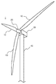
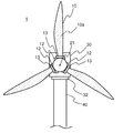
図1は、本発明の第1の実施形態に係る発電装置1の概略を示す図である。
発電装置1は、3枚のブレード10、ロータヘッド20、ナセル30、タワー40を備える発電装置である。ブレード10は主に鉄やアルミの骨格を備え、最大幅約4m、長さ約25mの長尺の翼状部材であり、先端に向かうにつれて細くなる、先細り形状を有する。
FIG. 1 is a diagram showing an outline of a
The
ロータヘッド20は、3枚のブレード10をその円周上に等間隔に配置する部材である。ブレード10は翼状となっているため、等間隔に配置された3枚のブレード10が風を受けることにより、ロータヘッド20を中心として回転する。
The
ナセル30は、内部に図示しない発電機を備える。またナセル30の内部の発電機とロータヘッド20はギヤボックス等を介して回動可能に接続されている。そのため、ロータヘッド20が回転することにより、ナセル30の内部に配置された発電機に回転運動が伝達し、その力で発電を行う。なお、本実施例における発電機は、最大発電量が1MWhである。
The
タワー40は、ナセル30を地上約40mの高さに保持するための土台である。このようにナセル30を上空に配置することにより、地上よりも風を受けやすくし、また長尺であるブレードの回転移動領域を確保することが可能となる。また、タワー40の内部は空洞となっており、発電機にて発電された電力を地上に配置された整流装置(図示省略)に送電する送電線が内蔵される。
The
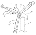
図2は、前述のロータヘッド20部分を拡大した図である。なお、ナセル30およびタワー40は仮想線で描いている。
FIG. 2 is an enlarged view of the
ブレード10は、ブレード軸11を中心として、後述のブレード回転機構12によりロータヘッド20に対して回転される(図中の回転矢印)。これは主として、風速に応じて発電に適する角度に各ブレード10を回転させるための動作であり、以後、ブレード制御と称する。また、ブレード回転機構12により回転された、ブレード10のロータヘッド20に対する角度を、ブレード角と称する。
The
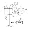
図3は、図2のA−A断面にてブレード10を切断した断面図である。なお、図示の都合上、切断されたブレード10以外のブレード10は図示を省略する。また、図3は切断されたブレード10がロータヘッド20に対して水平方向に位置した時点での図である。
3 is a cross-sectional view of the
ブレード10の断面は、風向に対して若干傾斜している。また、風向の上流側の面に比べて下流側の面が、丸みを帯びた形状となっており、下流側の面を主面10aと称する。このような形状、および角度に配置することにより、風向上流方向から風を受けると、図の矢印方向(紙面下向き)方向に揚力が発生し、ブレード10に対して下方向の力が発生する。その力をロータヘッド20により回転力に変換する。
The cross section of the
また、ブレード10は、ブレード回転機構12によって、仮想線で示すように所定のブレード角に主面10aの向きを変更することが可能となっている(ブレード制御)。
Further, the
ロータヘッド20はロータ軸21を中心として、前述のブレード10に発生する揚力を受けて回転する。またロータヘッド20の回転力は、伝達部材22を介してナセル30内部の発電機に伝達される。
The
一方ナセル30は、タワー40の上面に配置されたナセル回転機構32によってタワー40上に支持されている。ナセル回転機構32は、鉛直方向(地面に対して垂直)であるナセル軸31を中心として、3枚のブレード10が風向に対して略垂直になるようにナセル30を回転させる機構である。以後、ナセル回転機構による回転制御を、ヨーイング制御と称する。
On the other hand, the
前述のブレード回転機構12、および、ナセル回転機構32は、制御部90と電気的に接続配線されている。なお、制御部90に関しては後述する。
The
次に、図4を用いて、ブレード10の詳細を説明する。図4はブレード10を、主面10aに対して垂直な方向から見た図である。なお、ナセル30は仮想線で示す。
Next, details of the
ブレード10の主面10aの表面には、太陽光発電パネル50が配置されている。太陽光発電パネル50は、多結晶シリコン型太陽光発電素子が用いられ、太陽光を照射されることにより起電力を発生させる。ブレード10の主面10aに配置された複数の太陽光発電パネル50は、隣接する太陽光発電パネル50と電気的に配線され、主面10a全体として電力を供給する構成となっている。なお、図では途中で図示は省略されているが、太陽光発電パネル50は、ブレード10の先端部まで配置されている。各太陽光発電パネル50は、約1m角の薄板形状であり、1枚のパネルでの最大発電量は100Whである。この太陽光発電パネル50が1枚のブレードに80枚配置されており、1枚のブレードでの最大発電量は、8kWhである。
A photovoltaic
主面10aで発生した電力は、送電線51を介してロータヘッド20に伝送される。ロータヘッド20内では、他の2枚のブレード10で発生した電力も同様に送電線51を介して伝送され、ロータヘッド20の伝達部材22の内部を通って、接点52に供給される。接点52に供給された電力は、ブラシ53によって受電され、最終的にタワー下部の整流回路(図示せず)まで送電される。
The electric power generated on the
ここで、接点52は、ロータヘッド20および伝達部材22の回転に伴って回転する部材である。回転する接点52に対してブラシ53はナセル30内で固定されており、接点52はブラシ53に対して摺動しつつ回転することで、電力をブラシ53に供給する部材である。
Here, the
なお、太陽光発電パネル50は、実施例である多結晶シリコン型太陽光発電素子以外にも様々な素子を用いる事が可能である。例えば、単結晶シリコン型太陽光発電素子、色素増感型太陽光発電素子、薄膜太陽光発電素子などが適宜用いられる。
The solar
また、ブレード10がブレード回転機構12と接続される部分(根元の部分)にはフランジ13が形成されている。フランジ13はブレード10と一体に形成されており、発電装置1の設置時にボルト等の締結部材によりブレード回転機構12と締結される。そして、ブレード10の破損時などは、フランジ13部にてブレード回転機構12とブレード10とが分離され、修理、交換などが行われる。
Further, a
次に、制御部90の説明を行う。図5は、制御部90の構成を模式的に表す図である。
Next, the
制御部90は、演算部91、環境計測部92、タイマー部93、ブレード制御部94、ヨーイング制御部95を備える。演算部91は、一般的なCPU(中央演算装置)などが用いられても良いが、基板上に形成された電子回路等が用いられても良い。環境計測部92は、風向風速計81、照度計82と通信を行い、演算部91にデータとして送信する。
The
風向風速計81、および照度計82はナセル30に内蔵されたセンサーで、それぞれ、ナセル30の位置における風向、風速、太陽光の照度を計測する。なお、風向風速計81としては、プロペラ形(風車形)風向風速計や、超音波式風向風速計など、さまざまな手段を用いることが可能である。また、照度計82としては、フォトレジスタやフォトダイオードを用いて光電効果を利用して太陽光の照度を計測する手段などが用いられる。
The
タイマー部93は、日付および時刻のデータを演算部91にデータとして送信する。
The
ブレード制御部94は、演算部91によって計算されたブレード角になるように、ブレード回転機構12に対して指令を送る手段であり、具体的にはモータのドライバ等が用いられる。
The
またヨーイング制御部95は、演算部91によって計算された角度にナセル30を回転させるよう、ナセル回転機構32に対して指令を送る手段であり、具体的にはモータのドライバ等が用いられる。
The
次に、制御部90の動作を、図6のフローチャートを用いて説明する。
Next, operation | movement of the
タイマー部93から、所定の時刻になったことを示すデータが出力されると、制御部90は発電装置1の制御を開始する(ステップS10)。本実施例の場合は、10分に一度、以下の切り替え制御を行う例を示す。
When data indicating that the predetermined time has come is output from the
まず制御部90は、風向風速計81からナセル30の位置における風向および風速を計測し、環境計測部92を介して演算部91に出力する(ステップS11)。演算部91は、入力された風速データを所定の規定値と比較する(ステップS12)。ここでは、風速が3m/sec以上となると(ステップS12においてYes)、発電装置1を風力発電モードに切り替えて制御を行う。これは、太陽光発電パネル50の発電量(最大値で8kWh×3=24kWh)に比較して風力発電での発電量は1MWhであるため、風力発電が可能と判断した場合は優先的に風力発電を行うためである。
First, the
風力発電モードでは、まず環境測定部92により計測された風速に対応する角度となるようにブレード制御が行われる(ステップS21)。具体的には、演算部91は、風向風速計81にて計測された風速に応じて、ロータヘッド20に対する各ブレード10の角度(ブレード角)を演算する。そして、ブレード制御部94に対して、演算結果を出力する。ブレード制御部94は、入力された演算結果に応じて、ブレード回転機構12に信号を出力し、各ブレード10のブレード角を変更する。
In the wind power generation mode, blade control is first performed so that the angle corresponds to the wind speed measured by the environment measurement unit 92 (step S21). Specifically, the
風速発電モードにおけるブレード角とは、計測された風速において最適な回転量が得られる角度である。そして風速が強すぎる場合には、ブレード10の破損を防止するためにブレード10を風向に平行な方向に待避させる制御も含む。
The blade angle in the wind speed power generation mode is an angle at which an optimum amount of rotation is obtained at the measured wind speed. When the wind speed is too strong, the control includes retracting the
続いて、制御部90は風向風速計81により計測された風向に向けて、ヨーイング制御を行う(ステップS22)。具体的には、演算部91は風向風速計81にて計測された風向に対して垂直な方向にロータヘッド20のロータ軸21が向くように、ナセル30の回転量を演算する。そして、ヨーイング制御部95に対して演算結果を出力する。ヨーイング制御部95は、入力された演算結果に応じて、ナセル回転機構32に信号を出力し、ナセル30の角度を変更する。
Subsequently, the
その後、制御部90は選択されたモードで発電を継続する(ステップS15)。
Thereafter, the
なお、風力発電モードの場合であっても、太陽光発電パネル50に太陽光が照射すると、ブレード10aからは電力が発生する。その電力は、接点52、およびブラシ53を経由して整流回路に送電することが可能となる。しかし、接点52とブラシ53とが接触することによる摩擦抵抗を考慮し、接点52とブラシ53が離間していてもよい。
Even in the wind power generation mode, when the solar
図6に戻り、風速が3m/secよりも小さい場合(ステップS12においてNo)、制御部90は照度計82によって照度を計測し、環境測定部92を介して演算部91に出力する(ステップS13)。演算部91は、入力された照度データを所定の規定値と比較する(ステップS14)。本実施例の場合、照度が20,000ルクス以上となると(ステップS14においてYes)、発電装置1を太陽光発電モードに切り替えて制御を行う。
Returning to FIG. 6, when the wind speed is less than 3 m / sec (No in step S12), the
太陽光発電モードでは、まず太陽光発電に対応する角度となるように、ブレード制御が行われる(ステップS31)。具体的には、演算部91は、ロータヘッド20のロータ軸21に対して各ブレード10の主面10aが垂直となるように、ブレード角を演算し、演算結果をブレード制御部94に出力する。ブレード制御部94は、入力された演算結果に応じて、ブレード回転機構12に信号を出力し、ブレード角を変更する。
In the solar power generation mode, blade control is first performed so that the angle corresponds to solar power generation (step S31). Specifically, the
また、太陽光発電モードの場合、伝達部材22は、ブレード10のうち一つが鉛直方向を向く角度まで回転し、その後、図示しないロック機構により回転しないようにロックされる。
In the case of the solar power generation mode, the
続いて、制御部90はタイマー部93から出力された時刻に基づいてヨーイング制御を行う(ステップS32)。具体的には、演算部91はタイマー部93から出力された時刻から、太陽光Lの照射する方角を演算する。そして、算出された方角にロータ軸21が向くように、ナセル30の回転量を演算する。そして、ヨーイング制御部95に対して演算結果を出力する。ヨーイング制御部95は、入力された演算結果に応じて、ナセル回転機構32に信号を出力し、ナセル30の角度を変更する。
Subsequently, the
その後、制御部90は選択されたモードで発電を継続する(ステップS15)。
Thereafter, the
なお、風速が小さくても、照度が小さい場合(ステップS14でNo)、発電装置1は風力発電モードにて発電を行う。
Note that, even if the wind speed is low, if the illuminance is low (No in step S14), the
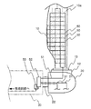
図7は、発電装置1が太陽光発電モードの場合の、太陽光Lの方角から見た発電装置1を示す図である。図7に示すように、3枚のブレード10の主面10aはそれぞれ、太陽光Lからみて垂直となる角度に配置されている。そして、ロータ軸21が太陽光Lの方角に向けられている。なお、厳密には太陽光Lの高度によって、主面10aと太陽光Lは垂直ではないが、ここでは太陽光Lの水平方向成分に対して垂直となるように制御される。
FIG. 7 is a diagram illustrating the
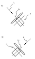
図8a)、および図8b)は、発電装置1が太陽光発電モードの場合の、発電装置1と太陽光Lの方角との関係を示す模式図である。発電装置1が太陽光発電モードを続ける場合(例えば、無風の晴天時など)、制御部90はタイマー部93から出力される時刻に応じてナセル回転機構32を制御し、ロータ軸21を太陽光Lの日周運動の方角に合わせて追尾移動させる。
FIGS. 8 a) and 8 b) are schematic diagrams showing the relationship between the
以上のように、風向風速データおよび照度データに基づいて風量発電モードと太陽光発電モードとを切り替え、それぞれの発電モードにとって最適な方向にブレード制御およびヨーイング制御を行う事により、風速の大小に関わらず、また、照度の大小に関わらず最適な発電方法を選択することが可能となる。 As described above, the wind power generation mode and the solar power generation mode are switched based on the wind direction wind speed data and the illuminance data, and blade control and yawing control are performed in the optimum direction for each power generation mode. In addition, it is possible to select an optimal power generation method regardless of the level of illuminance.
また、太陽光発電モードにおいては、太陽の日周運動に合わせて太陽光発電パネルを配向することが可能となるため、従来の太陽光発電装置に比べ、発電効率を向上させることが可能となる。
Moreover, in the photovoltaic power generation mode, it is possible to orient the photovoltaic power generation panel in accordance with the diurnal movement of the sun, so that it is possible to improve the power generation efficiency as compared with the conventional photovoltaic power generation apparatus. .
次に、本発明の第2の実施形態に係る発電装置1aについて説明を行う。発電装置1aは、太陽光発電モードにおいて太陽光Lに対するロータヘッド20との向き、および各ブレード10のブレード角が、前述の発電装置1と相違する。風力発電モードに関しては同様であるため、説明は割愛する。
Next, the
図9は、本発明の第2の実施形態に係る発電装置1aが太陽光発電モードの場合の、太陽光Lの方角から見た発電装置1aを示す図である。
FIG. 9 is a diagram showing the
図9に示すように、3枚のブレード10の主面10aはそれぞれ、ロータ軸21に対して平行となるように配向(ブレード制御)される。また、太陽光Lが照射する方向に対して、ロータ軸21が垂直となるように、ナセル30が配向(ヨーイング制御)されている。そのため、鉛直方向に配置されたブレード10の正面、および、手前側に配置されたブレードの上面に対して太陽光Lが照射される。
As shown in FIG. 9, the
図10a)、および図10b)は、発電装置1aが太陽光発電モードの場合の、発電装置1aと太陽光Lの方角との関係を示す模式図である。
FIGS. 10 a) and 10 b) are schematic diagrams showing the relationship between the
制御部90はタイマー部93から出力される時刻に応じてナセル回転機構32を制御し、ロータ軸21を太陽光Lの日周運動の方角に対して垂直な方向に配向し、追尾させる。
The
第1の実施形態である発電装置1では、太陽光Lの高度が高い(例えば夏など)場合、全体として水平方向を向いているブレード10の主面10aとのなす角度が大きくなるため、太陽光発電の効率が低下する、という恐れがある。一方、第2の実施形態である発電装置1aは、太陽光Lの高度が高い場合であっても、図9において斜め手前に配向しているブレード10aによって発電効率を高く維持することが可能となる。そのため、発電に寄与するブレードの枚数は発電装置1と比較して少ないものの、全体としては発電効率を高めることが可能となる。
In the
また、太陽光Lの方角に対するヨーイング制御は、上述の実施形態に限定されない。例えば、第1の実施形態である発電装置1、および第2の実施形態である発電装置1aの中間的な配置であってもよい。図11は第3の実施形態である発電装置1bを示す図である。
Moreover, yawing control with respect to the direction of sunlight L is not limited to the above-mentioned embodiment. For example, an intermediate arrangement of the
発電装置1bは、太陽光Lの照射する方角に対して45°傾いてヨーイング制御されている。ブレード10は、太陽光Lの方角および高度に合わせて、ブレード制御されている。このように斜め方向から太陽光Lが照射することにより、3枚のブレードは全て太陽光Lを受光することが可能である。また、ブレード制御およびヨーイング制御を適宜行うことにより、太陽光Lの高度および方角に追尾させることが可能となる。
The
同様に、上述の第1の実施形態である発電装置1においても、第3の実施形態である発電装置1bのようにブレード制御を行うことにより、太陽光Lの高度に合わせたブレード制御が可能となる。具体的には、発電装置1において斜め下方に配向されている2枚のブレード10の主面10aは、各々ブレード制御することにより、太陽光Lの高度に近い角度に制御することが可能となり、更なる発電効率の向上が可能となる。
Similarly, in the
このように、上述の第1ないし第3の実施形態のような制御方法は、発電方法の切り替え時にいずれか1つを選択されてもよいし、それぞれの方法を実測し、最適な方法を選択されてもよい。
As described above, any one of the control methods as in the first to third embodiments described above may be selected at the time of switching the power generation method, or each method is actually measured and the optimum method is selected. May be.
また、上述の第1ないし第3の実施形態では、ブレード10の枚数が3枚である実施形態を示したが、これに限られるものではない。具体的には、ブレード10の枚数は4枚以上でもよい。
In the first to third embodiments described above, the embodiment in which the number of
また、上述の第1ないし第3の実施形態では、ロータ軸21が水平方向であったが、これに限られるものではない。ロータ軸を垂直方向に配置された垂直配置型の風力発電装置においても、本発明を適用することは可能である。
In the first to third embodiments described above, the
また、上述の第1ないし第3の実施形態において、ナセル30は水平方向の回転駆動のみを行ったが、これに限られるものではない。具体的には、ナセル回転機構32だけではなく、ナセル30の垂直方向の角度(仰角)を制御する機構を備えてもよい。このような構成にすることにより、季節による太陽光Lの高度変化に追従して制御することが可能となり、更なる発電効率の向上が可能となる。
Further, in the first to third embodiments described above, the
また、上述の第1ないし第3の実施形態に記載された、風力発電モードと太陽光発電モードとを切り替えるための風速および照度の所定値は一例であり、発電装置における出力によって適宜最適な値を選択することが可能である。
Further, the predetermined values of the wind speed and illuminance for switching between the wind power generation mode and the solar power generation mode described in the first to third embodiments are merely examples, and are appropriately optimized depending on the output of the power generation device. Can be selected.
1、1a、1b ・・・ 発電装置
10 ・・・ ブレード
11 ・・・ ブレード軸
12 ・・・ ブレード回転機構
20 ・・・ ロータヘッド
21 ・・・ ロータ軸
30 ・・・ ナセル
31 ・・・ ナセル軸
32 ・・・ ナセル回転機構
40 ・・・ タワー
50 ・・・ 太陽光発電パネル
81 ・・・ 風向風速計
82 ・・・ 照度計
90 ・・・ 制御部
DESCRIPTION OF
Claims (4)
翼状体である複数のブレードと、
前記ブレードがその先端部に配置され、前記ブレードが風を受けることにより回転する軸と、
前記軸と接続され、前記軸が回転する事により電力を発生させる風力発電手段と、
前記ブレードの主面上に配置され、太陽光を受光することにより電力を発生させる太陽光発電手段と、
前記太陽光発電手段よりも、前記風力発電手段を優先して電力を発生させる第1モードと、前記軸を固定し、前記太陽光発電手段により電力を発生させる第2モードとを、選択的に切り替える制御部と、
を備えることを特徴とする発電装置。
A power generator,
A plurality of blades that are wings,
The blade is disposed at a tip thereof, and a shaft that rotates when the blade receives wind;
Wind power generating means connected to the shaft and generating electric power by rotating the shaft;
Solar power generation means disposed on the main surface of the blade and generating electric power by receiving sunlight,
A first mode in which electric power is generated in preference to the wind power generation means over the solar power generation means and a second mode in which the shaft is fixed and electric power is generated by the solar power generation means are selectively used. A control unit for switching;
A power generation device comprising:
前記ブレードを、前記軸に対して直交する方向を中心軸として回転させるブレード回転機構をさらに備え、
前記制御手段は、前記ブレード回転機構を制御することにより、前記第1モードを選択した場合は、前記ブレードが風を受けることにより前記軸が回転するように前記ブレード回転機構を制御し、前記第2モードを選択した場合は、前記ブレードの主面上に配置された前記太陽光発電手段が太陽光を受光して電力を発生させるように、前記ブレード回転機構を制御することを特徴とする発電装置。
The power generator according to claim 1,
A blade rotation mechanism for rotating the blade around a direction orthogonal to the axis as a central axis;
When the first mode is selected by controlling the blade rotation mechanism, the control means controls the blade rotation mechanism so that the shaft rotates when the blade receives wind, When the two-mode is selected, the blade rotating mechanism is controlled so that the solar power generation means disposed on the main surface of the blade receives sunlight and generates electric power. apparatus.
前記風力発電手段を、鉛直方向を中心軸として回転させる風力発電手段回転機構をさらに備え、
前記制御手段は、前記風力発電手段回転機構を制御することにより、前記第1モードを選択した場合は、前記軸の前記ブレード側端が風上方向を向くように前記風力発電手段回転機構を制御し、前記第2モードを選択した場合は、前記ブレードの主面上に配置された前記太陽光発電手段が太陽の方角に向くように前記風力発電手段回転機構を制御することを特徴とする発電装置。
In the electric power generating apparatus of Claim 1 or Claim 2,
A wind power generation means rotating mechanism for rotating the wind power generation means about a vertical direction as a central axis;
When the first mode is selected by controlling the wind power generation unit rotation mechanism, the control unit controls the wind power generation unit rotation mechanism so that the blade side end of the shaft faces the windward direction. When the second mode is selected, the wind power generation means rotating mechanism is controlled so that the solar power generation means arranged on the main surface of the blade is directed toward the sun. apparatus.
前記制御手段は、前記ブレードに作用する風速を検出し、当該風速が所定の値以上である場合に前記第1モードを選択することを特徴とする発電装置。 In the electric power generating apparatus in any one of Claim 1 thru | or 3,
The control unit detects a wind speed acting on the blade, and selects the first mode when the wind speed is equal to or higher than a predetermined value.
Priority Applications (1)
| Application Number | Priority Date | Filing Date | Title |
|---|---|---|---|
| JP2009259508A JP2011106298A (en) | 2009-11-13 | 2009-11-13 | Power generator |
Applications Claiming Priority (1)
| Application Number | Priority Date | Filing Date | Title |
|---|---|---|---|
| JP2009259508A JP2011106298A (en) | 2009-11-13 | 2009-11-13 | Power generator |
Publications (2)
| Publication Number | Publication Date |
|---|---|
| JP2011106298A true JP2011106298A (en) | 2011-06-02 |
| JP2011106298A5 JP2011106298A5 (en) | 2012-07-05 |
Family
ID=44230052
Family Applications (1)
| Application Number | Title | Priority Date | Filing Date |
|---|---|---|---|
| JP2009259508A Abandoned JP2011106298A (en) | 2009-11-13 | 2009-11-13 | Power generator |
Country Status (1)
| Country | Link |
|---|---|
| JP (1) | JP2011106298A (en) |
Cited By (9)
| Publication number | Priority date | Publication date | Assignee | Title |
|---|---|---|---|---|
| JP2013016526A (en) * | 2011-06-10 | 2013-01-24 | Ikuaki Washimi | Solar battery motor and drive unit using the same |
| EP2599998A2 (en) | 2011-11-25 | 2013-06-05 | Lech Wojtasik | Photovoltaic blade for wind turbine |
| JP2014095318A (en) * | 2012-11-08 | 2014-05-22 | Sekisei Kk | Hybrid power generator device with wind power generation and solar power generation |
| KR101472383B1 (en) * | 2013-10-08 | 2014-12-12 | 한국지질자원연구원 | Hybrid power generating system |
| JP2016056705A (en) * | 2014-09-06 | 2016-04-21 | 株式会社ドクター中松創研 | Solar/wind hybrid power generation device |
| CN107905947A (en) * | 2017-11-02 | 2018-04-13 | 江苏燕山光伏设备有限公司 | A kind of solar wind force composite type power generator |
| KR101941909B1 (en) * | 2017-12-18 | 2019-01-24 | 정태일 | Wind power and photovoltaic power generation module using solar cell with concentrator as blade |
| CN109611276A (en) * | 2018-08-12 | 2019-04-12 | 贵州省剑河民族中学 | A kind of novel solar power generation windmill |
| US11174837B2 (en) | 2016-06-02 | 2021-11-16 | Wobben Properties Gmbh | Method of controlling a wind turbine and wind turbine |
Citations (1)
| Publication number | Priority date | Publication date | Assignee | Title |
|---|---|---|---|---|
| JP2003206850A (en) * | 2002-01-17 | 2003-07-25 | Hideyasu Ikeda | Power generator with windmill combined with solar cell |
-
2009
- 2009-11-13 JP JP2009259508A patent/JP2011106298A/en not_active Abandoned
Patent Citations (1)
| Publication number | Priority date | Publication date | Assignee | Title |
|---|---|---|---|---|
| JP2003206850A (en) * | 2002-01-17 | 2003-07-25 | Hideyasu Ikeda | Power generator with windmill combined with solar cell |
Cited By (9)
| Publication number | Priority date | Publication date | Assignee | Title |
|---|---|---|---|---|
| JP2013016526A (en) * | 2011-06-10 | 2013-01-24 | Ikuaki Washimi | Solar battery motor and drive unit using the same |
| EP2599998A2 (en) | 2011-11-25 | 2013-06-05 | Lech Wojtasik | Photovoltaic blade for wind turbine |
| JP2014095318A (en) * | 2012-11-08 | 2014-05-22 | Sekisei Kk | Hybrid power generator device with wind power generation and solar power generation |
| KR101472383B1 (en) * | 2013-10-08 | 2014-12-12 | 한국지질자원연구원 | Hybrid power generating system |
| JP2016056705A (en) * | 2014-09-06 | 2016-04-21 | 株式会社ドクター中松創研 | Solar/wind hybrid power generation device |
| US11174837B2 (en) | 2016-06-02 | 2021-11-16 | Wobben Properties Gmbh | Method of controlling a wind turbine and wind turbine |
| CN107905947A (en) * | 2017-11-02 | 2018-04-13 | 江苏燕山光伏设备有限公司 | A kind of solar wind force composite type power generator |
| KR101941909B1 (en) * | 2017-12-18 | 2019-01-24 | 정태일 | Wind power and photovoltaic power generation module using solar cell with concentrator as blade |
| CN109611276A (en) * | 2018-08-12 | 2019-04-12 | 贵州省剑河民族中学 | A kind of novel solar power generation windmill |
Similar Documents
| Publication | Publication Date | Title |
|---|---|---|
| JP2011106298A (en) | Power generator | |
| EP2400153B1 (en) | Methods and systems for operating a wind turbine | |
| US7952215B2 (en) | Wind turbine generator, wind turbine generator system, and power generation control method of wind turbine generator | |
| US8622698B2 (en) | Rotor-sector based control of wind turbines | |
| US9372201B2 (en) | Yaw and pitch angles | |
| JP2011106298A5 (en) | ||
| CN101451503A (en) | Wind generator with movable sails | |
| US20140154075A1 (en) | Power production of wind turbines | |
| US9234498B2 (en) | High efficiency wind turbine | |
| CN104018996B (en) | A kind of blade of wind-driven generator for automatically adjusting front face area | |
| CN201420654Y (en) | Wind driven generator with automatic adjustable blade length | |
| Liu et al. | Modeling, simulation, hardware implementation of a novel variable pitch control for H-type vertical axis wind turbine | |
| KR101656478B1 (en) | Wind turbine generator | |
| KR100986155B1 (en) | Vertical type wind power generator of high efficient | |
| CN101871431A (en) | Cage type fan blade wind driven generator | |
| KR200454230Y1 (en) | Generator using solar and wind power | |
| CN106936372B (en) | A kind of wind light mutual complementing integral type electrification structure | |
| CA2975109C (en) | Solar and wind energy collection system and method | |
| KR101203160B1 (en) | Windmill with solar-cell panel | |
| JP2008150963A (en) | Vertical axis lift utilizing type counter-rotating wind turbine generator | |
| JP2004068622A (en) | Power generating device and rotor of wind mill | |
| TWI730337B (en) | Control method of wind power generation device | |
| KR20100121917A (en) | Structure for establishing vertical axis type wind power generation | |
| CN101922417A (en) | Method and system for generating by utilizing wind power of sails | |
| KR101064357B1 (en) | Power genertator which use vertical 3-phases blade |
Legal Events
| Date | Code | Title | Description |
|---|---|---|---|
| RD02 | Notification of acceptance of power of attorney |
Free format text: JAPANESE INTERMEDIATE CODE: A7422 Effective date: 20120323 |
|
| A621 | Written request for application examination |
Free format text: JAPANESE INTERMEDIATE CODE: A621 Effective date: 20120515 |
|
| A521 | Request for written amendment filed |
Free format text: JAPANESE INTERMEDIATE CODE: A523 Effective date: 20120517 |
|
| A977 | Report on retrieval |
Free format text: JAPANESE INTERMEDIATE CODE: A971007 Effective date: 20130220 |
|
| A131 | Notification of reasons for refusal |
Free format text: JAPANESE INTERMEDIATE CODE: A131 Effective date: 20130312 |
|
| A762 | Written abandonment of application |
Free format text: JAPANESE INTERMEDIATE CODE: A762 Effective date: 20130402 |