JP2011104073A - Blood pressure measuring apparatus and blood pressure measuring method - Google Patents
Blood pressure measuring apparatus and blood pressure measuring method Download PDFInfo
- Publication number
- JP2011104073A JP2011104073A JP2009261583A JP2009261583A JP2011104073A JP 2011104073 A JP2011104073 A JP 2011104073A JP 2009261583 A JP2009261583 A JP 2009261583A JP 2009261583 A JP2009261583 A JP 2009261583A JP 2011104073 A JP2011104073 A JP 2011104073A
- Authority
- JP
- Japan
- Prior art keywords
- blood pressure
- measurement
- sensor
- transmission unit
- pressure
- Prior art date
- Legal status (The legal status is an assumption and is not a legal conclusion. Google has not performed a legal analysis and makes no representation as to the accuracy of the status listed.)
- Granted
Links
- 0 CCCCNCC* Chemical compound CCCCNCC* 0.000 description 1
Images


Classifications
-
- A—HUMAN NECESSITIES
- A61—MEDICAL OR VETERINARY SCIENCE; HYGIENE
- A61B—DIAGNOSIS; SURGERY; IDENTIFICATION
- A61B5/00—Measuring for diagnostic purposes; Identification of persons
- A61B5/02—Detecting, measuring or recording pulse, heart rate, blood pressure or blood flow; Combined pulse/heart-rate/blood pressure determination; Evaluating a cardiovascular condition not otherwise provided for, e.g. using combinations of techniques provided for in this group with electrocardiography or electroauscultation; Heart catheters for measuring blood pressure
- A61B5/021—Measuring pressure in heart or blood vessels
- A61B5/022—Measuring pressure in heart or blood vessels by applying pressure to close blood vessels, e.g. against the skin; Ophthalmodynamometers
-
- A—HUMAN NECESSITIES
- A61—MEDICAL OR VETERINARY SCIENCE; HYGIENE
- A61B—DIAGNOSIS; SURGERY; IDENTIFICATION
- A61B2560/00—Constructional details of operational features of apparatus; Accessories for medical measuring apparatus
- A61B2560/02—Operational features
- A61B2560/0223—Operational features of calibration, e.g. protocols for calibrating sensors
-
- A—HUMAN NECESSITIES
- A61—MEDICAL OR VETERINARY SCIENCE; HYGIENE
- A61B—DIAGNOSIS; SURGERY; IDENTIFICATION
- A61B2560/00—Constructional details of operational features of apparatus; Accessories for medical measuring apparatus
- A61B2560/02—Operational features
- A61B2560/0242—Operational features adapted to measure environmental factors, e.g. temperature, pollution
- A61B2560/0247—Operational features adapted to measure environmental factors, e.g. temperature, pollution for compensation or correction of the measured physiological value
- A61B2560/0257—Operational features adapted to measure environmental factors, e.g. temperature, pollution for compensation or correction of the measured physiological value using atmospheric pressure
Abstract
Description
本発明は、血圧測定装置及び血圧測定方法に関するものである。 The present invention relates to a blood pressure measurement device and a blood pressure measurement method.
2008年度の医療点数の変更で、24時間血圧計が日本で始めて保険点数化された。特定の日時における単一の血圧測定値だけでは高血圧かどうかの正しい診断はできない。ということが医学的・医療行政に認められたということである。高血圧を理解するうえで非常に画期的なことであり、従来の血圧管理を超えた新世代の血圧管理が必用になりつつあることを示すものである。 With the change in medical scores in 2008, the 24-hour sphygmomanometer was the first insurance score in Japan. A single blood pressure measurement at a specific date and time cannot make a correct diagnosis of hypertension. That means that it was approved by the medical and medical administration. This is a very breakthrough in understanding hypertension and indicates that a new generation of blood pressure management beyond the conventional blood pressure management is becoming necessary.
すなわち血圧値は時々刻々変動しており、この変動を的確に把握し従来の血圧管理ではできなかった管理をすることによって、今以上に循環器系の疾患を減らし、今後の長寿社会で個人のQOLを高め、国全体の総医療費を引き下げ、医療財政を破綻から救うことが可能になることが期待される。 In other words, blood pressure values fluctuate from moment to moment, and by accurately grasping these fluctuations and performing management that was not possible with conventional blood pressure management, the number of circulatory diseases is further reduced. It is expected that it will be possible to raise QOL, lower the total medical costs of the whole country, and save medical finances from bankruptcy.
現在非侵襲による血圧計測には以下の2つの方法が一般的に使われている。第1は、聴診法と言われる方法である。動脈を外部から最高血圧値以上に加圧した後、徐々に減圧すると血管は特定の圧力範囲で可聴域の振動、所謂コロトコフ音という音を発生する。聴診法は上記減圧時、この音が発生し始めるときの圧力値を最高血圧、消失するときの加圧圧力値を最低血圧として決定する方法である。 Currently, the following two methods are generally used for noninvasive blood pressure measurement. The first is a method called auscultation. When the artery is pressurized from the outside to the maximum blood pressure value and then gradually reduced, the blood vessel generates an audible vibration, a so-called Korotkoff sound, in a specific pressure range. The auscultation method is a method in which, when the pressure is reduced, the pressure value when the sound starts to occur is determined as the maximum blood pressure, and the pressure value when the sound disappears is determined as the minimum blood pressure.
第2は、オシロメトリック法と言われる。聴診法と同様に外部から加圧したとき、動脈壁の力学特性が非線形であるために、心臓の一心拍に対して血管の容積が変動して脈波振幅が非線型的に変わる。聴診法と同様に最高血圧値以上に加圧した後、徐々に減圧すると、加圧値が最高血圧を下回ると血管は振動を始め、平均血圧において最大の容積変動をした後、最低血圧以下では再び脈波振動が消失する。このように圧力値とそのときの血管の容積変動とを同時に記録することによって、最高血圧、平均血圧、最低血圧を決定することができる。特に手首に装着する血圧計は、脈波形が電気信号として比較的容易に捕らえられ易いことからオシロメトリック法が広く採用されている。 The second is called the oscillometric method. Similar to the auscultation method, when the pressure is applied from the outside, the mechanical characteristics of the arterial wall are non-linear. Therefore, the volume of the blood vessel fluctuates with respect to one heartbeat of the heart and the pulse wave amplitude changes nonlinearly. As with auscultation, pressurize the blood pressure higher than the maximum blood pressure and then gradually reduce the pressure.If the pressure decreases below the maximum blood pressure, the blood vessel begins to vibrate, and after the maximum volume fluctuation in the average blood pressure, The pulse wave vibration disappears again. As described above, the maximum blood pressure, the average blood pressure, and the minimum blood pressure can be determined by simultaneously recording the pressure value and the volume fluctuation of the blood vessel at that time. In particular, the oscillometric method is widely used for blood pressure monitors worn on the wrist because the pulse waveform is relatively easily captured as an electrical signal.
ところで医学的な血圧とは、大動脈起始部における血管内圧力と定義されており、それ以外の非侵襲的な血圧計測値は真の血圧に対する推定値ということになる。血液も当然重さをもっていることから聴診法でもオシロメトリック法でも測定する場合は測定部位を心臓と同じ高さで測定する必要がある。一般的な血圧計では、例えば上腕で測定する場合は心臓と同じ高さにカフ帯を装着することが必要であり、また手首式では手首を心臓の高さまで持ち上げて測定する必要がある。そうでない場合には心臓との高さの差に応じた補正をしなければならない(所謂水頭値補正)。高さによる補正は、例えば水頭値13.6cmは、10mmHgに相当するので、10cm毎に約7.35mmHgの補正が必要になる。 By the way, medical blood pressure is defined as intravascular pressure at the aortic root, and other noninvasive blood pressure measurement values are estimated values for true blood pressure. Since blood naturally has weight, it is necessary to measure the measurement site at the same height as the heart when measuring by auscultation or oscillometry. In a general blood pressure monitor, for example, when measuring with the upper arm, it is necessary to wear a cuff band at the same height as the heart, and with a wrist type, it is necessary to lift the wrist to the height of the heart for measurement. Otherwise, correction according to the height difference from the heart must be made (so-called head value correction). For example, since the head value of 13.6 cm corresponds to 10 mmHg, correction by height requires correction of about 7.35 mmHg every 10 cm.
一方、前腕の角度検出手段に加えて上腕に角度検出手段を設け、前腕と上腕の検出角度に基づいてカフ帯と心臓の高さを算出する血圧測定装置が開示されている(例えば、特許文献1参照)。 On the other hand, there is disclosed a blood pressure measurement device that provides angle detection means on the upper arm in addition to forearm angle detection means, and calculates the height of the cuff belt and the heart based on the detection angles of the forearm and the upper arm (for example, Patent Documents) 1).
また、カフ帯に角度センサーを備えて、空気袋のなす角度を検出する。空気袋の略中央位置にある角度センサーが動脈直上にあるときの動脈と角度センサーとを結ぶ直線を基準とし、カフ帯装着時の角度センサーからの信号より、動脈と角度センサーとを結ぶ直線が上記基準からなす角度が閾値内にあるか否かを判断する。血圧測定前に上記判断がなされ、表示される。したがって、ユーザーは、測定前に表示を見てカフ帯を適切に装着することができ、その後、測定を行うことができる血圧測定装置が開示されている(例えば、特許文献2参照)。 In addition, an angle sensor is provided in the cuff belt to detect the angle formed by the air bag. The straight line connecting the artery and the angle sensor is based on the signal from the angle sensor when the cuff band is attached, based on the straight line connecting the artery and the angle sensor when the angle sensor at the approximate center of the air bag is directly above the artery. It is determined whether or not the angle formed from the reference is within a threshold value. The above determination is made and displayed before blood pressure measurement. Therefore, a blood pressure measurement device is disclosed in which a user can appropriately wear a cuff belt by looking at a display before measurement and can perform measurement thereafter (see, for example, Patent Document 2).
更に、被測定者の身体的な特徴のばらつき、測定時の姿勢の影響を受けることなくカフ帯と心臓との位置をより正確に判定することにより血圧測定を行う。ここでは、入力された被測定者の上腕長・前腕長、及び前腕のピッチ方向、ロール方向の検出角度に基づいてカフ帯と心臓の高さを算出する。また、前腕の角度検出手段に加えて上腕に角度検出手段を設け、前腕と上腕の検出角度に基づいてカフ帯と心臓の高さを算出する。また、2軸の角度検出手段により前腕のピッチ方向及びロール方向の角度を検出し、これらの検出値に基づいてカフ帯と心臓の高さを算出する血圧測定装置が開示されている(例えば、特許文献3参照)。 Furthermore, blood pressure is measured by more accurately determining the position of the cuff belt and the heart without being affected by variations in the physical characteristics of the measurement subject and the posture during measurement. Here, the height of the cuff band and the heart is calculated based on the detected upper arm length / forearm length of the person to be measured and the detected angles in the pitch direction and roll direction of the forearm. In addition to the forearm angle detection means, an angle detection means is provided on the upper arm, and the height of the cuff belt and the heart is calculated based on the detection angles of the forearm and the upper arm. In addition, a blood pressure measurement device is disclosed that detects the pitch direction and roll direction angles of the forearm by means of biaxial angle detection means, and calculates the height of the cuff band and the heart based on these detection values (for example, (See Patent Document 3).
また、被測定者に装着する血圧測定装置本体をプロセッサーと一体的に接続可能に構成し、プロセッサー側から入力したモードに基づいて血圧測定動作を自動的に行うよう構成した血圧測定装置が開示されている(例えば、特許文献4参照) Also disclosed is a blood pressure measurement device configured such that a blood pressure measurement device main body to be attached to a subject can be integrally connected to a processor, and a blood pressure measurement operation is automatically performed based on a mode input from the processor side. (For example, see Patent Document 4)
更に、告時部により血圧測定時刻あるいは投薬時刻が告げられるので、家庭内においても、忘れることなく確実に測定が行え、測定結果は表示手段に表示される。また、測定結果と測定時刻は、携帯用に便利なメモリーに記憶されるので、病院を訪れた際、インターフェースをホストコンピューターに接続すれば、血圧トレンドグラム等の集計表示を行うことが可能になる血圧測定装置が開示されている(例えば、特許文献5参照)。 Furthermore, since the blood pressure measurement time or the medication time is notified by the notification part, the measurement can be surely performed in the home without forgetting, and the measurement result is displayed on the display means. The measurement results and measurement time are stored in a portable memory, so if you visit the hospital, you can connect the interface to a host computer to display the blood pressure trendgram and other data. A blood pressure measurement device is disclosed (for example, see Patent Document 5).
特に手首式血圧計の場合手首の位置は自由に変えられるため、説明文書などで、被測定者に心臓の高さで測定することを注記しても、必ずしも最適の場所に位置されるとは限らず、測定誤差を生む要因となった。 Especially in the case of wrist type sphygmomanometers, the position of the wrist can be freely changed, so even if it is noted in the explanatory document that the measurement is made at the height of the heart, it is not necessarily located at the optimal location. This is not limited to the measurement error.
これを回避する従来技術としては、例えば腕の水平に対する傾き等をセンサーで検知し、間接的に心臓と同じ高さであることを検知し、最適の位置においてのみ測定できるようにするという技術がある。 As a conventional technique for avoiding this, for example, there is a technique that detects the inclination of the arm with respect to the horizontal level by a sensor, indirectly detects that it is the same height as the heart, and allows measurement only at an optimal position. is there.
しかしすべての姿勢で最適値を検知できるとは限らない上に、これらの装置を付加することは製品全体のサイズを大きくしたり、製品単価を上げたりすることになる。 However, it is not always possible to detect the optimum value in all postures, and adding these devices increases the size of the entire product or increases the unit price of the product.
また、高血圧の正しい診断に用いられる24時間血圧計は活動中、睡眠中を問わず30分毎に血圧を自動測定するものである。この24時間血圧計を手首で実現しようとすると、日常生活中に測定する時点で常に手首を心臓の位置まで上げ、しかも一定時間その体勢を維持しなければならず、被測定者の不便を強制し、また測定誤差も大きくなることから従来は上腕装着方式のみが用いられている。回避技術としては腕の心臓の位置に相当する点まで管を伸ばし、この圧力値を用いて測定値を校正する方法などが考えられるが、構成が複雑になることから未だ実用に至っていない。 A 24-hour sphygmomanometer used for a correct diagnosis of hypertension automatically measures blood pressure every 30 minutes regardless of activity or sleep. If this 24-hour sphygmomanometer is to be realized on the wrist, the wrist must always be raised to the position of the heart at the time of measurement during daily life, and the posture must be maintained for a certain period of time. In addition, since the measurement error increases, conventionally, only the upper arm mounting method is used. As an avoidance technique, a method of extending the tube to a point corresponding to the position of the heart of the arm and calibrating the measurement value using this pressure value is conceivable. However, since the configuration is complicated, it has not been put into practical use yet.
また、現在の血圧計のように一日一回というような特定の場所での血圧計測ではなく、定常的に装着し頻繁に測定できるような血圧計が必要となっている。 In addition, a blood pressure monitor that can be constantly worn and frequently measured is required instead of blood pressure measurement at a specific place such as once a day as in the current blood pressure monitor.
本発明は、上述の課題の少なくとも一部を解決するためになされたものであり、以下の形態又は適用例として実現することが可能である。 SUMMARY An advantage of some aspects of the invention is to solve at least a part of the problems described above, and the invention can be implemented as the following forms or application examples.
[適用例1]気圧を測定するセンサーと、前記センサーで血圧伝達部の内圧変化の測定と、前記センサーで前記血圧伝達部の位置と、該血圧伝達部を装着する被測定者の心臓の位置との大気圧の測定と、を切替える測定切替え部と、前記センサーで血圧伝達部の内圧変化の測定から前記センサーのセンサー信号を取得し、該センサー信号から得られる前記血圧伝達部の内圧変化に基づいて、血圧値を算出する血圧測定部と、前記センサーで血圧伝達部の位置と、該血圧伝達部を装着する被測定者の心臓の位置との大気圧を測定するセンサー信号を取得し、該センサー信号から得られる前記血圧伝達部の位置と、該血圧伝達部を装着する被測定者の心臓の位置との大気圧の差に応じた補正値を前記血圧伝達部の内圧変化に基づいて、算出された血圧値に演算する血圧値補正部と、を含むことを特徴とする血圧測定装置。 Application Example 1 A sensor for measuring atmospheric pressure, measurement of an internal pressure change of a blood pressure transmission unit by the sensor, a position of the blood pressure transmission unit by the sensor, and a position of a heart of a person to be measured who wears the blood pressure transmission unit A measurement switching unit that switches between the measurement of the atmospheric pressure of the blood pressure, and a sensor signal of the sensor is obtained from the measurement of the internal pressure change of the blood pressure transmission unit by the sensor, and the internal pressure change of the blood pressure transmission unit obtained from the sensor signal Based on the blood pressure measurement unit that calculates the blood pressure value, the sensor signal that measures the atmospheric pressure between the position of the blood pressure transmission unit by the sensor and the position of the heart of the measurement subject wearing the blood pressure transmission unit, A correction value corresponding to a difference in atmospheric pressure between the position of the blood pressure transmission unit obtained from the sensor signal and the position of the heart of the measurement subject wearing the blood pressure transmission unit is based on the change in internal pressure of the blood pressure transmission unit. , Calculated Blood pressure measuring apparatus which comprises a blood pressure value correcting unit for calculating a pressure value, a.
これによれば、センサーを其々に適した精度に必要に応じて切替えることにより得られた血圧値の水頭値補正を同時に行うので、少ない付加回路で水頭圧補正が実現でき、被測定者の不便を必要とすることなく正確な血圧測定が可能となる。 According to this, since the head value correction of the blood pressure value obtained by switching the sensor to the accuracy suitable for each is performed at the same time, the head pressure correction can be realized with a small number of additional circuits. Accurate blood pressure measurement is possible without inconvenience.
また、センサーによっては、高精度の高さ精度を実現するため、一定回数以上計測を繰り返す必要があるものがあり、これは一回の計測に一定時間以上の時間が掛かることによって、血圧計測のためのオシロメトリック波形を得るために必要なサンプリング周波数に満たない場合がある。この場合でも心臓の高度を測定する場合は高精度かつ低速モードでサンプリングを行い、オシロメトリック波形を得る場合は必要な精度で高速にサンプリングすることのできるモードを設け、必要に応じ切り替えて使うことでセンサーの増加を回避し、価格、実装面積の不要な増加を抑えることができる。 Some sensors need to repeat measurement more than a certain number of times in order to achieve high accuracy, and this takes time longer than a certain time to measure blood pressure. In some cases, the sampling frequency required to obtain an oscillometric waveform is not satisfied. Even in this case, when measuring the altitude of the heart, perform sampling in high accuracy and low speed mode, and when obtaining an oscillometric waveform, set up a mode that can sample at high speed with the required accuracy, and switch as necessary. This avoids an increase in sensors and suppresses an unnecessary increase in price and mounting area.
[適用例2]上記血圧測定装置であって、前記センサー信号のサンプリング方法は、前記センサーで前記血圧伝達部の位置と、該血圧伝達部を装着する被測定者の心臓の位置との大気圧の測定より、前記センサーで血圧伝達部の内圧変化の測定の方が高速で、前記センサーで血圧伝達部の内圧変化の測定より、前記センサーで前記血圧伝達部の位置と、該血圧伝達部を装着する被測定者の心臓の位置との大気圧の測定の方が高精度であることを特徴とする血圧測定装置。 Application Example 2 In the blood pressure measurement device, the sensor signal sampling method is the atmospheric pressure between the position of the blood pressure transmission unit and the position of the heart of the measurement subject wearing the blood pressure transmission unit with the sensor. The measurement of the internal pressure change of the blood pressure transmission unit with the sensor is faster than the measurement of the sensor.The measurement of the internal pressure change of the blood pressure transmission unit with the sensor A blood pressure measuring device characterized in that the atmospheric pressure with the position of the heart of the person to be worn is more accurately measured.
これによれば、センサーを血圧計測と高度計測其々に適した精度に必要に応じて切替えることにより得られた血圧値の水頭値補正を同時に行うことができる。 According to this, the head value correction of the blood pressure value obtained by switching the sensor to the accuracy suitable for blood pressure measurement and altitude measurement as necessary can be performed at the same time.
[適用例3]気圧を測定するセンサーで血圧伝達部の内圧変化の測定から前記センサーのセンサー信号を取得し、該センサー信号から得られる前記血圧伝達部の内圧変化に基づいて、血圧値を算出すること、前記センサーで血圧伝達部の内圧変化の測定と、前記センサーで前記血圧伝達部の位置と、該血圧伝達部を装着する被測定者の心臓の位置との大気圧の測定と、を切替えること、前記センサーで血圧伝達部の位置と、該血圧伝達部を装着する被測定者の心臓の位置との大気圧を測定するセンサー信号を取得し、該センサー信号から得られる前記血圧伝達部の位置と、該血圧伝達部を装着する被測定者の心臓の位置との大気圧の差に応じた補正値を前記血圧伝達部の内圧変化に基づいて、算出された血圧値に演算すること、を含むことを特徴とする血圧測定方法。 Application Example 3 The sensor signal of the sensor is acquired from the measurement of the internal pressure change of the blood pressure transmission unit by a sensor that measures the atmospheric pressure, and the blood pressure value is calculated based on the internal pressure change of the blood pressure transmission unit obtained from the sensor signal Measuring the internal pressure change of the blood pressure transmission unit with the sensor, and measuring the atmospheric pressure between the position of the blood pressure transmission unit with the sensor and the position of the heart of the measurement subject wearing the blood pressure transmission unit. Switching, obtaining a sensor signal for measuring the atmospheric pressure between the position of the blood pressure transmission unit by the sensor and the position of the heart of the measurement subject wearing the blood pressure transmission unit, and obtaining the blood pressure transmission unit obtained from the sensor signal And calculating a correction value corresponding to a difference in atmospheric pressure between the position of the blood pressure and the position of the heart of the measurement subject wearing the blood pressure transmission unit based on the change in the internal pressure of the blood pressure transmission unit. To include Blood pressure measurement method and butterflies.
これによれば、センサーを其々に適した精度に必要に応じて切替えることにより得られた血圧値の水頭値補正を同時に行うので、少ない付加回路で水頭圧補正が実現でき、被測定者の不便を必要とすることなく正確な血圧測定が可能となる。 According to this, since the head value correction of the blood pressure value obtained by switching the sensor to the accuracy suitable for each is performed at the same time, the head pressure correction can be realized with a small number of additional circuits. Accurate blood pressure measurement is possible without inconvenience.
また、センサーによっては、高精度の高さ精度を実現するため、一定回数以上計測を繰り返す必要があるものがあり、これは一回の計測に一定時間以上の時間が掛かることによって、血圧計測のためのオシロメトリック波形を得るために必要なサンプリング周波数に満たない場合がある。この場合でも心臓の高度を測定する場合は高精度かつ低速モードでサンプリングを行い、オシロメトリック波形を得る場合は必要な精度で高速にサンプリングすることのできるモードを設け、必要に応じ切り替えて使うことでセンサーの増加を回避し、価格、実装面積の不要な増加を抑えることができる。 Some sensors need to repeat measurement more than a certain number of times in order to achieve high accuracy, and this takes time longer than a certain time to measure blood pressure. In some cases, the sampling frequency required to obtain an oscillometric waveform is not satisfied. Even in this case, when measuring the altitude of the heart, perform sampling in high accuracy and low speed mode, and when obtaining an oscillometric waveform, set up a mode that can sample at high speed with the required accuracy, and switch as necessary. This avoids an increase in sensors and suppresses an unnecessary increase in price and mounting area.
[適用例4]上記血圧測定方法であって、前記センサー信号のサンプリング方法は、前記センサーで前記血圧伝達部の位置と、該血圧伝達部を装着する被測定者の心臓の位置との大気圧の測定より、前記センサーで血圧伝達部の内圧変化の測定の方が高速で、前記センサーで血圧伝達部の内圧変化の測定より、前記センサーで前記血圧伝達部の位置と、該血圧伝達部を装着する被測定者の心臓の位置との大気圧の測定の方が高精度であることを特徴とする血圧測定方法。 Application Example 4 In the blood pressure measurement method described above, the sensor signal sampling method is an atmospheric pressure between the position of the blood pressure transmission unit and the position of the heart of the measurement subject wearing the blood pressure transmission unit with the sensor. The measurement of the internal pressure change of the blood pressure transmission unit with the sensor is faster than the measurement of the sensor.The measurement of the internal pressure change of the blood pressure transmission unit with the sensor A blood pressure measurement method characterized in that the measurement of the atmospheric pressure with the position of the heart of the subject to be worn is more accurate.
これによれば、センサーを血圧計測と高度計測其々に適した精度に必要に応じて切替えることにより得られた血圧値の水頭値補正を同時に行うことができる。 According to this, the head value correction of the blood pressure value obtained by switching the sensor to the accuracy suitable for blood pressure measurement and altitude measurement as necessary can be performed at the same time.
図1は、本実施形態に係る血圧測定装置を用いた測定姿勢を示す図である。
本実施形態に係る血圧測定装置2は、手首に装着される血圧測定装置2の本体10に設けられた圧力センサーを用いて、被測定者の測定姿勢、すなわち、心臓と血圧測定装置2の圧力基準位置との高低差を算出し、測定姿勢の判定又は血圧値の補正を行う。また、本実施形態に係る血圧測定装置2は、図1に示すように、腋を閉め前腕を胸に添える姿勢で測定することが推奨される(このとき血圧測定装置2を装着した方の腕の肘が体から離れないように他方の手を添えることが好ましい)。本体10も手首に巻回されるベルト状のカフ帯(血圧伝達部)12に対して親指側の側方に位置するように取り付けられている。したがって、図1に示す測定姿勢をとった場合に、表示部14が上側を向き、被測定者が容易に表示を確認することができる。また、加圧キー及びその他のキーを含む操作入力部30も同様に被測定者が容易に操作することができる。
FIG. 1 is a diagram illustrating a measurement posture using the blood pressure measurement device according to the present embodiment.
The blood
図2は、カフ帯12の位置と心臓の高さとの関係を示す図である。
血圧測定装置2を被測定者自身が手首に装着する場合、肘から先の前腕をテーブルにつけた状態で装着を行い、この後、前腕を起こして血圧測定装置2が装着された手首が心臓の高さh(mm)になるようにするのであるが、この前腕を起こして手首の上下方向の移動高さを圧力センサーによって測定するものである。圧力センサーで直接検出することができるのは気圧であるが、テーブル上の気圧と心臓の位置の気圧とからテーブルからの心臓の高さを得ることができる。
FIG. 2 is a diagram showing the relationship between the position of the
When the person himself / herself wears the blood
図3は、本実施形態に係る血圧測定装置2の構成を示すブロック図である。
本実施形態に係る血圧測定装置2は、被測定者の手首に装着されるカフ帯12に本体10を取り付けているもので、この本体10内には、カフ帯12の加圧を行う加圧ポンプ(加圧部)16と、カフ帯12内の空気を排気するための排気部18と、圧力を伝達する圧力伝達路20,22と、カフ帯12及び大気の空気圧を検出する圧力センサー(センサー)24と、圧力センサー24のセンサー信号を計数する計数部26と、内蔵するプログラムにより、測定切替え部、血圧測定部、血圧値補正部等の血圧測定のための処理を実行するCPU(制御回路)28と、入力データ、演算データ、及び測定結果等を記憶する記憶部32(図4参照)と、測定した血圧値を表示するための表示部14と、を備えている。
FIG. 3 is a block diagram showing a configuration of the blood
The blood
測定切替え部は、圧力センサー24でカフ帯12の内圧変化の測定と、圧力センサー24でカフ帯12の位置と、カフ帯12を装着する被測定者の心臓の位置との大気圧の測定と、を切替える。血圧測定部は、圧力センサー24でカフ帯12の内圧変化の測定から圧力センサー24のセンサー信号を取得し、センサー信号から得られるカフ帯12の内圧変化に基づいて、血圧値を算出する。血圧値補正部は、圧力センサー24でカフ帯12の位置と、カフ帯12を装着する被測定者の心臓の位置との大気圧の測定から圧力センサー24のセンサー信号を取得し、センサー信号から得られるカフ帯12の位置と、カフ帯12を装着する被測定者の心臓の位置との大気圧の差に応じた補正値を血圧測定部で算出した血圧値に演算する。上記実施形態において、血圧測定装置2における測定切替え部、血圧測定部、血圧値補正部は、上記CPU28が計数部26からの高精度気圧値を所定のプログラムを処理することで実現される。
The measurement switching unit measures the change in the internal pressure of the
本実施形態に係る血圧測定装置2は、校正モード、血圧計測モード、高度補正モード、及び再測定モードを備えている。以下に各モードについて説明する。
The blood
(校正モード)
先ず、血圧測定に先立ち血圧測定装置2に心臓の高さを記憶させる必要がある。被測定者の設定あるいは予め設定された条件にしたがってCPU28は校正モードを実行する。この時のCPU28は電磁弁34を開ける信号36を出力して電磁弁34を開け開口部38より圧力伝達路20に大気圧を導入すると同時に、信号36はNOT回路40で電磁弁42を閉じる信号44に変換され電磁弁42を閉じカフ帯12からの圧力伝達路22を遮断する。同時にCPU28は計数部26を高精度モードに設定する。これにより圧力センサー24には圧力伝達路20を介して大気圧が加わり、高精度で圧力センサー24(血圧測定装置2)の高さ位置を計測できる状態になる。その後CPU28は被測定者に血圧測定装置2を心臓の高さと同じ位置に移動することを指示し、例えば、被測定者の操作入力部30の押しボタン押下などの信号に基づきそのときの高精度気圧値を記憶部32に記憶させる。これが心臓の位置の高さデータとなる。
(Calibration mode)
First, it is necessary to store the height of the heart in the blood
(血圧計測モード)
校正モードにより一旦心臓の高さ情報を記憶した後、血圧測定装置2は血圧計測モードに入る。CPU28は電磁弁34を閉じる信号36を出力して電磁弁34を閉じ、同時に信号36はNOT回路40で電磁弁42を開ける信号44に変換され電磁弁42を開ける。これにより圧力センサー24は圧力伝達路20,22を経由し、カフ帯12と同じ圧力範囲となる。同時にCPU28は計数部26を、血圧計測モードに変更し、カフ帯12の圧力及びその微小な圧力変動を測定できるようにし、血圧測定装置2は血圧計機能としての準備が整うことになる。
(Blood pressure measurement mode)
After temporarily storing the heart height information in the calibration mode, the blood
これ以降は通常の血圧計測と同様の動作を行う。CPU28は駆動信号46を出力して加圧ポンプ16により所定の圧力値まで加圧した後、駆動信号48を出力して排気部18を制御しカフ帯12の圧力を一定の割合で減少させる。この時の微小な圧力変動を検出し特定のアルゴリズムにしたがって一旦仮の最高血圧、最低血圧を算出する。これは減圧時だけでなく、加圧ポンプ16と排気部18とを同時に制御し、カフ帯12の圧力を一定の増加率で増加させる場合も可能である。
Thereafter, the same operation as the normal blood pressure measurement is performed. The
(高度補正モード)
一旦仮の血圧値が得られた後、CPU28は校正モードと同じ設定に戻し、再度大気圧を測定する。先に記憶部32に記憶した心臓校正値と、側定時の気圧との圧力差をΔp(Pa)とすると、例えば、次式により心臓の位置と側定時の圧力センサー24(血圧測定装置2)の高さ位置との高度差を算出することができる。
h(mm)=0.023/Δp
(Advanced correction mode)
Once the temporary blood pressure value is obtained, the
h (mm) = 0.023 / Δp
この高度差により、例えば次のような変換式を用いて真の血圧値を算出する。
真の血圧=測定値+(h(mm)×1.055/13.6)mmHg
Based on this altitude difference, a true blood pressure value is calculated using the following conversion formula, for example.
True blood pressure = measured value + (h (mm) x 1.055 / 13.6) mmHg
この真血圧値は、例えば表示部14に表示し被測定者に知らせ測定を終える。また、この時の補正に用いられた現在の気圧値は次回の測定でも利用するために記憶部32に保存される。
The true blood pressure value is displayed on, for example, the
(再測定モード)
今回の血圧測定が始まると前回と同様で現気圧を測定し、記憶部32に記憶してある前回側定時の気圧と比較を行う。比較した結果、規定値以上の変動が無ければCPU28は連続して上記血圧計測モードで同様な処理を行い血圧値を算出し、表示部14に真血圧値を表示する。
(Re-measurement mode)
When the current blood pressure measurement starts, the current atmospheric pressure is measured in the same manner as the previous time, and is compared with the atmospheric pressure at the previous time stored in the
一方比較の結果、一定値以上に乖離している場合はなんらかの姿勢変化、あるいは大気圧の変動があったことが推定され、校正モードで求めた基準高さは水頭圧補正に使えない。この場合CPU28は表示部14に、再校正するように表示し、被測定者による校正モードの実行後改めて血圧測定を行うことになる。
On the other hand, as a result of the comparison, if the deviation is greater than a certain value, it is estimated that there is some change in posture or atmospheric pressure fluctuation, and the reference height obtained in the calibration mode cannot be used for the correction of the hydraulic head pressure. In this case, the
校正モードと血圧計測モードとの実際の動作を図4に基づき具体的に説明する。
図4は、図3の計数部26の内部構成を示すブロック図である。
The actual operation in the calibration mode and the blood pressure measurement mode will be specifically described with reference to FIG.
FIG. 4 is a block diagram showing an internal configuration of the
圧力センサー24は所定の電圧印加により常に高精度で一定の固有振動で発振している振動子と、この振動波形を電気的に増幅し外部に信号として出力する電子回路と、からなるセンサーである。振動子に外部から大気変動などの圧力変化が加えられると振動子の力学的特性が変化し、上記固有振動数の変化となって外部から検知される。この周波数及びその変化を計測することにより加えられた圧力変化を計測できる。これでも一般の圧力センサーに比較し十分高精度であるが、上記高度変化検出するためには更に高精度が必要である。これは一定期間に亘る周波数を計測し、時間平均をとることで圧力センサーの精度を更に向上させることができる。一方、一定期間データが得られないことから時間的な分解能は低下することになり、これは背反した特性ということができる。
The
高さの変化を気圧の変化として計測するためには(0.001KPa)という高精度が必要であり、この精度を実現するために時間平均をとるための計測時間は約50ms(20Hz)となってしまう。 In order to measure the change in height as a change in atmospheric pressure, a high accuracy of (0.001 KPa) is required, and in order to realize this accuracy, the measurement time for taking a time average is about 50 ms (20 Hz). End up.
一方、血圧値を算出するためには圧力の精度は、10Pa単位で十分であるが、血圧情報は脈波形の形状から得られるため、時間的分解能は100Hz(10msec)以上必要であり、これらの条件はこのままでは両立することはできない。 On the other hand, in order to calculate the blood pressure value, the accuracy of the pressure is sufficient in units of 10 Pa. However, since the blood pressure information is obtained from the shape of the pulse waveform, the temporal resolution is required to be 100 Hz (10 msec) or more. Conditions cannot be met at this rate.
本実施形態では、図4に示すように、圧力センサー24からのパルス信号はカウンター(L)50及びカウンター(H)52でカウントされ所定のタイミングでラッチ信号54でラッチ回路(L)56及びラッチ回路(H)58で記憶されCPU28から読み取られる。
In the present embodiment, as shown in FIG. 4, the pulse signal from the
CPU28は、所定の時間間隔ごとに得られるカウント値を圧力センサー24の特性から予め決められ、プログラム内に保持している圧力−周波数変換テーブルに基づいて、所定の時間内の平均圧力を算出する。
The
その後CPU28はリセット信号60を出力してカウンター(L)50及びカウンター(H)52の値を0に戻す。またラッチ信号54はタイミングクロック発振回路62からの信号を、カウンター64で計数され、コンパレーター66に設定された値に等しくなるたびにすなわち予め設定された時間間隔で生成される。CPU28は、これらの一連の動作を繰り返すことにより連続した圧力信号を得ることができる。
Thereafter, the
校正モード(高精度)時、CPU28は、コンパレーター66に50msecに相当する値を設定する。また、血圧計測モードの時、CPU28は、コンパレーター66に10msec或いはそれ以下の所望の時間間隔に相当する値を設定する。このようにして圧力測定精度と時間分解能を自由に切り替えることができ、必用な機能を一つの圧力センサーで提供できる。これにより、圧力センサーの精度は、水頭値で高度差を検出できるだけの圧力精度と血圧値を推定できる。
In the calibration mode (high accuracy), the
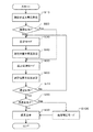
図5は、本実施形態に係る血圧測定装置2の制御機能の要部の具体的な処理内容を説明するフローチャートであり、このフローチャートは、操作入力部30の測定開始ボタンが押されることにより、開始されるようになっている。
FIG. 5 is a flowchart for explaining specific processing contents of the main part of the control function of the blood
この実施形態に係る血圧測定装置2は、電源がONされ、動作がスタートすると、ゼロセッティング、つまり初期リセットを完了する。
The blood
まず、ステップS10では、CPU28は、電磁弁34を開ける信号36を出力して電磁弁34を開け開口部38より大気圧を圧力伝達路20に導入すると同時に、信号36はNOT回路40で電磁弁42を閉じる信号44に変換され電磁弁42を閉じカフ帯12からの圧力伝達路22を遮断する。同時にCPU28は計数部26を高精度モードに設定する。これにより圧力センサー24には圧力伝達路20を介して大気圧が加わり、高精度で圧力センサー24(血圧測定装置2)の高さ位置を計測できる状態になる。例えば、被測定者の操作入力部30の押しボタン押下などの信号に基づきそのときの高精度気圧値である測定位置大気圧値Aを記憶部32に記憶させる。これが測定位置の高さデータとなる。
First, in step S10, the
次に、ステップS20では、CPU28は、前回の血圧測定時、記憶部32に記憶した測定位置大気圧値C(初期値は所定値)と、今回の側定時の測定位置大気圧値Aとの圧力差をΔp(Pa)とすると、上記の高度補正モードと同様に血圧の単位で表し判断する。例えば、規定値を5mmHgとした場合、5mmHg以内の時は(ステップS20:Yes)、ステップS50へ進み、5mmHgを超える時は(ステップS20:No)、ステップS30へ進む。
Next, in step S20, the
次に、ステップS30では、CPU28は、被測定者に血圧測定装置2を心臓の高さと同じ位置に移動することを表示部14等により指示し、例えば、被測定者の操作入力部30の押しボタン押下などの信号に基づきその時の高精度気圧値である心臓位置大気圧値Bを記憶部32に記憶させる。これが心臓の位置の高さデータとなる。
Next, in step S30, the
次に、ステップS40では、CPU28は、被測定者に血圧測定装置2を測定位置に移動することを表示部14等により指示し、例えば、被測定者の操作入力部30の押しボタン押下などの信号に基づきその時の高精度気圧値である測定位置大気圧値Aを記憶部32に記憶させる。これが血圧測定前の測定位置の高さデータとなる。
Next, in step S40, the
次に、ステップS50では、CPU28は電磁弁34を閉じる信号36を出力して電磁弁34を閉じ、同時に信号36はNOT回路40で電磁弁42を開ける信号44に変換され電磁弁42を開ける。これにより圧力センサー24は圧力伝達路20,22を経由し、カフ帯12と同じ圧力範囲となる。同時にCPU28は、計数部26を、血圧計測モードに変更し、カフ帯12の圧力及びその微小な圧力変動を測定できるようにし、血圧測定装置2は血圧計機能としての準備が整うことになる。
Next, in step S50, the
これ以降は通常の血圧計測と同様の動作を行う。CPU28は、駆動信号46を出力して加圧ポンプ16により所定の圧力値まで加圧した後、駆動信号48を出力して排気部18を制御しカフ帯12の圧力を一定の割合で減少させる。この時の微小な圧力変動を検出し特定のアルゴリズムにしたがって一旦仮の最高血圧、最低血圧を算出する。これは減圧時だけでなく、加圧ポンプ16と排気部18とを同時に制御し、カフ帯12の圧力を一定の増加率で増加させる場合も可能である。
Thereafter, the same operation as the normal blood pressure measurement is performed. The
次に、ステップS60では、一旦仮の血圧値が得られた後、CPU28は、ステップS40と同じ設定に戻し、再度大気圧を測定する。例えば、被測定者の操作入力部30の押しボタン押下などの信号に基づきそのときの高精度気圧値である測定位置大気圧値Cを記憶部32に記憶させる。これが血圧測定後の測定位置の高さデータとなる。
Next, in step S60, once a temporary blood pressure value is obtained, the
次に、ステップS70では、CPU28は、ステップS40で記憶した測定位置大気圧値Aと、ステップS60で記憶した測定位置大気圧値Cとの圧力差をΔp(Pa)とすると、上記の高度補正モードと同様に血圧の単位で表し判断する。例えば、規定値を5mmHgとした場合、5mmHg以内の時は(ステップS70:Yes)、ステップS80へ進み、5mmHgを超える時は(ステップS70:No)、ステップS30へ戻り、心臓位置の大気圧測定を行う。
Next, in step S70, the
次に、ステップS80では、CPU28は、ステップS30で記憶した心臓位置大気圧値Bと、ステップS60で記憶した測定位置大気圧値Cとの圧力差をΔp(Pa)とすると、上記の高度補正モードと同様に血圧の単位で表し判断する。例えば、規定値を5mmHgとした場合、5mmHg以内の時は(ステップS80:No)、ステップS90へ進み、5mmHgを超える時は(ステップS80:Yes)、ステップS100へ進む。
Next, in step S80, the
次に、ステップS90では、CPU28は、血圧測定結果として、補正前或いは補正後の血圧値を表示部14に表示し被測定者に知らせ血圧測定を終える。
Next, in step S90, the
次に、ステップS100では、CPU28は、算出した心臓とカフ帯12との高さの気圧の差値から対応する圧力補正値を換算する。次に、血圧測定(決定)結果を補正する。血圧値補正は、圧力補正値を基に決定した血圧値に演算補正することにより行う。ステップS30で記憶した心臓位置大気圧値Bと、ステップS60で記憶した測定位置大気圧値Cとの圧力差をΔp(Pa)とすると、例えば、上記の高度補正モードの式により心臓位置と側定位置の高度差を算出することができる。また、この時の補正に用いられた現在の気圧値は次回の測定でも利用するために記憶部32に保存される。
Next, in step S <b> 100, the
本実施形態では、血圧測定と気圧測定を交互に行うことにより、血圧測定中に腕が移動したかどうか、すなわち、測定値が正しいかどうかの判別にも使用することができる。 In the present embodiment, by alternately performing the blood pressure measurement and the atmospheric pressure measurement, it can be used to determine whether the arm has moved during the blood pressure measurement, that is, whether the measurement value is correct.
2…血圧測定装置 10…本体 12…カフ帯(血圧伝達部) 14…表示部 16…加圧ポンプ(加圧部) 18…排気部 20,22…圧力伝達路 24…圧力センサー(センサー) 26…計数部 28…CPU(制御回路) 30…操作入力部 32…記憶部 34…電磁弁 36…信号 38…開口部 40…NOT回路 42…電磁弁 44…信号 46,48…駆動信号 50…カウンター(L) 52…カウンター(H) 54…ラッチ信号 56…ラッチ回路(L) 58…ラッチ回路(H) 60…リセット信号 62…タイミングクロック発振回路 64…カウンター 66…コンパレーター。
DESCRIPTION OF
Claims (4)
前記センサーで血圧伝達部の内圧変化の測定と、前記センサーで前記血圧伝達部の位置と、該血圧伝達部を装着する被測定者の心臓の位置との大気圧の測定と、を切替える測定切替え部と、
前記センサーで血圧伝達部の内圧変化の測定から前記センサーのセンサー信号を取得し、該センサー信号から得られる前記血圧伝達部の内圧変化に基づいて、血圧値を算出する血圧測定部と、
前記センサーで血圧伝達部の位置と、該血圧伝達部を装着する被測定者の心臓の位置との大気圧を測定するセンサー信号を取得し、該センサー信号から得られる前記血圧伝達部の位置と、該血圧伝達部を装着する被測定者の心臓の位置との大気圧の差に応じた補正値を前記血圧伝達部の内圧変化に基づいて、算出された血圧値に演算する血圧値補正部と、
を含むことを特徴とする血圧測定装置。 A sensor for measuring atmospheric pressure;
Measurement switching for switching the measurement of the internal pressure of the blood pressure transmission unit with the sensor, and the measurement of the atmospheric pressure between the position of the blood pressure transmission unit and the position of the heart of the measurement subject wearing the blood pressure transmission unit with the sensor. And
A blood pressure measurement unit that obtains a sensor signal of the sensor from measurement of an internal pressure change of the blood pressure transmission unit by the sensor, and calculates a blood pressure value based on the internal pressure change of the blood pressure transmission unit obtained from the sensor signal;
A sensor signal for measuring the atmospheric pressure between the position of the blood pressure transmission unit and the position of the heart of the measurement subject wearing the blood pressure transmission unit is acquired by the sensor, and the position of the blood pressure transmission unit obtained from the sensor signal A blood pressure value correction unit that calculates a correction value corresponding to a difference in atmospheric pressure from the position of the heart of the measurement subject wearing the blood pressure transmission unit, based on a change in internal pressure of the blood pressure transmission unit, to a calculated blood pressure value When,
A blood pressure measurement device comprising:
前記センサー信号のサンプリング方法は、前記センサーで前記血圧伝達部の位置と、該血圧伝達部を装着する被測定者の心臓の位置との大気圧の測定より、前記センサーで血圧伝達部の内圧変化の測定の方が高速で、前記センサーで血圧伝達部の内圧変化の測定より、前記センサーで前記血圧伝達部の位置と、該血圧伝達部を装着する被測定者の心臓の位置との大気圧の測定の方が高精度であることを特徴とする血圧測定装置。 The blood pressure measurement device according to claim 1,
The sensor signal sampling method is based on the measurement of the atmospheric pressure between the position of the blood pressure transmission unit by the sensor and the position of the heart of the measurement subject wearing the blood pressure transmission unit. Measurement of the internal pressure of the blood pressure transmission unit by the sensor, and the atmospheric pressure between the position of the blood pressure transmission unit by the sensor and the position of the heart of the measurement subject wearing the blood pressure transmission unit. A blood pressure measurement device characterized in that the measurement of is more accurate.
前記センサーで血圧伝達部の内圧変化の測定と、前記センサーで前記血圧伝達部の位置と、該血圧伝達部を装着する被測定者の心臓の位置との大気圧の測定と、を切替えること、
前記センサーで血圧伝達部の位置と、該血圧伝達部を装着する被測定者の心臓の位置との大気圧を測定するセンサー信号を取得し、該センサー信号から得られる前記血圧伝達部の位置と、該血圧伝達部を装着する被測定者の心臓の位置との大気圧の差に応じた補正値を前記血圧伝達部の内圧変化に基づいて、算出された血圧値に演算すること、
を含むことを特徴とする血圧測定方法。 Obtaining a sensor signal of the sensor from measurement of an internal pressure change of the blood pressure transmission unit by a sensor for measuring an atmospheric pressure, and calculating a blood pressure value based on the internal pressure change of the blood pressure transmission unit obtained from the sensor signal;
Switching the measurement of the internal pressure of the blood pressure transmission unit with the sensor and the measurement of the atmospheric pressure between the position of the blood pressure transmission unit and the position of the heart of the measurement subject wearing the blood pressure transmission unit with the sensor;
A sensor signal for measuring the atmospheric pressure between the position of the blood pressure transmission unit and the position of the heart of the measurement subject wearing the blood pressure transmission unit is acquired by the sensor, and the position of the blood pressure transmission unit obtained from the sensor signal Calculating a correction value according to a difference in atmospheric pressure from the position of the heart of the measurement subject wearing the blood pressure transmission unit based on a change in internal pressure of the blood pressure transmission unit, to a calculated blood pressure value;
A blood pressure measurement method comprising:
前記センサー信号のサンプリング方法は、前記センサーで前記血圧伝達部の位置と、該血圧伝達部を装着する被測定者の心臓の位置との大気圧の測定より、前記センサーで血圧伝達部の内圧変化の測定の方が高速で、前記センサーで血圧伝達部の内圧変化の測定より、前記センサーで前記血圧伝達部の位置と、該血圧伝達部を装着する被測定者の心臓の位置との大気圧の測定の方が高精度であることを特徴とする血圧測定方法。 The blood pressure measurement method according to claim 3,
The sensor signal sampling method is based on the measurement of the atmospheric pressure between the position of the blood pressure transmission unit by the sensor and the position of the heart of the measurement subject wearing the blood pressure transmission unit. Measurement of the internal pressure of the blood pressure transmission unit by the sensor, and the atmospheric pressure between the position of the blood pressure transmission unit by the sensor and the position of the heart of the measurement subject wearing the blood pressure transmission unit. A blood pressure measurement method characterized in that the measurement of is more accurate.
Priority Applications (2)
| Application Number | Priority Date | Filing Date | Title |
|---|---|---|---|
| JP2009261583A JP5471337B2 (en) | 2009-11-17 | 2009-11-17 | Blood pressure measuring device and blood pressure measuring method |
| US12/947,185 US9326692B2 (en) | 2009-11-17 | 2010-11-16 | Blood pressure measurement device and blood pressure measurement method |
Applications Claiming Priority (1)
| Application Number | Priority Date | Filing Date | Title |
|---|---|---|---|
| JP2009261583A JP5471337B2 (en) | 2009-11-17 | 2009-11-17 | Blood pressure measuring device and blood pressure measuring method |
Publications (2)
| Publication Number | Publication Date |
|---|---|
| JP2011104073A true JP2011104073A (en) | 2011-06-02 |
| JP5471337B2 JP5471337B2 (en) | 2014-04-16 |
Family
ID=44011835
Family Applications (1)
| Application Number | Title | Priority Date | Filing Date |
|---|---|---|---|
| JP2009261583A Active JP5471337B2 (en) | 2009-11-17 | 2009-11-17 | Blood pressure measuring device and blood pressure measuring method |
Country Status (2)
| Country | Link |
|---|---|
| US (1) | US9326692B2 (en) |
| JP (1) | JP5471337B2 (en) |
Cited By (4)
| Publication number | Priority date | Publication date | Assignee | Title |
|---|---|---|---|---|
| JP2014068825A (en) * | 2012-09-28 | 2014-04-21 | Omron Healthcare Co Ltd | Electronic sphygmomanometer |
| JP2014180361A (en) * | 2013-03-19 | 2014-09-29 | Yuwa:Kk | Biological data management system |
| JP2014233529A (en) * | 2013-06-04 | 2014-12-15 | 株式会社村田製作所 | Blood pressure manometer |
| WO2017038441A1 (en) * | 2015-09-03 | 2017-03-09 | オムロンヘルスケア株式会社 | Blood pressure measuring device, body characteristic information calculating method, and body characteristic information calculating program |
Families Citing this family (14)
| Publication number | Priority date | Publication date | Assignee | Title |
|---|---|---|---|---|
| CN103190893B (en) * | 2012-01-04 | 2015-05-20 | 深圳市景新浩科技有限公司 | Method and system for calibrating parameters of blood-pressure meter |
| US9710761B2 (en) | 2013-03-15 | 2017-07-18 | Nordic Technology Group, Inc. | Method and apparatus for detection and prediction of events based on changes in behavior |
| US20160120418A1 (en) * | 2013-06-03 | 2016-05-05 | Medieta Oy | Blood pressure measurement device |
| JP6100705B2 (en) * | 2014-01-22 | 2017-03-22 | 日本光電工業株式会社 | Blood pressure measurement system |
| US10129384B2 (en) * | 2014-09-29 | 2018-11-13 | Nordic Technology Group Inc. | Automatic device configuration for event detection |
| JP6548493B2 (en) * | 2015-07-22 | 2019-07-24 | 日本光電工業株式会社 | Blood pressure measuring device |
| JP6631121B2 (en) * | 2015-09-18 | 2020-01-15 | オムロンヘルスケア株式会社 | Blood pressure analysis device, blood pressure measurement device, operation method of blood pressure analysis device, blood pressure analysis program |
| JP6593176B2 (en) * | 2016-01-04 | 2019-10-23 | オムロンヘルスケア株式会社 | Blood pressure correction information generation device, blood pressure measurement device, blood pressure correction information generation method, blood pressure correction information generation program |
| CN112263230B (en) * | 2016-09-22 | 2023-05-09 | 上海潓美医疗科技有限公司 | Dynamic blood pressure monitoring system and method based on radial artery biosensor technology |
| KR102600897B1 (en) * | 2018-04-17 | 2023-11-10 | 삼성전자주식회사 | Electronic apparatus and controlling method thereof |
| CN108926336A (en) * | 2018-06-20 | 2018-12-04 | 苏州大学 | A kind of blood pressure data bearing calibration, device and electronic sphygmomanometer |
| KR102145433B1 (en) * | 2018-08-22 | 2020-08-18 | 주식회사 셀바스헬스케어 | Cardiovascular analyzer |
| WO2020154835A1 (en) * | 2019-01-28 | 2020-08-06 | 华为技术有限公司 | Method and device for measurement compensation |
| CN116602639A (en) * | 2022-02-08 | 2023-08-18 | 华为技术有限公司 | Method for calibrating blood pressure measurement function and electronic equipment |
Citations (4)
| Publication number | Priority date | Publication date | Assignee | Title |
|---|---|---|---|---|
| JPS63283625A (en) * | 1987-05-15 | 1988-11-21 | Matsushita Electric Works Ltd | Electronic hemomanometer |
| WO2002039893A1 (en) * | 2000-11-14 | 2002-05-23 | Omron Corporation | Electronic sphygmomanometer |
| JP2003102692A (en) * | 2001-09-28 | 2003-04-08 | Toshiba Corp | Biological information measuring instrument and system/ method for health management |
| JP2007054648A (en) * | 2000-11-14 | 2007-03-08 | Omron Healthcare Co Ltd | Electronic hemodynamometer |
Family Cites Families (11)
| Publication number | Priority date | Publication date | Assignee | Title |
|---|---|---|---|---|
| US4625277A (en) * | 1984-06-04 | 1986-11-25 | Physio-Control Corporation | Blood pressure measuring device having adaptive cuff deflation rate |
| JPS6266836A (en) | 1985-09-18 | 1987-03-26 | 三洋電機株式会社 | Long-time hemomanometer |
| US4779626A (en) * | 1986-09-09 | 1988-10-25 | Colin Electronics Co., Ltd. | Method and apparatus for compensating for transducer position in blood pressure monitoring system |
| US4779461A (en) * | 1987-02-24 | 1988-10-25 | Lansmont Corporation | Method of and apparatus for measuring and recording the drop height of a container in transit |
| JPH0693882B2 (en) | 1988-08-19 | 1994-11-24 | 株式会社エー・アンド・デイ | Portable blood pressure monitor and processor |
| US5103832A (en) * | 1990-10-11 | 1992-04-14 | Gregmed | Biological pressure transducer zeroing and levelling reference apparatus |
| JP3297971B2 (en) * | 1995-02-16 | 2002-07-02 | オムロン株式会社 | Electronic sphygmomanometer |
| EP1338241B1 (en) * | 1996-04-08 | 2009-07-08 | Seiko Epson Corporation | Exercise workout support device |
| US5957853A (en) * | 1997-10-17 | 1999-09-28 | Vital Evidence, Inc. | Self levelling biological pressure transducer means with input excitation voltage matching amplifier |
| EP1954186A1 (en) * | 2005-11-23 | 2008-08-13 | Koninklijke Philips Electronics N.V. | Enhanced functionality and accuracy for a wrist-based multi-parameter monitor |
| JP5092779B2 (en) | 2008-02-13 | 2012-12-05 | オムロンヘルスケア株式会社 | Blood pressure measurement device |
-
2009
- 2009-11-17 JP JP2009261583A patent/JP5471337B2/en active Active
-
2010
- 2010-11-16 US US12/947,185 patent/US9326692B2/en active Active
Patent Citations (4)
| Publication number | Priority date | Publication date | Assignee | Title |
|---|---|---|---|---|
| JPS63283625A (en) * | 1987-05-15 | 1988-11-21 | Matsushita Electric Works Ltd | Electronic hemomanometer |
| WO2002039893A1 (en) * | 2000-11-14 | 2002-05-23 | Omron Corporation | Electronic sphygmomanometer |
| JP2007054648A (en) * | 2000-11-14 | 2007-03-08 | Omron Healthcare Co Ltd | Electronic hemodynamometer |
| JP2003102692A (en) * | 2001-09-28 | 2003-04-08 | Toshiba Corp | Biological information measuring instrument and system/ method for health management |
Cited By (5)
| Publication number | Priority date | Publication date | Assignee | Title |
|---|---|---|---|---|
| JP2014068825A (en) * | 2012-09-28 | 2014-04-21 | Omron Healthcare Co Ltd | Electronic sphygmomanometer |
| JP2014180361A (en) * | 2013-03-19 | 2014-09-29 | Yuwa:Kk | Biological data management system |
| JP2014233529A (en) * | 2013-06-04 | 2014-12-15 | 株式会社村田製作所 | Blood pressure manometer |
| WO2017038441A1 (en) * | 2015-09-03 | 2017-03-09 | オムロンヘルスケア株式会社 | Blood pressure measuring device, body characteristic information calculating method, and body characteristic information calculating program |
| US11109769B2 (en) | 2015-09-03 | 2021-09-07 | Omron Healthcare Co., Ltd. | Blood pressure measuring apparatus and physical feature information calculating method |
Also Published As
| Publication number | Publication date |
|---|---|
| JP5471337B2 (en) | 2014-04-16 |
| US9326692B2 (en) | 2016-05-03 |
| US20110118613A1 (en) | 2011-05-19 |
Similar Documents
| Publication | Publication Date | Title |
|---|---|---|
| JP5471337B2 (en) | Blood pressure measuring device and blood pressure measuring method | |
| WO2018168797A1 (en) | Blood pressure measurement device, blood pressure measurement method, and program | |
| EP1478269B1 (en) | Method and apparatus for non-invasively measuring hemodynamic parameters using parametrics | |
| JP4754915B2 (en) | Blood pressure monitoring device | |
| RU2719952C2 (en) | Devices for non-invasive monitoring of blood pressure, methods and computer program product for operation with them | |
| KR20100060141A (en) | Portable device for measuring blood pressure and method thereof | |
| US20110257539A1 (en) | Electronic sphygmomanometer and blood pressure measurement method | |
| KR101764527B1 (en) | Portable device for measuring blood pressure and method thereof | |
| JP2009219623A (en) | Blood pressure measurement apparatus, blood pressure derivation program and method for deriving blood pressure | |
| WO2019010416A1 (en) | Self-calibrating systems and methods for blood pressure wave form analysis and diagnostic support | |
| JPWO2015122193A1 (en) | Blood pressure estimation device, blood pressure estimation method, blood pressure measurement device, and blood pressure estimation program | |
| CN114176546A (en) | Blood pressure measuring method and device and electronic equipment | |
| KR20230129505A (en) | Method and system for measuring blood pressure | |
| JP2010194108A (en) | Blood pressure information measuring device and calculation program for arteriosclerosis degree index | |
| WO2021085042A1 (en) | Sphygmomanometer, blood pressure measurement method, and program | |
| JP2008018035A (en) | Apparatus for measuring pulse wave propagation speed, method for calculating pulse wave propagation speed, program and machine readable recording medium having program recorded thereon | |
| TWI584781B (en) | Blood pressure measurement device and method of blood pressure measurement | |
| JP7176711B2 (en) | Blood pressure measuring device | |
| JP2010167181A (en) | Electronic manometer, information processor, measuring management system, measuring management program, and measuring management method | |
| EP4029435B1 (en) | Blood pressure monitoring device and method for adaptive blood pressure monitoring | |
| WO2023016326A1 (en) | Blood pressure calibration method and apparatus, blood pressure measurement system, and electronic device | |
| WO2001049170A1 (en) | Blood pressure measuring method and tonometer | |
| JP2020018558A (en) | Blood pressure measurement device, method and program |
Legal Events
| Date | Code | Title | Description |
|---|---|---|---|
| A621 | Written request for application examination |
Free format text: JAPANESE INTERMEDIATE CODE: A621 Effective date: 20121010 |
|
| A977 | Report on retrieval |
Free format text: JAPANESE INTERMEDIATE CODE: A971007 Effective date: 20131003 |
|
| A131 | Notification of reasons for refusal |
Free format text: JAPANESE INTERMEDIATE CODE: A131 Effective date: 20131008 |
|
| A521 | Written amendment |
Free format text: JAPANESE INTERMEDIATE CODE: A523 Effective date: 20131206 |
|
| TRDD | Decision of grant or rejection written | ||
| A01 | Written decision to grant a patent or to grant a registration (utility model) |
Free format text: JAPANESE INTERMEDIATE CODE: A01 Effective date: 20140107 |
|
| A61 | First payment of annual fees (during grant procedure) |
Free format text: JAPANESE INTERMEDIATE CODE: A61 Effective date: 20140120 |
|
| R150 | Certificate of patent or registration of utility model |
Ref document number: 5471337 Country of ref document: JP Free format text: JAPANESE INTERMEDIATE CODE: R150 Free format text: JAPANESE INTERMEDIATE CODE: R150 |
|
| S531 | Written request for registration of change of domicile |
Free format text: JAPANESE INTERMEDIATE CODE: R313531 |
|
| R350 | Written notification of registration of transfer |
Free format text: JAPANESE INTERMEDIATE CODE: R350 |