JP2011102984A - Navigation device, voice recognition method, and program - Google Patents
Navigation device, voice recognition method, and program Download PDFInfo
- Publication number
- JP2011102984A JP2011102984A JP2010266397A JP2010266397A JP2011102984A JP 2011102984 A JP2011102984 A JP 2011102984A JP 2010266397 A JP2010266397 A JP 2010266397A JP 2010266397 A JP2010266397 A JP 2010266397A JP 2011102984 A JP2011102984 A JP 2011102984A
- Authority
- JP
- Japan
- Prior art keywords
- delay
- microphone
- microphones
- monitor
- unit
- Prior art date
- Legal status (The legal status is an assumption and is not a legal conclusion. Google has not performed a legal analysis and makes no representation as to the accuracy of the status listed.)
- Pending
Links
Images


Abstract
Description
本発明は車載機器に関し、特に音声認識機能を備えたカーナビゲーションシステムに関するものである。 The present invention relates to an in-vehicle device, and more particularly to a car navigation system having a voice recognition function.
GPS(GlobalPositioningSystem:全地球測位システム)を利用したカーナビゲーションシステムが普及している。このカーナビゲーションシステムは、地図情報その他の情報を表示する表示部(一般には、モニタと呼ばれる)と、演算処理装置その他を収容する本体と、カーナビゲーションシステムへの制御情報を入力するためのリモコン等を備えている。最近、リモコンのほかに制御情報を入力する手段として、音声認識機能を有する音声入力装置を備えたカーナビゲーションシステムも実用化されている。この音声入力装置を備えたカーナビゲーションシステムには音声入力用のマイクロフォンが設けられることになる。従来、このマイクロフォンは、例えば、車室内のダッシュボード、ステアリングコラム、サンバイザ、Aピラー部などに取り付けられていた。そして、マイクロフォンは、カーナビゲーションシステムの本体から引き出されたマイクロフォンケーブルに接続されていた。カーナビゲーションシステムの本体は、車室内ではなくトランクルーム内に設置されることが多い。したがって、音声入力装置を備えたカーナビゲーションシステムでは、トランクルームからマイクロフォンケーブルを引き出し、上述のように、車室内のダッシュボード上等にマイクロフォンを取り付けていた。したがって、必要となるマイクロフォンケーブルの長さも7mにも及んでいた。また、マイクロフォンケーブルの配線作業が煩雑であるという問題があった。 Car navigation systems using GPS (Global Positioning System) have become widespread. This car navigation system includes a display unit (generally called a monitor) that displays map information and other information, a main body that houses an arithmetic processing unit and the like, a remote controller for inputting control information to the car navigation system, and the like It has. Recently, a car navigation system including a voice input device having a voice recognition function has been put into practical use as a means for inputting control information in addition to a remote control. A car navigation system equipped with this voice input device is provided with a microphone for voice input. Conventionally, this microphone is attached to, for example, a dashboard, a steering column, a sun visor, an A-pillar portion, etc. in a vehicle interior. The microphone is connected to a microphone cable drawn from the main body of the car navigation system. The main body of a car navigation system is often installed in a trunk room, not in the passenger compartment. Therefore, in a car navigation system equipped with a voice input device, a microphone cable is pulled out from a trunk room, and a microphone is attached on a dashboard or the like in a vehicle cabin as described above. Therefore, the required length of the microphone cable has reached 7 m. In addition, there is a problem that the work of wiring the microphone cable is complicated.
カーナビゲーションシステムの音声入力装置には、音声入力用マイクロフォンの他に、ノイズ信号を入力するためのノイズマイクロフォンを設けることが提案、実用化されている。音声入力用マイクロフォンに入力される信号は音声信号とノイズ信号が混在した信号であり、一方、ノイズマイクロフォンに入力される信号は専らノイズ信号である。したがって、音声入力用マイクロフォンに入力される信号からノイズマイクロフォンに入力される信号を減ずることにより、音声信号のみを抽出することができる。ところが、音声入力用マイクロフォンとノイズマイクロフォンの2つのマイクロフォンを設けることはコストの点で不利である。したがって、1つのマイクロフォンでS/Nが良好となることが望ましい。 It has been proposed and put to practical use in a voice input device of a car navigation system, in addition to a voice input microphone, a noise microphone for inputting a noise signal. The signal input to the audio input microphone is a signal in which an audio signal and a noise signal are mixed, while the signal input to the noise microphone is exclusively a noise signal. Accordingly, only the audio signal can be extracted by subtracting the signal input to the noise microphone from the signal input to the audio input microphone. However, providing two microphones, a voice input microphone and a noise microphone, is disadvantageous in terms of cost. Therefore, it is desirable that the S / N is good with one microphone.
このような問題点を解消し得る音声入力装置が特開平10−11084号公報に開示されている。特開平10−11084号公報の音声入力装置は、遠隔制御を行うためのナビリモコンと、音声認識を用いて制御を行うために音声を入力するマイクロフォンとを有する車載用ナビゲーションシステムの音声入力装置であって、前記ナビリモコン内に前記マイクロフォンを設けることを特徴としている。特開平10−11084号公報に開示された音声入力システムは、カーナビゲーションシステムの制御信号に入力するためのワイヤレスリモコン内にマイクロフォンを設けているため、マイクロフォンケーブルのための配線作業を行う必要がない。しかも、ユーザが音声入力を行う際には、マイクロフォン内蔵のリモコンを口元に近づけて発声することができる。したがって、ノイズの影響を受けにくいという利点もある。 A voice input device capable of solving such problems is disclosed in Japanese Patent Laid-Open No. 10-11084. The voice input device disclosed in Japanese Patent Laid-Open No. 10-11084 is a voice input device for an in-vehicle navigation system having a navigation remote controller for performing remote control and a microphone for inputting voice for performing control using voice recognition. In the navigation remote controller, the microphone is provided. In the voice input system disclosed in Japanese Patent Laid-Open No. 10-11084, a microphone is provided in a wireless remote controller for inputting a control signal of a car navigation system, so that it is not necessary to perform wiring work for a microphone cable. . In addition, when the user performs voice input, the user can speak with the remote controller with a built-in microphone close to the mouth. Therefore, there is an advantage that it is hardly affected by noise.
以上説明したように、ワイヤレスリモコンにマイクロフォンを内蔵する特開平10−11084号公報の提案は従来の問題点を解消することのできる有益なものである。ところが、マイクロフォン内蔵ワイヤレスリモコンに音声入力を行うためには、ユーザが当該ワイヤレスリモコンを持つ必要がある。音声入力を車両走行中に行う場合には、運転操作に支障をきたすおそれがある。したがって、本発明はマイクロフォンのための長いケーブルが不要で、かつマイクロフォンケーブル配線作業が不要かまたは簡便な車載機器、特にカーナビゲーションシステムの提供を課題とする。また本発明は、音声入力時に運転操作に支障をきたすことのない車載機器、特にカーナビゲーションシステムの提供を課題とする。 As described above, the proposal of Japanese Patent Application Laid-Open No. 10-11084 in which a microphone is incorporated in a wireless remote controller is useful for solving the conventional problems. However, in order to input voice to the wireless remote controller with built-in microphone, the user needs to have the wireless remote controller. When voice input is performed while the vehicle is running, there is a risk of impeding driving operations. Accordingly, it is an object of the present invention to provide an in-vehicle device, particularly a car navigation system, which does not require a long cable for a microphone and does not require a microphone cable wiring operation or is simple. It is another object of the present invention to provide an in-vehicle device, particularly a car navigation system, that does not hinder driving operation during voice input.
上記課題を解決するために、本発明のある観点によれば、音声入力用の複数のマイクロフォンと、上記複数のマイクロフォンからの出力信号のそれぞれにディレイを加え、上記ディレイが加えられたそれぞれの信号を加算した音声信号を生成する音声信号生成部と、を有し上記出力信号に加えられるディレイ量を変更することにより指向性軸が変更されるマイクロフォンシステムと、上記複数のマイクロフォンからの出力信号にそれぞれサンプルディレイを加えた信号を加算したサンプル音声信号の出力レベルに基づいて、上記出力信号のそれぞれに対して加えるディレイ量の複数の組合せの中から、一のディレイ量の組合せを選択するディレイ量選択部と、上記ディレイ量選択部により選択されたディレイ量の組合せを用いて生成された上記音声信号を認識する認識部と、上記認識部の認識結果に基づいて当該装置の動作を制御する制御部と、を有する、ナビゲーション装置が提供される。 In order to solve the above-described problem, according to an aspect of the present invention, a plurality of microphones for audio input and a signal added with the delay are added to each of output signals from the plurality of microphones. An audio signal generation unit that generates an audio signal added to the microphone system, the microphone system in which the directivity axis is changed by changing the delay amount added to the output signal, and the output signals from the plurality of microphones A delay amount that selects one delay amount combination from among a plurality of combinations of delay amounts to be added to each of the above output signals, based on the output level of the sample audio signal obtained by adding the signals to which the sample delay has been added. Generated by using a combination of the selection unit and the delay amount selected by the delay amount selection unit. It has a recognition unit for recognizing voice signals, and a control unit for controlling the operation of the device based on the recognition result of the recognition unit, the navigation apparatus is provided.
また、上記ディレイ量選択部は、上記出力レベルが最も高い上記ディレイ量の組合せを選択してもよい。 The delay amount selection unit may select a combination of the delay amounts having the highest output level.
また、上記ディレイ量決定部が決定したディレイ量の組合せを、上記音源である話者と対応づけて記憶する記憶部をさらに有し、上記音声信号生成部は、指定された話者と対応づけて上記記憶部に記憶されたディレイ量の組合せを用いて上記音声信号を生成してもよい。 A storage unit that stores the combination of the delay amounts determined by the delay amount determination unit in association with the speaker as the sound source; and the audio signal generation unit associates with the designated speaker. The audio signal may be generated using a combination of delay amounts stored in the storage unit.
また、上記ディレイ量選択部は、複数の上記ディレイ量の組合せについて上記出力レベルを検出し、上記出力レベルが最も高くなる上記ディレイ量の組合せを選択してもよい。 The delay amount selection unit may detect the output level for a plurality of combinations of the delay amounts, and select the combination of the delay amounts with the highest output level.
また、上記複数のマイクロフォンからの出力信号は、上記でディレイ量選択部を有する音源推定系統と、上記音声信号生成部、上記認識部、および上記制御部を有する出力信号系統とにそれぞれ入力され、上記ディレイ量選択部は、上記出力信号系統において上記制御部が上記認識結果に基づいた制御を行っている期間中、上記ディレイ量の組合せ選択処理を実行してもよい。 The output signals from the plurality of microphones are respectively input to the sound source estimation system having the delay amount selection unit and the output signal system having the audio signal generation unit, the recognition unit, and the control unit. The delay amount selection unit may execute the delay amount combination selection process during a period in which the control unit performs control based on the recognition result in the output signal system.
また、上記複数のマイクロフォンは、等間隔に配置されてもよい。 The plurality of microphones may be arranged at equal intervals.
また、上記課題を解決するために、本発明の別の観点によれば、複数のマイクロフォンにより音声を取得するステップと、上記複数のマイクロフォンからの出力信号にそれぞれサンプルディレイを加えるステップと、上記サンプルディレイが加えられた信号を加算したサンプル音声信号を生成するステップと、上記サンプル音声信号の出力レベルを検出するステップと、上記出力レベルに基づいて、上記出力信号の夫々に対して加えるディレイ量の組合せを選択するステップと、選択された上記ディレイ量の組合せに基づいて、上記複数のマイクロフォンからの出力信号のそれぞれにディレイを加えるステップと、上記ディレイが加えられたそれぞれの信号を加算することにより、音声信号を生成するステップと、上記音声信号を認識するステップと、上記認識の結果に基づいて当該装置の動作を制御するステップと、を含む、音声認識方法が提供される。 In order to solve the above-described problem, according to another aspect of the present invention, a step of acquiring sound by a plurality of microphones, a step of adding a sample delay to output signals from the plurality of microphones, and the sample A step of generating a sample audio signal obtained by adding the signals to which the delay has been added, a step of detecting an output level of the sample audio signal, and a delay amount to be added to each of the output signals based on the output level A step of selecting a combination, a step of adding a delay to each of the output signals from the plurality of microphones based on the selected combination of the delay amounts, and adding each signal to which the delay has been added A step of generating an audio signal and a step of recognizing the audio signal. And-up, based on the result of the recognition including the steps of controlling the operation of the apparatus, the speech recognition method is provided.
また、上記課題を解決するために、本発明の別の観点によれば、コンピュータを、音声入力用の複数のマイクロフォンと、上記複数のマイクロフォンからの出力信号のそれぞれにディレイを加え、上記ディレイが加えられたそれぞれの信号を加算した音声信号を生成する音声信号生成部と、を有し上記出力信号に加えられるディレイ量を変更することにより指向性軸が変更されるマイクロフォンシステムと、上記複数のマイクロフォンからの出力信号にそれぞれサンプルディレイを加えた信号を加算したサンプル音声信号の出力レベルに基づいて、上記出力信号のそれぞれに対して加えるディレイ量の複数の組合せの中から、一のディレイ量の組合せを選択するディレイ量選択部と、上記ディレイ量選択部により選択されたディレイ量の組合せを用いて生成された上記音声信号を認識する認識部と、上記認識部の認識結果に基づいて当該装置の動作を制御する制御部とを有する、ナビゲーション装置として機能させるためのプログラムが提供される。 In order to solve the above problems, according to another aspect of the present invention, a computer adds a delay to each of a plurality of microphones for voice input and an output signal from the plurality of microphones. An audio signal generation unit that generates an audio signal obtained by adding the added signals, and a microphone system in which a directivity axis is changed by changing a delay amount added to the output signal; Based on the output level of the sampled audio signal obtained by adding the signal obtained by adding the sample delay to the output signal from the microphone, one delay amount is selected from among a plurality of combinations of delay amounts added to each of the output signals. A combination of a delay amount selection unit for selecting a combination and a delay amount selected by the delay amount selection unit. A program for functioning as a navigation device is provided, which includes a recognition unit for recognizing the voice signal generated by using the control unit and a control unit for controlling the operation of the device based on the recognition result of the recognition unit. .
本発明者は、マイクロフォンケーブルの引き出しの対象としてモニタを利用することに着目した。カーナビゲーションシステムにおいて、モニタは、通常、ダッシュボード上に取り付けられている。したがって、モニタからマイクロフォンケーブルを引き出し、例えば、ダッシュボード上にマイクロフォンを取り付けたとしても、マイクロフォンケーブルは従来に比べて短くてすみ、かつ配線作業も極めて簡便である。しかも、モニタから引き出されたマイクロフォンは、ダッシュボードのほか、ステアリングコラム、サンバイザ、Aピラー部といった従来と同様の個所に取り付けて使用することができるから、ユーザがマイクロフォンを手に持つ必要がない。また、マイクロフォンケーブル自体を無くすことも可能である。つまり、マイクロフォンをモニタを構成する筐体と一体化することによっても、前記課題を解決できることを知見した。この場合、マイクロフォンケーブルが存在しないことになるので、配線作業は全く不要となる。しかも、マイクロフォンケーブルが車室内に露出することがないため、配線が露出することによる見栄えの劣化という心配もなくなる。 The inventor of the present invention paid attention to the use of a monitor as a target for drawing out a microphone cable. In a car navigation system, a monitor is usually mounted on a dashboard. Therefore, even if the microphone cable is pulled out from the monitor and the microphone is mounted on the dashboard, for example, the microphone cable can be shorter than the conventional one and the wiring work is very simple. In addition to the dashboard, the microphone pulled out from the monitor can be mounted and used at the same location as the steering column, sun visor, A-pillar portion, and the user does not need to hold the microphone. It is also possible to eliminate the microphone cable itself. That is, it has been found that the above-mentioned problem can be solved by integrating the microphone with the housing constituting the monitor. In this case, since no microphone cable is present, no wiring work is required. In addition, since the microphone cable is not exposed in the vehicle interior, there is no need to worry about deterioration of appearance due to the exposed wiring.
本発明は以上のような利点を供えた車載機器であって、音声認識を用いて制御することのできる車載機器であって、地図情報その他の情報を表示するためのモニタと、音声入力用のマイクロフォンと、を備え、前記マイクロフォンが前記モニタに接続されることを特徴とする車載機器である。本発明の車載機器において、音声入力用のマイクロフォン(以下、単にマイクロフォンという)を前記モニタに接続する形態としては、マイクロフォン用のケーブルを介して前記モニタに接続する形態と、ケーブルを介さずにマイクロフォンを直接前記モニタに接続する形態がある。ケーブルを介して前記モニタに接続する形態によれば、トランクルームから車室内前部まで配線作業をしていた従来に比べて配線作業が著しく軽減される。また、ケーブルの長さも従来に比べて短くて済む。マイクロフォンを直接モニタに接続する形態によれば、配線作業自体が不要となる。しかも、ケーブルが不要となるため、従来のようにケーブルが車室内に露出することがないため、見栄えが悪い、といったユーザからの苦情を解決することができる。ケーブルを介してマイクロフォンをモニタに取り付けた場合、マイクロフォンを設置する位置は任意である。つまり、従来のように、ダッシュボード、ステアリングコラム、サンバイザ、Aピラーといった個所にマイクロフォンを設置することができる。マイクロフォンを直接前記モニタに接続する形態としては、以下の2つの形態がある。一般にモニタは、液晶表示素子等の表示部、その他の部分を保持する筐体を備えているが、その筐体外側にマイクロフォンを取り付ける形態と、筐体内部にマイクロフォンを取り付ける(内蔵する)形態である。いずれの場合であっても、マイクロフォンはモニタに設置されることになる。 The present invention is an in-vehicle device that has the advantages as described above, and can be controlled using voice recognition, and includes a monitor for displaying map information and other information, and a voice input device. An in-vehicle device, wherein the microphone is connected to the monitor. In the in-vehicle device according to the present invention, a voice input microphone (hereinafter simply referred to as a microphone) is connected to the monitor as a form connected to the monitor via a microphone cable, or a microphone without a cable. Is directly connected to the monitor. According to the form of connecting to the monitor via a cable, the wiring work is significantly reduced as compared with the conventional case where the wiring work is performed from the trunk room to the front part of the vehicle interior. Also, the length of the cable can be shorter than the conventional one. According to the embodiment in which the microphone is directly connected to the monitor, the wiring work itself becomes unnecessary. In addition, since the cable is not necessary, the cable is not exposed to the vehicle interior as in the conventional case, and it is possible to solve a complaint from the user that the appearance is poor. When the microphone is attached to the monitor via a cable, the position where the microphone is installed is arbitrary. In other words, the microphone can be installed in places such as the dashboard, the steering column, the sun visor, and the A-pillar as in the past. There are the following two forms for directly connecting the microphone to the monitor. In general, a monitor includes a housing for holding a display unit such as a liquid crystal display element and other parts. The monitor is attached to the outside of the housing, and the microphone is attached (built in) to the inside of the housing. is there. In either case, the microphone will be installed on the monitor.
モニタに接続されるマイクロフォンの数は単数に限らず、複数とすることもできる。また、マイクロフォンはモニタに対して着脱自在とすることもできる。つまり、マイクロフォンのケーブルまたはマイクロフォン自体が、前記モニタに対して着脱自在に接続されるようにすることも本発明の範囲内である。マイクロフォンを直接モニタに接続する場合には、マイクロフォンをモニタに対して固定とすることもできるが、その向きを変更可能とすることもできる。マイクロフォンの指向性軸を話者に対して最適な向きとすることが望ましいからである。マイクロフォンの向きを変更する手段としては、ユーザによる手動の他、モータ等の駆動源を用いることができる。 The number of microphones connected to the monitor is not limited to one, but may be plural. Further, the microphone can be detachable from the monitor. That is, it is also within the scope of the present invention that the microphone cable or the microphone itself is detachably connected to the monitor. When the microphone is directly connected to the monitor, the microphone can be fixed with respect to the monitor, but the direction can be changed. This is because it is desirable to set the microphone directivity axis to an optimum direction with respect to the speaker. As means for changing the direction of the microphone, a driving source such as a motor can be used in addition to manual operation by the user.
本発明の車載機器の典型的な適用例はカーナビゲーションシステムである。したがって、本発明では入力された音声を認識するための認識部と、前記認識部で認識された結果を表示するためのモニタと、前記モニタに一体的に接続され、かつ前記音声を入力するためのマイクロフォンと、を備えたことを特徴とするカーナビゲーションシステムが提供される。また、カーオーディオにも適用することができるが、車載機器であれば用途は問わない。また、車室内において、マイクロフォンには音声認識のための音声の他に、エンジン音、その他のノイズが入力される。本発明のカーナビゲーションシステムにおいては、ノイズを抑制するためのノイズ抑制手段を設けることができる。ノイズ抑制手段としては、公知のノイズ抑制手段を広く適用することができるが、本発明において特徴的なノイズ抑制手段は、マイクロフォンをモニタに直接接続した場合に機能する。つまり、モニタ全体の回折効果によりマイクロフォンの感度が向上し、ノイズが抑制される。したがってこの場合には、モニタがノイズ抑制手段を構成することになる。ノイズを抑制する手法として、ノイズ集音用のマイクロフォンを音声入力用のマイクロフォンとは別途設けることが従来より行われている。本発明では、モニタの表裏いずれか一方の面に音声入力用マイクロフォンを設置し、またモニタの他方の面にノイズ入力用マイクロフォンを設置することができる。つまり本発明では、地図情報その他の情報を表示するためのモニタ本体と、前記モニタ本体の表裏いずれか一方の面に設置した音声入力用マイクロフォンと、前記モニタ本体の他方の面に設置したノイズ入力用マイクロフォンと、を備えたことを特徴とするモニタ装置が提供される。ノイズ入力用マイクロフォンは前述のノイズ抑制手段に該当するが、音声入力用マイクロフォンが設置されたモニタ本体の面の裏面に設置する点に特徴を有する。その利点については、後述する発明の実施の形態において説明する。 A typical application example of the vehicle-mounted device of the present invention is a car navigation system. Therefore, in the present invention, a recognition unit for recognizing the input voice, a monitor for displaying a result recognized by the recognition unit, and a single unit connected to the monitor for inputting the sound. And a car navigation system characterized by comprising the above microphone. Moreover, although it can apply also to a car audio, if it is in-vehicle equipment, a use will not ask | require. In the vehicle interior, engine sound and other noises are input to the microphone in addition to the voice for voice recognition. In the car navigation system of the present invention, noise suppression means for suppressing noise can be provided. As the noise suppression means, known noise suppression means can be widely applied, but the characteristic noise suppression means in the present invention functions when a microphone is directly connected to a monitor. That is, the sensitivity of the microphone is improved by the diffraction effect of the entire monitor, and noise is suppressed. Therefore, in this case, the monitor constitutes noise suppression means. As a technique for suppressing noise, it has been conventionally practiced to provide a noise collecting microphone separately from a voice input microphone. In the present invention, an audio input microphone can be installed on either the front or back side of the monitor, and a noise input microphone can be installed on the other side of the monitor. That is, in the present invention, a monitor main body for displaying map information and other information, a voice input microphone installed on one of the front and back surfaces of the monitor main body, and a noise input installed on the other surface of the monitor main body And a microphone for monitoring. The noise input microphone corresponds to the noise suppression means described above, but is characterized in that it is installed on the back surface of the monitor main body on which the voice input microphone is installed. The advantages will be described in the embodiments of the invention described later.
以上説明したように、本発明の車載機器によれば、マイクロフォンをモニタに接続したので、マイクロフォンのための長いケーブルが不要で、かつマイクロフォンフォンケーブル配線作業が不要かまたは簡便となる。 As described above, according to the in-vehicle device of the present invention, since the microphone is connected to the monitor, a long cable for the microphone is unnecessary, and the microphone cable wiring work is unnecessary or simple.
<第1実施形態>
以下、添付図面に示す実施の形態に基づいてこの発明を詳細に説明する。図1は第1実施形態におけるカーナビゲーションシステムの全体的なシステム構成を説明するための図である。この図において、符号1はナビゲーション装置の全体を司る演算処理部、2は自らの位置を計測する測位部、3はカーナビゲーションシステムの操作手段としてのリモートコントローラ、4はリモートコントローラ3からの操作情報を受信する受信部、5は入力された音声を認識処理する認識部、6は地図情報その他の情報を表示するためのモニタである。
<First Embodiment>
Hereinafter, the present invention will be described in detail based on embodiments shown in the accompanying drawings. FIG. 1 is a diagram for explaining the overall system configuration of the car navigation system according to the first embodiment. In this figure,
ここで、演算処理部1は、その全体を制御するCPU7と、所定のプログラムが格納されたROM8と、各種データを記憶するRAM9と、前記測位部2、受信部4、認識部5、モニタ6等との間で入出力を行うI/O回路部10とを備えている。測位部2は、GPS(GlobalPositioningSystem:全地球測位システム)により測位を行うもので、高度約2万km上の複数(通常4つ以上)のGPS衛星から発信された1575.42MHzの信号(電波)を図示しない受信アンテナで受信し、この信号に基づき測位計算を行い、現在位置を示す測位データを演算処理部1に転送する。また、このカーナビゲーションシステムの各種操作は、リモートコントローラ3により行うことができる。このリモートコントローラ3は、例えば操作メニューをモニタ6に表示させたり、モニタ6への電子地図の表示範囲を変更したり、モニタ6に表示された各種操作メニュー等においてカーソルを移動させたり、することができる。そして、このリモートコントローラ3による操作情報に基づく信号はワイヤレスで送信され、これが受信部4において受信された後、演算処理部1に伝達されてその操作内容が実行される。
Here, the
モニタ6には音声入力用のマイクロフォン40が接続してある。このマイクロフォン40で入力された音声によっても、リモートコントローラ3と同様にカーナビゲーションシステムの各種操作を制御することができるし、その結果がモニタ6に表示される。例えば、行き先を音声で指示することにより、その行き先を含む地図情報をモニタ6に表示させることができる。マイクロフォン40に入力された音声は、認識部5で認識処理がなされる。認識部5は図2に示すように、CPU51と、所定のプログラムが格納されたROM52と、各種データを記憶するRAM53とから構成される。認識部5では図3に示すように認識処理が実行される。すなわち、入力された音声信号をアナログ値からデジタル値に変換する。変換された音声信号に対してノイズ抑制処理を施した後に、音響分析を行う。ノイズ抑制処理は公知の手法を適用することができる。音響分析においては、音声の特徴量を抽出する。その後、この抽出された特徴量と標準パターンとを比較することにより音声認識がなされる。認識された結果は、モニタ6に表示される。さらに、このカーナビゲーションシステムには、図1に示したように、地図情報その他の情報を記憶した記憶媒体11が備えられている。
A
図4は、モニタ6の正面図を示す。モニタ6は、地図情報その他を表示するための表示部61と、表示部61その他を収容するモニタ筐体62とから構成される。モニタ6のモニタ筐体62からは、マイクロフォン40のマイクロフォンケーブル41が引き出されている。本実施の形態においてマイクロフォンケーブル41はモニタ筐体62に固着させているが、着脱自在とすることもできる。つまり、モニタ筐体62にコネクタを内蔵し、そのコネクタに対してマイクロフォンケーブル41を着脱可能とする。モニタ6はコラム63を介してダッシュボード、コンソールボックス等の車室内前部に取り付けられる。したがって、マイクロフォン40を、従来のように、サンバイザ、あるいはダッシュボード上に取り付けたとすると、マイクロフォンケーブル41の長さは1〜2m程度あれば十分に足りる。なお、マイクロフォン40を取り付ける位置を限定するものではなく、サンバイザ、ダッシュボードの他、車室内の任意の位置に取り付けることができる。もっとも、マイクロフォン40に対する話者は、運転手または助手席に座っている者であろうから、車室内前部のいずれかの位置ということになろう。
FIG. 4 shows a front view of the monitor 6. The monitor 6 includes a
また、本実施の形態によれば、従来のようにトランクルームからマイクロフォンケーブルを車室内前部まで配線するのに比べて、モニタ6が車室内前部に配置されているため、マイクロフォンケーブル41の配線作業は簡単である。本実施の形態において、マイクロフォン40およびマイクロフォンケーブル41は、従来公知のものを適用することができる。たとえば、マイクロフォン40としては、単一指向性マイクロフォンおよび無指向性マイクロフォンがあるが、いずれでも使用することができる。ただし、単一指向性マイクロフォンの方が、ノイズの集音の可能性が低くなることから望ましい。また、本実施の形態ではマイクロフォン40は単数としているが、複数取り付けてもよい。
Further, according to the present embodiment, the monitor 6 is disposed in the front part of the vehicle interior as compared with the conventional case where the microphone cable is wired from the trunk room to the front part of the vehicle interior. The work is simple. In the present embodiment, conventionally known
<第2実施形態>
本発明にかかる第2実施形態を図5および図6に基づき説明する。なお、第2実施形態にかかるカーナビゲーションシステムの基本構成は、第1実施形態と同様であるので、ここでは相違点を中心に説明する。図5に示すように、第2実施形態にかかるモニタ160は、地図情報その他を表示するための表示部161と、表示部161その他を収容するモニタ筐体162とから構成される。第2実施形態が第1実施形態と相違する点は、第1実施形態がマイクロフォン40とモニタ筐体62とがマイクロフォンケーブル41を介して接続されているのに対して、第2実施形態はマイクロフォン140がモニタ筐体162に直接接続されている点である。また、モニタ筐体162にはマイクロフォン140と接続されるコネクタが内蔵されており、図6に示すようにマイクロフォン140はモニタ筐体162に着脱自在となっている。
Second Embodiment
A second embodiment according to the present invention will be described with reference to FIGS. Note that the basic configuration of the car navigation system according to the second embodiment is the same as that of the first embodiment, and therefore, differences will be mainly described here. As shown in FIG. 5, the
以上の第2実施形態によれば、マイクロフォン140がモニタ筐体162に直接接続されているので、マイクロフォンケーブルの配線作業が全く不要となる。また、マイクロフォンケーブルが車室内に露出することがない。車室内にマイクロフォンケーブルが露出すると見栄えが悪いと嫌うユーザもいるが、この第2実施形態は、このようなユーザの要望に応えることができる。また、この第2実施形態のようにモニタ160にマイクロフォン140を直接接続、つまり一体的に取り付けることにより、ノイズ抑制効果が期待できる。つまり、モニタ160全体の回折効果によりマイクロフォン140の感度が向上するためである。この回折効果による感度向上は、人間が小さい音を聞くときに耳の後ろに手のひらをあてることにより経験することができる。
According to the second embodiment described above, since the
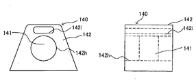
本第2実施形態において、マイクロフォン140は、図7に示すように、マイクロフォン本体141とマイクロフォン筐体142とから構成される。マイクロフォン本体141は単一指向性のマイクロフォンから構成されているが、この指向特性をマイクロフォン筐体142と組み合わせることにより制御し、音声を増幅しノイズを抑制している。単一指向性のマイクロフォン本体141は、正面の音響端子と背面の音響端子間の距離、つまり音響2端子間距離、を長く取ることにより指向性を向上することができる。図7はマイクロフォン140の正面図(左側)および側面図(右側)を示しているが、マイクロフォン筐体142は、貫通孔142hを有する断面がかまくら型をなしていることがわかる。マイクロフォン本体141は、この貫通孔142hの貫通方向の中間部に配置されている。マイクロフォン本体141単体の音響2端子間距離がd1であるのに対して、マイクロフォン筐体142と組み合わせることにより、マイクロフォン140としての音響2端子間距離d2を、マイクロフォン本体141単体の音響2端子間距離d1より大きくすることができる。市販されているマイクロフォン本体141は図7に示すように単純な円柱形であることが多いが、本実施の形態によれば、市販のマイクロフォン本体141を用い、かつモニタ160にマイクロフォン本体141を取り付けるためのマイクロフォン筐体142と組み合わせることにより、音響2端子間距離を大きくすることができるという利点がある。本実施の形態ではマイクロフォン筐体142をかまくら型としたが、本発明はこれに限定されない。マイクロフォン本体140をモニタ160に取り付ける機能と、音響2端子間距離を大きくすることができる機能を備えていれば、如何なる形態であっても本発明にとって有効である。図8にマイクロフォン140の他の構成例を示す。図8のマイクロフォン140は、図7に示したマイクロフォン140と基本的には同様の構成からなるが、マイクロフォン筐体142の上部に貫通孔142iを形成している。この貫通孔142iを空気が流通することにより、マイクロフォン140が日射などにより高熱になることを防止することができる。
In the second embodiment, the
<第3実施形態>
本発明にかかる第3実施形態を図9および図10に基づき説明する。なお、第3実施形態にかかるカーナビゲーションシステムの基本構成は、第1〜第2実施形態と同様であるので、ここでは相違点を中心に説明する。また、図9は第3実施形態にかかるモニタ260の正面図であり、図10は同背面図である。図9に示すように、第3実施形態にかかるモニタ260は、地図情報その他を表示するための表示部261と、表示部261その他を収容するモニタ筐体262とから構成される。第3実施形態が第2実施形態と相違する点は、第2実施形態がマイクロフォン140がモニタ筐体162の外部に取り付けられているのに対して、第3実施形態はマイクロフォン240がモニタ筐体262内部に埋め込まれている点である。
<Third Embodiment>
A third embodiment according to the present invention will be described with reference to FIGS. Note that the basic configuration of the car navigation system according to the third embodiment is the same as that of the first and second embodiments, and therefore, differences will be mainly described here. FIG. 9 is a front view of a
以上の第3実施形態によれば、マイクロフォン240がモニタ筐体262に直接接続されている。したがって、第2実施形態と同様に、マイクロフォンケーブルの配線作業が全く不要となる、マイクロフォンケーブルが車室内に露出することがない、といった効果を有する。しかも、マイクロフォン240が、モニタ筐体262内部に埋め込まれているので、第2実施形態のようにマイクロフォン140がモニタ160の外部に突出することなくすっきりとした感じとなる。また、第3実施形態によっても、第2実施形態と同様に、マイクロフォン240をモニタ260に取り付けているので、モニタ260全体の回折効果によりマイクロフォン240の感度を向上することができる。
According to the third embodiment described above, the
第3実施形態では、図10に示すように、モニタ260の背面側に、ノイズを集音するためのノイズマイクロフォン241をモニタ筐体262に内蔵させている。図9に示したマイクロフォン240は、音声のみならず雑音をも集音する。一方、ノイズマイクロフォン241は雑音を集音する。したがって、マイクロフォン240による「音声信号+雑音信号」からノイズマイクロフォン241による「雑音信号」を減ずれば、音声信号のみを抽出することができる。このように一方のマイクロフォンを「音声信号+雑音信号」用に、他方のマイクロフォンを「雑音信号」用に用い、「音声信号」のみを抽出する技術は既に知られている。しかし、第3実施形態のように、モニタ260の表裏面にそれぞれ「音声信号+雑音信号」用のマイクロフォン240および「雑音信号」用のノイズマイクロフォン241を配置する構成は新規である。
In the third embodiment, as shown in FIG. 10, a
マイクロフォン240とノイズマイクロフォン241との距離が離れていると、マイクロフォン240で集められる雑音信号とノイズマイクロフォン241で集められる雑音信号とが相違するため、「音声信号+雑音信号」から「雑音信号」を減ずるという処理が現実的でなくなる。したがって、マイクロフォン240とノイズマイクロフォン241とは近接した位置に配置されることが望ましい。ところが、ノイズマイクロフォン241は、雑音信号がほしい信号であるから、話者の音声を集めにくい位置に配置されるべきである。つまり、この点を考慮すると、マイクロフォン240とノイズマイクロフォン241とは、あまり近い位置に配置することは望ましくない。しかるに、第3実施形態のように、モニタ260の背面側にノイズマイクロフォン241を配置すれば、話者からの音声はモニタ260により遮られる。つまり、ノイズマイクロフォン241は、話者の音声を集めにくい位置に配置されているということができる。しかも、ノイズマイクロフォン241は、マイクロフォン240と近接した位置に配置すべきであるという要求をも満足することができる。したがって、「音声信号+雑音信号」から「雑音信号」を減ずるという処理が、有効なものとなる。
When the distance between the
第3実施形態ではマイクロフォン240およびノイズマイクロフォン241を各々2個ずつ設けた例を示したが、本発明はこれに限定されず、各々1個ずつ設けてもよいし、各々3個以上設けてもよい。また、マイクロフォン240およびノイズマイクロフォン241を配置する位置についても、第3実施形態ではモニタ260の上部両端としたが、これに限定されず、マイクロフォン240およびノイズマイクロフォン241の個数に応じて適宜定めることができる。ノイズ抑制は、以上の他に、例えば図11に示すような電気的な仕組みによっても行うこともできる。図11において、Mがマイクロフォン、Aがアンプ、τが1サンプルのディレイを示しているが、このような公知の電気的なノイズ抑制手段を設けることができる。
In the third embodiment, an example in which two
<第4実施形態>
本発明にかかる第4実施形態を図12および図13に基づき説明する。なお、第4実施形態にかかるカーナビゲーションシステムの基本構成は、第1〜第3実施形態と同様であるので、ここでは相違点を中心に説明する。また、図12は第4実施形態にかかるモニタ360の正面図であり、図13は平面図である。図12に示すように、第4実施形態にかかるモニタ360は、地図情報その他を表示するための表示部361と、表示部361その他を収容するモニタ筐体362とから構成される。第4実施形態は、第2実施形態と同様に、モニタ筐体362にマイクロフォン340が直接接続されている。第2実施形態では、モニタ筐体162に取り付けられたマイクロフォン140は着脱自在ではあったものの、その向きを変えることはできなかった。ところが、第4実施形態では、マイクロフォン340の向きを変えることが可能に構成されている。つまり、図13に示すように、マイクロフォン340は、モニタ360に対して回動可能に取り付けられている。したがって、話者、つまり音源に対してマイクロフォン340の指向性軸を向けることができる。
<Fourth embodiment>
A fourth embodiment according to the present invention will be described with reference to FIGS. Since the basic configuration of the car navigation system according to the fourth embodiment is the same as that of the first to third embodiments, the differences will be mainly described here. FIG. 12 is a front view of a
マイクロフォン340の回動は、手動で行うこととしてもよいし、モータ等の駆動源を用いて行うようにしてもよい。第4実施形態のように複数のマイクロフォン340を設ける場合には、リンク機構その他を利用して複数のマイクロフォン340を同時に回動するようにすることができる。また、第4実施形態では、水平方向にマイクロフォン340の向きを変える例を示したが、鉛直方向に向きを変えることもできる。また、各話者に適したマイクロフォン340の向きを予め登録(プリセット)しておき、その話者がドライバとなった際に、プリセットしておいた向きにマイクロフォン340が向くようにすることもできる。例えば、第4実施形態によるナビゲーション装置を搭載した自動車を家族で使用する場合には、その家族で当該自動車を運転する者毎にマイクロフォン340の向きをプリセットしておく。そして、自分が運転する場合には、プリセットしておいたマイクロフォン340の向きを読み出し、その向きにマイクロフォン340の向きをセットさせる。
The
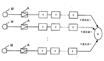
マイクロフォン340の向きのプリセットは、音源推定手段を用いることにより実現することができる。図14に音源推定手段の1例を示すが、図11に示したノイズ抑制手段を利用したものである。図11に示したノイズ抑制手段は、τ(1サンプルディレイ)が各マイクロフォンMに付加されているが、そのディレイ量をソフト的に増減させることでマイクロフォンシステムとしての指向性軸を変えることができるというものである。例えば、図14に示すように4つのマイクロフォンM1〜M4が等間隔に配置されていたとする。出力信号系統とは別に音源推定系を設け、その中で逐次ディレイ量変更を行う。はじめに、マイクロフォンM1の出力には6サンプルディレイ、マイクロフォンM2には4サンプルディレイおよびマイクロフォンM3には2サンプルディレイを加算し、マイクロフォンM4にはディレイ無し、とし、それらの出力を加算して音声出力レベルを検出する。次に、マイクロフォンM1の出力にはディレイ無し、マイクロフォンM2には2サンプルディレイおよびマイクロフォンM3には4サンプルディレイおよびマイクロフォンM4には6サンプルディレイを加算、とし、それらの出力を加算して音声出力レベルを検出する。さらに、全てのマイクロフォンM1〜M4にディレイをかけない場合の音声出力レベルを検出する。これら3種類の音声出力レベルの中で、最もレベルの高いものを選び、そのときのディレイのかけかたを出力信号系統にコピーして音源推定処理を行う。マイクロフォン340のプリセットについては、上記の音源推定手段の他に、公知の如何なる手段を採用してもよい。
The preset of the direction of the
<第5実施形態>
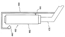
本発明にかかる第5実施形態を図15および図16に基づき説明する。なお、第5実施形態にかかるナビゲーションシステムの基本構成は第1実施形態と同様であり、マイクロフォン440はマイクロフォンケーブル441を介してモニタ460に接続された構成となっている。図15および図16に示すように、第5実施形態にかかるモニタ460は地図情報その他を表示するための表示部461と、表示部461その他を収容するモニタ筐体462とから構成される。モニタ460は、コラム470を介して車室内前部の任意の位置に取り付けられる。一般的には、ダッシュボードの車体幅方向の中央部に取り付ける。コラム470からマイクロフォン440を固定するためのL字状かつ中空のアーム480が延設されている。アーム480の先端部にマイクロフォン440が取り付けられている。マイクロフォン440は、モニタ460の表面に近接配置されている。マイクロフォン440は、マイクロフォンケーブル441を介してモニタ460に接続されている。マイクロフォンケーブル441は、モニタ460の背面から引き出され、アーム480の中空部に配線されてマイクロフォン440に接続される。
<Fifth Embodiment>
A fifth embodiment according to the present invention will be described with reference to FIGS. 15 and 16. The basic configuration of the navigation system according to the fifth embodiment is the same as that of the first embodiment, and the
第2(第3,第4)実施形態のように、マイクロフォン140(240,340)をモニタ160(260,360)に直接接続した場合には、モニタ160(260,360)全体の回折効果によりマイクロフォン140(240,340)の感度を向上することができた。第5実施形態の場合には、マイクロフォン440をマイクロフォンケーブル441を介してモニタ460に接続されているが、アーム480を用いてマイクロフォン440をモニタ460の表面に近接配置している。したがって、モニタ460全体の回折効果により、マイクロフォン440の感度を向上することができる。
When the microphone 140 (240, 340) is directly connected to the monitor 160 (260, 360) as in the second (third, fourth) embodiment, the diffraction effect of the entire monitor 160 (260, 360) is caused. The sensitivity of the microphone 140 (240, 340) could be improved. In the case of the fifth embodiment, the
1…演算処理部、3…リモートコントローラ、5…認識部、6,160,260,360,460…モニタ、11…記憶媒体、40,140,240,340,440…マイクロフォン、41,441…マイクロフォンケーブル、61,161,261,361,461…表示部、62,162,262,362,462…モニタ筐体
DESCRIPTION OF
Claims (8)
前記複数のマイクロフォンからの出力信号にそれぞれサンプルディレイを加えた信号を加算したサンプル音声信号の出力レベルに基づいて、前記出力信号のそれぞれに対して加えるディレイ量の複数の組合せの中から、一のディレイ量の組合せを選択するディレイ量選択部と、
前記ディレイ量選択部により選択されたディレイ量の組合せを用いて生成された前記音声信号を認識する認識部と、
前記認識部の認識結果に基づいて当該装置の動作を制御する制御部と、
を備える、ナビゲーション装置。 A plurality of microphones for voice input; and an audio signal generation unit that adds a delay to each of output signals from the plurality of microphones and generates an audio signal obtained by adding the signals to which the delay has been added. A microphone system in which the directivity axis is changed by changing the amount of delay applied to the output signal;
Based on the output level of the sample audio signal obtained by adding the signal obtained by adding the sample delay to the output signal from the plurality of microphones, one of the combinations of the delay amounts to be added to each of the output signals is A delay amount selection section for selecting a combination of delay amounts;
A recognition unit for recognizing the audio signal generated using the combination of delay amounts selected by the delay amount selection unit;
A control unit for controlling the operation of the apparatus based on the recognition result of the recognition unit;
A navigation device comprising:
をさらに備え、
前記音声信号生成部は、指定された話者と対応づけて前記記憶部に記憶されたディレイ量の組合せを用いて前記音声信号を生成する、請求項1または2に記載のナビゲーション装置。 A storage unit for storing a combination of delay amounts determined by the delay amount determination unit in association with a speaker as the sound source;
Further comprising
The navigation device according to claim 1, wherein the voice signal generation unit generates the voice signal using a combination of delay amounts stored in the storage unit in association with a designated speaker.
前記ディレイ量選択部は、前記出力信号系統において前記制御部が前記認識結果に基づいた制御を行っている期間中、前記ディレイ量の組合せ選択処理を実行する、請求項1に記載のナビゲーション装置。 Output signals from the plurality of microphones are respectively input to the sound source estimation system having the delay amount selection unit and the output signal system having the audio signal generation unit, the recognition unit, and the control unit.
2. The navigation device according to claim 1, wherein the delay amount selection unit performs the delay amount combination selection process during a period in which the control unit performs control based on the recognition result in the output signal system.
前記複数のマイクロフォンからの出力信号にそれぞれサンプルディレイを加えるステップと、
前記サンプルディレイが加えられた信号を加算したサンプル音声信号を生成するステップと、
前記サンプル音声信号の出力レベルを検出するステップと、
前記出力レベルに基づいて、前記出力信号の夫々に対して加えるディレイ量の組合せを選択するステップと、
選択された前記ディレイ量の組合せに基づいて、前記複数のマイクロフォンからの出力信号のそれぞれにディレイを加えるステップと、
前記ディレイが加えられたそれぞれの信号を加算することにより、音声信号を生成するステップと、
前記音声信号を認識するステップと、
前記認識の結果に基づいて当該装置の動作を制御するステップと、
を含む、音声認識方法。 Acquiring sound with a plurality of microphones;
Adding a sample delay to each of output signals from the plurality of microphones;
Generating a sample audio signal obtained by adding the signal to which the sample delay has been added;
Detecting an output level of the sample audio signal;
Selecting a combination of delay amounts to be added to each of the output signals based on the output level;
Adding a delay to each of the output signals from the plurality of microphones based on the selected combination of the delay amounts;
Generating an audio signal by adding the respective signals to which the delay has been added; and
Recognizing the audio signal;
Controlling the operation of the device based on the recognition result;
A speech recognition method.
音声入力用の複数のマイクロフォンと、前記複数のマイクロフォンからの出力信号のそれぞれにディレイを加え、前記ディレイが加えられたそれぞれの信号を加算した音声信号を生成する音声信号生成部と、を有し前記出力信号に加えられるディレイ量を変更することにより指向性軸が変更されるマイクロフォンシステムと、
前記複数のマイクロフォンからの出力信号にそれぞれサンプルディレイを加えた信号を加算したサンプル音声信号の出力レベルに基づいて、前記出力信号のそれぞれに対して加えるディレイ量の複数の組合せの中から、一のディレイ量の組合せを選択するディレイ量選択部と、
前記ディレイ量選択部により選択されたディレイ量の組合せを用いて生成された前記音声信号を認識する認識部と、
前記認識部の認識結果に基づいて当該装置の動作を制御する制御部と、
を備える、ナビゲーション装置として機能させるためのプログラム。
Computer
A plurality of microphones for voice input; and an audio signal generation unit that adds a delay to each of output signals from the plurality of microphones and generates an audio signal obtained by adding the signals to which the delay has been added. A microphone system in which the directivity axis is changed by changing the amount of delay applied to the output signal;
Based on the output level of the sample audio signal obtained by adding the signal obtained by adding the sample delay to the output signal from the plurality of microphones, one of the combinations of the delay amounts to be added to each of the output signals is A delay amount selection section for selecting a combination of delay amounts;
A recognition unit for recognizing the audio signal generated using the combination of delay amounts selected by the delay amount selection unit;
A control unit for controlling the operation of the apparatus based on the recognition result of the recognition unit;
A program for functioning as a navigation device.
Priority Applications (1)
| Application Number | Priority Date | Filing Date | Title |
|---|---|---|---|
| JP2010266397A JP2011102984A (en) | 2010-11-30 | 2010-11-30 | Navigation device, voice recognition method, and program |
Applications Claiming Priority (1)
| Application Number | Priority Date | Filing Date | Title |
|---|---|---|---|
| JP2010266397A JP2011102984A (en) | 2010-11-30 | 2010-11-30 | Navigation device, voice recognition method, and program |
Related Parent Applications (1)
| Application Number | Title | Priority Date | Filing Date |
|---|---|---|---|
| JP2000148949A Division JP2001331195A (en) | 2000-05-19 | 2000-05-19 | Onboard apparatus, car navigation system and monitor device |
Publications (1)
| Publication Number | Publication Date |
|---|---|
| JP2011102984A true JP2011102984A (en) | 2011-05-26 |
Family
ID=44193313
Family Applications (1)
| Application Number | Title | Priority Date | Filing Date |
|---|---|---|---|
| JP2010266397A Pending JP2011102984A (en) | 2010-11-30 | 2010-11-30 | Navigation device, voice recognition method, and program |
Country Status (1)
| Country | Link |
|---|---|
| JP (1) | JP2011102984A (en) |
Cited By (2)
| Publication number | Priority date | Publication date | Assignee | Title |
|---|---|---|---|---|
| CN102645977A (en) * | 2012-03-26 | 2012-08-22 | 广东翼卡车联网服务有限公司 | Vehicle-mounted voice awakening human-machine interaction system and method |
| US10572073B2 (en) | 2015-08-24 | 2020-02-25 | Sony Corporation | Information processing device, information processing method, and program |
Citations (4)
| Publication number | Priority date | Publication date | Assignee | Title |
|---|---|---|---|---|
| JPH04119400A (en) * | 1990-09-11 | 1992-04-20 | Fujitsu Ten Ltd | Speech recognition device |
| JPH04236385A (en) * | 1991-01-21 | 1992-08-25 | Nippon Telegr & Teleph Corp <Ntt> | Sound surveillance equipment and method |
| JPH10145763A (en) * | 1996-11-15 | 1998-05-29 | Mitsubishi Electric Corp | Conference system |
| JPH11219193A (en) * | 1998-02-03 | 1999-08-10 | Fujitsu Ten Ltd | On-vehicle voice recognizing device |
-
2010
- 2010-11-30 JP JP2010266397A patent/JP2011102984A/en active Pending
Patent Citations (4)
| Publication number | Priority date | Publication date | Assignee | Title |
|---|---|---|---|---|
| JPH04119400A (en) * | 1990-09-11 | 1992-04-20 | Fujitsu Ten Ltd | Speech recognition device |
| JPH04236385A (en) * | 1991-01-21 | 1992-08-25 | Nippon Telegr & Teleph Corp <Ntt> | Sound surveillance equipment and method |
| JPH10145763A (en) * | 1996-11-15 | 1998-05-29 | Mitsubishi Electric Corp | Conference system |
| JPH11219193A (en) * | 1998-02-03 | 1999-08-10 | Fujitsu Ten Ltd | On-vehicle voice recognizing device |
Cited By (2)
| Publication number | Priority date | Publication date | Assignee | Title |
|---|---|---|---|---|
| CN102645977A (en) * | 2012-03-26 | 2012-08-22 | 广东翼卡车联网服务有限公司 | Vehicle-mounted voice awakening human-machine interaction system and method |
| US10572073B2 (en) | 2015-08-24 | 2020-02-25 | Sony Corporation | Information processing device, information processing method, and program |
Similar Documents
| Publication | Publication Date | Title |
|---|---|---|
| JP2001331195A (en) | Onboard apparatus, car navigation system and monitor device | |
| CN107211216B (en) | For providing the method and apparatus of virtual audio reproduction | |
| JP6328711B2 (en) | Navigation sound scaling | |
| US8332144B2 (en) | Image correction method and apparatus for navigation system with portable navigation unit | |
| CN108349423A (en) | User interface for onboard system | |
| CN109565629B (en) | Method and apparatus for controlling processing of audio signals | |
| US9268522B2 (en) | Devices and methods for conveying audio information in vehicles | |
| CN106469556B (en) | Speech recognition device, vehicle with speech recognition device, and method for controlling vehicle | |
| US9807497B2 (en) | Sound source localization device, sound processing system, and control method of sound source localization device | |
| JP2008153743A (en) | In-cabin conversation assisting device | |
| JP2009025715A (en) | In-vehicle device and speech recognition method | |
| JP2011102984A (en) | Navigation device, voice recognition method, and program | |
| JP6003773B2 (en) | Vehicle operation device, navigation device | |
| JP4539634B2 (en) | Engine sound processing device | |
| JP5451562B2 (en) | Sound processing system and machine using the same | |
| CN104769392B (en) | Mancarried device with the electric receiver of Integral wireless | |
| JP5305034B2 (en) | Operation system | |
| JP5205993B2 (en) | Hearing monitor apparatus and method for vehicles | |
| JP7456490B2 (en) | Sound data processing device and sound data processing method | |
| CN113179467B (en) | Vehicle environment audio processing method, device, equipment and storage medium | |
| JP7456838B2 (en) | In-vehicle sound source detection device and in-vehicle sound source detection method | |
| JP2022148823A (en) | Agent device | |
| JP2006201286A (en) | On-vehicle sound pickup device and in-vehicle sound pickup information display method | |
| CN115428067A (en) | System and method for providing personalized virtual personal assistant | |
| JP6532284B2 (en) | Acoustic characteristic measuring apparatus, method and program |
Legal Events
| Date | Code | Title | Description |
|---|---|---|---|
| A977 | Report on retrieval |
Free format text: JAPANESE INTERMEDIATE CODE: A971007 Effective date: 20111107 |
|
| A131 | Notification of reasons for refusal |
Free format text: JAPANESE INTERMEDIATE CODE: A131 Effective date: 20111115 |
|
| A02 | Decision of refusal |
Free format text: JAPANESE INTERMEDIATE CODE: A02 Effective date: 20120306 |