JP2011102663A - Refrigerator - Google Patents
Refrigerator Download PDFInfo
- Publication number
- JP2011102663A JP2011102663A JP2009257140A JP2009257140A JP2011102663A JP 2011102663 A JP2011102663 A JP 2011102663A JP 2009257140 A JP2009257140 A JP 2009257140A JP 2009257140 A JP2009257140 A JP 2009257140A JP 2011102663 A JP2011102663 A JP 2011102663A
- Authority
- JP
- Japan
- Prior art keywords
- heat insulation
- box
- refrigerator
- heat insulating
- compressor
- Prior art date
- Legal status (The legal status is an assumption and is not a legal conclusion. Google has not performed a legal analysis and makes no representation as to the accuracy of the status listed.)
- Pending
Links
Images


Landscapes
- Removal Of Water From Condensation And Defrosting (AREA)
- Refrigerator Housings (AREA)
Abstract
Description
本発明は、冷蔵庫の外郭を構成する断熱箱体の上部に圧縮機を配設した冷蔵庫に関する。 The present invention relates to a refrigerator in which a compressor is disposed on an upper portion of a heat insulating box constituting an outer shell of the refrigerator.
従来より、冷蔵庫の最下部の貯蔵室の収容量を増加させるため、冷凍サイクルの一部を構成する圧縮機を断熱箱体の上部に配設する冷蔵庫が提案されている(例えば、下記特許文献1参照)。 Conventionally, in order to increase the storage capacity of the lowermost storage chamber of the refrigerator, a refrigerator in which a compressor constituting a part of the refrigeration cycle is arranged at the upper part of the heat insulating box has been proposed (for example, the following patent document) 1).
上記のような冷蔵庫は、外箱と内箱との間に設けられた断熱部に発泡ウレタンなどの軽い断熱材を配設して断熱箱体が構成されているため、重量の大きな圧縮機が断熱箱体の上部に配置されることで冷蔵庫全体の重心が高くなり、設置時の安定性が損なわれるという問題がある。 In the refrigerator as described above, a heat insulating box body is configured by arranging a light heat insulating material such as urethane foam in a heat insulating portion provided between the outer box and the inner box. There is a problem that the center of gravity of the entire refrigerator is increased by being disposed at the top of the heat insulating box, and the stability at the time of installation is impaired.
本発明は上記問題を考慮してなされたものであり、圧縮機を断熱箱体の上部に配置しても、冷蔵庫の重心を低く設けることができ、設置時の安定性を向上させることができる冷蔵庫を提供することを目的とする。 The present invention has been made in consideration of the above problems, and even when the compressor is disposed on the top of the heat insulating box, the center of gravity of the refrigerator can be provided low, and the stability during installation can be improved. The object is to provide a refrigerator.
本発明に係る冷蔵庫は、外箱と内箱との間に断熱部が設けられた断熱箱体と、前記断熱箱体の内部に設けられた貯蔵室を冷却する冷却器と、前記冷却器に供給する冷媒を圧縮する圧縮機と、前記圧縮機の吐出側に接続された凝縮器とを備えた冷蔵庫において、前記断熱部には真空断熱パネルのみが配設され、前記断熱箱体の上部に前記圧縮機が配設されていることを特徴とする。 The refrigerator according to the present invention includes a heat insulating box provided with a heat insulating portion between an outer box and an inner box, a cooler for cooling a storage chamber provided inside the heat insulating box, and the cooler. In a refrigerator including a compressor for compressing a refrigerant to be supplied and a condenser connected to a discharge side of the compressor, the heat insulating portion is provided with only a vacuum heat insulating panel, and is provided above the heat insulating box. The compressor is provided.
本発明では、上記構成により、断熱箱体の上部に圧縮機が配設された冷蔵庫であっても重心を低く設けることができ、設置時の安定性を向上させることができる。 In the present invention, with the above configuration, the center of gravity can be provided low even in a refrigerator in which a compressor is disposed on the top of the heat insulating box, and stability during installation can be improved.
以下、図面に基づき本発明の1実施形態について説明する。 Hereinafter, an embodiment of the present invention will be described with reference to the drawings.
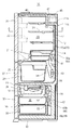
本実施形態の冷蔵庫10は、図1に示すように、前面が開口する断熱箱体11の内部に貯蔵空間が形成され、貯蔵空間は断熱仕切壁16によって上方の冷蔵空間20と下方の冷凍空間30とに区画されている。
As shown in FIG. 1, the
冷蔵空間20は、さらに仕切壁21によって上下に区画され、上部空間に複数段の載置棚23を設けた冷蔵室22が設けられ、下部空間に引き出し式の収納容器25を配置する野菜室24が設けられている。冷凍空間30には、比較的小容積の自動製氷機を備えた製氷室32と小型冷凍室(不図示)を左右に併設しており、その下方には冷凍室36が設けられている。
The refrigerated
冷蔵室22の前面開口部は、断熱箱体11の一側部の上下に設けられたヒンジにより回動自在に枢支された冷蔵室扉26により閉塞されている。野菜室24、製氷室32、小型冷凍室及び冷凍室36の前面開口部は、引き出し式扉27,33,37により閉塞されている。各引き出し式扉27,33,37の裏面側に固着した左右一対の支持枠に収納容器25,34,38が保持されており、開扉動作とともに該支持枠が貯蔵室の内側壁に配設された摺動レールを摺動することで、収納容器25,34,38が庫外に引き出されるように構成されている。
The front opening of the
断熱箱体11の背面上部には、下方に凹んだ段差部11aが設けられており、この段差部11aの上方に冷凍サイクル40の一部を構成する圧縮機45が収納される機械室47が配置され、段差部11aの前方であって断熱箱体11の上面には凝縮器46が配設されている。
A
冷凍サイクル40は、図2に示すように、圧縮機45の吐出側に凝縮器46及び防露パイプ59を介して三方弁48が接続されている。三方弁48から二股に分かれた冷媒流路の一方には冷蔵キャピラリチューブ49及び冷蔵用冷却器41からなる冷蔵側回路が接続され、他方の冷媒流路には冷凍キャピラリチューブ50、冷凍用冷却器42、とからなる冷凍側回路が接続されている。
As shown in FIG. 2, the
三方弁48は、凝縮器46により放熱液化された冷媒を冷蔵側回路及び冷凍側回路へ切り替えて分流し、また、冷蔵側回路及び冷凍側回路への該冷媒供給を遮断する。冷蔵側回路及び冷凍側回路は、圧縮機45の吸込側に接続されており、各冷却器41,42を流れた冷媒が再び圧縮機45に取り込まれることで、冷媒は冷凍サイクル40内を循環する。
The three-
なお、図1における符号39は、冷蔵用冷却器41及び冷凍用冷却器42からの除霜水を受けて貯留し蒸発処理するための蒸発皿であり、断熱箱体11の下方に配置されている。
In addition, the code |
冷蔵空間20の背面には、ダクトカバー53と背面カバー54が配設されており、ダクトカバー53と断熱箱体11の後面との間にダクト51が形成され、背面カバー54と断熱箱体11の後面との間に形成された空間に冷蔵用冷却器41や送風ファン43が収納されている。また、冷凍空間30の背面には、背面カバー55が配設されており、背面カバー55と断熱箱体11の後面との間に形成された空間に冷凍用冷却器42や送風ファン44が収納されている。
A
そして、冷蔵用冷却器41で生成された冷気は、送風ファン43の回転駆動によってダクト51を介して冷蔵室22及び野菜室24に導入されることで、冷蔵空間20を所定温度に冷却する。冷凍用冷却器42で生成された冷気は、送風ファン44の回転駆動によって背面カバー55に設けられた吹出口52より製氷室32、小型冷凍室及び冷凍室36に導入されることで、冷凍空間30を所定温度に冷却する。そして、冷蔵空間20及び冷凍空間30を冷却し終えた冷気は、再び冷却器41,42に戻され冷却される。
And the cold air produced | generated with the
上記構成の冷蔵庫10において、その外郭をなす断熱箱体11は、鋼板からなる外箱12と、外箱12の内部に各貯蔵室22,24,32,36を形成する内箱14と、真空断熱パネル60とを備え、外箱12と内箱14との間に形成された空間のうち、少なくとも断熱部15には真空断熱パネル60のみが配設されている。
In the
より詳細には、内箱14には、図3に例示するような載置棚23やダクトカバー53などの構造物を断熱箱体11の庫内側に配設するために凹凸部56が設けられている。断熱箱体11の庫内側に配設される構造物としては、載置棚23やダクトカバー53以外にも、例えば、背面カバー54、55や、引き出し式扉27,33,37の裏面側に固着した左右一対の支持枠を摺動可能に保持する摺動レールや、冷蔵室22内を照明する庫内灯などが挙げられ、これらの構造物を取り付けるため、載置棚23やダクトカバー53の場合と同様、内箱14には凹凸部56が設けられている。
More specifically, the
断熱部15は、外箱12と内箱14との間に形成された空間であって、凹凸部56を除く内箱14の外側面(すなわち、内箱14における外箱12との対向面)14aを覆う領域に設けられている。この断熱部15には、真空断熱パネル60のみが配設されており、発泡ウレタンなどの発泡断熱材が配設されていない。
The
図1に示すように、内箱14を介して冷凍空間30を臨む下部断熱部15bは、内箱14を介して冷蔵空間20を臨む上部断熱部15aに比べて断熱箱体11の厚さ方向の長さ寸法が大きく設定されており、下部断熱部15bに配設される真空断熱パネル60は、上部断熱部15aに配設される真空断熱パネル60より肉厚に設けられている。
As shown in FIG. 1, the lower
真空断熱パネル60は、綿状のガラス繊維(グラスウール)からなるコア材と、アルミニウム箔と合成樹脂のラミネートフィルムを製袋した厚みが70〜120μmのガスバリア容器とを備え、コア材を収納したガスバリア容器の内部を0.03〜30Pa程度に真空排気した状態でガスバリア容器の端部が密着され封止されている。
The vacuum
なお、冷蔵庫10の上部に配置された上部断熱部15aと、冷蔵庫10の下部に配置された下部断熱部15bとでは、配設される真空断熱パネル60の厚さが異なるが、ガスバリア容器に収納するコア材の厚さを変更したり、あるいは、複数の真空断熱パネル60を重ね合わせることで、上部断熱部15aと下部断熱部15bに配設される真空断熱パネル60の厚さを変更してもよい。
In addition, although the thickness of the vacuum
また、外箱12と内箱14との間に形成された空間であって、断熱部15以外の領域、例えば、凹凸部56や隅角部57には、発泡ウレタンが発泡充填されたり、あるいは発泡スチロールなどの発泡断熱成形体が配設されている(図3参照)。
Further, a space formed between the
つまり、凹凸部56を除いて、内箱14を介して各貯蔵室22,24,32,36を臨む領域には、断熱箱体11の厚さ方向にわたって真空断熱パネル60のみが配設されており、実質的に真空断熱パネル60によって断熱箱体11の断熱性能が確保されている。
That is, only the vacuum
なお、上記した本実施形態では、凹凸部56や隅角部57に発泡断熱成形体を配設したが、発泡断熱成形体に換えて真空断熱パネル60が凹凸部56や隅角部57に配置されても良い。
In the present embodiment described above, the foam heat insulating molded body is disposed in the
また、冷蔵空間20を形成する内箱14と冷凍空間30を形成する内箱14との間には、真空断熱パネル60や発泡断熱成形体を配設して、断熱仕切壁16を形成している。
Further, between the
以上のように本実施形態の冷蔵庫10では、断熱部15に発泡ウレタンなどに比べて比重の大きな真空断熱パネル60のみが配設されているため、重量物である圧縮機45を断熱箱体11の上部に配設しても、冷蔵庫10の重心を低い位置に設けることができ、設置時の安定性を向上させることができる。
As described above, in the
しかも、冷蔵庫10の下部に位置する下部断熱部15bに配設される真空断熱パネル60は、冷蔵庫10の上部に位置する上部断熱部15aに配設される真空断熱パネル60より肉厚に設けられているため、更に冷蔵庫10を低重心化することができ、設置時の安定性をより一層向上させることができる。
Moreover, the vacuum
また、本実施形態の冷蔵庫10では、断熱箱体11の上部に凝縮器46が配設されているため、圧縮機45と凝縮器46とを接続する接続管を配管しやすくなるとともに、凝縮器46は真空断熱パネル60より比重が小さいため、更に冷蔵庫10を低重心化することができ、設置時の安定性をより一層向上させることができる。
Moreover, in the
また、本実施形態の冷蔵庫10では、冷凍用冷却器42からの除霜水を貯留する蒸発皿39が、断熱箱体11の下方に配設されているため、広い領域に蒸発皿39を設けることで蒸発皿39の高さ寸法を小さく設定することができ、真空断熱パネル60をより広範囲にわたって配設することで断熱箱体11からの熱漏洩を抑えることができる。
Moreover, in the
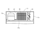
なお、上記した実施形態では、断熱箱体11の背面上部に下方に凹んだ段差部11aを設け、この段差部11aの上方に圧縮機45を収納する機械室47を設けたが、例えば、図4及び図5に示すように、断熱箱体11の背面上部を上方に行くほど前方へ向かって傾斜する傾斜面11bに設け、この傾斜面11bの上方に機械室47を設けてもよい。
In the above-described embodiment, the
このような場合、傾斜面11bの上方において機械室47の底面を構成する底板47aが外箱12の左右の側板12aに固定され、底板47a及び外箱12に囲まれた空間に機械室47が設けられている。機械室47の内部には、圧縮機45と凝縮器46とこれらを冷却するための放熱ファン58が冷蔵庫の幅方向に並べて配置されている。
In such a case, the
10…冷蔵庫 11…断熱箱体 11a…段差部
12…外箱 14…内箱 14a…外側面
15…断熱部 15a…上部断熱部 15b…下部断熱部
16…断熱仕切壁 20…冷蔵空間 22…冷蔵室
23…載置棚 24…野菜室 30…冷凍空間
32…製氷室 36…冷凍室 39…蒸発皿
40…冷凍サイクル 41…冷蔵用冷却器 42…冷凍用冷却器
45…圧縮機 46…凝縮器 47…機械室
51…ダクト 52…吹出口 53…ダクトカバー
54…背面カバー 55…背面カバー 56…凹凸部
57…隅角部 58…放熱ファン 60…真空断熱パネル
DESCRIPTION OF
Claims (6)
前記断熱部には真空断熱パネルのみが配設され、前記断熱箱体の上部に前記圧縮機が配設されていることを特徴とする冷蔵庫。 A heat insulating box having a heat insulating portion formed between the outer box and the inner box; a cooler for cooling the storage chamber provided in the heat insulating box; and a compression for compressing the refrigerant supplied to the cooler. In a refrigerator comprising a compressor and a condenser connected to the discharge side of the compressor,
Only the vacuum heat insulation panel is arrange | positioned at the said heat insulation part, The said compressor is arrange | positioned at the upper part of the said heat insulation box, The refrigerator characterized by the above-mentioned.
Priority Applications (1)
| Application Number | Priority Date | Filing Date | Title |
|---|---|---|---|
| JP2009257140A JP2011102663A (en) | 2009-11-10 | 2009-11-10 | Refrigerator |
Applications Claiming Priority (1)
| Application Number | Priority Date | Filing Date | Title |
|---|---|---|---|
| JP2009257140A JP2011102663A (en) | 2009-11-10 | 2009-11-10 | Refrigerator |
Related Child Applications (1)
| Application Number | Title | Priority Date | Filing Date |
|---|---|---|---|
| JP2014117533A Division JP6005690B2 (en) | 2014-06-06 | 2014-06-06 | refrigerator |
Publications (2)
| Publication Number | Publication Date |
|---|---|
| JP2011102663A true JP2011102663A (en) | 2011-05-26 |
| JP2011102663A5 JP2011102663A5 (en) | 2012-08-30 |
Family
ID=44193062
Family Applications (1)
| Application Number | Title | Priority Date | Filing Date |
|---|---|---|---|
| JP2009257140A Pending JP2011102663A (en) | 2009-11-10 | 2009-11-10 | Refrigerator |
Country Status (1)
| Country | Link |
|---|---|
| JP (1) | JP2011102663A (en) |
Cited By (12)
| Publication number | Priority date | Publication date | Assignee | Title |
|---|---|---|---|---|
| JP2012255606A (en) * | 2011-06-09 | 2012-12-27 | Toshiba Corp | Refrigerator |
| JP2014006039A (en) * | 2012-06-27 | 2014-01-16 | Toshiba Corp | Heat insulation box |
| JP2014044035A (en) * | 2012-08-29 | 2014-03-13 | Hitachi Appliances Inc | Refrigerator |
| JP2015227762A (en) * | 2014-06-02 | 2015-12-17 | 株式会社東芝 | refrigerator |
| JPWO2014196220A1 (en) * | 2013-06-07 | 2017-02-23 | 三菱電機株式会社 | refrigerator |
| JP2017150811A (en) * | 2013-06-07 | 2017-08-31 | 三菱電機株式会社 | refrigerator |
| JP2017161125A (en) * | 2016-03-08 | 2017-09-14 | 日立アプライアンス株式会社 | refrigerator |
| JP2017194271A (en) * | 2013-06-07 | 2017-10-26 | 三菱電機株式会社 | refrigerator |
| JP2018084411A (en) * | 2016-08-25 | 2018-05-31 | 東芝ライフスタイル株式会社 | Heat insulation box body |
| JP2019039665A (en) * | 2018-10-30 | 2019-03-14 | 東芝ライフスタイル株式会社 | refrigerator |
| JP2020024086A (en) * | 2019-11-06 | 2020-02-13 | 東芝ライフスタイル株式会社 | refrigerator |
| JP7391897B2 (en) | 2019-11-06 | 2023-12-05 | 東芝ライフスタイル株式会社 | refrigerator |
Citations (14)
| Publication number | Priority date | Publication date | Assignee | Title |
|---|---|---|---|---|
| JPS5663980U (en) * | 1979-10-24 | 1981-05-29 | ||
| JPS6073281A (en) * | 1983-09-30 | 1985-04-25 | 株式会社日立製作所 | Vacuum heat-insulating box body |
| JPS6078276A (en) * | 1983-10-03 | 1985-05-02 | 松下冷機株式会社 | Manufacture of heat-insulating box body |
| JPS60156378U (en) * | 1984-03-27 | 1985-10-18 | 大和冷機工業株式会社 | horizontal refrigerator |
| JPS6273075A (en) * | 1986-06-24 | 1987-04-03 | 三洋電機株式会社 | Method of mounting base for compressor |
| JPH0798174A (en) * | 1993-09-30 | 1995-04-11 | Toshiba Corp | Vacuum thermal insulating panel and thermal insulating case |
| JPH0861834A (en) * | 1994-08-18 | 1996-03-08 | Toshiba Corp | Heat insulation box and manufacture thereof |
| JPH0882475A (en) * | 1994-09-13 | 1996-03-26 | Toshiba Corp | Heat insulating box body |
| JPH08285437A (en) * | 1995-04-13 | 1996-11-01 | Matsushita Refrig Co Ltd | Compact cooling apparatus |
| JP2002090048A (en) * | 2000-09-14 | 2002-03-27 | Matsushita Refrig Co Ltd | Refrigerator |
| JP2005351508A (en) * | 2004-06-09 | 2005-12-22 | Matsushita Electric Ind Co Ltd | Refrigerator |
| JP2006118792A (en) * | 2004-10-21 | 2006-05-11 | Matsushita Electric Ind Co Ltd | Refrigerator |
| JP2006138582A (en) * | 2004-11-15 | 2006-06-01 | Matsushita Electric Ind Co Ltd | Refrigerator |
| JP2006194571A (en) * | 2004-06-09 | 2006-07-27 | Matsushita Electric Ind Co Ltd | Refrigerator |
-
2009
- 2009-11-10 JP JP2009257140A patent/JP2011102663A/en active Pending
Patent Citations (14)
| Publication number | Priority date | Publication date | Assignee | Title |
|---|---|---|---|---|
| JPS5663980U (en) * | 1979-10-24 | 1981-05-29 | ||
| JPS6073281A (en) * | 1983-09-30 | 1985-04-25 | 株式会社日立製作所 | Vacuum heat-insulating box body |
| JPS6078276A (en) * | 1983-10-03 | 1985-05-02 | 松下冷機株式会社 | Manufacture of heat-insulating box body |
| JPS60156378U (en) * | 1984-03-27 | 1985-10-18 | 大和冷機工業株式会社 | horizontal refrigerator |
| JPS6273075A (en) * | 1986-06-24 | 1987-04-03 | 三洋電機株式会社 | Method of mounting base for compressor |
| JPH0798174A (en) * | 1993-09-30 | 1995-04-11 | Toshiba Corp | Vacuum thermal insulating panel and thermal insulating case |
| JPH0861834A (en) * | 1994-08-18 | 1996-03-08 | Toshiba Corp | Heat insulation box and manufacture thereof |
| JPH0882475A (en) * | 1994-09-13 | 1996-03-26 | Toshiba Corp | Heat insulating box body |
| JPH08285437A (en) * | 1995-04-13 | 1996-11-01 | Matsushita Refrig Co Ltd | Compact cooling apparatus |
| JP2002090048A (en) * | 2000-09-14 | 2002-03-27 | Matsushita Refrig Co Ltd | Refrigerator |
| JP2005351508A (en) * | 2004-06-09 | 2005-12-22 | Matsushita Electric Ind Co Ltd | Refrigerator |
| JP2006194571A (en) * | 2004-06-09 | 2006-07-27 | Matsushita Electric Ind Co Ltd | Refrigerator |
| JP2006118792A (en) * | 2004-10-21 | 2006-05-11 | Matsushita Electric Ind Co Ltd | Refrigerator |
| JP2006138582A (en) * | 2004-11-15 | 2006-06-01 | Matsushita Electric Ind Co Ltd | Refrigerator |
Cited By (14)
| Publication number | Priority date | Publication date | Assignee | Title |
|---|---|---|---|---|
| JP2012255606A (en) * | 2011-06-09 | 2012-12-27 | Toshiba Corp | Refrigerator |
| JP2014006039A (en) * | 2012-06-27 | 2014-01-16 | Toshiba Corp | Heat insulation box |
| JP2014044035A (en) * | 2012-08-29 | 2014-03-13 | Hitachi Appliances Inc | Refrigerator |
| JP2018169159A (en) * | 2013-06-07 | 2018-11-01 | 三菱電機株式会社 | refrigerator |
| JPWO2014196220A1 (en) * | 2013-06-07 | 2017-02-23 | 三菱電機株式会社 | refrigerator |
| JP2017150811A (en) * | 2013-06-07 | 2017-08-31 | 三菱電機株式会社 | refrigerator |
| JP2017194271A (en) * | 2013-06-07 | 2017-10-26 | 三菱電機株式会社 | refrigerator |
| JP2018063110A (en) * | 2013-06-07 | 2018-04-19 | 三菱電機株式会社 | refrigerator |
| JP2015227762A (en) * | 2014-06-02 | 2015-12-17 | 株式会社東芝 | refrigerator |
| JP2017161125A (en) * | 2016-03-08 | 2017-09-14 | 日立アプライアンス株式会社 | refrigerator |
| JP2018084411A (en) * | 2016-08-25 | 2018-05-31 | 東芝ライフスタイル株式会社 | Heat insulation box body |
| JP2019039665A (en) * | 2018-10-30 | 2019-03-14 | 東芝ライフスタイル株式会社 | refrigerator |
| JP2020024086A (en) * | 2019-11-06 | 2020-02-13 | 東芝ライフスタイル株式会社 | refrigerator |
| JP7391897B2 (en) | 2019-11-06 | 2023-12-05 | 東芝ライフスタイル株式会社 | refrigerator |
Similar Documents
| Publication | Publication Date | Title |
|---|---|---|
| JP2011102663A (en) | Refrigerator | |
| JP4488966B2 (en) | refrigerator | |
| TW200928263A (en) | Refrigerator | |
| JP2006329482A (en) | Refrigerator | |
| JP2007071521A (en) | Refrigerator | |
| JP5175705B2 (en) | refrigerator | |
| WO2007010267A2 (en) | Improvements in or relating to cold storage | |
| JP3969434B2 (en) | refrigerator | |
| JP2016090079A (en) | refrigerator | |
| JP3722151B1 (en) | refrigerator | |
| JP2003222466A (en) | Refrigerator | |
| JP6005690B2 (en) | refrigerator | |
| JP2009156527A (en) | Refrigerator | |
| JP2008138903A (en) | Refrigerator | |
| JP7390178B2 (en) | refrigerator | |
| JP2007271241A (en) | Storage | |
| JP2003166781A (en) | Refrigerator | |
| JP5271134B2 (en) | Freezer refrigerator | |
| JP2019032161A (en) | refrigerator | |
| JP7430524B2 (en) | refrigerator | |
| JP5461862B2 (en) | refrigerator | |
| JP5431763B2 (en) | Freezer refrigerator | |
| JP5607890B2 (en) | refrigerator | |
| JP2003166775A (en) | Refrigerator | |
| JPH08247638A (en) | Refrigerator |
Legal Events
| Date | Code | Title | Description |
|---|---|---|---|
| A521 | Written amendment |
Free format text: JAPANESE INTERMEDIATE CODE: A523 Effective date: 20120711 |
|
| A621 | Written request for application examination |
Free format text: JAPANESE INTERMEDIATE CODE: A621 Effective date: 20120711 |
|
| A977 | Report on retrieval |
Free format text: JAPANESE INTERMEDIATE CODE: A971007 Effective date: 20130725 |
|
| A131 | Notification of reasons for refusal |
Free format text: JAPANESE INTERMEDIATE CODE: A131 Effective date: 20130820 |
|
| A521 | Written amendment |
Free format text: JAPANESE INTERMEDIATE CODE: A523 Effective date: 20131016 |
|
| A711 | Notification of change in applicant |
Free format text: JAPANESE INTERMEDIATE CODE: A712 Effective date: 20140204 |
|
| A02 | Decision of refusal |
Free format text: JAPANESE INTERMEDIATE CODE: A02 Effective date: 20140311 |
|
| A521 | Written amendment |
Free format text: JAPANESE INTERMEDIATE CODE: A523 Effective date: 20140606 |
|
| A911 | Transfer of reconsideration by examiner before appeal (zenchi) |
Free format text: JAPANESE INTERMEDIATE CODE: A911 Effective date: 20140613 |
|
| A912 | Removal of reconsideration by examiner before appeal (zenchi) |
Free format text: JAPANESE INTERMEDIATE CODE: A912 Effective date: 20140808 |