JP2011102479A - Fireproof structure - Google Patents
Fireproof structure Download PDFInfo
- Publication number
- JP2011102479A JP2011102479A JP2009257237A JP2009257237A JP2011102479A JP 2011102479 A JP2011102479 A JP 2011102479A JP 2009257237 A JP2009257237 A JP 2009257237A JP 2009257237 A JP2009257237 A JP 2009257237A JP 2011102479 A JP2011102479 A JP 2011102479A
- Authority
- JP
- Japan
- Prior art keywords
- frp
- fireproof
- insert
- support shaft
- layer
- Prior art date
- Legal status (The legal status is an assumption and is not a legal conclusion. Google has not performed a legal analysis and makes no representation as to the accuracy of the status listed.)
- Pending
Links
Images


Landscapes
- Building Environments (AREA)
Abstract
Description
本発明は、FRP構造体の表面の少なくとも一部に耐火層を設けた耐火構造体に関する。 The present invention relates to a fireproof structure in which a fireproof layer is provided on at least a part of the surface of an FRP structure.
耐火構造体として、特に大型構造体を構成する場合は、軽量性を確保しつつ、強度、剛性を確保する必要がある。このため、コア材の両面にFRP層が配置されたサンドイッチ構造のものが使用されている(例えば、特許文献1参照)。
更に、耐火構造体として、その一部を構成するFRP材の少なくとも片面に無機質発泡体または無機質マットを積層して一体成形したものも知られている(例えば、特許文献2参照)。
In particular, when a large-sized structure is configured as the fireproof structure, it is necessary to ensure strength and rigidity while ensuring lightness. For this reason, the thing of the sandwich structure where the FRP layer is arrange | positioned on both surfaces of a core material is used (for example, refer patent document 1).
Further, a fireproof structure is also known which is integrally formed by laminating an inorganic foam or an inorganic mat on at least one side of an FRP material constituting a part thereof (see, for example, Patent Document 2).
特許文献1に係る耐火構造体は、その主構成部分としてFRP構造体が使用されており、大型の建材として、例えば屋根材を構成する場合は、軽量性をもたせつつそのFRP屋根に高い剛性を付与することで、柱、梁の間隔を多くとって空間が確保されるようになっている。 The fire-resistant structure according to Patent Document 1 uses an FRP structure as its main component, and, for example, when a roofing material is configured as a large building material, the FRP roof has high rigidity while being lightweight. By giving it, the space between the columns and the beams is increased to secure the space.
FRP屋根材は、火災時の性能を維持するため耐火層を用いている。この耐火層は、単層または多層のいずれの構造でも良く、多層構造(サンドイッチ構造)における耐火層の固定法としては、タッピング止め、接着剤、ベルト止め、固定ピン等の方法が採られている。 The FRP roofing material uses a refractory layer in order to maintain the performance at the time of fire. This refractory layer may be either a single layer or a multilayer structure, and as a method for fixing the refractory layer in the multilayer structure (sandwich structure), methods such as tapping, adhesive, belt fixing, and fixing pins are adopted. .
特許文献2に係る耐火構造体は、無機質発泡体または無機質マットの積層として、接着、貼り付け、融着、縫着などにより一体固定することで熱源から断熱保護されるので、FRP材は強度の低下、軟化、燃焼することなく安定し、形態保護されるようになっている。
Since the fireproof structure according to
特許文献1に係る耐火構造体では、耐火層の固定に際しボルトやリベット、タッピングネジを用いてコア材の両面に配置されたFRP板材を貫通して一体固定するもので、サンドイッチ構造が構成される。 In the fire-resistant structure according to Patent Document 1, a sandwich structure is configured by penetrating and fixing FRP plate members disposed on both surfaces of the core material using bolts, rivets, and tapping screws when fixing the fire-resistant layer. .
特許文献2に係る耐火構造体では、FRP材の少なくとも片面に無機質発泡体または無機質マットを積層、配置して、接着、貼り付け、融着、縫着などにより一体固定されている。
In the fireproof structure according to
従って、特許文献1に係る耐火層の固定法では、サンドイッチ構造を構成するために、ボルトやリベット、タッピングネジ(以下、止め具と称する)をコア材両面のFRP板材を貫通して一体固定する方法を採っているので、ボルトを用いると、貫通した止め具の先端がFRP板材の裏面から突出する。例えば、FRP板材の裏面側を化粧板などとして使用する場合は、平坦な裏面側FRP板材から突出した止め具の先端が邪魔になるだけでなく、壁面の美観が損なわれる問題を有している。また、止め具にタッピングネジなどを用いると、耐火層の取り外しが困難で引き抜き強度が低下する問題を有している。 Therefore, in the fixing method of the refractory layer according to Patent Document 1, in order to form a sandwich structure, bolts, rivets, and tapping screws (hereinafter referred to as stoppers) are integrally fixed through the FRP plate materials on both surfaces of the core material. Since the method is employed, when a bolt is used, the tip of the penetrating stopper protrudes from the back surface of the FRP plate material. For example, when the back side of the FRP plate material is used as a decorative plate or the like, the front end of the stopper projecting from the flat back side FRP plate material not only gets in the way, but the appearance of the wall surface is impaired. . In addition, when a tapping screw or the like is used as a stopper, there is a problem that it is difficult to remove the fireproof layer and the pullout strength is lowered.
また、特許文献2に係る耐火層の固定法では、FRP材の少なくとも片面に無機質発泡体または無機質マットを積層、配置し、接着剤などを用いて一体固定されるので、火災時に接着剤やFRP樹脂が燃焼したり熱分解したりして、耐火層が脱落し易くなり、耐熱性の接着剤を用いたとしても広い面積で接着が必要となるので施工工数が増加する問題を有している。
Moreover, in the fixing method of the refractory layer according to
本発明は、上述した事情に鑑みてなされたもので、FRP構造体の表面に好適に耐火層を設置できる共に、耐火層の取付け、取外し作業が容易で施工工数の削減を図ることができる耐火構造体を提供することを目的とする。 The present invention has been made in view of the above-described circumstances, and it is possible to suitably install a fireproof layer on the surface of the FRP structure, and it is easy to attach and remove the fireproof layer and to reduce the number of construction steps. An object is to provide a structure.
本発明に係る耐火構造体では、上記課題を解決するために以下の手段を採用した。
本発明に係る耐火構造体は、FRP構造体の表面の少なくとも一部に無機質の綿状繊維からなる耐火層を設けた耐火構造体であって、前記FRP構造体に支持軸体を埋め込み接合し、前記支持軸体と該支持軸体に螺合するねじ部材で前記耐火層を挟持して固定したことを特徴とする。
The fireproof structure according to the present invention employs the following means in order to solve the above problems.
The fireproof structure according to the present invention is a fireproof structure in which a fireproof layer made of inorganic cotton-like fibers is provided on at least a part of the surface of the FRP structure, and a support shaft is embedded in the FRP structure. The fireproof layer is sandwiched and fixed by the support shaft body and a screw member screwed to the support shaft body.
本発明によれば、FRP構造体に埋め込み接合した支持軸体にねじ部材を螺合することで、支持軸体がFRP構造体を貫通せずに耐火層を挟持、固定することができる。これにより、支持軸体が突出しないFRP構造体の面を化粧板として使用することができる。また、支持軸体に対しねじ部材を着脱することで、耐火層の取付け、取外し作業が容易となり耐火構造体の施工工数を削減することができる。 According to the present invention, the fire-resistant layer can be sandwiched and fixed without screwing the support member into the FRP structure by screwing the screw member into the support shaft that is embedded and joined to the FRP structure. Thereby, the surface of the FRP structure which a support shaft does not protrude can be used as a decorative board. Moreover, by attaching / detaching the screw member to / from the support shaft body, it is easy to attach and remove the fireproof layer, and the number of construction steps for the fireproof structure can be reduced.
また、本発明に係る耐火構造体は、FRP構造体の表面の少なくとも一部に無機質の綿状繊維からなる耐火層を設けた耐火構造体であって、前記FRP構造体の表面に支持軸体を接合し、前記支持軸体と該支持軸体に螺合するねじ部材で前記耐火層を挟持して固定したことを特徴とする。 The fire-resistant structure according to the present invention is a fire-resistant structure in which a fire-resistant layer made of inorganic cotton-like fibers is provided on at least a part of the surface of the FRP structure, and a support shaft body is provided on the surface of the FRP structure. And the fireproof layer is sandwiched and fixed by the support shaft body and a screw member screwed to the support shaft body.
本発明によれば、FRP構造体の表面に接合した支持軸体にねじ部材を螺合することで支持軸体がFRP構造体を貫通せずに耐火層を挟持して固定することができる。これにより、耐火層の取付け、取外し作業が容易になるだけでなく、広い面積での接着が不要となるので耐火構造体の施工工数を削減することができ、接着剤に耐熱性のものを用いることで火災時における耐火層の脱落を防止することができる。 According to the present invention, the screw member is screwed to the support shaft body joined to the surface of the FRP structure, whereby the support shaft body can sandwich and fix the refractory layer without penetrating the FRP structure. This not only facilitates the attachment and removal of the refractory layer, but also eliminates the need for bonding over a large area, thus reducing the number of construction steps for the refractory structure and using a heat-resistant adhesive. Therefore, it is possible to prevent the fireproof layer from falling off during a fire.
また、前記支持軸体は一端にフランジ部を有し、前記フランジ部を前記FRP構造体に接合したことを特徴とする。
これにより、支持軸体のフランジ部をFRP構造体に接合することで、支持軸体の他端に設けた螺子にねじ部材(ナット)を螺合して耐火層を挟持して固定すれば、耐火層の取付け、取外し作業を容易に行うことができる。
The support shaft has a flange at one end, and the flange is joined to the FRP structure.
Accordingly, by joining the flange portion of the support shaft body to the FRP structure, the screw member (nut) is screwed to the screw provided at the other end of the support shaft body, and the fireproof layer is sandwiched and fixed. Attaching and removing the fireproof layer can be performed easily.
前記支持軸体は、セラミックス又はセラミックス系複合材料からなることを特徴とする。
これにより、支持軸体にセラミックス又はセラミックス系複合材料を用いることで、耐熱性ならびに機械的強度を有する。これにより、火災時における耐火層の脱落を防止することができる。
The support shaft body is made of ceramics or a ceramic composite material.
Thereby, it has heat resistance and mechanical strength by using ceramics or a ceramic composite material for the support shaft. As a result, it is possible to prevent the fire-resistant layer from falling off during a fire.
前記支持軸体は、フェノール樹脂、ポリイミド樹脂又はエポキシ樹脂からなることを特徴とする。
これにより、支持軸体を耐熱性の高い樹脂で一体成型することで、火災時における耐火層の脱落を防止することができる。
The support shaft body is made of a phenol resin, a polyimide resin, or an epoxy resin.
As a result, the support shaft body is integrally formed of a resin having high heat resistance, so that the fireproof layer can be prevented from falling off during a fire.
前記支持軸体と前記FRP構造体の接合に、接着剤又はコーキング材を用いたことを特徴とする。
これにより、例えば無機系接着剤は1400℃の高温に耐える耐熱性を有し、作業性に優れた性質も備えているので、施工性が良く火災時における耐火層の保持が安定する。また、耐食性、耐摩耗性、耐有機溶剤が要求される場所にも使用することができる。
また、シーリング材となるシリコン樹脂系、又はポリマーラテックス系などのパテ状の充填剤となるコーキング材を支持軸体の接合に用いることで、軽量で断熱性、耐熱性に優れた性質を有しており、火災時における耐火層の保持が安定する。
An adhesive or a caulking material is used for joining the support shaft body and the FRP structure.
Thereby, for example, the inorganic adhesive has heat resistance that can withstand a high temperature of 1400 ° C. and has excellent workability, so that the workability is good and the holding of the fire-resistant layer is stable during a fire. It can also be used in places where corrosion resistance, abrasion resistance, and organic solvents are required.
In addition, by using a caulking material that is a putty-like filler such as a silicone resin or polymer latex as a sealing material for joining the support shaft body, it has properties that are lightweight and have excellent heat insulation and heat resistance. The fireproof layer is maintained stably in the event of a fire.
本発明によれば、支持軸体によるFRP構造体の接合に際し、FRP構造に埋め込み接合した支持軸体にねじ部材を螺合することで、支持軸体がFRP構造体を貫通せずに耐火層を挟持、固定することができる。これにより、支持軸体が突出しないFRP構造体の表面側を化粧板等として有効に使用することができる。また、耐火層の取付け、取外し作業が単純化されるので耐火構造体の施工工数を削減することができる。更に、耐熱性の支持軸体並びに接着剤を用いることで、火災時における耐火層の脱落を防止することができる。 According to the present invention, when the FRP structure is joined by the support shaft, the screw member is screwed into the support shaft embedded and joined in the FRP structure, so that the support shaft does not penetrate the FRP structure and the refractory layer is formed. Can be clamped and fixed. Thereby, the surface side of the FRP structure in which the support shaft does not protrude can be used effectively as a decorative board or the like. In addition, since the work of attaching and removing the refractory layer is simplified, the number of man-hours for constructing the refractory structure can be reduced. Furthermore, by using a heat-resistant support shaft and an adhesive, it is possible to prevent the fire-resistant layer from falling off during a fire.
以下、本発明に係る耐火構造体の実施形態につき図面を参照して説明する。
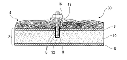
図1は、第一実施形態に係る耐火構造体の断面図を示している。図1において、第一実施形態に係る耐火構造体1は、2枚のFRP材6,8と、これらFRP材6,8の間にコア材10が配置されたサンドイッチ構造のFRP構造体2として構成される。
Hereinafter, an embodiment of a fireproof structure according to the present invention will be described with reference to the drawings.
FIG. 1 shows a cross-sectional view of the refractory structure according to the first embodiment. 1, the fireproof structure 1 according to the first embodiment is an
FRP材6,8は、強化繊維やマトリックス樹脂に限定されるものではないが、強化繊維として、炭素繊維、ガラス繊維、アラミド繊維等を使用することできる。また、マトリックス樹脂としては、エポキシ樹脂、フェノール樹脂、不飽和ポリエステル樹脂、ビニルエステル樹脂などの熱硬化性樹脂の他、各種熱可塑性樹脂も使用できる。中でも、耐火性能に優れたフェノール樹脂を用いることが好ましい。
The
コア材10としては、木材や発泡体、ハニカム体などを使用することができ、軽量性の点からは、比重の小さい発泡体がより好ましい。特にこのようなコア材10の使用により、剛性のみならず、断熱性や遮音性も向上できる。耐火性を重視する場合は、耐火性能に優れたフェノール樹脂を用いることができる。
As the
FRP構造体2は、一定幅で長手方向に延びており断面形状も略一定または長手方向に延びているが、実質的に一定の幅を有する限り断面形状は必要に応じて円弧状に形成することもできる。
The
FRP構造体2の表面の少なくとも一部には、無機質の綿状繊維からなる耐火層4が、後述するインサート12とこのインサート12に螺合するねじ部材16により挟持されて取付けられる。耐火層4を形成する綿状繊維には、ロックウールやセラミック繊維などが好適である。
On at least a part of the surface of the
次に、第一実施形態の耐火構造体1における耐火層4の取付け例に付き説明する。
図1に示されるインサート12は、耐熱性の素材で棒状(軸状)に形成されて上端にねじが螺設されている。
FRP構造体2の表面側には、FRP材6及びコア材10に対して一体にあけられた、複数の挿通孔H(図1では1個のみ図示)が形成されている。この挿通孔Hは、棒状のインサート12の外径に対し同径または若干小径に形成されており、挿通したインサート12を締り嵌めで嵌着保持できるようになっている。
挿通孔HからFRP構造体2に差し込まれたインサート12は、その下端がコア材10の内部に埋め込まれてFRP構造体2の表面に立設保持される。
Next, it attaches and demonstrates to the example of attachment of the fireproof layer 4 in the fireproof structure 1 of 1st embodiment.
The
A plurality of insertion holes H (only one is shown in FIG. 1) formed integrally with the
The lower end of the
ここで、立設したインサート12は、FRP構造体2表面側のFRP材6上面に敷設された耐火層4の上面から上端が突き出た状態となっている。
そこで、インサート12の上端から座金18を介してねじ部材となるナット16をねじに螺合し、これを締め上げることで、耐火層4は、インサート12とナット16により挟持されてFRP構造体2表面側のFRP材6上面に保持される。
Here, the erected
Therefore, the
このように、インサート12の先端がFRP構造体2を貫通せずに耐火層4を固定することで、インサート12が突出しないFRP構造体2の裏面を化粧板として使用することができる。また、インサート12に対しナット16を着脱することで、耐火層4の取付け、取外し作業を容易に行うことができる。
これにより、耐火構造体1の施工工数を削減することができる。
Thus, the back surface of the
Thereby, the construction man-hour of the fireproof structure 1 can be reduced.
ここで、インサート12は、セラミックス、セラミックス系複合材料等の耐熱性の素材として構成される。特に、軽量多孔質のSiC系セラミックス複合材を用いることで、耐熱、耐蝕、熱衝撃性を向上することができる。
Here, the
また、インサート12は、耐燃性に優れ、熱硬化性樹脂として知られるフェノール、ポリイミド、エポキシ樹脂で構成することもできる。特に、フェノール、エポキシ樹脂は、機械的強度を有している。
Moreover, the
これにより、インサート12は、従来の鋼やアルミニウム合金などの金属材料以外にセラミックス又はセラミックス系複合材料、またはフェノール、ポリイミド、エポキシ樹脂で構成することにより、火災時における耐火層の脱落を防止することができる。
In this way, the
次に、第二実施形態に係る耐火構造体20における耐火層4の取付け例に付き図2を参照して説明する。
図2は、第二実施形態に係る耐火構造体の断面図を示しており、第二実施形態では、第一実施形態で述べた構成部材と同一部材については同一符号を記し、重複する説明を省略し、以下の説明も同様とする。
Next, an attachment example of the fireproof layer 4 in the
FIG. 2 shows a cross-sectional view of the refractory structure according to the second embodiment. In the second embodiment, the same members as the constituent members described in the first embodiment are denoted by the same reference numerals, and redundant descriptions are provided. It is omitted and the following description is the same.
第二実施形態におけるインサート22は、第一実施形態のインサート12に対し下端側が長く形成されている。挿通孔Hは、第一実施形態と同様に棒状のインサート14の外径に対し同径または若干小径に形成されていて、インサート22を締まり嵌めにより嵌着保持されている。
In the
複数の挿通孔H(図2では1個のみ図示)を挿通したインサート22の下端は、FRP構造体2裏面側のFRP材8の内壁面に当接保持される。
The lower end of the
ここで、インサート22による耐火層4の取付け作用及び効果は、第一実施形態と同一であるため説明を省略するが、第二実施形態ではインサート22は、FRP構造体2裏面側のFRP材8の内壁面に下端が当接し、挿通孔Hに差し込まれた状態でFRP構造体2に埋め込まれる。
これにより、FRP構造体2のコア材10内部に埋め込まれたインサート22が支柱として構成されるので、FRP構造体2の剛性が高められインサート22の垂直保持力が安定する。
Here, the mounting action and effect of the fireproof layer 4 by the
Thereby, since the
次に、第三実施形態に係る耐火構造体30における耐火層4の取付け例に付き、図3を参照して説明する。
図3に示されるインサート32は、第一実施形態と同様に耐熱性の素材で棒状に形成されて、上端にはねじが螺設されている。FRP構造体2表面側のFRP材6には、複数の挿通孔H(図3では1個のみ図示)が形成されている。
Next, it attaches to the example of attachment of the fireproof layer 4 in the
The
この挿通孔Hは、インサート32よりも挿通可能な若干大きな内径で形成されており、内壁に接着剤Bが塗布された挿通孔Hにインサート32が挿し込まれて接着固定される。
これにより、インサート32は、FRP構造体2表面側のFRP材6に安定状態で立設保持することができる。
The insertion hole H is formed with a slightly larger inner diameter that can be inserted through the
Thereby, the
無機系接着剤Bは、1400℃の高温に耐える耐熱性を有しており、この無機系接着剤Bを用いてインサート32がFRP構造体2表面側のFRP材6上面に接着固定されるので、火災時における耐火層の保持が安定し脱落を防止することができる。
また、無機系接着剤Bは、作業性に優れた性質も備えているので、施工性も良く、耐食性、耐摩耗性、耐有機溶剤が要求される場所にも使用することができる。
The inorganic adhesive B has heat resistance that can withstand a high temperature of 1400 ° C., and the
In addition, since the inorganic adhesive B also has excellent workability, it has good workability and can be used in places where corrosion resistance, wear resistance, and organic solvent resistance are required.
更に、無機系接着剤Bに代えて、接合にコーキング材を用いることもできる。このコーキング材は、軽量で断熱性、耐熱性に優れた性質を有しており、シーリング材となるシリコン樹脂系、又はポリマーラテックス(例えば、住友3M社製CP−25WB等)のパテ状の充填剤となるもので、これをインサート32の接着剤Bとして用いることで火災時における耐火層の保持が安定する。
Furthermore, instead of the inorganic adhesive B, a caulking material can be used for bonding. This caulking material is lightweight, has excellent properties of heat insulation and heat resistance, and putty-like filling of silicone resin or polymer latex (for example, CP-25WB manufactured by Sumitomo 3M) as a sealing material By using this as the adhesive B of the
次に、第四実施形態に係る耐火構造体40における耐火層4の取付け例に付き図4を参照して説明する。
第四実施形態におけるインサート42は、第三実施形態のインサート32に対し下端側が長く形成されている。挿通孔Hは、第三実施形態と同様に棒状のインサート42が挿通可能な若干大きな内径で形成されている。
挿通孔Hを挿通したインサート42の下端は、FRP構造体2に差し込まれ、インサート42の下端側がFRP構造体2裏面側のFRP材8の内壁面に当接保持される。
Next, an example of attaching the refractory layer 4 in the
In the
The lower end of the
この挿通孔Hは、インサート42よりも挿通可能な若干大きな内径で形成されており、内壁に接着剤Bが塗布された挿通孔Hにインサート42が挿し込まれて接着固定される。
これにより、インサート42は、FRP構造体2表面側のFRP材6に安定状態で立設保持することができる。
The insertion hole H is formed with a slightly larger inner diameter that can be inserted through the
Thereby, the
尚、インサート42によりFRP構造体2に与える作用、効果は第二実施形態と同一であり、またインサート42による耐火層4の取付け作用及び効果は第一実施形態と同一であるため説明を省略する。
The action and effect given to the
次に、第五実施形態に係る耐火構造体50に付き、図5を参照して説明する。
第五実施形態に係る耐火構造体50のインサート52は、耐熱性の素材で円柱状(フランジ部)の形成された台座54と、この台座54の中央から上方に立設したねじ軸55とから一体的に構成されている。
Next, it attaches | subjects to the
The
FRP構造体2表面側のFRP材6には、複数の複数の大径挿通孔56(図5では1個のみ図示)が形成されており、この大径挿通孔56に台座54が挿嵌保持されて、コア材10の内部に形成された保持穴58内に挿入され、下面がFRP構造体2裏面側のFRP材8の内壁面に当接している。
A plurality of large-diameter insertion holes 56 (only one is shown in FIG. 5) are formed in the
大径挿通孔56は、台座54の外径と同一、又は若干小径又は若干大径に形成されて、大径挿通孔56を挿通した台座54を締まり嵌め又は接着により保持できるように構成されており、コア材10内部の保持穴58も大径挿通孔56と同径または若干小径又は若干大径に形成されている。
The large-
そこで、大径挿通孔56並びに保持穴58にインサート52の台座54が締まり嵌め又は接着により保持されて、埋め込み接合されると、耐火層4の上面からねじ軸55の上端が突き出た状態となり、ねじ軸55の上端から座金18を介してナット16をねじ軸55のねじに螺合する。
次いで、ナット16を締め上げることで、耐火層4は、インサート52の台座54とナット16により挟持された状態でFRP構造体2表面側のFRP材6上面に固定される。
Therefore, when the
Next, by tightening the
なお、図5では、インサート52の台座54がFRP材8の内壁面に当接している場合を図示したが、必ずしも台座54がFRP材8の内壁面に当接しなくてもよい。
5 illustrates the case where the
次に、第六実施形態に係る耐火構造体60に付き、図6を参照して説明する。
第六実施形態に係る耐火構造体60のピン62は、第一〜第五実施形態と同様に耐熱性の素材で棒状に形成されて一端にねじが螺設されている。ピン62の他端が、接着剤Bにより接着接合されてFRP構造体2表面側のFRP材6上面に立設保持されている。
Next, the
As in the first to fifth embodiments, the
そこで、FRP構造体2表面側のFRP材6上面に敷設された耐火層4からピン62の一端が突出しており、このピン62一端のねじ部に座金18を介してナット16を螺合する。
これにより、耐火層4は、ピン62とナット16により座金18を介して挟持されてFRP材6上面に保持される。
Therefore, one end of the
As a result, the refractory layer 4 is held between the
次に、第七実施形態に係る耐火構造体70に付き、図7を参照して説明する。
第七実施形態に係る耐火構造体70に用いられるピン72は、耐熱性の素材で円板状に形成されたフランジ部74と、このフランジ部74の中央から上方に立設し上端にねじ部を有するねじ軸75ととから一体的に構成されている。
Next, the
The
そこで、ピン72は、フランジ部74の外周及び底面が接着剤BによりFRP構造体2表面側のFRP材6上面に接着接合されてFRP構造体2表面側のFRP材6上面に立設保持される。
これにより、耐火層4はピン72のフランジ部74とナット16により座金18を介して挟持されてFRP材6上面に保持される。
Thus, the outer periphery and bottom surface of the
As a result, the refractory layer 4 is held between the
次に、耐火構造体の第八実施形態に耐火構造体80に付き、図8を参照して説明する。
第八実施形態に耐火構造体80は、FRP構造体2表面側のFRP材6上面に敷設された耐火層4を取り付けるためのインサート82とボルト84を具備している。
インサート82は、耐熱性の素材で円柱状のブロックで形成されており、中央にはねじ孔TH(タップ)が穿設されており、ねじ孔THにはボルト84が螺合可能とされている。
Next, the eighth embodiment of the fireproof structure is attached to the
The
The
FRP構造体2表面側のFRP材6には、複数の複数の大径挿通孔86(図8では1個のみ図示)が形成されている。この大径挿通孔86は後述する円柱状のインサート82の外径と同一、又は若干小径、又は若干大径に形成されており、この大径挿通孔86に円柱状のインサート82が締まり嵌め又は接着により保持される。
そして、インサート82は、コア材10の内部に形成された保持穴88内に挿入されて埋め込み接合され、その下端面がFRP構造体2裏面側のFRP材8の内壁面に当接している。
A plurality of large-diameter insertion holes 86 (only one is shown in FIG. 8) are formed in the
The
そこで、FRP構造体2表面側のFRP材6上面に敷設された耐火層4の上面からボルト84をピン62中央上面のねじ孔THに螺挿し、インサート82とボルト84の頭部により座金18を介して耐火層4が挟持されてFRP材6上面に保持される。
Therefore, the
最後に、耐火構造体の第九実施形態に耐火構造体90に付き、図9を参照して説明する。
第九実施形態に耐火構造体90は、は、FRP構造体2表面側のFRP材6上面に敷設された耐火層4を取り付けるために一端にねじを螺設した棒状のインサート92とナット16を具備している。
Finally, the ninth embodiment of the fireproof structure is attached to the
The
FRP構造体2表面側のFRP材6には複数の挿通孔94(図9は1個のみ図示)が形成されており、コア材10の内部にも挿通孔94と同径の孔96が裏面側のFRP材8の内壁まで開口している。
A plurality of insertion holes 94 (only one is shown in FIG. 9) is formed in the
裏面側のFRP材8の内壁には、棒状のインサート92が接着剤Bにより接着固定されている。インサート92は、孔96内部に収容されFRP材6の挿通孔94より大径の座金18を通して表面側のFRP材6の上方に上端側が突出している。
A rod-
そこで、表面側のFRP材6上方に敷設された耐火層4は、この耐火層4を挿通して上方に突出したインサート92上端のねじに座金18を通してナット16を螺合する。
これにより、耐火層4はインサート92と螺合するナット16により、2枚の座金18を介して挟持されて、FRP構造体2表面側のFRP材6上面に保持される。
Therefore, the refractory layer 4 laid above the
As a result, the refractory layer 4 is sandwiched between the two
以上説明したように、第一〜第九実施形態に係る耐火構造体によれば、インサートによるFRP構造体の接合に際し、FRP構造に埋め込み接合したインサートにねじ部材を螺合することで、インサートがFRP構造体を貫通せずに耐火層を挟持、固定することができる。
これにより、インサートが突出しないFRP構造体の表面側を化粧板等として有効に使用することができる。また、耐火層の取付け、取外し作業が単純化されるので耐火構造体の施工工数を削減することができる。更に、耐熱性のインサート並びに接着剤を用いることで、火災時における耐火層の脱落を防止することができる。
As described above, according to the fireproof structure according to the first to ninth embodiments, when the FRP structure is joined by the insert, the screw member is screwed into the insert embedded in the FRP structure so that the insert is screwed. The fireproof layer can be sandwiched and fixed without penetrating the FRP structure.
Thereby, the surface side of the FRP structure which an insert does not protrude can be used effectively as a decorative board. In addition, since the work of attaching and removing the refractory layer is simplified, the number of man-hours for constructing the refractory structure can be reduced. Furthermore, by using a heat-resistant insert and an adhesive, it is possible to prevent the fire-resistant layer from falling off during a fire.
前述した実施の形態で示した各構成部材の諸形状や組み合わせ等は一例であって、本発明の主旨から逸脱しない範囲において設計要求等に基づき種々変更可能である。 Various shapes, combinations, and the like of the constituent members described in the above-described embodiments are merely examples, and various modifications can be made based on design requirements and the like without departing from the gist of the present invention.
例えば、FRP構造体2を構成するコア材10の内部に、難燃性で軟質の素材でブロック状に形成された複数のインサートを埋め込み接合し、FRP材6の上方に敷設された耐火層4の上面からインサートに釘、またはタッピングねじを打ち込むようにしてもよい。これにより、釘、またはタッピングねじは、ブロック状のインサートの摩擦力により固定されて耐火層4を保持することができる。
For example, a plurality of inserts formed in a block shape with a flame-retardant and soft material are embedded and bonded inside the
1,20,30,40,50,60,70,80,90…耐火構造体、 2…FRP構造体、 4…耐火層、 12,22,32,42,52,82,92…インサート(支持軸体)、 16…ナット(ねじ部材)、 54,74…フランジ部、 62,72…ピン(支持軸体)、 84…ボルト(ねじ部材)、 B…接着剤 1, 20, 30, 40, 50, 60, 70, 80, 90 ... fireproof structure, 2 ... FRP structure, 4 ... fireproof layer, 12, 22, 32, 42, 52, 82, 92 ... insert (support) (Shaft body), 16 ... nut (screw member), 54, 74 ... flange portion, 62, 72 ... pin (support shaft body), 84 ... bolt (screw member), B ... adhesive
Claims (6)
前記FRP構造体に支持軸体を埋め込み接合し、前記支持軸体と該支持軸体に螺合するねじ部材で前記耐火層を挟持して固定したことを特徴とする耐火構造体。 A fireproof structure provided with a fireproof layer made of inorganic cotton-like fibers on at least a part of the surface of the FRP structure,
A fireproof structure characterized in that a support shaft body is embedded and joined to the FRP structure, and the fireproof layer is sandwiched and fixed by a screw member screwed into the support shaft body and the support shaft body.
前記FRP構造体の表面に支持軸体を接合し、前記支持軸体と該支持軸体に螺合するねじ部材で前記耐火層を挟持して固定したことを特徴とする耐火構造体。 A fireproof structure provided with a fireproof layer made of inorganic cotton-like fibers on at least a part of the surface of the FRP structure,
A fireproof structure, wherein a support shaft is joined to a surface of the FRP structure, and the fireproof layer is sandwiched and fixed by a screw member screwed into the support shaft and the support shaft.
Priority Applications (1)
| Application Number | Priority Date | Filing Date | Title |
|---|---|---|---|
| JP2009257237A JP2011102479A (en) | 2009-11-10 | 2009-11-10 | Fireproof structure |
Applications Claiming Priority (1)
| Application Number | Priority Date | Filing Date | Title |
|---|---|---|---|
| JP2009257237A JP2011102479A (en) | 2009-11-10 | 2009-11-10 | Fireproof structure |
Publications (1)
| Publication Number | Publication Date |
|---|---|
| JP2011102479A true JP2011102479A (en) | 2011-05-26 |
Family
ID=44192919
Family Applications (1)
| Application Number | Title | Priority Date | Filing Date |
|---|---|---|---|
| JP2009257237A Pending JP2011102479A (en) | 2009-11-10 | 2009-11-10 | Fireproof structure |
Country Status (1)
| Country | Link |
|---|---|
| JP (1) | JP2011102479A (en) |
Cited By (2)
| Publication number | Priority date | Publication date | Assignee | Title |
|---|---|---|---|---|
| JP2020183068A (en) * | 2019-05-08 | 2020-11-12 | 大成建設株式会社 | Fiber-reinforced plastic member and fiber-reinforced plastic composite structure |
| JP2021527914A (en) * | 2018-06-21 | 2021-10-14 | バイエリシエ・モトーレンウエルケ・アクチエンゲゼルシヤフト | Vehicles with high voltage batteries |
-
2009
- 2009-11-10 JP JP2009257237A patent/JP2011102479A/en active Pending
Cited By (3)
| Publication number | Priority date | Publication date | Assignee | Title |
|---|---|---|---|---|
| JP2021527914A (en) * | 2018-06-21 | 2021-10-14 | バイエリシエ・モトーレンウエルケ・アクチエンゲゼルシヤフト | Vehicles with high voltage batteries |
| JP2020183068A (en) * | 2019-05-08 | 2020-11-12 | 大成建設株式会社 | Fiber-reinforced plastic member and fiber-reinforced plastic composite structure |
| JP7228460B2 (en) | 2019-05-08 | 2023-02-24 | 大成建設株式会社 | Fiber-reinforced plastic members and fiber-reinforced plastic composite structures |
Similar Documents
| Publication | Publication Date | Title |
|---|---|---|
| US9879416B2 (en) | Composite thermal isolating masonry tie fastener | |
| US5069014A (en) | Holding means for securing facade panels | |
| JP2008051224A (en) | Bolt attaching structure for composite panel, and vehicle having the bolt attaching structure | |
| JP6482224B2 (en) | Structural member | |
| KR101501810B1 (en) | Fastener assembly and heat insulator construction method thereof | |
| US20130205701A1 (en) | Heat Insulation Element for Insulating Building Facades; Heat Insulation Composite System and Method for Producing a Heat Insulation Composite System | |
| JP2011102479A (en) | Fireproof structure | |
| JP2018154963A (en) | Joint structure | |
| JP5635749B2 (en) | ALC member and mounting structure to ALC member | |
| JPH10280576A (en) | Thermal insulating material of exterior wall for building and mounting construction of fire-preventive material | |
| JP6393272B2 (en) | Panel for building structure | |
| JP6660724B2 (en) | Column joint structure | |
| JP4435656B2 (en) | Bolt mounting structure for composite panel | |
| CN213868371U (en) | Heat preservation moulding, building outer wall and building | |
| JP2015113669A (en) | Fixing structure for waterproof sheet and reinforcing material used therefor | |
| JP2005320214A (en) | Laminated glass | |
| JP2004084404A (en) | Reinforcing structure for earthquake-resisting wall material | |
| JP2004316137A (en) | Reinforcing structure | |
| CN210562966U (en) | Prefabricated assembled concrete wallboard for assembled structure | |
| CN202073292U (en) | Smoke flue | |
| JP2007100473A (en) | Construction method of tile-setting of exterior wall and exterior wall | |
| EP2014842A1 (en) | Fire wall | |
| JP3224061B2 (en) | Truss members | |
| JP2006097455A (en) | Support metal fitting for exterior facing material in concrete building by outside heat insulation method | |
| JP2013189796A (en) | Heat-insulation and vibration-proof suspension tool |