JP2011092712A - Interspinous process implant and method of implantation - Google Patents
Interspinous process implant and method of implantation Download PDFInfo
- Publication number
- JP2011092712A JP2011092712A JP2010239486A JP2010239486A JP2011092712A JP 2011092712 A JP2011092712 A JP 2011092712A JP 2010239486 A JP2010239486 A JP 2010239486A JP 2010239486 A JP2010239486 A JP 2010239486A JP 2011092712 A JP2011092712 A JP 2011092712A
- Authority
- JP
- Japan
- Prior art keywords
- proximal
- distal
- retaining member
- major axis
- main body
- Prior art date
- Legal status (The legal status is an assumption and is not a legal conclusion. Google has not performed a legal analysis and makes no representation as to the accuracy of the status listed.)
- Pending
Links
Images


Classifications
-
- A—HUMAN NECESSITIES
- A61—MEDICAL OR VETERINARY SCIENCE; HYGIENE
- A61B—DIAGNOSIS; SURGERY; IDENTIFICATION
- A61B17/00—Surgical instruments, devices or methods, e.g. tourniquets
- A61B17/56—Surgical instruments or methods for treatment of bones or joints; Devices specially adapted therefor
- A61B17/58—Surgical instruments or methods for treatment of bones or joints; Devices specially adapted therefor for osteosynthesis, e.g. bone plates, screws, setting implements or the like
- A61B17/68—Internal fixation devices, including fasteners and spinal fixators, even if a part thereof projects from the skin
- A61B17/70—Spinal positioners or stabilisers ; Bone stabilisers comprising fluid filler in an implant
- A61B17/7062—Devices acting on, attached to, or simulating the effect of, vertebral processes, vertebral facets or ribs ; Tools for such devices
- A61B17/7065—Devices with changeable shape, e.g. collapsible or having retractable arms to aid implantation; Tools therefor
Abstract
Description
[0001]本発明は一般に脊柱状態の治療に関し、より詳細には隣接する棘突起間の埋込みのためのデバイスを使用した脊柱狭窄症の治療に関する。 [0001] The present invention relates generally to the treatment of spinal conditions, and more particularly to the treatment of spinal stenosis using a device for implantation between adjacent spinous processes.
[0002]腰椎脊柱狭窄症による神経性間欠性は行症の臨床上の症候群は、腰および四肢の頻繁な疼痛源であり、歩行障害をもたらし、また、年配者における他の形態の障害の原因になっている。徴候的腰椎脊柱狭窄症の出現率および罹患率は確立されていないが、この状態は、65歳を超える患者の脊柱外科の最も頻繁な前兆である。 [0002] Nerve intermittency due to lumbar spinal stenosis is a clinical syndrome of dementia, a frequent source of pain in the lower back and extremities, leading to gait disturbances and causes of other forms of disability in the elderly It has become. Although the incidence and prevalence of symptomatic lumbar spinal stenosis has not been established, this condition is the most frequent predictor of spinal surgery in patients over 65 years of age.
[0003]腰椎脊柱狭窄症は、腰椎脊柱管が狭くなることを特徴とする棘の状態である。脊柱狭窄症の場合、脊柱管が狭くなって脊髄および脊髄神経を締めつけ、背中および脚の疼痛をもたらす。年間10,000人当たり約5人は、腰椎脊柱狭窄症に罹患すると推定されている。背中の疼痛のために内科医の手当てを求めている患者に関しては、約12%〜15%が腰椎脊柱狭窄症を有していると診断されている。 [0003] Lumbar spinal stenosis is a spiny condition characterized by a narrowed lumbar spinal canal. In spinal stenosis, the spinal canal narrows, tightening the spinal cord and spinal nerves, resulting in back and leg pain. It is estimated that approximately 5 per 10,000 people per year suffer from lumbar spinal stenosis. About 12% to 15% of patients seeking medical attention because of back pain have been diagnosed with lumbar spinal stenosis.
[0004]腰椎脊柱狭窄症のための一般的な治療には、物理療法(姿勢の変化を含む)、投薬および場合によっては外科的処置がある。姿勢の変化および物理療法は、棘を屈曲させて圧迫を抑制し、かつ脊髄および脊髄神経のために利用することができる空間を広くするのに場合によっては有効であり、したがって締めつけられた神経の圧迫を軽減するのに有効である。NSAIDSなどの投薬および他の抗炎症性投薬は、疼痛を軽減するためにしばしば使用されているが、通常、疼痛の原因である脊柱圧迫に対処するためには、それらは有効ではない。 [0004] Common therapies for lumbar spinal stenosis include physical therapy (including posture changes), medication, and possibly surgical procedures. Postural changes and physical therapy are sometimes effective in flexing the spines to suppress compression and widen the space available for the spinal cord and spinal nerves, and therefore tightened nerves. It is effective in reducing pressure. Medications such as NSAIDS and other anti-inflammatory medications are often used to relieve pain, but they are usually not effective in dealing with spinal compression that causes pain.
[0005]外科的治療は、投薬または物理療法より侵略的であるが、適切な症例の場合、外科は、場合によっては腰椎脊柱狭窄症の症状の緩和を達成するための最良の方法である。外科的処置の主な目的は、中央脊柱管および神経孔の圧迫を抑制し、より広い空間を生成し、かつ脊髄神経根に対する圧迫を除去することである。腰椎脊柱狭窄症を治療するための最も一般的な外科的処置は、椎弓切除術および部分的な椎間関節切除術によって圧迫を直接取り除くことである。この手順の場合、棘にアクセスするために患者が切開されるため、一般的には患者に麻酔が施される。神経のためのより広い空間を生成するために、1つまたは複数の脊椎の板が除去される。椎間板を除去することも可能であり、また、隣接する脊椎を融合させて不安定な節を強くすることも可能である。報告されている圧迫除去椎弓切除術の成功率は65%を超えている。また、腰椎脊柱狭窄症の症状の著しい軽減は、これらの症例の多くで達成されている。 [0005] Although surgical treatment is more invasive than medication or physical therapy, in appropriate cases, surgery is sometimes the best way to achieve relief of symptoms of lumbar spinal stenosis. The main purpose of the surgical procedure is to suppress the compression of the central spinal canal and nerve tract, create a larger space, and eliminate pressure on the spinal nerve roots. The most common surgical procedure for treating lumbar spinal stenosis is to directly remove the compression by laminectomy and partial facet arthrotomy. In this procedure, the patient is generally anesthetized because the patient is incised to access the spines. One or more spinal discs are removed to create a larger space for the nerve. Intervertebral discs can be removed, and adjacent vertebrae can be fused to strengthen unstable nodes. The reported success rate of debarectomy has exceeded 65%. In addition, a significant reduction in the symptoms of lumbar spinal stenosis has been achieved in many of these cases.
[0006]別法としては、脊椎を伸延させ、椎骨節間の所望の分離を維持するために、脊椎の隣接する棘突起間に棘突起間デバイスを埋め込むことも可能である。このような棘突起間デバイスは、通常、それらの意図された目的のために機能するが、若干の改善が必要である。例えば、現在利用可能な多くの棘突起間デバイスは、様々な筋肉、靭帯、骨および他の組織が詰まっているその領域における空間が限定されているため、隣接する棘突起間に適切に配置する問題を抱えている。いくつかのデバイスには、後方−前方手法が必要である。これらのタイプのデバイスは、それらには棘突起間靭帯および棘上靭帯の両方を切断する必要があり、さもなければ隣接する棘突起の間の空間に内科医がアクセスすることができるよう、これらの靭帯を操作しなければならないため、望ましくない。いかなる外科的手順においても、患者の回復時間を最短化し、かつ外科的処置が成功する最大の機会を患者に提供するためには、周囲の組織に対する損傷が可能な限り最小化されることが望ましい。 [0006] Alternatively, an interspinous process device can be implanted between adjacent spinous processes of the spine to distract the spine and maintain the desired separation between the vertebral nodes. Such interspinous processes devices usually function for their intended purpose, but require some improvement. For example, many currently available interspinous devices are properly positioned between adjacent spinous processes due to limited space in that region where various muscles, ligaments, bones and other tissues are clogged I have a problem. Some devices require a back-front approach. These types of devices require them to cut both the interspinous ligament and the supraspinatus ligament, otherwise these can be accessed by the physician in the space between adjacent spinous processes. This is undesirable because the ligament must be manipulated. In any surgical procedure, it is desirable that damage to the surrounding tissue be minimized as much as possible in order to minimize patient recovery time and provide the patient with the greatest chance of successful surgical procedures. .
[0007]後方−前方手法を必要とする棘突起間デバイスが抱えている問題に鑑みて、横方向手法を許容するいくつかのデバイスが設計された。これらのデバイスのうちのいくつかは、直接後方−前方手法を必要とするこれらのデバイスに対する著しい改善である。しかしながら、隣接する棘突起間の空間に対する横方向手法を許容するデバイスであっても、それらのいくつかは依然として問題を抱えている。上で指摘したように、隣接する棘突起間の空間は限られている。したがって外科医にとっては、デバイスが空間の中に適切に配置されることが保証され、かつデバイスがその中に適切に配置された状態を維持することが保証されるようにデバイスを操作することは困難である。所望の空間に適切に配置された状態をデバイスが維持することを保証するためにデバイスの追加操作が必要である場合、この空間的な制限は、容易な挿入を妨げる要因になり得る。 [0007] In view of the problems with interspinous processes that require a posterior-anterior approach, several devices have been designed that allow a lateral approach. Some of these devices are significant improvements over these devices that require a direct back-front approach. However, even those devices that allow a lateral approach to the space between adjacent spinous processes still have problems. As pointed out above, the space between adjacent spinous processes is limited. Thus, it is difficult for the surgeon to manipulate the device to ensure that the device is properly placed in the space and to maintain the device properly placed therein. It is. This spatial limitation can be a factor in preventing easy insertion if additional operation of the device is required to ensure that the device maintains proper placement in the desired space.
[0008]したがって棘突起間デバイスの改善が必要である。 [0008] Accordingly, there is a need for improved interspinous process devices.
[0009]本発明の棘突起間デバイスには、(i)隣接する棘突起間に配置されるように適合されたシャフト、および上方棘突起および下方棘突起の横方向の面に沿って配置されるように適合された遠位保持部材を有する主ボディ部分と、(ii)上方棘突起および下方棘突起の反対側の横方向の面に沿って配置されるように適合された近位保持部材が含まれている。また、上方棘突起と下方棘突起を係合させるためのダンパーリングを、近位保持部材と遠位保持部材の間の主ボディ部分のシャフトの周囲に配置することも可能である。近位保持部材は、主ボディ部分のシャフトの近位部分を配置することができる中央管腔を画定している中央部分を有している。シャフトの近位部分および中央管腔は、近位保持部材を主ボディ部分に対して回転させることができるように構成されている。遠位保持部材の長軸の長さは、隣接する棘突起が所望の間隔まで伸延した場合に、これらの隣接する棘突起間の距離より長いことが好ましい。遠位保持部材の短軸の長さは、隣接する棘突起が所望の間隔まで伸延した場合に、これらの隣接する棘突起間の距離に概ね等しいことが好ましい。 [0009] The interspinous process device of the present invention includes (i) a shaft adapted to be disposed between adjacent spinous processes, and a lateral surface of the upper and lower spinous processes. A main body portion having a distal retention member adapted to be adapted, and (ii) a proximal retention member adapted to be disposed along a lateral surface opposite the upper and lower spinous processes It is included. It is also possible to place a damper ring for engaging the upper and lower spinous processes around the shaft of the main body part between the proximal holding member and the distal holding member. The proximal retaining member has a central portion that defines a central lumen in which a proximal portion of the shaft of the main body portion can be disposed. The proximal portion and central lumen of the shaft are configured to allow the proximal retention member to rotate relative to the main body portion. The length of the long axis of the distal retaining member is preferably longer than the distance between these adjacent spinous processes when adjacent spinous processes are extended to the desired spacing. The length of the short axis of the distal retention member is preferably approximately equal to the distance between these adjacent spinous processes when adjacent spinous processes are extended to the desired spacing.
[0010]本発明の棘突起間デバイスの構成が埋込み構成である場合、近位保持部材は、遠位保持部材の長軸の配向に対して実質的に垂直の方向にその長軸が延在するように配向される。棘突起間デバイスの構成がそのロックされた最終構成である場合、近位保持部材の長軸は、遠位保持部材の長軸と実質的に整列した平行の方向に延在する。シャフトの近位部分には、近位保持部材の中央管腔内に形成された相補部分と協同するロック機構の一部が含まれている。このロック機構は、近位保持部材および遠位保持部材の長軸が、互いに整列し、かつ平行である方向に延在している場合、近位保持部材が主ボディ部分に対してロックされることを保証する。したがってデバイスは、シャフトおよびダンパーリングが、隣接する棘突起間に配置され、かつ実質的に直角をなして矢状面を交差するよう、隣接する棘突起間の所定の位置に固定された状態を維持することができる。この位置では、遠位保持部材および近位保持部材の長軸が、矢状面および冠状平面に対して概ね平行で、かつ軸平面に対して概ね垂直の方向に延在するよう、遠位保持部材は、上方棘突起および下方棘突起の遠位面に沿って配置され、また、近位保持部材は、上方棘突起および下方棘突起の近位面に沿って配置される。 [0010] When the configuration of the interspinous process device of the present invention is an implanted configuration, the proximal retention member has its major axis extending in a direction substantially perpendicular to the major axis orientation of the distal retention member Orientated. When the configuration of the interspinous process device is its locked final configuration, the longitudinal axis of the proximal retention member extends in a parallel direction substantially aligned with the longitudinal axis of the distal retention member. The proximal portion of the shaft includes a portion of a locking mechanism that cooperates with a complementary portion formed in the central lumen of the proximal retaining member. This locking mechanism allows the proximal retention member to be locked relative to the main body portion when the longitudinal axes of the proximal retention member and the distal retention member extend in directions that are aligned and parallel to each other. Guarantee that. Thus, the device has the shaft and damper ring positioned between adjacent spinous processes and secured in place between adjacent spinous processes so that they intersect the sagittal plane at substantially right angles. Can be maintained. In this position, the distal retention member and proximal retention member have their longitudinal axes extending in a direction generally parallel to the sagittal and coronal planes and generally perpendicular to the axial plane. The member is disposed along the distal surfaces of the upper and lower spinous processes, and the proximal retaining member is disposed along the proximal surfaces of the upper and lower spinous processes.
[0011]本発明の棘突起間デバイスの構成が上で説明した埋込み構成の場合、遠位保持部材は、貫通する開口を生成するために切開された棘突起間靭帯を介して挿入される。そうすることにより横方向手法を使用して遠位保持部材に開口を通過させることができ、また、隣接する棘突起間の空間を通過させることができる。遠位保持部材は、遠位保持部材の長軸が軸平面に対して概ね平行になるように配向され、かつ矢状面および冠状平面に対して一定の角度をなして配向される。この配向では、短軸は、矢状面および冠状平面に対して概ね平行であり、かつ軸平面に対して概ね垂直である。これにより、隣接する棘突起間の空間中への本発明の棘突起間デバイスの運動が、遠位保持部材のその短軸に沿った寸法によって妨害されないことが保証される。したがって遠位保持部材は、周囲の組織に対する最小の破壊で、隣接する棘突起間の空間を通過することができる。重要なことには、棘上靭帯は、手順の間、妨害されない状態を維持する。デバイスを適切に配置するためには、場合によっては、隣接する棘突起の間の空間を最初に遠位保持部材の前縁に通過させなければならない。当然、所定の位置に適切に配置するためには、遠位保持部材の配向を調整することができなければならない。例えば、遠位保持部材は、埋込み手順の一部またはすべての間、(i)デバイスの縦軸の周り、(ii)その長軸の周り、および/または(iii)その短軸の周りに回転させることができなければならない。 [0011] When the configuration of the interspinous process device of the present invention is the implant configuration described above, the distal retention member is inserted through an interspinous ligament that has been dissected to create an opening therethrough. By doing so, a lateral approach can be used to pass the opening through the distal retention member and through the space between adjacent spinous processes. The distal retaining member is oriented so that the major axis of the distal retaining member is generally parallel to the axial plane and at a constant angle with respect to the sagittal and coronal planes. In this orientation, the minor axis is generally parallel to the sagittal and coronal planes and is generally perpendicular to the axial plane. This ensures that movement of the interspinous process device of the present invention into the space between adjacent spinous processes is not impeded by the dimension along its minor axis of the distal retaining member. Thus, the distal retention member can pass through the space between adjacent spinous processes with minimal disruption to the surrounding tissue. Importantly, the supraspinatric ligament remains undisturbed during the procedure. In order to properly place the device, in some cases, the space between adjacent spinous processes must first pass through the leading edge of the distal retention member. Of course, in order to properly place in place, the orientation of the distal retaining member must be adjustable. For example, the distal retention member may rotate during part or all of the implantation procedure (i) about the longitudinal axis of the device, (ii) about its major axis, and / or (iii) about its minor axis. Must be able to let
[0012]遠位保持部材が、隣接する棘突起の遠位面に隣接すると、遠位保持部材を近位保持部材に対して回転させることができる。この回転により、近位保持部材の長軸および遠位保持部材の長軸が、互いに概ね平行で、かつ矢状面および冠状平面に対して概ね平行であり、また、軸平面に対して概ね垂直である方向に延在するよう、遠位保持部材が近位保持部材に対してロックされる。上で指摘したように、遠位保持部材および近位保持部材の長軸は、隣接する棘突起間の距離より長い寸法を画定している。近位保持部材のその長軸に沿った寸法は、遠位保持部材のその長軸に沿った寸法より大きいことが好ましい。当然、近位保持部材と遠位保持部材の間の距離は、隣接する棘突起の遠位面と隣接する棘突起の近位面との間の距離よりわずかに長くしなければならない。このようにして、本発明の棘突起間デバイスは、近位保持部材および遠位保持部材によって所定の位置に保持され、また、脊柱が伸長している間、シャフトおよび/またはダンパーリングが、隣接する棘突起間の空間のへこみを防止している。 [0012] Once the distal retention member is adjacent the distal surface of the adjacent spinous process, the distal retention member can be rotated relative to the proximal retention member. This rotation causes the major axis of the proximal retaining member and the major axis of the distal retaining member to be generally parallel to each other and generally parallel to the sagittal and coronal planes and generally perpendicular to the axial plane. The distal retaining member is locked relative to the proximal retaining member so as to extend in a certain direction. As pointed out above, the long axes of the distal and proximal retention members define a dimension that is longer than the distance between adjacent spinous processes. The dimension along the major axis of the proximal retaining member is preferably greater than the dimension along the major axis of the distal retaining member. Of course, the distance between the proximal retention member and the distal retention member must be slightly longer than the distance between the distal surface of the adjacent spinous process and the proximal surface of the adjacent spinous process. In this way, the interspinous process device of the present invention is held in place by the proximal retention member and the distal retention member, and the shaft and / or damper ring is adjacent while the spine is extended. Prevents dents in the space between spinous processes.
[0025]本明細書および特許請求の範囲に使用されているように、単数形の表現には、単数であることをコンテキストが明確に示していない限り、複数の当該対象が含まれている。したがって、例えば「部材」という用語には、単一の部材または複数の部材の組合せを意味することが意図されており、また、「材料」には、1つまたは複数の材料、あるいはそれらの組合せを意味することが意図されている。さらに、「近位」および「遠位」という単語は、それぞれ、患者の身体内に最初に挿入されるデバイスの尖端(つまり遠位端)を使用して患者の中に医療デバイスを挿入することになる手術者(例えば外科医、内科医、看護士、技術者、等々)に近づく方向および手術者から遠ざかる方向を意味している。したがって、例えば患者の身体内に最初に挿入されるデバイス端は、そのデバイスの遠位端であり、一方、患者の身体に最後に入るデバイス端は、そのデバイスの近位端である。 [0025] As used in this specification and the claims, the singular form includes the plural object unless the context clearly indicates otherwise. Thus, for example, the term “member” is intended to mean a single member or a combination of members, and “material” includes one or more materials, or combinations thereof. Is meant to mean In addition, the terms “proximal” and “distal” respectively refer to inserting a medical device into a patient using the tip (ie, distal end) of the device that is initially inserted into the patient's body. Means approaching the surgeon (e.g., surgeon, physician, nurse, technician, etc.) and away from the surgeon. Thus, for example, the device end that is first inserted into the patient's body is the distal end of the device, while the device end that enters the patient's body last is the proximal end of the device.
[0026]本明細書および特許請求の範囲に使用されているように、「身体」という用語は、腰椎脊柱狭窄症を治療するために、あるいはデバイスのための埋込み方法を教示または実践するために本発明のデバイスが配置される位置に関連して使用される場合、哺乳動物の身体を意味している。例えば、身体は、患者の身体もしくは死体または患者の身体の一部あるいは死体の一部であってもよい。 [0026] As used herein and in the claims, the term "body" is used to treat lumbar spinal stenosis or to teach or practice an implantation method for a device. When used in connection with the location where the device of the present invention is placed, it means the mammalian body. For example, the body may be the patient's body or cadaver or part of the patient's body or part of the cadaver.
[0027]本明細書および特許請求の範囲に使用されているように、「平行」という用語は、通常の製造許容差または測定許容差あるいは同様の許容差に対して、2つの幾何学的構造(例えば2本の線、2つの平面、1本の線および1つの平面、湾曲した2つの表面、1本の線および湾曲した1つの表面、等々)の間の関係を記述しており、これらの2つの幾何学的構造は、それらが実質的に無限に延在する際に実質的に交差しない。例えば、本明細書において使用されているように、1本の線および湾曲した1つの表面が無限に延在する際に交差しない場合、その1本の線は、湾曲したその1つの表面に対して平行である、と言われる。同様に、1つの平らな表面(つまり二次元表面)が、1本の線に対して平行である、と言われる場合、その線に沿ったすべての点は、その表面の最も近い部分から実質的に同じ距離だけ間隔を隔てている。2つの幾何学的構造は、本明細書においては、例えばそれらが許容差内で互いに平行である場合のように、名目上、それらが互いに平行である場合、互いに「平行」である、あるいは互いに「実質的に平行」である、として記述される。このような許容差には、例えば製造許容差、測定許容差、等々を含むことができる。 [0027] As used herein and in the claims, the term "parallel" refers to two geometric structures for normal manufacturing tolerances or measurement tolerances or similar tolerances. Describes the relationship between (for example, two lines, two planes, one line and one plane, two curved surfaces, one line and one curved surface, etc.), and these These two geometric structures do not substantially intersect when they extend substantially infinitely. For example, as used herein, if a line and a curved surface do not intersect when extending indefinitely, then the single line is relative to the curved one surface. Are said to be parallel. Similarly, when a flat surface (ie a two-dimensional surface) is said to be parallel to a line, all points along that line are substantially from the closest part of the surface. Are separated by the same distance. Two geometric structures are referred to herein as being “parallel” to each other when they are nominally parallel to each other, eg, when they are parallel to each other within tolerances, or to each other. It is described as being “substantially parallel”. Such tolerances can include, for example, manufacturing tolerances, measurement tolerances, and so on.
[0028]本明細書および特許請求の範囲に使用されているように、「垂直」、「直角をなす」および「直角」という用語は、2つの幾何学的構造(例えば2本の線、2つの平面、1本の線および1つの平面、湾曲した2つの表面、1本の線および湾曲した1つの表面、等々)の間の関係を記述しており、これらの2つの幾何学的構造は、少なくとも1つの平面内で約90度の角度で交差する。例えば、本明細書において使用されているように、1本の線および湾曲した1つの表面が1つの平面内で約90度の角度で交差する場合、その1本の線は、湾曲したその1つの表面に対して垂直である、直角をなしている、あるいは直角である、と言われる。2つの幾何学的構造は、本明細書においては、例えばそれらが許容差内で互いに90度である場合のように、名目上、それらが互いに90度である場合、互いに「垂直」である、「直角をなして」いる、「直角」である、あるいは「実質的に垂直」である、「実質的に直角をなして」いる、「実質的に直角」である、として記述される。このような許容差には、例えば製造許容差、測定許容差、等々を含むことができる。 [0028] As used herein and in the claims, the terms "vertical", "perpendicular" and "perpendicular" refer to two geometric structures (eg, two lines, 2 Two planes, one line and one plane, two curved surfaces, one line and one curved surface, etc.), and these two geometric structures are , Intersect at an angle of about 90 degrees in at least one plane. For example, as used herein, if a line and a curved surface intersect at an angle of about 90 degrees in a plane, the single line is curved 1 It is said to be perpendicular to, perpendicular to, or perpendicular to one surface. Two geometric structures are nominally “vertical” to each other when they are 90 degrees to each other, such as when they are 90 degrees to each other within tolerance, It is described as being “perpendicular”, “perpendicular”, “substantially vertical”, “substantially perpendicular”, “substantially perpendicular”. Such tolerances can include, for example, manufacturing tolerances, measurement tolerances, and so on.
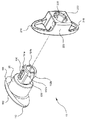
[0029]本発明の棘突起間デバイス10には、(i)隣接する棘突起間に配置されるように適合されたシャフト120、および上方棘突起および下方棘突起の横方向の面に沿って配置されるように適合された遠位保持部材110を有する主ボディ部分100と、(ii)上方棘突起および下方棘突起の反対側の横方向の面に沿って配置されるように適合された近位保持部材200が含まれている。また、遠位保持部材110と近位保持部材200の間の主ボディ部分100のシャフト120の周囲にダンパーリング20を配置することも可能である。シャフト120の近位部分は、ダンパーリング20を嵌合させることができる凹所領域を遠位保持部材110とシャフト120の近位部分の間に画定するために、シャフト120の残りの部分より大きい直径を有していることが好ましい。例えば図1を参照されたい。近位保持部材200には、近位保持部材200を主ボディ部分100に対して回転させることができるよう、主ボディ部分100のシャフト120の近位部分を配置することができる中央管腔225を画定している中央部分220が含まれている。
[0029] The
[0030]遠位保持部材110には、遠位上部ウィング111および遠位下部ウィング112が含まれている。遠位上部ウィング111は、デバイス10が隣接する棘突起間の空間の中に適切に配置された場合に、ダンパーリング20の縦軸が矢状面に対して概ね直角をなすように上方棘突起の遠位面と係合するように適合されている。例えば図15を参照されたい。この位置では、遠位下部ウィング112は、下方棘突起の遠位面と係合するように適合されている。本明細書において示されているように、遠位保持部材110は、長軸がA1であり、また、短軸がA2である概ね楕円形の構成を有している。楕円形の構成であることが好ましいが、第1の方向に対して垂直の方向の寸法より小さい寸法を第1の方向に提供する限り、遠位保持部材110の形状には他の任意の幾何学形状を使用することができる。長軸A1に沿った遠位保持部材110の寸法は、隣接する棘突起が所望の間隔まで伸延した場合のそれらの間の距離より大きい。短軸A2に沿った遠位保持部材110の寸法は、隣接する棘突起が所望の間隔まで伸延した場合のそれらの間の距離に概ね等しいことが好ましい。
[0030] The
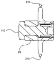
[0031]シャフト120の近位部分には、近位保持部材200の中央管腔225内に配置されている相補キー230と協同するスロット130が含まれている。2つのスロット130は、シャフト120の近位部分に沿って、約180度隔てて配置されていることが好ましい。これらのスロット130は、遠位保持部材110の短軸A2に対して実質的に平行の方向に延在している1本の線に沿ってそれらが整列するよう、180度隔てて整列していることがよりいっそう好ましい。また、シャフト120の近位端に隣接する周囲には、複数のラグが間隔を隔てて配置されている。これらのラグは、2つのセットのラグに分割され、個々のセットがスロット130の対の間に配置されるよう、約180度隔てて配置されていることが好ましい。図に示されているように、上部ラグ151aおよび151bは、遠位上部ウィング111と概ね整列しており、一方、下部ラグ152aおよび152bは、遠位下部ウィング112と概ね整列している。さらに、概ね平らな表面135が、シャフト120の近位部分に沿って、約180度隔てて配置されており、平らな表面135の各々は、スロット130の各々の間の1つのセットのラグに隣接して配置されている。言い換えると、平らな表面135は、長軸A1に対して実質的に平行の方向に延在している1本の線に沿って実質的に整列している。
[0031] The proximal portion of the
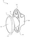
[0032]近位保持部材200には、近位上部ウィング210および近位下部ウィング215、ならびに中央部分220および中央管腔225が含まれている。本明細書において示されているように、近位保持部材200は、長軸がA3であり、また、短軸がA4である概ね楕円形の構成を有している。近位保持部材200は円周バーとして形成されている。しかしながら、近位保持部材200は、遠位保持部材110と同様、固体構成を有することも可能である。また、遠位保持部材110も、近位保持部材200と同様、円周バーとして形成することができる。近位保持部材200の構成の場合、楕円形の構成であることが好ましいが、第1の方向に対して垂直の方向の寸法より小さい寸法を第1の方向に提供する限り、近位保持部材200の形状には他の任意の幾何学形状を使用することができる。長軸A3に沿った近位保持部材200の寸法は、隣接する棘突起が所望の間隔まで伸延した場合のそれらの間の距離より大きい。長軸A3に沿った近位保持部材200の長さは、長軸A1に沿った遠位保持部材110の長さより長いことが好ましい。このより大きい寸法により、外科医に視覚キューが提供され、したがって外科医は、どちらの末端が近位部分で、どちらの末端が遠位部分であるかを速やかに決定することができる。さらに、デバイスの埋込みを容易にするためには、遠位保持部材110は比較的小さいことが好ましい。通常、棘突起の遠位面には、外科医がデバイスを操作するための広い空間は存在していない。
[0032]
[0033]キー230は、中央管腔225の中に、スロット130に対して相補受入れ方式で形成されている。2つのこのようなキー230は、中央管腔225の中に形成され、かつ短軸A4に沿って約180度隔てて配置されていることが好ましい。そうすることにより、遠位保持部材110の長軸A1が近位保持部材200の長軸A3に対して垂直の方向に延在すると、キー230を平らな表面135に整列させることができる。
[0033] The key 230 is formed in the
[0034]環状溝250は、中央管腔225の近位部分に沿ってその内部表面に沿って形成されている。環状溝250は、ラグ151a、151b、152aおよび152bのためのガイドとして作用するように形成されている。したがってラグ151a、151b、152aおよび152bは環状溝250の中に嵌合し、かつ近位保持部材200が主ボディ部分100に対して主ボディ部分100の縦軸の周りに回転すると、溝250に沿って移動することができる。ラグ151a、151b、152aおよび152bは、デバイス10をアセンブリしている間、主ボディ部分100がシャフト120の縦軸に沿った方向に移動して近位保持部材200と係合する際の環状溝250の中へのラグ151a、151b、152aおよび152bの移動を容易にするために、先細りになった近位端を有していることが好ましい。ラグ151a、151b、152aおよび152bは、平らな表面135に対して実質的に直角をなしている遠位端を有していることが好ましい。それにより、デバイス10がアセンブルされると、ラグ151a、151b、152aおよび152bを環状溝250から除去することが困難であることが保証され、また、主ボディ部分100を近位保持部材200から除去することができる可能性が最小化される。さらに、ラグ151aおよび151bは、キー230の幅より少なくともわずかに大きい距離だけ離れている。同様に、ラグ152aおよび152bも、キー230の幅より少なくともわずかに大きい距離だけ離れている。それにより、アセンブリの間、キー230が平らな表面135に隣接するよう、キー230をラグ151a、151b、152aおよび152bを通り越して移動させることができる。平らな表面135は、キー230を許容するための中央管腔225の壁と、中央管腔225内に嵌合するためのシャフト120の近位部分との間に十分な空間を提供している。
[0034] The
[0035]キー230およびスロット130は、キー230がスロット130の中にぴったりと嵌合するように構成されている。したがって、遠位保持部材110の長軸A1が、近位保持部材200の長軸A3と整列し、かつ長軸A3に対して平行である方向に延在するよう、主ボディ部分100が近位保持部材200に対して回転すると、キー230がスロット130の中に落下し、近位保持部材200を主ボディ部分100に対してロックする。これにより、デバイス10の構成がそのロックされた構成である場合、シャフト120およびダンパーリング20が、実質的に直角をなして矢状面を交差するように隣接する棘突起間に配置された状態で、デバイス10を隣接する棘突起間に配置することができることが保証され、遠位上部ウィング111および遠位下部ウィング112は、それぞれ上方棘突起および下方棘突起の遠位部分に沿って配置され、また、近位上部保持部材210および近位下部保持部材215は、それぞれ上方棘突起および下方棘突起の近位部分に沿って配置される。これにより、埋込み後におけるその位置からのデバイス10の移動が防止される。キーおよびスロットロック機構であることが好ましいが、ロック機構が(i)主ボディ部分100と近位保持部材200の間の相対回転を許容し、かつ(ii)遠位保持部材110の長軸A1が近位保持部材200の長軸A3の方向と同じ方向に延在するように、主ボディ部分100および近位保持部材200を互いに対してロックする限り、他のロック機構をデバイス10と共に使用することができる。
[0035]
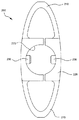
[0036]デバイス10の構成が例えば図3に示されているように埋込み構成である場合、近位保持部材200は、長軸A3が遠位保持部材110の長軸A1の配向に対して実質的に垂直になるように、つまり長軸A3が長軸A1の方向に対して実質的に垂直の方向に延在するように配向される。デバイス10の構成が例えば図5に示されているようにそのロックされた最終構成である場合、近位保持部材200の長軸A3は、遠位保持部材110の長軸A1と実質的に整列した方向に延在し、つまり長軸A3は、長軸A1の方向に対して実質的に平行の方向に延在する。キー230およびスロット130のこの構造により、初期埋込み位置と最終ロック位置との間で、主ボディ部分100を近位保持部材200に対して時計方向または反時計方向のいずれかに約90度回転させることができる。
[0036] When the configuration of the
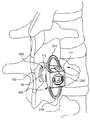
[0037]棘突起間靭帯は、通常、図には示されていないが、単純な解剖刀、電気外科デバイス、等々などの切断器具を使用して切開され、デバイス10の遠位部分を通過させることができる適切な大きさの開口が棘突起間靭帯中に生成される。図11を参照されたい。これにより、横方向手法を使用して、隣接する棘突起間の空間にデバイス10を埋め込むことができる。ほとんどの場合、最初に、図には示されていないが伸延ツールを使用して、隣接する棘突起間の空間を伸延させ、追加空間および患者に対する疼痛緩和を提供する必要がある。伸延が十分であることを内科医が確認すると、隣接する棘突起間の空間にデバイス10を配置することができる。デバイス10は、異なる量の伸延/隣接する棘突起間に必要な異なる広さの空間に適応するために、異なる大きさにすることができる。
[0037] The interspinous ligament is typically not shown in the figure, but is opened using a cutting instrument such as a simple dissecting knife, electrosurgical device, etc., and passed through the distal portion of
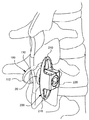
[0038]デバイス10の構成が上で説明した埋込み構成である場合、遠位保持部材110は、棘突起間靭帯中に形成された開口を介して挿入される。図12を参照されたい。遠位保持部材110は、その長軸A1が軸平面に対して概ね平行になり、かつ短軸A2が矢状面および冠状平面に対して概ね平行になるように配向される。この配向では、長軸A1は、矢状面および冠状平面に対して平行でも、垂直でもない。図12を参照されたい。この配向では、隣接する棘突起間の空間を通るデバイス10の移動が、短軸A2に沿った遠位保持部材110の寸法によって妨害されることはない。したがって遠位保持部材110は、周囲の組織に対する最小の破壊で、隣接する棘突起間の空間を通過することができる。重要なことには、棘上靭帯は、手順の間、妨害されない状態を維持する。デバイス10を適切に配置するためには、場合によっては、長軸A1が矢状面および冠状平面に対して平行でも、垂直でもない状態で、隣接する棘突起の間の空間を最初に遠位保持部材の前縁に通過させなければならない。遠位保持部材110の前縁が棘突起間靭帯中に形成された空間を通過すると、インプラント10の縦軸に対して垂直の軸の周りにデバイス10を回転させることができ、したがってインプラント10の縦軸は、冠状平面および軸平面に対して平行になり、また、矢状面に対して垂直になる。図12と図13を比較されたい。また、これにより、近位保持部材200が、隣接する上方棘突起および下方棘突起の近位面に沿って配置され、長軸A3は、矢状面および冠状平面に対して概ね平行になり、また、軸平面に対して概ね垂直になる。当然、所定の位置に適切に配置するためには、手順の間、遠位保持部材110の配向を調整することができなければならない。例えば、遠位保持部材110は、埋込み手順の一部またはすべての間、(i)デバイス10の縦軸の周り、(ii)その長軸の周り、および/または(iii)その短軸の周りに回転させることができなければならない。デバイス10が配置される身体の解剖学的構造の個々の特性のため、場合によってはこれらの操作が必要である。
[0038] When the configuration of
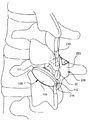
[0039]図13および14に示されているように、遠位保持部材110が、隣接する棘突起の遠位面に隣接すると、遠位保持部材110を近位保持部材200に対して、主ボディ部分100の縦軸の周りに回転させることができる。遠位保持部材110は、時計方向または反時計方向のいずれかに回転させることができる。この回転により、近位保持部材200の長軸A3および遠位保持部材110の長軸A1が、それらが同じ方向に延在し、したがって互いに概ね平行で、かつ矢状面および冠状平面に対して概ね平行であり、また、軸平面に対して概ね垂直になるように配向されるよう、遠位保持部材110が近位保持部材200に対してロックされる。上で指摘したように、遠位保持部材110および近位保持部材200の長軸A1およびA3は、それぞれ、隣接する棘突起間の距離より長い寸法を画定しており、近位保持部材200の寸法の方が大きいことが好ましい。当然、近位保持部材200と遠位保持部材110の間の距離は、隣接する棘突起の遠位面と隣接する棘突起の近位面との間の距離よりわずかに長くしなければならない。このようにして、デバイス10は、近位保持部材200および遠位保持部材110によって所定の位置に保持される。
[0039] As shown in FIGS. 13 and 14, when the
[0040]デバイス10は、例えば、チタン、チタン合金、外科用スチール、生体適合金属合金、ステンレス鋼、ニチノール、プラスチック、ポリエーテルエーテルケトン(PEEK)、炭素繊維、超高分子量(UHMW)ポリエチレンおよび他の生体適合重合材料などの様々な生体適合材料を使用して構築することができる。デバイス10の材料は、例えば、骨の圧縮強さと同様またはそれより強い圧縮強さを有することができる。一実施形態では、隣接する2つの棘突起の間に配置されるダンパーリング20は、棘突起の骨の弾性係数より大きい弾性係数を有する材料から形成されている。他の実施形態では、ダンパーリング20は、主ボディ部分100および近位保持部材200を形成するために使用される材料の弾性係数より大きい弾性係数を有する材料から形成されている。例えばダンパーリング20は、骨の弾性係数より大きい弾性係数を有することができ、一方、主ボディ部分100および近位保持部材100は、骨の弾性係数より小さい弾性係数を有している。脊柱が延長部分に移動する際の衝撃を和らげるためには、ダンパーリング20は、シリコーンなどの迎合材料で形成されることが好ましい。
[0040]
[0041]以上、本発明の様々な実施形態について説明したが、それらは単に一例として提供されたものにすぎず、本発明を限定するものではないことを理解されたい。棘突起間デバイスについての以上の説明は、余す所のないものであることを意図したものでも、あるいはデバイスの発明を限定することを意図したものでもない。当業者には多くの修正および変形形態が明らかであろう。本発明の範囲は、以下の特許請求の範囲およびそれらの等価物によって定義されるものとする。 [0041] While various embodiments of the invention have been described above, it should be understood that they are provided by way of example only and do not limit the invention. The above description of an interspinous process device is not intended to be exhaustive or to limit the invention of the device. Many modifications and variations will be apparent to the practitioner skilled in the art. The scope of the present invention is to be defined by the following claims and their equivalents.
10 棘突起間デバイス
20 ダンパーリング
100 主ボディ部分
110 遠位保持部材
111 遠位上部ウィング
112 遠位下部ウィング
120 シャフト
130 スロット
151a、151b 上部ラグ
152a、152b 下部ラグ
200 近位保持部材
210 近位上部ウィング
215 近位下部ウィング
220 中央部分
225 中央管腔
230 相補キー
250 環状溝
DESCRIPTION OF
Claims (20)
第2の保持部材を有し、前記第1の保持部材に対して第1の位置と第2の位置の間で回転させることができる主ボディ部分と
を備えたデバイス。 A first holding member;
A device comprising a main body portion having a second holding member and capable of rotating between a first position and a second position relative to the first holding member.
遠位保持部材、ならびに前記遠位保持部材から近位方向に延在している近位部分および遠位部分を有するシャフトを有する主ボディ部分であって、前記近位部分が前記中央管腔の中に配置された主ボディ部分と、
前記中央管腔の中に配置された少なくとも1つのキーと
を備え、前記シャフトの前記近位部分が前記少なくとも1つのキーと係合するように適合された少なくとも1つのスロットを画定しているデバイス。 A proximal retention member defining a central lumen therein;
A main body portion having a distal retention member and a shaft having a proximal portion and a distal portion extending proximally from the distal retention member, the proximal portion of the central lumen A main body part arranged inside,
At least one key disposed in the central lumen, wherein the proximal portion of the shaft defines at least one slot adapted to engage the at least one key .
前記上方棘突起の近位面および前記隣接する下方棘突起の近位面に隣接して近位保持部材を配向するステップと、
前記遠位保持部材を前記近位保持部材に対して、第1の位置と第2の位置の間で回転させるステップと、
前記遠位保持部材を前記近位保持部材に対してロックするステップであって、前記近位保持部材の長軸および前記遠位保持部材の長軸が、互いに実質的に平行であり、かつ矢状面および冠状平面に対して実質的に平行である方向に延在するステップと
を含む医療デバイスを埋め込む方法。 Inserting the distal retaining member through the space between the spinous processes such that the distal retaining member is adjacent the distal surface of the upper spinous process and the distal surface of the adjacent lower spinous process;
Orienting a proximal retention member adjacent the proximal surface of the upper spinous process and the proximal surface of the adjacent lower spinous process;
Rotating the distal holding member relative to the proximal holding member between a first position and a second position;
Locking the distal retaining member relative to the proximal retaining member, wherein the longitudinal axis of the proximal retaining member and the longitudinal axis of the distal retaining member are substantially parallel to each other and an arrow Extending in a direction substantially parallel to the coronal plane and the coronal plane.
Applications Claiming Priority (1)
| Application Number | Priority Date | Filing Date | Title |
|---|---|---|---|
| US12/607,917 US8771317B2 (en) | 2009-10-28 | 2009-10-28 | Interspinous process implant and method of implantation |
Publications (2)
| Publication Number | Publication Date |
|---|---|
| JP2011092712A true JP2011092712A (en) | 2011-05-12 |
| JP2011092712A5 JP2011092712A5 (en) | 2013-10-10 |
Family
ID=43245001
Family Applications (1)
| Application Number | Title | Priority Date | Filing Date |
|---|---|---|---|
| JP2010239486A Pending JP2011092712A (en) | 2009-10-28 | 2010-10-26 | Interspinous process implant and method of implantation |
Country Status (3)
| Country | Link |
|---|---|
| US (1) | US8771317B2 (en) |
| EP (1) | EP2316362A1 (en) |
| JP (1) | JP2011092712A (en) |
Cited By (3)
| Publication number | Priority date | Publication date | Assignee | Title |
|---|---|---|---|---|
| JP2012217826A (en) * | 2011-04-06 | 2012-11-12 | Chang-Hwa You | Spinous process spacer |
| KR20180093292A (en) | 2017-02-13 | 2018-08-22 | (주)시지바이오 | Implant for bone substitute |
| KR20180122134A (en) | 2017-05-02 | 2018-11-12 | (주)시지바이오 | Bone fusion member and interspinous implant using the same |
Families Citing this family (8)
| Publication number | Priority date | Publication date | Assignee | Title |
|---|---|---|---|---|
| WO2008106140A2 (en) | 2007-02-26 | 2008-09-04 | Abdou M Samy | Spinal stabilization systems and methods of use |
| US8945184B2 (en) * | 2009-03-13 | 2015-02-03 | Spinal Simplicity Llc. | Interspinous process implant and fusion cage spacer |
| US8262697B2 (en) * | 2010-01-14 | 2012-09-11 | X-Spine Systems, Inc. | Modular interspinous fixation system and method |
| US20120215262A1 (en) * | 2011-02-16 | 2012-08-23 | Interventional Spine, Inc. | Spinous process spacer and implantation procedure |
| US20120323276A1 (en) | 2011-06-17 | 2012-12-20 | Bryan Okamoto | Expandable interspinous device |
| US9149306B2 (en) | 2011-06-21 | 2015-10-06 | Seaspine, Inc. | Spinous process device |
| AU2013249305B2 (en) | 2012-04-17 | 2017-05-11 | Aurora Spine, Llc | A dynamic and non-dynamic interspinous fusion implant and bone growth stimulation system |
| WO2016137983A1 (en) | 2015-02-24 | 2016-09-01 | X-Spine Systems, Inc. | Modular interspinous fixation system with threaded component |
Citations (7)
| Publication number | Priority date | Publication date | Assignee | Title |
|---|---|---|---|---|
| JP2005525907A (en) * | 2002-05-17 | 2005-09-02 | エスディージーアイ・ホールディングス・インコーポレーテッド | Device for fixing spinal processes |
| JP2007514478A (en) * | 2003-12-02 | 2007-06-07 | セント フランシス メディカル テクノロジーズ インコーポレイテッド | Bioabsorbable intervertebral or replacement implants for use in the treatment of intervertebral discs and procedures thereof |
| US20080177306A1 (en) * | 2004-10-25 | 2008-07-24 | Lanx, Inc. | Spinal implants and methods |
| JP2008529737A (en) * | 2005-02-17 | 2008-08-07 | カイフォン インコーポレイテッド | Percutaneous spinal implant and method |
| JP2008539819A (en) * | 2005-04-29 | 2008-11-20 | ウォーソー・オーソペディック・インコーポレーテッド | Spinous process stabilization device and method |
| JP2009136440A (en) * | 2007-12-05 | 2009-06-25 | Kobe Univ | Fixation tool of adjacent spines of cervical vertebra |
| JP2010515528A (en) * | 2007-01-11 | 2010-05-13 | ランクス インコーポレイテッド | Spinous process implants and related methods |
Family Cites Families (285)
| Publication number | Priority date | Publication date | Assignee | Title |
|---|---|---|---|---|
| US624969A (en) | 1899-05-16 | Peter peterson | ||
| US1153797A (en) | 1915-04-29 | 1915-09-14 | Jules Emile Kegreisz | Expansion-anchor. |
| US1516347A (en) | 1923-08-30 | 1924-11-18 | Pataky Anton | Coupling pin |
| US2077804A (en) | 1936-05-19 | 1937-04-20 | Morrison Gordon Monroe | Device for treating fractures of the neck of the femur |
| US2299308A (en) | 1941-08-15 | 1942-10-20 | Russell A Creighton | Self-locking spike |
| US2485531A (en) | 1948-01-13 | 1949-10-18 | Dzus William | Surgical toggle bolt |
| US2607370A (en) | 1948-07-13 | 1952-08-19 | Oscar F Anderson | Pipe plug |
| US2685877A (en) | 1952-03-20 | 1954-08-10 | Dobelle Martin | Femoral head prosthesis |
| US2677369A (en) | 1952-03-26 | 1954-05-04 | Fred L Knowles | Apparatus for treatment of the spinal column |
| US3065659A (en) | 1959-09-28 | 1962-11-27 | Superior Concrete Accessories | Expansion bolt |
| US3426364A (en) | 1966-08-25 | 1969-02-11 | Colorado State Univ Research F | Prosthetic appliance for replacing one or more natural vertebrae |
| US3648691A (en) | 1970-02-24 | 1972-03-14 | Univ Colorado State Res Found | Method of applying vertebral appliance |
| DE2112139B2 (en) | 1971-03-13 | 1973-02-01 | Fischer, Artur, 7241 Tumhngen | SLEEVE-SHAPED CONNECTOR FOR COMPRESSION OSTEOSYNTHESIS IN TUBE BONE Fractures |
| US4011602A (en) | 1975-10-06 | 1977-03-15 | Battelle Memorial Institute | Porous expandable device for attachment to bone tissue |
| US4704057A (en) | 1976-09-15 | 1987-11-03 | Mechanical Plastics Corp. | Fastening element |
| PL114098B1 (en) | 1978-04-14 | 1981-01-31 | Wyzsza Szkola Inzynierska | Apparatus for correcting spinal curvature |
| US4274324A (en) | 1978-04-18 | 1981-06-23 | Giannuzzi Louis | Hollow wall screw anchor |
| CH628803A5 (en) | 1978-05-12 | 1982-03-31 | Sulzer Ag | Implant insertable between adjacent vertebrae |
| US4237875A (en) | 1979-02-23 | 1980-12-09 | Towmotor Corporation | Dynamic intramedullary compression nailing |
| US4289123A (en) | 1980-03-31 | 1981-09-15 | Dunn Harold K | Orthopedic appliance |
| GB2083754B (en) | 1980-09-15 | 1984-04-26 | Rezaian Seyed Mahmoud | Spinal fixator |
| SU988281A1 (en) | 1981-06-26 | 1983-01-15 | За витель | Vertical column fixing device |
| US4646998A (en) | 1981-11-20 | 1987-03-03 | Clairson International Corporation | Wall-mounted shelf support clip |
| US4519100A (en) | 1982-09-30 | 1985-05-28 | Orthopedic Equipment Co. Inc. | Distal locking intramedullary nail |
| US4822226A (en) | 1983-08-08 | 1989-04-18 | Kennedy Arvest G | Wing nut retainer and extractor |
| US4554914A (en) | 1983-10-04 | 1985-11-26 | Kapp John P | Prosthetic vertebral body |
| US4553273A (en) | 1983-11-23 | 1985-11-19 | Henry Ford Hospital | Vertebral body prosthesis and spine stabilizing method |
| GB8333442D0 (en) | 1983-12-15 | 1984-01-25 | Showell A W Sugicraft Ltd | Devices for spinal fixation |
| US4611582A (en) | 1983-12-27 | 1986-09-16 | Wisconsin Alumni Research Foundation | Vertebral clamp |
| US4604995A (en) | 1984-03-30 | 1986-08-12 | Stephens David C | Spinal stabilizer |
| US4573454A (en) | 1984-05-17 | 1986-03-04 | Hoffman Gregory A | Spinal fixation apparatus |
| FR2575059B1 (en) | 1984-12-21 | 1988-11-10 | Daher Youssef | SHORING DEVICE FOR USE IN A VERTEBRAL PROSTHESIS |
| US4632101A (en) | 1985-01-31 | 1986-12-30 | Yosef Freedland | Orthopedic fastener |
| US4636217A (en) | 1985-04-23 | 1987-01-13 | Regents Of The University Of Minnesota | Anterior spinal implant |
| US4599086A (en) | 1985-06-07 | 1986-07-08 | Doty James R | Spine stabilization device and method |
| SE458417B (en) | 1985-08-15 | 1989-04-03 | Sven Olerud | FIXING INSTRUMENTS PROVIDED FOR USE IN SPINE OPERATIONS |
| US4662808A (en) | 1985-10-02 | 1987-05-05 | Lee-Rowan Company | Wall anchor |
| US4931055A (en) | 1986-05-30 | 1990-06-05 | John Bumpus | Distraction rods |
| GB8620937D0 (en) | 1986-08-29 | 1986-10-08 | Shepperd J A N | Spinal implant |
| US4787378A (en) | 1986-09-08 | 1988-11-29 | Sodhi Jitendra S | Self-retaining nail for fracture of neck of femur |
| US4969887A (en) | 1986-09-08 | 1990-11-13 | Sodhi Jitendra S | Self-retaining nail kit for repairing a fractured neck of femur |
| CA1283501C (en) | 1987-02-12 | 1991-04-30 | Thomas P. Hedman | Artificial spinal disc |
| SU1484348A1 (en) | 1987-03-04 | 1989-06-07 | Белорусский научно-исследовательский институт травматологии и ортопедии | Spinal column fixing device |
| FR2623085B1 (en) | 1987-11-16 | 1992-08-14 | Breard Francis | SURGICAL IMPLANT TO LIMIT THE RELATIVE MOVEMENT OF VERTEBRES |
| FR2625097B1 (en) | 1987-12-23 | 1990-05-18 | Cote Sarl | INTER-SPINOUS PROSTHESIS COMPOSED OF SEMI-ELASTIC MATERIAL COMPRISING A TRANSFILING EYE AT ITS END AND INTER-SPINOUS PADS |
| US5609635A (en) | 1988-06-28 | 1997-03-11 | Michelson; Gary K. | Lordotic interbody spinal fusion implants |
| US4892545A (en) | 1988-07-14 | 1990-01-09 | Ohio Medical Instrument Company, Inc. | Vertebral lock |
| IT215084Z2 (en) | 1988-08-03 | 1990-07-30 | Torino A | VARIABLE EXCURSION CAMBRA |
| US4834600A (en) | 1988-08-25 | 1989-05-30 | Lemke Stuart H | Fastener assembly |
| GB8825909D0 (en) | 1988-11-04 | 1988-12-07 | Showell A W Sugicraft Ltd | Pedicle engaging means |
| US5201734A (en) | 1988-12-21 | 1993-04-13 | Zimmer, Inc. | Spinal locking sleeve assembly |
| US4886405A (en) | 1989-01-27 | 1989-12-12 | Blomberg Ingvar M | Wall mounting device |
| FR2642645B1 (en) | 1989-02-03 | 1992-08-14 | Breard Francis | FLEXIBLE INTERVERTEBRAL STABILIZER AND METHOD AND APPARATUS FOR CONTROLLING ITS VOLTAGE BEFORE PLACEMENT ON THE RACHIS |
| US5098433A (en) | 1989-04-12 | 1992-03-24 | Yosef Freedland | Winged compression bolt orthopedic fastener |
| DE3922044A1 (en) | 1989-07-05 | 1991-02-07 | Richter Turtur Matthias Dr | Treatment of fractured vertebra - by instrument which avoids any force on intact adjacent to vertebrae |
| US4932975A (en) | 1989-10-16 | 1990-06-12 | Vanderbilt University | Vertebral prosthesis |
| US5059193A (en) | 1989-11-20 | 1991-10-22 | Spine-Tech, Inc. | Expandable spinal implant and surgical method |
| US5454365A (en) | 1990-11-05 | 1995-10-03 | Bonutti; Peter M. | Mechanically expandable arthroscopic retractors |
| US5345927A (en) | 1990-03-02 | 1994-09-13 | Bonutti Peter M | Arthroscopic retractors |
| DE4012622C1 (en) | 1990-04-20 | 1991-07-18 | Eska Medical Luebeck Medizintechnik Gmbh & Co, 2400 Luebeck, De | Two-part metal vertebra implant - has parts locked by two toothed racks, pre-stressed by elastic cushion between both implant parts |
| US5047055A (en) | 1990-12-21 | 1991-09-10 | Pfizer Hospital Products Group, Inc. | Hydrogel intervertebral disc nucleus |
| JP3390431B2 (en) | 1991-02-22 | 2003-03-24 | マドハヴァン、ピシャロディ | Centrally expandable disc implant and method |
| US5390683A (en) | 1991-02-22 | 1995-02-21 | Pisharodi; Madhavan | Spinal implantation methods utilizing a middle expandable implant |
| US5171278A (en) | 1991-02-22 | 1992-12-15 | Madhavan Pisharodi | Middle expandable intervertebral disk implants |
| DE4128332A1 (en) | 1991-08-27 | 1993-03-04 | Man Ceramics Gmbh | SPINE BONE REPLACEMENT |
| US5290312A (en) | 1991-09-03 | 1994-03-01 | Alphatec | Artificial vertebral body |
| FR2681525A1 (en) | 1991-09-19 | 1993-03-26 | Medical Op | Device for flexible or semi-rigid stabilisation of the spine, in particular of the human spine, by a posterior route |
| CH686610A5 (en) | 1991-10-18 | 1996-05-15 | Pina Vertriebs Ag | Compression implant. |
| DE4208116C2 (en) | 1992-03-13 | 1995-08-03 | Link Waldemar Gmbh Co | Intervertebral disc prosthesis |
| US5312405A (en) | 1992-07-06 | 1994-05-17 | Zimmer, Inc. | Spinal rod coupler |
| FR2693364B1 (en) | 1992-07-07 | 1995-06-30 | Erpios Snc | INTERVERTEBRAL PROSTHESIS FOR STABILIZING ROTATORY AND FLEXIBLE-EXTENSION CONSTRAINTS. |
| FR2695026B1 (en) | 1992-08-25 | 1994-10-28 | Alexandre Worcel | Device for maintaining compression of a fractured bone. |
| DE9213656U1 (en) | 1992-10-09 | 1992-12-03 | Angiomed Ag, 7500 Karlsruhe, De | |
| US5562735A (en) | 1992-11-09 | 1996-10-08 | Hospital For Joint Diseases | Spinal stabilization system and improved method |
| US5702395A (en) | 1992-11-10 | 1997-12-30 | Sofamor S.N.C. | Spine osteosynthesis instrumentation for an anterior approach |
| ATE206602T1 (en) | 1992-11-12 | 2001-10-15 | Neville Alleyne | DEVICE FOR PROTECTING THE HEART |
| US5306275A (en) | 1992-12-31 | 1994-04-26 | Bryan Donald W | Lumbar spine fixation apparatus and method |
| US5527314A (en) | 1993-01-04 | 1996-06-18 | Danek Medical, Inc. | Spinal fixation system |
| US5540703A (en) | 1993-01-06 | 1996-07-30 | Smith & Nephew Richards Inc. | Knotted cable attachment apparatus formed of braided polymeric fibers |
| US5496318A (en) | 1993-01-08 | 1996-03-05 | Advanced Spine Fixation Systems, Inc. | Interspinous segmental spine fixation device |
| FR2700941A1 (en) | 1993-02-03 | 1994-08-05 | Felman Daniel | Monobloc interspinal intervertebral fixation implant |
| US5415661A (en) | 1993-03-24 | 1995-05-16 | University Of Miami | Implantable spinal assist device |
| FR2703239B1 (en) | 1993-03-30 | 1995-06-02 | Brio Bio Rhone Implant Medical | Clip for interspinous prosthesis. |
| EP0621020A1 (en) | 1993-04-21 | 1994-10-26 | SULZER Medizinaltechnik AG | Intervertebral prosthesis and method of implanting such a prosthesis |
| FR2707864B1 (en) | 1993-07-23 | 1996-07-19 | Jean Taylor | Surgical forceps for tensioning an osteosynthesis ligament. |
| US5360430A (en) | 1993-07-29 | 1994-11-01 | Lin Chih I | Intervertebral locking device |
| US5458641A (en) | 1993-09-08 | 1995-10-17 | Ramirez Jimenez; Juan J. | Vertebral body prosthesis |
| US5439463A (en) | 1993-11-12 | 1995-08-08 | Lin; Chih-I | Spinal clamping device |
| US5454812A (en) | 1993-11-12 | 1995-10-03 | Lin; Chih-I | Spinal clamping device having multiple distance adjusting strands |
| US5403316A (en) | 1993-12-02 | 1995-04-04 | Danek Medical, Inc. | Triangular construct for spinal fixation |
| FR2715293B1 (en) | 1994-01-26 | 1996-03-22 | Biomat | Vertebral interbody fusion cage. |
| US5474561A (en) * | 1994-02-01 | 1995-12-12 | Yao; Meei-Huei | All positional and universal guiding device for interlocking intramedullary nail |
| US5653762A (en) | 1994-03-18 | 1997-08-05 | Pisharodi; Madhavan | Method of stabilizing adjacent vertebrae with rotating, lockable, middle-expanded intervertebral disk stabilizer |
| FR2717675B1 (en) | 1994-03-24 | 1996-05-03 | Jean Taylor | Interspinous wedge. |
| FR2719763B1 (en) | 1994-05-11 | 1996-09-27 | Jean Taylor | Vertebral implant. |
| FR2721501B1 (en) | 1994-06-24 | 1996-08-23 | Fairant Paulette | Prostheses of the vertebral articular facets. |
| DE4423257C2 (en) | 1994-07-02 | 2001-07-12 | Ulrich Heinrich | Implant to be inserted between the vertebral body of the spine as a placeholder |
| FR2722087A1 (en) | 1994-07-08 | 1996-01-12 | Cahlik Marc Andre | Surgical implant for limiting relative movement of vertebrae |
| FR2722088B1 (en) | 1994-07-08 | 1998-01-23 | Cahlik Marc Andre | SURGICAL IMPLANT FOR STABILIZING THE INTERVERTEBRAL SPACE |
| FR2722980B1 (en) | 1994-07-26 | 1996-09-27 | Samani Jacques | INTERTEPINOUS VERTEBRAL IMPLANT |
| DE9413471U1 (en) | 1994-08-20 | 1995-12-21 | Schaefer Micomed Gmbh | Ventral intervertebral implant |
| EP0700671B1 (en) | 1994-09-08 | 2001-08-08 | Stryker Technologies Corporation | Hydrogel intervertebral disc nucleus |
| FR2724554B1 (en) | 1994-09-16 | 1997-01-24 | Voydeville Gilles | DEVICE FOR FIXING A LIGAMENT PROSTHESIS |
| DE69532856T2 (en) | 1994-10-17 | 2005-04-21 | Raymedica Inc | Spinal disc-GRAFT |
| FR2725892A1 (en) | 1994-10-21 | 1996-04-26 | Felman Daniel | Vertebral implant insertion process using shape memory material |
| FR2728159B1 (en) | 1994-12-16 | 1997-06-27 | Tornier Sa | ELASTIC DISC PROSTHESIS |
| FR2729556B1 (en) | 1995-01-23 | 1998-10-16 | Sofamor | SPINAL OSTEOSYNTHESIS DEVICE WITH MEDIAN HOOK AND VERTEBRAL ANCHOR SUPPORT |
| US5665122A (en) | 1995-01-31 | 1997-09-09 | Kambin; Parviz | Expandable intervertebral cage and surgical method |
| FR2730156B1 (en) | 1995-02-03 | 1997-04-30 | Textile Hi Tec | INTER SPINOUS HOLD |
| FR2730158B1 (en) | 1995-02-06 | 1999-11-26 | Jbs Sa | DEVICE FOR MAINTAINING A NORMAL SPACING BETWEEN VERTEBRES AND FOR THE REPLACEMENT OF MISSING VERTEBRES |
| US5658335A (en) | 1995-03-09 | 1997-08-19 | Cohort Medical Products Group, Inc. | Spinal fixator |
| FR2731643A1 (en) | 1995-03-16 | 1996-09-20 | Jbs Sa | Angular screwdriver for access of awkwardly placed screws for use in surgery |
| US5630816A (en) | 1995-05-01 | 1997-05-20 | Kambin; Parviz | Double barrel spinal fixation system and method |
| WO1996039090A1 (en) | 1995-06-06 | 1996-12-12 | Sdgi Holdings, Inc. | Device for linking adjacent rods in spinal instrumentation |
| US5690649A (en) | 1995-12-05 | 1997-11-25 | Li Medical Technologies, Inc. | Anchor and anchor installation tool and method |
| US5653763A (en) | 1996-03-29 | 1997-08-05 | Fastenetix, L.L.C. | Intervertebral space shape conforming cage device |
| WO1997048352A1 (en) | 1996-06-18 | 1997-12-24 | Mehran Kasra | Bone prosthesis fixation device and methods of using same |
| US5746762A (en) | 1996-06-24 | 1998-05-05 | Bass; Lawrence S. | Device and method for surgical flap dissection |
| US5702455A (en) | 1996-07-03 | 1997-12-30 | Saggar; Rahul | Expandable prosthesis for spinal fusion |
| US5849004A (en) | 1996-07-17 | 1998-12-15 | Bramlet; Dale G. | Surgical anchor |
| US5716416A (en) | 1996-09-10 | 1998-02-10 | Lin; Chih-I | Artificial intervertebral disk and method for implanting the same |
| US5810815A (en) | 1996-09-20 | 1998-09-22 | Morales; Jose A. | Surgical apparatus for use in the treatment of spinal deformities |
| US6190414B1 (en) | 1996-10-31 | 2001-02-20 | Surgical Dynamics Inc. | Apparatus for fusion of adjacent bone structures |
| US5893850A (en) | 1996-11-12 | 1999-04-13 | Cachia; Victor V. | Bone fixation device |
| DE19652608C1 (en) | 1996-12-18 | 1998-08-27 | Eska Implants Gmbh & Co | Prophylaxis implant against fractures of osteoporotically affected bone segments |
| US20050245937A1 (en) | 2004-04-28 | 2005-11-03 | St. Francis Medical Technologies, Inc. | System and method for insertion of an interspinous process implant that is rotatable in order to retain the implant relative to the spinous processes |
| US7306628B2 (en) | 2002-10-29 | 2007-12-11 | St. Francis Medical Technologies | Interspinous process apparatus and method with a selectably expandable spacer |
| US6451019B1 (en) | 1998-10-20 | 2002-09-17 | St. Francis Medical Technologies, Inc. | Supplemental spine fixation device and method |
| US7959652B2 (en) | 2005-04-18 | 2011-06-14 | Kyphon Sarl | Interspinous process implant having deployable wings and method of implantation |
| US5860977A (en) | 1997-01-02 | 1999-01-19 | Saint Francis Medical Technologies, Llc | Spine distraction implant and method |
| US6068630A (en) | 1997-01-02 | 2000-05-30 | St. Francis Medical Technologies, Inc. | Spine distraction implant |
| US7201751B2 (en) | 1997-01-02 | 2007-04-10 | St. Francis Medical Technologies, Inc. | Supplemental spine fixation device |
| US7101375B2 (en) | 1997-01-02 | 2006-09-05 | St. Francis Medical Technologies, Inc. | Spine distraction implant |
| US20020143331A1 (en) | 1998-10-20 | 2002-10-03 | Zucherman James F. | Inter-spinous process implant and method with deformable spacer |
| US5836948A (en) | 1997-01-02 | 1998-11-17 | Saint Francis Medical Technologies, Llc | Spine distraction implant and method |
| US6695842B2 (en) | 1997-10-27 | 2004-02-24 | St. Francis Medical Technologies, Inc. | Interspinous process distraction system and method with positionable wing and method |
| US5725341A (en) | 1997-01-08 | 1998-03-10 | Hofmeister; Oskar | Self fusing fastener |
| IL128261A0 (en) | 1999-01-27 | 1999-11-30 | Disc O Tech Medical Tech Ltd | Expandable element |
| CA2283190A1 (en) | 1997-03-07 | 1998-09-11 | Mordechay Beyar | Systems for percutaneous bone and spinal stabilization, fixation and repair |
| WO2001054598A1 (en) | 1998-03-06 | 2001-08-02 | Disc-O-Tech Medical Technologies, Ltd. | Expanding bone implants |
| US20070282443A1 (en) | 1997-03-07 | 2007-12-06 | Disc-O-Tech Medical Technologies Ltd. | Expandable element |
| US6022376A (en) | 1997-06-06 | 2000-02-08 | Raymedica, Inc. | Percutaneous prosthetic spinal disc nucleus and method of manufacture |
| EP1867293A2 (en) | 1997-10-27 | 2007-12-19 | St. Francis Medical Technologies, Inc. | Spine distraction implant |
| US5980523A (en) | 1998-01-08 | 1999-11-09 | Jackson; Roger | Transverse connectors for spinal rods |
| FR2774581B1 (en) | 1998-02-10 | 2000-08-11 | Dimso Sa | INTEREPINOUS STABILIZER TO BE ATTACHED TO SPINOUS APOPHYSIS OF TWO VERTEBRES |
| FR2775183B1 (en) | 1998-02-20 | 2000-08-04 | Jean Taylor | INTER-SPINOUS PROSTHESIS |
| DE19816782A1 (en) | 1998-04-16 | 1999-10-28 | Ulrich Gmbh & Co Kg | Implant for insertion between the vertebral body of the spine |
| DE19818143A1 (en) | 1998-04-23 | 1999-10-28 | Medinorm Ag | Device for connecting vertebrae of the spine |
| US6126689A (en) | 1998-06-15 | 2000-10-03 | Expanding Concepts, L.L.C. | Collapsible and expandable interbody fusion device |
| US6264658B1 (en) | 1998-07-06 | 2001-07-24 | Solco Surgical Instruments Co., Ltd. | Spine fixing apparatus |
| US6352537B1 (en) | 1998-09-17 | 2002-03-05 | Electro-Biology, Inc. | Method and apparatus for spinal fixation |
| US7029473B2 (en) | 1998-10-20 | 2006-04-18 | St. Francis Medical Technologies, Inc. | Deflectable spacer for use as an interspinous process implant and method |
| US6554833B2 (en) | 1998-10-26 | 2003-04-29 | Expanding Orthopedics, Inc. | Expandable orthopedic device |
| US6261289B1 (en) | 1998-10-26 | 2001-07-17 | Mark Levy | Expandable orthopedic device |
| ATE322868T1 (en) | 1998-10-30 | 2006-04-15 | Ian Ross Griggs | FIXATION DEVICE |
| BR9805340B1 (en) | 1998-12-14 | 2009-01-13 | variable expansion insert for spinal stabilization. | |
| US6520991B2 (en) | 1999-05-11 | 2003-02-18 | Donald R. Huene | Expandable implant for inter-vertebral stabilization, and a method of stabilizing vertebrae |
| US6214050B1 (en) | 1999-05-11 | 2001-04-10 | Donald R. Huene | Expandable implant for inter-bone stabilization and adapted to extrude osteogenic material, and a method of stabilizing bones while extruding osteogenic material |
| US6419704B1 (en) | 1999-10-08 | 2002-07-16 | Bret Ferree | Artificial intervertebral disc replacement methods and apparatus |
| US6770096B2 (en) | 1999-07-01 | 2004-08-03 | Spinevision S.A. | Interbody spinal stabilization cage and spinal stabilization method |
| JP4247519B2 (en) | 1999-08-18 | 2009-04-02 | イントリンジック セラピューティックス インコーポレイテッド | Apparatus and method for nucleus augmentation and retention |
| FR2799640B1 (en) | 1999-10-15 | 2002-01-25 | Spine Next Sa | IMPLANT INTERVETEBRAL |
| FR2799948B1 (en) | 1999-10-22 | 2002-03-29 | Transco Esquisse | CONNECTION BAR FOR ANCHORING AN INTER-THINNING PROSTHESIS |
| CA2391062C (en) | 1999-11-11 | 2008-01-08 | Synthes (U.S.A.) | Radially expandable intramedullary nail |
| US6293949B1 (en) | 2000-03-01 | 2001-09-25 | Sdgi Holdings, Inc. | Superelastic spinal stabilization system and method |
| US6336930B1 (en) | 2000-03-07 | 2002-01-08 | Zimmer, Inc. | Polymer filled bone plate |
| FR2806616B1 (en) | 2000-03-21 | 2003-04-11 | Cousin Biotech | INTERPINEUSE SHIM AND FASTENING DEVICE ON THE SACRUM |
| US6402750B1 (en) | 2000-04-04 | 2002-06-11 | Spinlabs, Llc | Devices and methods for the treatment of spinal disorders |
| US6645207B2 (en) | 2000-05-08 | 2003-11-11 | Robert A. Dixon | Method and apparatus for dynamized spinal stabilization |
| US6730123B1 (en) * | 2000-06-22 | 2004-05-04 | Proteus Vision, Llc | Adjustable intraocular lens |
| US6964667B2 (en) | 2000-06-23 | 2005-11-15 | Sdgi Holdings, Inc. | Formed in place fixation system with thermal acceleration |
| FR2811540B1 (en) | 2000-07-12 | 2003-04-25 | Spine Next Sa | IMPORTING INTERVERTEBRAL IMPLANT |
| EP1331906A2 (en) | 2000-10-25 | 2003-08-06 | SDGI Holdings, Inc. | Vertically expanding intervertebral body fusion device |
| US6582467B1 (en) | 2000-10-31 | 2003-06-24 | Vertelink Corporation | Expandable fusion cage |
| FR2816197B1 (en) | 2000-11-07 | 2003-01-10 | Jean Taylor | INTER-SPINABLE PROSTHESIS, TOOL AND PROCESS FOR PREPARING THE SAME |
| US6666891B2 (en) | 2000-11-13 | 2003-12-23 | Frank H. Boehm, Jr. | Device and method for lumbar interbody fusion |
| US6579319B2 (en) | 2000-11-29 | 2003-06-17 | Medicinelodge, Inc. | Facet joint replacement |
| US6743257B2 (en) | 2000-12-19 | 2004-06-01 | Cortek, Inc. | Dynamic implanted intervertebral spacer |
| FR2818530B1 (en) | 2000-12-22 | 2003-10-31 | Spine Next Sa | INTERVERTEBRAL IMPLANT WITH DEFORMABLE SHIM |
| GB0102141D0 (en) | 2001-01-27 | 2001-03-14 | Davies John B C | Improvements in or relating to expandable bone nails |
| US6364883B1 (en) | 2001-02-23 | 2002-04-02 | Albert N. Santilli | Spinous process clamp for spinal fusion and method of operation |
| FR2822051B1 (en) | 2001-03-13 | 2004-02-27 | Spine Next Sa | INTERVERTEBRAL IMPLANT WITH SELF-LOCKING ATTACHMENT |
| US6582433B2 (en) | 2001-04-09 | 2003-06-24 | St. Francis Medical Technologies, Inc. | Spine fixation device and method |
| US20030040746A1 (en) | 2001-07-20 | 2003-02-27 | Mitchell Margaret E. | Spinal stabilization system and method |
| US6375682B1 (en) | 2001-08-06 | 2002-04-23 | Lewis W. Fleischmann | Collapsible, rotatable and expandable spinal hydraulic prosthetic device |
| FR2828398B1 (en) | 2001-08-08 | 2003-09-19 | Jean Taylor | VERTEBRA STABILIZATION ASSEMBLY |
| WO2003015645A1 (en) | 2001-08-20 | 2003-02-27 | Synthes Ag Chur | Interspinal prosthesis |
| US20030114853A1 (en) | 2001-10-12 | 2003-06-19 | Ian Burgess | Polyaxial cross connector |
| FR2832917B1 (en) | 2001-11-30 | 2004-09-24 | Spine Next Sa | ELASTICALLY DEFORMABLE INTERVERTEBRAL IMPLANT |
| AU2002351368A1 (en) | 2001-12-13 | 2003-06-30 | Warsaw Orthopedic, Inc. | Instrumentation and method for delivering an implant into a vertebral space |
| WO2003057055A1 (en) | 2001-12-27 | 2003-07-17 | Osteotech Inc. | Orthopedic/neurosurgical system and method for securing vertebral bone facets |
| FR2835173B1 (en) | 2002-01-28 | 2004-11-05 | Biomet Merck France | INTERTEPINEOUS VERTEBRAL IMPLANT |
| US6733534B2 (en) | 2002-01-29 | 2004-05-11 | Sdgi Holdings, Inc. | System and method for spine spacing |
| US6923830B2 (en) | 2002-02-02 | 2005-08-02 | Gary K. Michelson | Spinal fusion implant having deployable bone engaging projections |
| JP3708883B2 (en) | 2002-02-08 | 2005-10-19 | 昭和医科工業株式会社 | Vertebral space retainer |
| EP1346708A1 (en) | 2002-03-20 | 2003-09-24 | A-Spine Holding Group Corp. | Three-hooked device for fixing spinal column |
| US20030220643A1 (en) | 2002-05-24 | 2003-11-27 | Ferree Bret A. | Devices to prevent spinal extension |
| FR2844179B1 (en) | 2002-09-10 | 2004-12-03 | Jean Taylor | POSTERIOR VERTEBRAL SUPPORT KIT |
| US7549999B2 (en) | 2003-05-22 | 2009-06-23 | Kyphon Sarl | Interspinous process distraction implant and method of implantation |
| US7833246B2 (en) | 2002-10-29 | 2010-11-16 | Kyphon SÀRL | Interspinous process and sacrum implant and method |
| US20060064165A1 (en) | 2004-09-23 | 2006-03-23 | St. Francis Medical Technologies, Inc. | Interspinous process implant including a binder and method of implantation |
| US7931674B2 (en) | 2005-03-21 | 2011-04-26 | Kyphon Sarl | Interspinous process implant having deployable wing and method of implantation |
| US6723126B1 (en) | 2002-11-01 | 2004-04-20 | Sdgi Holdings, Inc. | Laterally expandable cage |
| US6685742B1 (en) | 2002-11-12 | 2004-02-03 | Roger P. Jackson | Articulated anterior expandable spinal fusion cage system |
| WO2004047689A1 (en) | 2002-11-21 | 2004-06-10 | Sdgi Holdings, Inc. | Systems and techniques for intravertebral spinal stablization with expandable devices |
| JP2006510400A (en) | 2002-11-21 | 2006-03-30 | エスディージーアイ・ホールディングス・インコーポレーテッド | Systems and techniques for spinal stabilization between vertebral bodies using expandable devices |
| FR2850009B1 (en) | 2003-01-20 | 2005-12-23 | Spine Next Sa | TREATMENT ASSEMBLY FOR THE DEGENERATION OF AN INTERVERTEBRAL DISC |
| US7335203B2 (en) | 2003-02-12 | 2008-02-26 | Kyphon Inc. | System and method for immobilizing adjacent spinous processes |
| FR2851154B1 (en) | 2003-02-19 | 2006-07-07 | Sdgi Holding Inc | INTER-SPINOUS DEVICE FOR BRAKING THE MOVEMENTS OF TWO SUCCESSIVE VERTEBRATES, AND METHOD FOR MANUFACTURING THE SAME THEREOF |
| US7824444B2 (en) | 2003-03-20 | 2010-11-02 | Spineco, Inc. | Expandable spherical spinal implant |
| ITFI20030084A1 (en) | 2003-03-28 | 2004-09-29 | Cousin Biotech S A S | INTERLAMINARY VERTEBRAL PROSTHESIS |
| KR100582768B1 (en) | 2003-07-24 | 2006-05-23 | 최병관 | Insert complement for vertebra |
| CN2638760Y (en) | 2003-08-04 | 2004-09-08 | 邹德威 | Dilator for forming cavity in pyramid |
| US7377942B2 (en) | 2003-08-06 | 2008-05-27 | Warsaw Orthopedic, Inc. | Posterior elements motion restoring device |
| PL1675513T3 (en) | 2003-10-24 | 2013-09-30 | Cousin Biotech S A S | Inter-blade support |
| WO2005044152A1 (en) | 2003-11-07 | 2005-05-19 | Impliant Ltd. | Spinal prostheses |
| WO2005048856A1 (en) | 2003-11-10 | 2005-06-02 | Umc Utrecht Holding B.V. | Expandable implant for treating fractured and/or collapsed bone |
| US7217293B2 (en) | 2003-11-21 | 2007-05-15 | Warsaw Orthopedic, Inc. | Expandable spinal implant |
| US20050165398A1 (en) | 2004-01-26 | 2005-07-28 | Reiley Mark A. | Percutaneous spine distraction implant systems and methods |
| US7641664B2 (en) | 2004-02-12 | 2010-01-05 | Warsaw Orthopedic, Inc. | Surgical instrumentation and method for treatment of a spinal structure |
| US8636802B2 (en) | 2004-03-06 | 2014-01-28 | DePuy Synthes Products, LLC | Dynamized interspinal implant |
| US7458981B2 (en) | 2004-03-09 | 2008-12-02 | The Board Of Trustees Of The Leland Stanford Junior University | Spinal implant and method for restricting spinal flexion |
| US7763073B2 (en) | 2004-03-09 | 2010-07-27 | Depuy Spine, Inc. | Posterior process dynamic spacer |
| US7507241B2 (en) | 2004-04-05 | 2009-03-24 | Expanding Orthopedics Inc. | Expandable bone device |
| FR2870107B1 (en) | 2004-05-11 | 2007-07-27 | Spine Next Sa | SELF-LOCKING DEVICE FOR FIXING AN INTERVERTEBRAL IMPLANT |
| AU2005244312B2 (en) | 2004-05-17 | 2008-07-03 | Sang-Ho Lee | Spine insert |
| US7585316B2 (en) | 2004-05-21 | 2009-09-08 | Warsaw Orthopedic, Inc. | Interspinous spacer |
| FR2871366A1 (en) | 2004-06-09 | 2005-12-16 | Ceravic Soc Par Actions Simpli | PROSTHETIC EXPANSIBLE BONE IMPLANT |
| US7776091B2 (en) | 2004-06-30 | 2010-08-17 | Depuy Spine, Inc. | Adjustable posterior spinal column positioner |
| US20060015181A1 (en) | 2004-07-19 | 2006-01-19 | Biomet Merck France (50% Interest) | Interspinous vertebral implant |
| US7951153B2 (en) | 2004-10-05 | 2011-05-31 | Samy Abdou | Devices and methods for inter-vertebral orthopedic device placement |
| US20060085073A1 (en) | 2004-10-18 | 2006-04-20 | Kamshad Raiszadeh | Medical device systems for the spine |
| US8409282B2 (en) | 2004-10-20 | 2013-04-02 | Vertiflex, Inc. | Systems and methods for posterior dynamic stabilization of the spine |
| US8317864B2 (en) | 2004-10-20 | 2012-11-27 | The Board Of Trustees Of The Leland Stanford Junior University | Systems and methods for posterior dynamic stabilization of the spine |
| US8012207B2 (en) | 2004-10-20 | 2011-09-06 | Vertiflex, Inc. | Systems and methods for posterior dynamic stabilization of the spine |
| US9023084B2 (en) | 2004-10-20 | 2015-05-05 | The Board Of Trustees Of The Leland Stanford Junior University | Systems and methods for stabilizing the motion or adjusting the position of the spine |
| US8123807B2 (en) | 2004-10-20 | 2012-02-28 | Vertiflex, Inc. | Systems and methods for posterior dynamic stabilization of the spine |
| US8167944B2 (en) | 2004-10-20 | 2012-05-01 | The Board Of Trustees Of The Leland Stanford Junior University | Systems and methods for posterior dynamic stabilization of the spine |
| US7763074B2 (en) | 2004-10-20 | 2010-07-27 | The Board Of Trustees Of The Leland Stanford Junior University | Systems and methods for posterior dynamic stabilization of the spine |
| US8162985B2 (en) | 2004-10-20 | 2012-04-24 | The Board Of Trustees Of The Leland Stanford Junior University | Systems and methods for posterior dynamic stabilization of the spine |
| US20060089719A1 (en) | 2004-10-21 | 2006-04-27 | Trieu Hai H | In situ formation of intervertebral disc implants |
| CA2614133A1 (en) | 2004-10-25 | 2006-05-04 | Lanx, Llc | Interspinous distraction devices and associated methods of insertion |
| US7918875B2 (en) | 2004-10-25 | 2011-04-05 | Lanx, Inc. | Interspinous distraction devices and associated methods of insertion |
| US20060095136A1 (en) | 2004-11-03 | 2006-05-04 | Mcluen Design, Inc. | Bone fusion device |
| US20060106381A1 (en) | 2004-11-18 | 2006-05-18 | Ferree Bret A | Methods and apparatus for treating spinal stenosis |
| WO2006064356A1 (en) | 2004-12-16 | 2006-06-22 | Doellinger Horst | Implant for the treatment of lumbar spinal canal stenosis |
| DE102005005694A1 (en) | 2005-02-08 | 2006-08-17 | Henning Kloss | Spine vertebra support device for twpporting two sucessive vertebras, useful in implantation processes has two supoirts and two suppor holders |
| US8096994B2 (en) | 2005-02-17 | 2012-01-17 | Kyphon Sarl | Percutaneous spinal implants and methods |
| US7998174B2 (en) | 2005-02-17 | 2011-08-16 | Kyphon Sarl | Percutaneous spinal implants and methods |
| US8038698B2 (en) | 2005-02-17 | 2011-10-18 | Kphon Sarl | Percutaneous spinal implants and methods |
| US20070276493A1 (en) | 2005-02-17 | 2007-11-29 | Malandain Hugues F | Percutaneous spinal implants and methods |
| US20060195102A1 (en) | 2005-02-17 | 2006-08-31 | Malandain Hugues F | Apparatus and method for treatment of spinal conditions |
| US7611316B2 (en) | 2005-02-17 | 2009-11-03 | Illinois Tool Works Inc. | Heavy duty toggle bolt fastener for accommodating long screws and having properly positioned toggle nut component |
| US20060184248A1 (en) | 2005-02-17 | 2006-08-17 | Edidin Avram A | Percutaneous spinal implants and methods |
| US8007521B2 (en) | 2005-02-17 | 2011-08-30 | Kyphon Sarl | Percutaneous spinal implants and methods |
| US20060241757A1 (en) | 2005-03-31 | 2006-10-26 | Sdgi Holdings, Inc. | Intervertebral prosthetic device for spinal stabilization and method of manufacturing same |
| FR2884136B1 (en) | 2005-04-08 | 2008-02-22 | Spinevision Sa | INTERVERTEBRAL SURGICAL IMPLANT FORMING BALL |
| JP5345839B2 (en) | 2005-04-08 | 2013-11-20 | パラダイム・スパイン・リミテッド・ライアビリティ・カンパニー | Interspinous vertebrae and lumbosacral stabilization device and method of use |
| US7780709B2 (en) | 2005-04-12 | 2010-08-24 | Warsaw Orthopedic, Inc. | Implants and methods for inter-transverse process dynamic stabilization of a spinal motion segment |
| US7789898B2 (en) | 2005-04-15 | 2010-09-07 | Warsaw Orthopedic, Inc. | Transverse process/laminar spacer |
| US9237908B2 (en) | 2005-04-21 | 2016-01-19 | Spine Wave, Inc. | Dynamic stabilization system for the spine |
| US20060247623A1 (en) | 2005-04-29 | 2006-11-02 | Sdgi Holdings, Inc. | Local delivery of an active agent from an orthopedic implant |
| US7837688B2 (en) | 2005-06-13 | 2010-11-23 | Globus Medical | Spinous process spacer |
| US7383639B2 (en) | 2005-07-12 | 2008-06-10 | Medtronic Spine Llc | Measurement instrument for percutaneous surgery |
| US7753938B2 (en) | 2005-08-05 | 2010-07-13 | Synthes Usa, Llc | Apparatus for treating spinal stenosis |
| US20090036925A1 (en) | 2005-09-21 | 2009-02-05 | Sintea Biotech S.P.A. | Device, Kit and Method For Intervertebral Stabilization |
| WO2007052975A1 (en) | 2005-11-03 | 2007-05-10 | Dong-Kyu Chin | Fixing device for spinous process |
| US7998173B2 (en) | 2005-11-22 | 2011-08-16 | Richard Perkins | Adjustable spinous process spacer device and method of treating spinal stenosis |
| JP2009525060A (en) | 2005-12-06 | 2009-07-09 | グローバス メディカル インコーポレイティッド | Intervertebral joint prosthesis |
| US7837711B2 (en) * | 2006-01-27 | 2010-11-23 | Warsaw Orthopedic, Inc. | Artificial spinous process for the sacrum and methods of use |
| US20070191838A1 (en) | 2006-01-27 | 2007-08-16 | Sdgi Holdings, Inc. | Interspinous devices and methods of use |
| US20070233089A1 (en) | 2006-02-17 | 2007-10-04 | Endius, Inc. | Systems and methods for reducing adjacent level disc disease |
| US20070233068A1 (en) | 2006-02-22 | 2007-10-04 | Sdgi Holdings, Inc. | Intervertebral prosthetic assembly for spinal stabilization and method of implanting same |
| TW200738209A (en) * | 2006-04-07 | 2007-10-16 | Chung-Chun Yeh | Apparatus for holding open the vertebral spinous process |
| US8062337B2 (en) | 2006-05-04 | 2011-11-22 | Warsaw Orthopedic, Inc. | Expandable device for insertion between anatomical structures and a procedure utilizing same |
| US20070276369A1 (en) | 2006-05-26 | 2007-11-29 | Sdgi Holdings, Inc. | In vivo-customizable implant |
| US20080021457A1 (en) | 2006-07-05 | 2008-01-24 | Warsaw Orthopedic Inc. | Zygapophysial joint repair system |
| US7879104B2 (en) * | 2006-11-15 | 2011-02-01 | Warsaw Orthopedic, Inc. | Spinal implant system |
| US20080114455A1 (en) * | 2006-11-15 | 2008-05-15 | Warsaw Orthopedic, Inc. | Rotating Interspinous Process Devices and Methods of Use |
| US20080183218A1 (en) | 2007-01-31 | 2008-07-31 | Nuvasive, Inc. | System and Methods for Spinous Process Fusion |
| WO2008098054A2 (en) * | 2007-02-06 | 2008-08-14 | Pioneer Surgical Technology, Inc. | Intervertebral implant devices and methods for insertion thereof |
| US7799058B2 (en) | 2007-04-19 | 2010-09-21 | Zimmer Gmbh | Interspinous spacer |
| WO2009083276A1 (en) | 2008-01-03 | 2009-07-09 | Andrea Fontanella | Percutaneous interspinous process spacer |
| ITPI20080010A1 (en) | 2008-02-07 | 2009-08-08 | Giuseppe Calvosa | INTERSTEIN VERTEBRAL DISTRACTOR FOR PERCUTANEOUS INSERTION |
| TW200938157A (en) | 2008-03-11 | 2009-09-16 | Fong-Ying Chuang | Interspinous spine fixing device |
-
2009
- 2009-10-28 US US12/607,917 patent/US8771317B2/en active Active
-
2010
- 2010-10-26 JP JP2010239486A patent/JP2011092712A/en active Pending
- 2010-10-28 EP EP10189284A patent/EP2316362A1/en not_active Withdrawn
Patent Citations (7)
| Publication number | Priority date | Publication date | Assignee | Title |
|---|---|---|---|---|
| JP2005525907A (en) * | 2002-05-17 | 2005-09-02 | エスディージーアイ・ホールディングス・インコーポレーテッド | Device for fixing spinal processes |
| JP2007514478A (en) * | 2003-12-02 | 2007-06-07 | セント フランシス メディカル テクノロジーズ インコーポレイテッド | Bioabsorbable intervertebral or replacement implants for use in the treatment of intervertebral discs and procedures thereof |
| US20080177306A1 (en) * | 2004-10-25 | 2008-07-24 | Lanx, Inc. | Spinal implants and methods |
| JP2008529737A (en) * | 2005-02-17 | 2008-08-07 | カイフォン インコーポレイテッド | Percutaneous spinal implant and method |
| JP2008539819A (en) * | 2005-04-29 | 2008-11-20 | ウォーソー・オーソペディック・インコーポレーテッド | Spinous process stabilization device and method |
| JP2010515528A (en) * | 2007-01-11 | 2010-05-13 | ランクス インコーポレイテッド | Spinous process implants and related methods |
| JP2009136440A (en) * | 2007-12-05 | 2009-06-25 | Kobe Univ | Fixation tool of adjacent spines of cervical vertebra |
Cited By (4)
| Publication number | Priority date | Publication date | Assignee | Title |
|---|---|---|---|---|
| JP2012217826A (en) * | 2011-04-06 | 2012-11-12 | Chang-Hwa You | Spinous process spacer |
| KR20180093292A (en) | 2017-02-13 | 2018-08-22 | (주)시지바이오 | Implant for bone substitute |
| KR20180122134A (en) | 2017-05-02 | 2018-11-12 | (주)시지바이오 | Bone fusion member and interspinous implant using the same |
| KR102446311B1 (en) | 2017-05-02 | 2022-09-23 | 가톨릭대학교 산학협력단 | Bone fusion member and interspinous implant using the same |
Also Published As
| Publication number | Publication date |
|---|---|
| EP2316362A1 (en) | 2011-05-04 |
| US20110098745A1 (en) | 2011-04-28 |
| US8771317B2 (en) | 2014-07-08 |
Similar Documents
| Publication | Publication Date | Title |
|---|---|---|
| US8771317B2 (en) | Interspinous process implant and method of implantation | |
| US8114131B2 (en) | Extension limiting devices and methods of use for the spine | |
| US8591548B2 (en) | Spinous process fusion plate assembly | |
| US7549999B2 (en) | Interspinous process distraction implant and method of implantation | |
| US8202302B2 (en) | Pedicle screw and rod system | |
| US20120239089A1 (en) | Interspinous process implant and method of implantation | |
| AU2006227004B2 (en) | Interspinous process implant having a thread-shaped wing | |
| US20110172720A1 (en) | Articulating interspinous process clamp | |
| US20060247634A1 (en) | Spinous Process Spacer Implant and Technique | |
| JP6546729B2 (en) | Insertion and operation of the lumbar spine-sacral screw | |
| US20100036434A1 (en) | Rescue reduction bone anchor | |
| WO2009083583A1 (en) | Percutaneous interspinous process spacer | |
| WO2009061589A2 (en) | In-situ curable interspinous process spacer | |
| US11311389B2 (en) | Interspinous process implant | |
| KR20130108089A (en) | Bone fixation rod and implantation device for insertion thereof | |
| US20110257684A1 (en) | Ala rods for lumbar-sacral interspinous process device | |
| US10610265B1 (en) | Polyaxial bone screw with increased angulation | |
| US20120016417A1 (en) | Flexing links for intervertebral stabilization | |
| JP6453863B2 (en) | Interspinous process implant with pin-driven engagement arm | |
| US20230088125A1 (en) | Interspinous process implant | |
| US10485673B2 (en) | Artificial implant for atlas-axis (C1-2) lateral joints and method of use thereof | |
| US20170007418A1 (en) | Facet joint prosthesis | |
| WO2019213390A1 (en) | Polyaxial lateral offset connector | |
| US20110264144A1 (en) | Lumbar-sacral strut |
Legal Events
| Date | Code | Title | Description |
|---|---|---|---|
| A521 | Written amendment |
Free format text: JAPANESE INTERMEDIATE CODE: A523 Effective date: 20130827 |
|
| A621 | Written request for application examination |
Free format text: JAPANESE INTERMEDIATE CODE: A621 Effective date: 20130827 |
|
| A977 | Report on retrieval |
Free format text: JAPANESE INTERMEDIATE CODE: A971007 Effective date: 20140312 |
|
| A131 | Notification of reasons for refusal |
Free format text: JAPANESE INTERMEDIATE CODE: A131 Effective date: 20140314 |
|
| A02 | Decision of refusal |
Free format text: JAPANESE INTERMEDIATE CODE: A02 Effective date: 20140806 |