JP2011082102A - Terminal device - Google Patents
Terminal device Download PDFInfo
- Publication number
- JP2011082102A JP2011082102A JP2009235373A JP2009235373A JP2011082102A JP 2011082102 A JP2011082102 A JP 2011082102A JP 2009235373 A JP2009235373 A JP 2009235373A JP 2009235373 A JP2009235373 A JP 2009235373A JP 2011082102 A JP2011082102 A JP 2011082102A
- Authority
- JP
- Japan
- Prior art keywords
- terminal
- case
- electric wire
- terminal board
- terminal plate
- Prior art date
- Legal status (The legal status is an assumption and is not a legal conclusion. Google has not performed a legal analysis and makes no representation as to the accuracy of the status listed.)
- Granted
Links
Images


Abstract
Description
本発明は、ネジによらずに電線を接続する、所謂速結の端子装置に関するものである。 The present invention relates to a so-called quick-connect terminal device that connects electric wires without using screws.
従来より、ネジによらずに電線の接続を可能にした、所謂速結の端子装置が提供されて
いる(例えば、特許文献1参照)。そして、この種の端子装置は、例えば一般住宅内等に
設置される分電盤内に取り付けられ、分電盤の各分岐ブレーカより配電される電源コンセ
ントのアース端子と電線を介して電気的に接続されることで、電源コンセントに接続され
る電気機器の接地を行っている。
2. Description of the Related Art Conventionally, a so-called quick-connect terminal device that can connect wires without using screws has been provided (see, for example, Patent Document 1). And this type of terminal device is installed in a distribution board installed in, for example, a general house, and is electrically connected via a ground terminal and an electric wire of a power outlet distributed from each branch breaker of the distribution board. By connecting, the electrical equipment connected to the power outlet is grounded.
この様な端子装置は、箱型に形成され1乃至複数の挿通孔が貫設されるケースと、挿通
孔と各々対向してケース内に配設され挿通孔を介して入線される電線を鎖錠接続する速結
端子とを備える。ここで速結端子は、少なくともケース内にて電線の入線方向に沿って配
設される端子板と、端子板と対向して配置されて入線する電線を端子板へ押圧することで
電線と端子板とを電気的に接続する錠ばねとから構成される。
Such a terminal device includes a case formed in a box shape in which one or more insertion holes are provided, and an electric wire disposed in the case so as to face the insertion holes and inserted through the insertion holes. And a quick connection terminal for locking connection. Here, the quick-connect terminal is at least a terminal plate disposed in the case along the direction in which the electric wire enters, and the electric wire and the terminal by pressing the electric wire arranged opposite to the terminal plate and entering the terminal plate. The lock spring is configured to electrically connect the plate.
ところで特許文献1に記載の端子装置は、端子板の挿通孔へ向かって延びる先端部の角
が切断加工により削られており、これにより電線へ向かって入線方向に傾斜する傾斜面が
形成される。従って、挿通孔を介して入線される電線は、当該傾斜面により速結端子へ案
内されるため電線の接続作業を容易に行うことができる。
By the way, as for the terminal device of
しかしながら、従来の端子装置は、金属材から形成される端子板の前記先端部の周縁に
バリが形成されていることがあり、電線を入線する際に電線の先端が当該バリに接触して
邪魔になる恐れがあった。また、特許文献1に記載の端子装置は端子板の角を切断加工す
ることで傾斜面の周縁にバリが形成され易く、かえって接続作業性を悪くすることもあっ
た。
However, in the conventional terminal device, burrs may be formed on the peripheral edge of the tip portion of the terminal plate made of a metal material, and when the wire is inserted, the tip of the wire comes into contact with the burr and is obstructed. There was a fear. Further, the terminal device described in
本発明は上記事由に鑑みて為されたものであり、その目的は、端子板に形成されるバリ
による接続作業性の低下を防ぐことができる端子装置を提供することにある。
This invention is made | formed in view of the said reason, The objective is to provide the terminal device which can prevent the fall of the connection workability | operativity by the burr | flash formed in a terminal board.
請求項1の発明は、上記目的を達成するために、箱型に形成され1乃至複数の挿通孔が
貫設されるケースと、挿通孔と各々対向してケース内に配設され挿通孔を介して入線され
る電線を鎖錠接続する速結端子と、を備え、速結端子は、少なくともケース内にて電線の
入線方向に沿って配設される端子板と、端子板と対向して配置されて入線する電線を端子
板へ押圧することで電線と端子板とを電気的に接続する錠ばねと、から構成され、端子板
の挿通孔へ向かって延びる先端部は、入線する電線から離れる方向に曲折されることを特
徴とする。
In order to achieve the above object, the invention of
この発明によれば、端子板の挿通孔へ向かって延びる先端部は、入線する電線から離れ
る方向に曲折されるので、たとえ前記先端部の周縁にバリが形成されたままであっても、
電線を入線する際に電線の先端が当該バリに接触して邪魔になるといったことがない。因
って、端子板に形成されるバリによる接続作業性の低下を防ぐことができる。
According to this invention, since the tip portion extending toward the insertion hole of the terminal plate is bent in a direction away from the incoming wire, even if burrs are still formed on the periphery of the tip portion,
When inserting the wire, the tip of the wire does not get in the way of contact with the burr. Therefore, it is possible to prevent a decrease in connection workability due to burrs formed on the terminal board.
請求項2の発明は、請求項1の発明において、端子板の前記先端部には電線へ向かって
入線方向に傾斜する傾斜面が形成されることを特徴とする。
The invention of
この発明によれば、端子板の前記先端部には電線へ向かって入線方向に傾斜する傾斜面
が形成されるので、請求項1と同様の効果を奏するとともに、前記傾斜面が電線の速結端
子への案内役となって電線の入線をより行い易くすることができる。
According to this invention, since the tip end portion of the terminal plate is formed with an inclined surface that is inclined in the incoming direction toward the electric wire, the same effect as in the first aspect can be obtained, and the inclined surface can be quickly connected to the electric wire. As a guide to the terminal, it is possible to make it easier to insert the electric wire.
本発明では、端子板に形成されるバリによる接続作業性の低下を防ぐことができるとい
う効果がある。
In this invention, there exists an effect that the fall of the connection workability | operativity by the burr | flash formed in a terminal board can be prevented.
以下、本発明の実施形態について、図1〜図4を参照して説明する。尚、以下の説明で
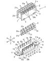
は、図2において上下左右前後方向を規定している。本実施形態の端子装置1は、図1及
び図2に示すように、ケース2と速結端子3とを備え、例えば一般住宅内等に設置される
分電盤(図示せず)内に取り付けられる。
Hereinafter, embodiments of the present invention will be described with reference to FIGS. In the following description, the vertical and horizontal directions are defined in FIG. As shown in FIGS. 1 and 2, the
ケース2は、図1及び図2に示すように全体として左右方向に延びる細長の矩形箱に形
成されており、絶縁性材料により形成され下面が開口する箱型のカバー21と、金属材に
より矩形板状に形成されてカバー21の開口を塞ぐように取り付けられるケース2の底部
たるベース22とから構成される。カバー21の上壁部21aには、図1及び図2に示す
ように前後方向中心部よりやや前方寄りに左右方向に亘って6個の挿通孔4が等間隔に貫
設される。また、各挿通孔4からやや右寄りの前方には、図2に示すように差込口5が貫
設される。
As shown in FIGS. 1 and 2, the
カバー21の前壁部21b及び後壁部21cの下端部には、図2に示すように図示しな
い分電盤内に着脱自在に取り付けるための4つの係合部6(図中では前壁部21b側の2
つのみ図示)が各々外側に向かって突設される。前記下端部の係合部6近傍には各々内部
に貫通する係止孔(図示せず)が左右方向に並設されている。カバー21の左壁部2d及
び右壁部2eの下方周縁部には、図2に示すように上方へ窪んでなる凹部7が各々設けら
れている(図中では左壁部2d側のみ図示)。また、カバー21内側には内部空間を6等
分するように5つのリブ(図示せず)が左右方向に並設される。
At the lower ends of the
(Only one is shown) protrudes outward. In the vicinity of the
ベース22は、図1、図2及び図3(b)に示すように矩形板状に形成された底部22
aと、底部22aの前後両端部から左右方向に亘って互いに対向するように上方へ延びる
前起立部22b及び後起立部22cと、を備え、左右方向から見たときに上方が開口する
コ字形状に形成されてなる。前起立部22b及び後起立部22c上部には、互いに対向す
るように上方へ延びる6つの突起片9、並びに6つの凸部10が左右方向に並設される。
また、前起立部22b及び後起立部22cの外面下部には、上述したカバー21の図示し
ない係止孔に係止するための爪部(図示せず)が突設される。
The
a and a front
In addition, a claw portion (not shown) for locking in a locking hole (not shown) of the
底部22aの左右両端部には、各々外側に延出した後に上方へ曲折され更に外側へ折り
返してなる一対の延出片8,8が配設され、その端部には孔部8a,8aが各々貫設され
る。尚、延出片8,8は、互いの外側へ折り返される端部の上下方向に対する位置が、延
出片8の厚さ幅程度だけ異なるよう設定されている。そして、ベース22には上方から後
述する端子板32が装着される。
A pair of extending
速結端子3は、図1、図2及び図3(a)に示すように6個の錠ばね31と端子板32
とから構成される。錠ばね31は、弾性を有する導電性材料によって形成された帯板の中
央部たる中央片31aと、帯板の上端部が略L字形状に曲折されることで中央片31aと
の距離を広げるように傾斜する鎖錠片31bと、前記帯板の下端部が略S字形状に曲折さ
れることで中央片31aの厚み方向に弾性を有する押圧片31cとから構成される。尚、
錠ばね31の左右方向の寸法は上述した凸部10の左右方向の寸法と略等しく、且つ突起
片9及びその右横に窪んで形成される挿入口15の両方を合わせた左右方向の寸法と略等
しく設定している。
As shown in FIG. 1, FIG. 2 and FIG. 3 (a), the
It consists of. The
The horizontal dimension of the
端子板32は、図1、図2及び図3(a)に示すように導電性を有する金属材により矩
形板状に形成された基部32aと、基部32aの前端部から左右方向に亘って上方へ延び
る立設部32bとを備え、左右方向から見たときにL字形状に形成されてなる。立設部3
2b上部には、上方へ延びる6つの端子片32cが左右方向に並設される。ここで本実施
形態の端子片32cの先端部は、図1及び図3(a)に示すように前方へ向かって曲折さ
れる。尚、端子片32cの左右方向の寸法は上述した突起片9の左右方向の寸法と略等し
く設定している。
As shown in FIGS. 1, 2 and 3A, the
Six
基部32aの左右両端部には、ベース22と同様に各々外側に延出した後に上方へ曲折
され更に外側へ折り返してなる一対の連結片11,11が配設され、その端部には孔部1
1a,11aが各々貫設される。連結片11の前後両端部には下方へ延出して更に内側へ
突出する略鉤形の係合爪11b,11bが設けられている。尚、連結片11,11は、上
述の延出片8,8と同様に互いの外側へ折り返される端部の上下方向に対する位置が、延
出片8の厚さ幅程度だけ異なるよう設定されている。
Like the base 22, a pair of connecting
1a and 11a are penetrated, respectively. At both front and rear ends of the connecting
次に本実施形態の端子装置1の組立て手順について説明する。先ず、端子板32をベー
ス22に上方から取り付ける。すなわち、端子板32の基部32aをベース22の底部2
2aに当接させて、6つの端子片32cが6つの突起片9と各々対向するように立設部3
2bを前起立部22bの内面に当接させる。このとき図2に示すように突起片9の上端部
は端子片32cの曲折される先端部により覆われる。そして、端子板32の連結片11,
11を延出片8,8に対して押し下げることで、係合爪11b、11bは、延出片8,8
の前後両端部に当接して弾性変形により外側へ撓ませた後に弾性復帰力により延出片8,
8の前記両端部と各々係合する。これにより連結片11,11が延出片8,8上面の略全
体を被覆するように取り付けられ、端子板32はベース22に装着される。
Next, the assembly procedure of the
2a, the
2b is brought into contact with the inner surface of the front standing
The engaging
The
8 are engaged with the both ends. Thus, the connecting
続いて図2に示すように6個の錠ばね31を端子板32が装着されたベース22の開口
内に向かって挿入する。このとき、錠ばね31の中央片31aをベース22の後起立部2
2cに当接させて、且つ鎖錠片31b及び押圧片31cを所望の隙間12を空けて端子板
32の端子片32c及び挿入口15に各々対向させる。そして、互いの長手方向を揃えな
がらカバー21をベース22に向かって降ろす。すると、上述したベース22の図示しな
い爪部は、カバー21の前後両壁部21b,21cを外側へ撓ませながらカバー21の開
口内に挿入される。また、カバー21内側の図示しない5つのリブは、隣り合う錠ばね3
1,31の間にある隙間と隣り合う凸部10,10の間にある隙間とに嵌入して6個の錠
ばね31の左右方向への傾きを防止している。底部22a及び基部32aの左右両端部は
、カバー21の凹部7,7に各々嵌合する。そして、前後両壁部21b,21cの弾性復
帰力により図示しない係止孔に前記爪部が各々係止する。前記係止によりカバー21とベ
ース22とが結合して、図1に示すように隙間12の真上に挿通孔4が配置するように速
結端子3がケース2内に収納される。但し、連結片11,11はケース2の左右両端下部
から外部に延出される。
Subsequently, as shown in FIG. 2, six lock springs 31 are inserted into the opening of the base 22 on which the
2c, and the
1 and 31 and the gap between adjacent
上述のような端子装置1は、図示しない分電盤内に複数個取り付けられる場合において
長手方向に沿って互いに連結させることができる。すなわち、前記分電盤内の隣接し合う
端子装置1,1において、互いの連結片11,11に貫設される孔部11a,11a、及
び延出片8,8に貫設される孔部8a,8aの中心部の位置合わせを行って、これらの4
つの孔部に挿通するボルト(図示せず)をナット(図示せず)に螺合することで連結させ
ることができる。また、端子装置1,1は、前記連結により機械的な接続だけでなく電気
的な接続もなされる。更に、上述した通り端子装置1の左右両端にある連結片11及び延
出片8の上下方向に対する位置が互いに異なるように設定されているので、2つの端子装
置1,1同士を連結させたときにケース2,2の上面同士を互いに面一とすることができ
る。
When a plurality of
The bolts (not shown) inserted through the two holes can be connected by screwing into nuts (not shown). The
そして、端子装置1の速結端子3は次のようにケース2内に入線される電線を鎖錠接続
する。すなわち、図4に示すように電線13の一端部より露出する芯線先端を上下方向に
沿って挿通孔4に挿通すると、図1に示すように前記芯線先端は各々ケース2内で対応す
る錠ばね31の押圧片31cによって端子片32cに押し当てられるとともに、鎖錠片3
1bが前記芯線先端に食い込んで係止することにより鎖錠接続される。電線13の他端部
は、例えば分電盤内の分岐ブレーカ(図示せず)と対応する電源コンセント(図示せず)
のアース端子に接続される。尚、本実施形態の端子装置1は、ケース2の差込口5、及び
挿入口15を通じて、例えばマイナスドライバの先端を挿入して鎖錠片31bの右端を下
方に押圧することで、前記鎖錠接続を解除して電線13をケース2から引き外すことがで
きる。
And the
1b is locked and locked by biting into the tip of the core wire and locking. The other end of the
Connected to the ground terminal. In addition, the
以下、本実施形態の端子装置1の作用について説明する。従来の端子装置は、従来技術
で述べたように電線を入線する際に電線の先端が端子板の先端部の周縁に形成されるバリ
に接触して邪魔になる恐れがあった。また、特許文献1に記載の端子装置は端子板の角を
切断加工することで傾斜面の周縁にバリが形成され易く、かえって接続作業性を悪くする
こともあった。これに対して本実施形態の端子片32cの先端部は、図1及び図4に示す
ように前方へ向かって曲折されており、たとえ前記先端部の周縁にバリが形成されたまま
であっても、電線13をケース2内に入線する際に電線13の芯線先端が当該バリに接触
して邪魔になるといったことがない。因って、端子板32に形成されるバリによる接続作
業性の低下を防ぐことができる。
Hereinafter, the operation of the
また、本実施形態の端子片32cの先端部には、図1及び図4に示すように切断加工に
よるものではなく、前方へ向かって曲折されることにより電線13へ向かって入線方向に
傾斜する傾斜面14が形成される。従って、上述の効果に加えて傾斜面14が電線13の
速結端子3への案内役となって電線13の入線をより行い易くすることができる。
Further, the distal end portion of the
1 端子装置
2 ケース
3 速結端子
4 挿通孔
13 電線
14 傾斜面
31 錠ばね
32 端子板
32c 端子片
DESCRIPTION OF
Claims (2)
ス内に配設され挿通孔を介して入線される電線を鎖錠接続する速結端子と、を備え、速結
端子は、少なくともケース内にて電線の入線方向に沿って配設される端子板と、端子板と
対向して配置されて入線する電線を端子板へ押圧することで電線と端子板とを電気的に接
続する錠ばねと、から構成され、
端子板の挿通孔へ向かって延びる先端部は、入線する電線から離れる方向に曲折される
ことを特徴とする端子装置。 A case formed in a box shape and penetrating through one or a plurality of insertion holes; a quick-connection terminal for locking and connecting an electric wire disposed in the case opposite to the insertion holes and inserted through the insertion holes; The quick-connect terminal includes at least a terminal plate disposed in the case along the direction in which the electric wire is inserted, and an electric wire disposed opposite to the terminal plate and pressed into the terminal plate. And a lock spring that electrically connects the terminal plate and
A terminal device characterized in that a tip portion extending toward an insertion hole of a terminal plate is bent in a direction away from an incoming electric wire.
特徴とする請求項1記載の端子装置。
The terminal device according to claim 1, wherein an inclined surface that is inclined in an incoming line direction toward the electric wire is formed at the tip portion of the terminal plate.
Priority Applications (1)
| Application Number | Priority Date | Filing Date | Title |
|---|---|---|---|
| JP2009235373A JP5385750B2 (en) | 2009-10-09 | 2009-10-09 | Terminal equipment |
Applications Claiming Priority (1)
| Application Number | Priority Date | Filing Date | Title |
|---|---|---|---|
| JP2009235373A JP5385750B2 (en) | 2009-10-09 | 2009-10-09 | Terminal equipment |
Publications (2)
| Publication Number | Publication Date |
|---|---|
| JP2011082102A true JP2011082102A (en) | 2011-04-21 |
| JP5385750B2 JP5385750B2 (en) | 2014-01-08 |
Family
ID=44075942
Family Applications (1)
| Application Number | Title | Priority Date | Filing Date |
|---|---|---|---|
| JP2009235373A Active JP5385750B2 (en) | 2009-10-09 | 2009-10-09 | Terminal equipment |
Country Status (1)
| Country | Link |
|---|---|
| JP (1) | JP5385750B2 (en) |
Cited By (1)
| Publication number | Priority date | Publication date | Assignee | Title |
|---|---|---|---|---|
| JP2015503195A (en) * | 2011-12-01 | 2015-01-29 | フェニックス コンタクト ゲーエムベーハー ウント コムパニー カーゲー | Connection terminal having a web-like conductor guide |
Citations (2)
| Publication number | Priority date | Publication date | Assignee | Title |
|---|---|---|---|---|
| JPS6212272U (en) * | 1985-07-05 | 1987-01-24 | ||
| JP3037197U (en) * | 1996-10-25 | 1997-05-06 | キムラ電機株式会社 | Screwless terminal block |
-
2009
- 2009-10-09 JP JP2009235373A patent/JP5385750B2/en active Active
Patent Citations (2)
| Publication number | Priority date | Publication date | Assignee | Title |
|---|---|---|---|---|
| JPS6212272U (en) * | 1985-07-05 | 1987-01-24 | ||
| JP3037197U (en) * | 1996-10-25 | 1997-05-06 | キムラ電機株式会社 | Screwless terminal block |
Cited By (2)
| Publication number | Priority date | Publication date | Assignee | Title |
|---|---|---|---|---|
| JP2015503195A (en) * | 2011-12-01 | 2015-01-29 | フェニックス コンタクト ゲーエムベーハー ウント コムパニー カーゲー | Connection terminal having a web-like conductor guide |
| US9343827B2 (en) | 2011-12-01 | 2016-05-17 | Phoenix Contact Gmbh & Co. Kg | Connecting terminal with a web-shaped conductor guide |
Also Published As
| Publication number | Publication date |
|---|---|
| JP5385750B2 (en) | 2014-01-08 |
Similar Documents
| Publication | Publication Date | Title |
|---|---|---|
| CN100524957C (en) | Plug connector | |
| JP5123027B2 (en) | Locking structure for screw fastening terminal | |
| JP4263533B2 (en) | Joint connector block | |
| JP3651393B2 (en) | connector | |
| JP5414836B2 (en) | connector | |
| JP2009164105A (en) | First connector, second connector, and electric connection device | |
| JP5866529B2 (en) | Terminal block and lighting apparatus using the same | |
| JP5399852B2 (en) | Terminal block | |
| WO2012066919A1 (en) | Connector for high-voltage use | |
| JP5385750B2 (en) | Terminal equipment | |
| JP3601345B2 (en) | Terminal device | |
| JP4914746B2 (en) | Electrical junction box with harness | |
| JP6100158B2 (en) | Electrical connector | |
| US6132232A (en) | Connector locking construction for a connector receptacle of an automotive electrical connection box | |
| US20170170599A1 (en) | Connector | |
| JP5724838B2 (en) | Earth connector | |
| JP5737153B2 (en) | Ground connection device and wire harness using the same | |
| JP2006352980A (en) | Electrical connection box | |
| JP4182701B2 (en) | Distribution board | |
| JP2010277732A (en) | Terminal device | |
| JP5616602B2 (en) | Terminal equipment | |
| JP5650913B2 (en) | Retaining plug | |
| JP2000231966A (en) | Electric connection box | |
| JP2011082105A (en) | Terminal device and distribution board | |
| JP2006333654A (en) | Electric connection box |
Legal Events
| Date | Code | Title | Description |
|---|---|---|---|
| A621 | Written request for application examination |
Free format text: JAPANESE INTERMEDIATE CODE: A621 Effective date: 20120605 |
|
| A977 | Report on retrieval |
Free format text: JAPANESE INTERMEDIATE CODE: A971007 Effective date: 20130516 |
|
| A131 | Notification of reasons for refusal |
Free format text: JAPANESE INTERMEDIATE CODE: A131 Effective date: 20130521 |
|
| A521 | Request for written amendment filed |
Free format text: JAPANESE INTERMEDIATE CODE: A523 Effective date: 20130722 |
|
| TRDD | Decision of grant or rejection written | ||
| A01 | Written decision to grant a patent or to grant a registration (utility model) |
Free format text: JAPANESE INTERMEDIATE CODE: A01 Effective date: 20130910 |
|
| A61 | First payment of annual fees (during grant procedure) |
Free format text: JAPANESE INTERMEDIATE CODE: A61 Effective date: 20131004 |
|
| R150 | Certificate of patent or registration of utility model |
Ref document number: 5385750 Country of ref document: JP Free format text: JAPANESE INTERMEDIATE CODE: R150 Free format text: JAPANESE INTERMEDIATE CODE: R150 |
|
| R250 | Receipt of annual fees |
Free format text: JAPANESE INTERMEDIATE CODE: R250 |
|
| R250 | Receipt of annual fees |
Free format text: JAPANESE INTERMEDIATE CODE: R250 |
|
| R250 | Receipt of annual fees |
Free format text: JAPANESE INTERMEDIATE CODE: R250 |
|
| R250 | Receipt of annual fees |
Free format text: JAPANESE INTERMEDIATE CODE: R250 |
|
| R250 | Receipt of annual fees |
Free format text: JAPANESE INTERMEDIATE CODE: R250 |
|
| R250 | Receipt of annual fees |
Free format text: JAPANESE INTERMEDIATE CODE: R250 |
|
| R250 | Receipt of annual fees |
Free format text: JAPANESE INTERMEDIATE CODE: R250 |