JP2011081663A - Image drawing apparatus, image drawing method and computer program - Google Patents
Image drawing apparatus, image drawing method and computer program Download PDFInfo
- Publication number
- JP2011081663A JP2011081663A JP2009234394A JP2009234394A JP2011081663A JP 2011081663 A JP2011081663 A JP 2011081663A JP 2009234394 A JP2009234394 A JP 2009234394A JP 2009234394 A JP2009234394 A JP 2009234394A JP 2011081663 A JP2011081663 A JP 2011081663A
- Authority
- JP
- Japan
- Prior art keywords
- perfect circle
- storage area
- end point
- registered
- divisions
- Prior art date
- Legal status (The legal status is an assumption and is not a legal conclusion. Google has not performed a legal analysis and makes no representation as to the accuracy of the status listed.)
- Granted
Links
Images

Classifications
-
- G06T11/23—
Landscapes
- Image Generation (AREA)
Abstract
【課題】真円のエッジの部分を複数の直線に分割して真円を描画するに際し、当該直線の端点の情報を高速に生成する。
【解決手段】円図形が幾つの直線に分割されるかを、当該円図形の半径rと対応付けて分割数テーブルTB1に登録しておく。また、分割された直線の端点のX座標算出用データD_xとY座標算出用データD_yとを、直線分割数Nと対応付けて端点テーブルTB2に予め登録しておく。したがって、描画図形が円図形の場合には、外形(曲線)をベジエ曲線で近似する必要がなく、三角関数の演算により、分割された直線の各分割点(端点)を直接に且つ高速に求めることができる。また、分割された直線の端点の座標の計算処理で負荷の掛かる計算処理の効率化を図ることができる。
【選択図】図1When a perfect circle is drawn by dividing an edge portion of a perfect circle into a plurality of straight lines, information on the end points of the straight lines is generated at high speed.
The number of straight lines into which a circular figure is divided is registered in a division number table TB1 in association with the radius r of the circular figure. Further, the X coordinate calculation data D_x and the Y coordinate calculation data D_y of the end points of the divided straight lines are registered in advance in the end point table TB2 in association with the straight line division number N. Therefore, when the drawing figure is a circle figure, it is not necessary to approximate the outline (curve) with a Bezier curve, and each division point (end point) of the divided straight line is obtained directly and at high speed by calculation of trigonometric functions. be able to. In addition, it is possible to improve the efficiency of the calculation processing that is burdened by the calculation processing of the coordinates of the end points of the divided straight lines.
[Selection] Figure 1
Description
本発明は、画像描画装置、画像描画方法、及びコンピュータプログラムに関し、特に、真円の全部または一部を描画するために用いて好適なものである。 The present invention relates to an image drawing apparatus, an image drawing method, and a computer program, and is particularly suitable for drawing all or part of a perfect circle.
ベクトル形式で記述されている図形データ等を表示装置に表示するためには、与えられたベクトルデータを、論理データから計算される「表示装置における座標」に変換し、描画するレンダリング処理が必要となる。従来から、ベクトルデータ(各図形データ)の処理に関する効率化の提案がなされている。特許文献1では、円を含む曲線の分割間隔を当該曲線の領域により変更することで滑らかに曲線を描画する手法が提示されている。また、特許文献2では、線分の描画について、線分自身の線幅、傾き、形状等の描画属性によって最適な処理を選択し、効率化を図る手法が提示されている。 In order to display graphic data described in vector format on a display device, it is necessary to perform rendering processing that converts the given vector data into "coordinates on the display device" calculated from logical data and draws it. Become. Conventionally, there has been a proposal for improving the efficiency of processing vector data (each graphic data). Japanese Patent Application Laid-Open No. 2004-133620 proposes a method of smoothly drawing a curve by changing the division interval of a curve including a circle depending on the area of the curve. Japanese Patent Application Laid-Open No. 2004-228620 proposes a method for improving efficiency by selecting an optimal process for drawing a line segment according to drawing attributes such as the line width, inclination, and shape of the line segment itself.
また、真円(以下、円図形と称する)の描画に着目した場合、従来は、ベクトルデータで与えられる円図形を表示装置に描画するために、まず円図形をベジエ曲線等の曲線ベクトルで近似する。そのため、円図形の半径を用いて曲線ベクトルでの近似数(分割数)を計算する。次に、特許文献3で示されているように、計算した分割数(分割点)に応じて、各曲線を描画するための制御点を求めて、円図形を曲線ベクトルデータの組合せに分割する。次に、特許文献4で示されているように、各曲線の曲線ベクトルデータを複数個の直線ベクトルデータに分割する。
When focusing on drawing a perfect circle (hereinafter referred to as a circle figure), conventionally, in order to draw a circle figure given by vector data on a display device, the circle figure is first approximated by a curve vector such as a Bezier curve. To do. Therefore, the approximate number (number of divisions) in the curve vector is calculated using the radius of the circular figure. Next, as shown in
しかしながら、前述した従来の手法では、描画する円図形のサイズに依らず一律に前述の曲線分割処理と、直線分割処理とが行われる。そのため、例えば、描画対象の円図形のサイズが小さい場合には、分割後の曲線が直線分割処理により1本の直線に分割(近似)され、ベジエ曲線の制御点や導出処理が冗長になるという課題があった。
また、複数の円図形の描画が指定された場合には、処理の繰り返しが増えるため、多大な負荷となる場合があるといった課題があった。
また、円図形から分割された直線の座標は、ラスター毎に計算されていた。そのため、ラインジョイン処理・ラインキャップ処理において補間図形として円が指定された場合等、多数の円図形の描画が指定された場合には、多大な負荷が掛かるという課題があった。
本発明は、このような問題点に鑑みてなされたものであり、真円のエッジの部分を複数の直線に分割して真円を描画するに際し、当該直線の端点の情報を高速に生成することを目的とする。
However, in the above-described conventional method, the above-described curve division processing and straight line division processing are uniformly performed regardless of the size of a circle to be drawn. Therefore, for example, when the size of a circle to be drawn is small, the divided curve is divided (approximated) into one straight line by the straight line dividing process, and the control points and the derivation process of the Bezier curve become redundant. There was a problem.
In addition, when drawing of a plurality of circular figures is designated, there is a problem that a large load may occur because the number of repetitions of processing increases.
In addition, the coordinates of the straight line divided from the circular figure are calculated for each raster. For this reason, there has been a problem that a large load is applied when drawing of a large number of circular figures is designated, such as when a circle is designated as an interpolated figure in the line join processing and line cap processing.
The present invention has been made in view of such problems. When a perfect circle is drawn by dividing the edge portion of a perfect circle into a plurality of straight lines, information on the end points of the straight line is generated at high speed. For the purpose.
本発明の画像描画装置は、真円のベクトルデータの一部または全部を、複数の直線に分割し、分割した複数の直線に基づいて、当該真円の一部または全部をラスタライズする画像描画装置であって、前記真円の分割数を、真円の大きさに係る情報に対して分割数に係る情報が予め登録された第1の記憶領域を参照して導出する第1の導出手段と、前記真円のベクトルデータの一部または全部を、前記第1の導出手段により導出された分割数で分割することにより得られる複数の直線の端点の位置を、分割数に係る情報に対して端点の位置に係る情報が予め登録された第2の記憶領域を参照して導出する第2の導出手段と、前記第2の導出手段により導出された位置に端点を有する複数の直線に基づいて、前記真円の一部または全部をラスタライズする描画手段と、を有することを特徴とする。 An image drawing apparatus according to the present invention divides a part or all of perfect circle vector data into a plurality of straight lines, and rasterizes a part or all of the perfect circle based on the plurality of divided straight lines. A first deriving unit for deriving the number of divisions of the perfect circle with reference to a first storage area in which information on the number of divisions is registered in advance with respect to information on the size of the perfect circle; The positions of the end points of a plurality of straight lines obtained by dividing a part or all of the vector data of the perfect circle by the number of divisions derived by the first deriving means with respect to the information relating to the number of divisions Based on a second deriving unit for deriving information related to the position of the end point with reference to a second storage area registered in advance, and a plurality of straight lines having the end point at the position derived by the second deriving unit , Rasterize part or all of the perfect circle And having a drawing means for drawing, a.
本発明によれば、真円の分割数に係る情報と、直線の端点の位置に係る情報とを予め登録しておくようにしたので、真円のエッジの部分を複数の直線に分割して真円を描画するに際し、当該直線の端点の情報を高速に生成することができる。 According to the present invention, since information related to the number of divisions of the perfect circle and information related to the position of the end point of the straight line are registered in advance, the edge portion of the perfect circle is divided into a plurality of straight lines. When drawing a perfect circle, the information on the end points of the straight line can be generated at high speed.
以下に、図面を参照しながら、本発明の各実施形態について説明する。
(第1の実施形態)
まず、本発明の第1の実施形態について説明する。
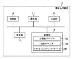
図1は、情報処理装置10の構成の一例を示す図である。情報処理装置10は、制御部11と、通信部12と、入力部13と、記憶部14と、表示部15とを有している。
制御部11は、例えばCPU等を用いて構成され、情報処理装置10を統括制御する。通信部12は、例えば通信インターフェース等を用いて構成され、外部装置との通信を行う。入力部13は、例えばキーボード及びマウス等を用いて構成され、ユーザによる情報処理装置10に対する入力操作を受け付ける。記憶部14は、例えばROM、RAM、及びHDD等を用いて構成され、情報処理装置10におけるデータ及びコンピュータプログラム等を記憶する。本実施形態では、記憶部14には、後述する分割数テーブルTB1、端点テーブルTB2、及びラスタライズパターン・データベースDBが予め設定(記憶)されている。この他、最大分割半径Rd、最大分割数M、及び最大ラスタライズ半径Rrも記憶部14に予め設定(記憶)されている。ただし、分割数テーブルTB1、端点テーブルTB2、ラスタライズパターン・データベースDB、最大分割半径Rd、最大分割数M、及び最大ラスタライズ半径Rrの少なくとも何れか1つは、情報処理装置10と通信可能な外部装置に記憶されていてもよい。また、これらのパラメータの値は、実施される形態や環境、システムの処理能力に依存する。
Embodiments of the present invention will be described below with reference to the drawings.
(First embodiment)
First, a first embodiment of the present invention will be described.
FIG. 1 is a diagram illustrating an example of the configuration of the
The
以下、これらのパラメータについて説明を行う。
最大分割半径Rd、最大分割数M(Mは2以上の整数)は、それぞれ、後述する分割数テーブルTB1、端点テーブルTB2が許容する最大円半径、分割数の最大値である。描画する円図形(真円)の半径rが最大円半径Rdを超える場合、当該円図形については、分割数テーブルTB1、端点テーブルTB2、ラスタライズパターン・データベースDBを用いたレンダリング処理は不可と判断される。この場合、当該円図形については、ベジエ曲線への分割を行う従来の処理が選択される。
Hereinafter, these parameters will be described.
The maximum division radius Rd and the maximum division number M (M is an integer greater than or equal to 2) are the maximum circle radius and the maximum number of divisions allowed by the division number table TB1 and the end point table TB2 described later, respectively. When the radius r of the circle figure (true circle) to be drawn exceeds the maximum circle radius Rd, it is determined that rendering processing using the division number table TB1, the end point table TB2, and the rasterized pattern database DB is not possible for the circle figure. The In this case, a conventional process for dividing the circular figure into a Bezier curve is selected.
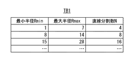
図2は、分割数テーブルTB1の一例を示す図である。
分割数テーブルTB1は、与えられた円図形の半径rから、円の直線分割数N(Nは2以上の整数)を得るためのテーブルである。図2に示すように、分割数テーブルTB1は、直線分割数Nと、当該直線分割数Nを持つ円の最大半径Rmaxと、当該円の最小半径Rminとを構成要素とする。与えられた円図形の半径rを最小半径Rminから最大半径Rmaxまでの間に含む直線分割数Nが分割数テーブルTB1に含まれる。ここで、分割数テーブルTB1の各直線分割数Nは、後述する端点テーブルTB2の効率化のために、最大分割数Mの公約数となるようにすることが望ましい。
FIG. 2 is a diagram illustrating an example of the division number table TB1.
The division number table TB1 is a table for obtaining a straight line division number N (N is an integer of 2 or more) of a circle from the radius r of a given circular figure. As shown in FIG. 2, the division number table TB1 includes the straight line division number N, the maximum radius Rmax of the circle having the straight line division number N, and the minimum radius Rmin of the circle. The division number table TB1 includes the straight line division number N including the radius r of the given circular figure from the minimum radius Rmin to the maximum radius Rmax. Here, it is desirable that each straight line division number N of the division number table TB1 is a common divisor of the maximum division number M in order to improve the efficiency of the end point table TB2 described later.
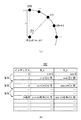
図3は、円図形を複数の直線に分割する場合の当該直線の端点の一例(図3(a))と、端点テーブルTB2の一例(図3(b))とを示す図である。
端点テーブルTB2は、円図形を複数の直線に分割する際に、各直線(線分)の端点の座標を予め行いテーブル化したものである。各直線の端点の座標は、三角関数等の計算を行うことにより求めることができる。通常、N個に直線分割された線分の端点EPn(xn, yn)(n = 0, 1, ・・・, N-1)は、図3(a)に示すように、円の中心点の座標(xo, yo)、円の半径r、及び基準点からの角度θn[rad]により三角関数を用いて求められる。基準点からの角度θnとは、中心点と基準点EP0とを結ぶ直線と、中心点と端点EPnとを結ぶ直線とのなす角度である。基準点からの角度θnは、円の分割数が定まっていれば基準点EP0を0(ゼロ)とする、N個に直線分割された線分の端点を特定する端点番号nを用いて求めることができ、その値を用いた三角関数の計算も予めテーブル化することが可能である。
FIG. 3 is a diagram illustrating an example of the end points of the straight line (FIG. 3A) and an example of the end point table TB2 (FIG. 3B) when the circular figure is divided into a plurality of straight lines.
The end point table TB2 is a table in which the coordinates of the end points of each straight line (line segment) are obtained in advance when the circular figure is divided into a plurality of straight lines. The coordinates of the end points of each straight line can be obtained by calculating a trigonometric function or the like. Normally, the end points EPn (xn, yn) (n = 0, 1,..., N−1) of the line segment divided into N pieces are the center points of the circle as shown in FIG. Is obtained by using a trigonometric function based on the coordinates (xo, yo), the radius r of the circle, and the angle θn [rad] from the reference point. The angle θn from the reference point is an angle formed by a straight line connecting the center point and the reference point EP0 and a straight line connecting the center point and the end point EPn. The angle θn from the reference point is obtained by using the end point number n that specifies the end points of the line segment divided into N lines, where the reference point EP0 is 0 (zero) if the number of divisions of the circle is determined. The calculation of trigonometric functions using the values can be tabulated in advance.
本実施形態では図3(b)に示すように、基準点EP0からの端点番号n(分割数)をインデックスとして、当該端点番号nの端点のX座標算出用データ、Y座標算出用データをそれぞれ、D_x、D_yとしてテーブル化したものが端点テーブルTB2である。
ここで、端点テーブルTB2を、円図形の半径r、直線分割数N毎に複数保持する必要はなく、最大分割数Mで作成された端点テーブルTB2を、異なる直線分割数Nの端点のX、Y座標を求める際にも利用でき、単一のテーブルのみで対応できる。その方法として、まず、所望する円図形の直線分割数Nと最大分割数Mとから、端点テーブルTB2の参照間隔をM/Nとする。そして、端点番号nの端点の座標を求める際には、n×M/Nをインデックスとして端点テーブルTB2からデータを取得するようにする(図3(b)の左端を参照)。この方法により、単一の端点テーブルTB2のみで、直線分割数Nに依存せずに、N個に直線分割された線分の端点の座標を得ることができる。したがって、複数のテーブルに冗長な情報を格納するといったことが無く、効率良くデータを保持することが可能である。直線分割で対応可能な分割数(円半径)は、端点テーブルTB2の分割数に依存するため、端点テーブルTB2の分割数(最大分割数M)は出来得る限り大きな値であることが望ましい。このように本実施形態では、端点テーブルTB2には、M個のインデックスがある。
In this embodiment, as shown in FIG. 3B, the end point number n (number of divisions) from the reference point EP0 is used as an index, and the X-coordinate calculation data and the Y-coordinate calculation data of the end point of the end point number n are respectively displayed. , D_x, D_y are tabulated as the end point table TB2.
Here, there is no need to hold a plurality of end point tables TB2 for each radius r of the circular figure and the number of straight line divisions N. The end point table TB2 created with the maximum number of divisions M can be stored as X, It can also be used when obtaining the Y coordinate, and can be handled with only a single table. As the method, first, the reference interval of the end point table TB2 is set to M / N from the desired straight line division number N and maximum division number M of the circular figure. Then, when obtaining the coordinates of the end point of the end point number n, data is acquired from the end point table TB2 using n × M / N as an index (see the left end of FIG. 3B). With this method, it is possible to obtain the coordinates of the end points of the line segment that is divided into N straight lines, without depending on the straight line division number N, using only the single end point table TB2. Therefore, redundant information is not stored in a plurality of tables, and data can be held efficiently. Since the number of divisions (circular radius) that can be handled by straight line division depends on the number of divisions in the end point table TB2, the number of divisions (maximum division number M) in the end point table TB2 is preferably as large as possible. Thus, in the present embodiment, the end point table TB2 has M indexes.
直線分割された線分の端点EPnのX座標xn及びY座標ynと、基準点からの角度θnは、それぞれ(1)式〜(3)式で表され、端点テーブルTB2から得られる端点EPnのX座標xn及びY座標ynは、それぞれ(4)式、(5)式で表される。
Xn=xo+r×sin(θn) ・・・(1)
Yn=yo−r×cos(θn) ・・・(2)
θn=n×2π/N ・・・(3)
Xn=xo+r×TB2[n×M/N, 1] ・・・(4)
Yn=yo−r×TB2[n×M/N, 2] ・・・(5)
ここで、TB2[n×M/N, 1]は、端点テーブルTB2のインデックスn×M/NのD_xの値を示し、TB2[n×M/N, 2]は、端点テーブルTB2のインデックスn×M/NのD_yを示す。
The X-coordinate xn and Y-coordinate yn of the end point EPn of the straight line segment and the angle θn from the reference point are expressed by the equations (1) to (3), respectively, of the end point EPn obtained from the end point table TB2. The X coordinate xn and the Y coordinate yn are expressed by the equations (4) and (5), respectively.
Xn = xo + r × sin (θn) (1)
Yn = yo−r × cos (θn) (2)
θn = n × 2π / N (3)
Xn = xo + r × TB2 [n × M / N, 1] (4)
Yn = yo-r * TB2 [n * M / N, 2] (5)
Here, TB2 [n × M / N, 1] indicates the value of D_x of the index n × M / N of the endpoint table TB2, and TB2 [n × M / N, 2] indicates the index n of the endpoint table TB2. X Indicates D_y of M / N.
最大ラスタライズ半径Rrは、分割後の各線分をラスタライズする際に、後述するラスタライズパターン・データベースDBを用いた手法が許容する円図形の最大半径である。
ラスタライズパターン・データベースDBは、分割された線分の描画内容を表すラスタライズデータをデータベース化したものである。
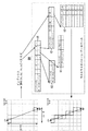
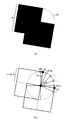
図4は、分割後の線分からラスタライズパターン・データベースDBを用いてラスタライズデータを得る手法の一例を説明する図である。
図4に示すように、ラスタライズパターン・データベースDBは、開始位置CP及び終了位置NP(両端点)の相対的な位置関係の一例として、両端点の座標を整数化したものの差分(dx, dy)と該差分の最大値MAX(dx, dy)をインデックスとする。また、ラスタライズパターン・データベースDBは、分割された線分のラスタライズパターン・データとして、例えば、直前のラスターに対するX方向の変化分及びY方向の変化分(l_dx, l_dy)を格納する。
The maximum rasterization radius Rr is a maximum radius of a circular figure allowed by a method using a rasterization pattern database DB described later when rasterizing each segment after division.
The rasterized pattern database DB is a database of rasterized data representing the drawing contents of the divided line segments.
FIG. 4 is a diagram for explaining an example of a technique for obtaining rasterized data from the divided line segments using the rasterized pattern database DB.
As shown in FIG. 4, the rasterized pattern database DB is an example of the relative positional relationship between the start position CP and the end position NP (end points), and the difference (dx, dy) between the coordinates of the end points converted to integers. And the maximum difference MAX (dx, dy) as an index. Further, the rasterized pattern database DB stores, for example, a change in the X direction and a change in the Y direction (l_dx, l_dy) with respect to the immediately preceding raster as rasterized pattern data of the divided line segments.
図4に示す例では、データ81に示すように、両端点の座標を整数化した際の差分の最大値MAX(dx, dy)をインデックス1として、ラスタライズパターン・データを大きさ毎に分類・格納したデータ82へのエントリを格納する。データ82は、各線分の大きさ毎に両端点の差分[dx, dy]をインデックス2として、各ラスタライズパターン・データ83へのエントリを有する。各ラスタライズパターン・データ83は、線分の開始点を基準とした番号をインデックス3とし、直前のラスターの座標に対するX方向の変化分とY方向の変化分をそれぞれl_dx、l_dyとして格納している。
ここで、円図形から分割される線分の長さ、傾きは限られている。したがって、ラスタライズパターン・データ83として、線分の全てのラスタライズパターンをデータベース化する必要はない。このように、必要なラスタライズパターン・データのみを保持することで、格納するデータ量を削減し、処理の効率化を図ることができる。
In the example shown in FIG. 4, as shown in the
Here, the length and inclination of the line segment divided from the circular figure are limited. Therefore, it is not necessary to create a database of all rasterized patterns of line segments as rasterized pattern data 83. Thus, by holding only the necessary rasterized pattern data, the amount of data to be stored can be reduced and the processing efficiency can be improved.
端点テーブルTB2、及びラスタライズパターン・データベースDBの少なくとも何れか一方には、円周全体分のデータ(真円の全体に対応するデータ)を格納する必要はない。円の対称性を利用し、真円の一部分に対応するデータ(例えば1象限分(1/4円周分)のデータ)を格納する。そして、異なる象限内の端点(真円の他の部分に対応する端点)の計算や、線分(真円の他の部分に対応する線分)のラスタライズ時には、符号、XY値を入れ替える処理を行うことで、格納するデータ量を削減し、処理の効率化を図ることができる。 It is not necessary to store data for the entire circumference (data corresponding to the entire perfect circle) in at least one of the end point table TB2 and the rasterized pattern database DB. Data corresponding to a part of a perfect circle (for example, data for one quadrant (1/4 circle circumference)) is stored using the symmetry of the circle. Then, when calculating the end points in different quadrants (end points corresponding to other parts of the perfect circle) and rasterizing the line segments (line segments corresponding to other parts of the perfect circle), processing for switching the sign and XY values is performed. By doing so, the amount of data to be stored can be reduced and the processing efficiency can be improved.
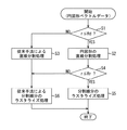
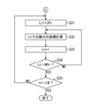
図5は、円図形のベクトルデータからラスタライズデータを生成する際の情報処理装置10の処理の一例を説明するフローチャートである。
円図形のベクトルデータの描画が指定されると、ステップS1において、制御部11は、描画対象の円図形の半径rが最大分割半径Rd以下であるか否かを判定する。この判定の結果、指定された円図形の半径rが最大分割半径Rd以下である場合には、ステップS2に進み、分割数テーブルTB1と端点テーブルTB2とを用いた後述する円図形の直線分割処理が実行される。
一方、指定された円図形の半径rが最大分割半径Rd以下でない場合には、ステップS3に進み、後述する曲線分割処理を経て直線分割を行う従来手法に基づく直線分割処理が実行される。
FIG. 5 is a flowchart for explaining an example of processing of the
When the drawing of the circular graphic vector data is designated, in step S1, the
On the other hand, when the radius r of the designated circular figure is not less than or equal to the maximum division radius Rd, the process proceeds to step S3, and a straight line division process based on a conventional method of performing a straight line division through a curve division process described later is executed.
ステップS2の処理の後のステップS4では、制御部11は、円図形の半径rが最大ラスタライズ半径Rr以下であるか否かを判定する。この判定の結果、円図形の半径rが最大ラスタライズ半径Rr以下である場合には、ステップS5に進み、後述するラスタライズデータパターン・データベースDBを用いた分割線分のラスタライズ処理が実行される。
ステップS4の判定の結果、円図形の半径rが最大ラスタライズ半径Rr以下でない場合、又はステップS3の処理が実行された場合には、ステップS6に進む。そして、各線分について、ラスター単位で表示装置における座標の算出を行う従来手法に基づくラスタライズ処理が実行される。
In step S4 after the process of step S2, the
As a result of the determination in step S4, if the radius r of the circular figure is not less than or equal to the maximum rasterizing radius Rr, or if the process of step S3 is executed, the process proceeds to step S6. Then, for each line segment, rasterization processing based on a conventional method for calculating coordinates in the display device in raster units is executed.
次に、図6〜図9のフローチャートを参照しながら、図5のフローチャートの詳細を説明する。
まず、円図形のベクトルデータの描画が指示されると、図6のステップS11において制御部11は、描画対象の円図形の半径rと、最大分割半径Rdとを取得する。
次に、ステップS12において、制御部11は、描画対象の円図形の半径rが最大分割半径Rd以下であるか否かを判定する。この判定の結果、描画対象の円図形の半径rが最大分割半径Rd以下である場合には、分割数テーブルTB1及び端点テーブルTB2を用いた端点の座標の算出が可能と判断してステップS13に進む。一方、描画対象の円図形の半径rが最大分割半径Rd以下でない場合には、分割数テーブルTB1及び端点テーブルTB2を用いた端点の座標の算出は不可と判断し、図8のステップS25に進む。後述するように、ステップS25以降では、円図形を複数の曲線ベクトルに分割した後に直線分割する従来手法に基づく直線分割処理が行われる。
Next, the details of the flowchart of FIG. 5 will be described with reference to the flowcharts of FIGS.
First, when the drawing of vector data of a circular graphic is instructed, in step S11 in FIG. 6, the
Next, in step S12, the
ステップS13に進むと、制御部11は、描画対象の円図形の半径rを用いて分割数テーブルTB1から、描画対象の円図形の直線分割数Nを直接取得すると共に、最大分割数Mを取得する。
このように本実施形態では、例えば、ステップS13の処理を実行することにより第1の導出手段の一例が実現され、分割数テーブルTB1を用いることにより第1の記憶領域の一例が実現される。
次に、ステップS14において、制御部11は、最大分割数Mで作成された単一の端点テーブルTB2から所望の直線分割数Nに対応したデータの参照を可能とするための参照間隔M/Nを計算する。
次に、ステップS15において、制御部11は、端点番号n(n = 0, 1, ・・・、N-1)と参照間隔M/Nとから、端点テーブルTB2の参照インデックスをn×M/Nとして所望の端点の座標算出用データD_x、D_yを取得する。
In step S13, the
As described above, in the present embodiment, for example, an example of the first derivation unit is realized by executing the process of step S13, and an example of the first storage area is realized by using the division number table TB1.
Next, in step S14, the
Next, in step S15, the
次に、ステップS16において、制御部11は、ステップS15で取得した座標算出用データD_x、D_yを用いて、端点EPnの座標(xn, yn)を、前述した(4)式、(5)式により計算する。このとき、端点テーブルTB2の保持するデータが第一象限分であり、所望するデータが第二象限の端点であった場合、制御部11は、端点のY座標算出用データD_yの符号を反転させる。このように、制御部11は、異なる象限の端点テーブルTB2の座標算出用データを所望の端点の座標算出用データに適応させる手段を有する。 次に、ステップS17において、制御部11は、現在の端点番号nに1を加算したものが、描画対象の円図形の直線分割数N以上であるか否かを判定する。この判定の結果、現在の端点番号nに1を加算したものが、描画対象の円図形の直線分割数N以上でない場合には、ステップS15に戻り、現在の端点番号nに1を加算したものを現在の端点番号nとし、当該端点番号nについて処理を実行する。このようにして、N個の端点の座標が計算されると、図7のステップS18に進む。
以上のように本実施形態では、例えば、ステップS14〜S17の処理を実行することにより第2の導出手段の一例が実現され、端点テーブルTB2を用いることにより第2の記憶領域の一例が実現される。
Next, in step S16, the
As described above, in the present embodiment, for example, an example of the second derivation unit is realized by executing the processes of steps S14 to S17, and an example of the second storage area is realized by using the end point table TB2. The
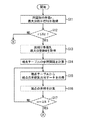
図7のステップS18に進むと、制御部11は、最大ラスタライズ半径Rrを取得する。
次に、ステップS19において、制御部11は、描画対象の円図形の半径rが最大ラスタライズ半径Rr以下であるか否かを判定する。この判定の結果、描画対象の円図形の半径rが最大ラスタライズ半径Rr以下である場合には、ラスタライズパターン・データベースDBを用いたラスタライズ処理が可能と判断してステップS20へ進む。一方、描画対象の円図形の半径rが最大ラスタライズ半径Rr以下でない場合には、図9のステップS31に進む。ステップS31では、後述するように、各線分について、表示装置における座標の算出をラスター単位で行う従来手法に基づくラスタライズ処理が実行される。
In step S18 of FIG. 7, the
Next, in step S <b> 19, the
ステップS20に進むと、制御部11は、複数に分割された線分の両端点の座標を整数化し、その差分dn=(dx, dy)を計算する(図4を参照)。
次に、ステップS21において、制御部11は、ステップS20で計算した差分dnの最大値MAX(dx, dy)を計算する。
次に、ステップS22において、制御部11は、差分dnと、当該差分dnの最大値MAX(dx, dy)とをインデックスとしてラスタライズパターン・データベースDBから、所望の線分のラスタライズパターン・データを一意に取得する。
次に、ステップS23において、制御部11は、線分の開始端点CPに、ステップS22で取得したラスタライズパターン・データを順次加算することで線分の表示装置における座標を高速に求める。
In step S20, the
Next, in step S21, the
Next, in step S22, the
Next, in step S23, the
次に、ステップS24において、制御部11は、現在の端点番号nに1を加算したものが、描画対象の円図形の直線分割数N以上であるか否かを判定する。この判定の結果、現在の端点番号nに1を加算したものが、描画対象の円図形の直線分割数N以上でない場合には、ステップS15に戻り、現在の端点番号nに1を加算したものを現在の端点番号nとし、当該端点番号nについて処理を実行する。このようにして、N個の線分のラスタライズデータが得られ(円図形のラスタライズが行われ)、描画対象の円図形の直線分割数N以上になると、本フローチャートによる処理を終了する。
以上のように本実施形態では、例えば、ステップS20〜24の処理を実行することにより第3の導出手段の一例が実現され、ラスタライズパターン・データベースDBを用いることにより第3の記憶領域の一例が実現される。
Next, in step S24, the
As described above, in the present embodiment, for example, an example of the third derivation unit is realized by executing the processing of steps S20 to S24, and an example of the third storage area is realized by using the rasterized pattern database DB. Realized.
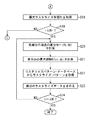
前述したように、図6のステップS12において、描画対象の円図形の半径rが最大分割半径Rd以下でないと判定されると、分割数テーブルTB1及び端点テーブルTB2を用いた端点の座標の算出は不可と判断し、図8のステップS25に進む。
ステップS25に進むと、制御部11は、円図形のベジエ曲線(以下の説明では必要に応じて分割曲線Cnと称する)への分割数Ncを1象限1曲線として計算する。
次に、ステップS26において、制御部11は、分割曲線Cn(n = 1, 2, ・・・, Nc)の開始点、終了点を含む制御点を計算する。制御点の計算は、特許文献3に記載されているように公知の技術であるので、ここでは、詳細な説明を省略する。
次に、ステップS27において、制御部11は、直線近似方法を用いて、ステップS26で計算された制御点から分割曲線Cnの直線分割数Nnを計算する。直線近似方法は、特許文献4に記載されているように公知の技術であるので、ここでは、詳細な説明を省略する。
As described above, when it is determined in step S12 in FIG. 6 that the radius r of the circle to be drawn is not less than or equal to the maximum division radius Rd, the coordinates of the endpoints using the division number table TB1 and the endpoint table TB2 are calculated. It judges that it is impossible, and progresses to step S25 of FIG.
In step S25, the
Next, in step S26, the
Next, in step S27, the
次に、ステップS28において、制御部11は、分割曲線Cnのi番目の分割線分Si(i = 1, 2, ・・・, Nn)の両端点の座標を、前述した(1)式〜(3)式を用いて計算する。
次に、ステップS29において、制御部11は、現在のiに1を加算したものが、分割曲線Cnの直線分割数Nn以上であるか否かを判定する。この判定の結果、現在のiに1を加算したものが、分割曲線Cnの直線分割数Nn以上でない場合には、ステップS28に戻り、現在のiに1を加算したものを現在のiとし、当該i番目の分割線分Siの両端点の座標を計算する。
一方、現在のiに1を加算したものが、分割曲線Cnの直線分割数Nn以上となり、分割曲線Cnの各分割線分Siの両端点の座標が計算されると、ステップS30に進む。ステップS30に進むと、制御部11は、現在の端点番号nに1を加算したものが、分割曲線Cnの分割数Nc以上であるか否かを判定する。この判定の結果、現在の端点番号nに1を加算したものが、分割曲線Cnの分割数Nc以上でない場合には、ステップS26に戻り、現在の端点番号nに1を加算したものを現在の端点番号nとし、当該端点番号nについて処理を実行する。このようにして、ステップS26〜S29の処理をNc個の分割曲線毎に繰り返し、円図形の直線分割が行われると、図9のステップS31に進む。図8のフローチャートが実行された場合、円図形の半径rが大きく、直線分割後の各線分のラスタライズパターンが多数あると判断される。そこで、本実施形態では、図8のフローチャートが実行された場合には、図9のフローチャートを実行し、各線分について、ラスター単位で表示装置における座標の算出を行う従来手法に基づくラスタライズ処理が行われる。
Next, in step S28, the
Next, in step S29, the
On the other hand, the value obtained by adding 1 to the current i is equal to or greater than the number of straight lines Nn of the dividing curve Cn, and when the coordinates of both end points of each dividing line segment Si of the dividing curve Cn are calculated, the process proceeds to step S30. In step S30, the
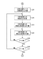
図9のステップS31に進むと、制御部11は、線分Sn(n = 0, 1, ・・・, N-1)の処理ラスター位置Lnとして開始点CPnをセットする。
次に、ステップS32において、制御部11は、線分Snの処理ラスター位置Lnにおける表示装置上の座標を計算する。その後、ステップS33において、制御部11は、現在の処理ラスター位置Lnに1を加算し、現在の処理ラスター位置を次の位置(ラスター)へ移動させる。
次に、ステップS34において、制御部11は、現在の処理ラスター位置Lnが、線分Snの終了点NPnを超えたか否かを判定する。この判定の結果、現在の処理ラスター位置Lnが、線分Snの終了点NPnを超えていない場合には、ステップS32に戻り、現在の処理ラスター位置Lnについて処理を行う。そして、現在の処理ラスター位置Lnが、線分Snの終了点NPnを超え、線分Snの終了点NPnの座標が計算されると(線分Snのラスタライズ処理が行われると)、ステップS35に進む。
ステップS35に進むと、制御部11は、現在の端点番号nに1を加算したものが、描画対象の円図形の直線分割数N以上であるか否かを判定する。この判定の結果、現在の端点番号nに1を加算したものが、描画対象の円図形の直線分割数N以上でない場合には、ステップS15に戻り、現在の端点番号nに1を加算したものを現在の端点番号nとし、当該端点番号nについて処理を実行する。このようにして、ステップS31〜S34の線分のラスタライズ処理がN個の線分毎に繰り返し行われ、円図形のラスタライズ処理が行われると、本フローチャートによる処理を終了する。
When proceeding to step S31 of FIG. 9, the
Next, in step S32, the
Next, in step S34, the
In step S35, the
以上のように本実施形態では、円図形が幾つの直線に分割されるかを、当該円図形の半径rと対応付けて分割数テーブルTB1に登録しておく。また、分割された直線の端点のX座標算出用データD_xとY座標算出用データD_yとを、直線分割数Nと対応付けて端点テーブルTB2に予め登録しておく。したがって、描画図形が円図形の場合には、外形(曲線)をベジエ曲線で近似する必要がなく、分割された直線の各分割点(端点)を直接に且つ高速に求めることができる。また、分割された直線の端点の座標の計算処理で負荷の掛かる計算処理の効率化を図ることができる。よって、真円のエッジの部分を複数の直線に分割して真円を描画するに際し、当該直線の端点の情報を高速に生成することができる。
また、本実施形態では、線分をラスタライズしたデータをラスタライズパターンとして、線分の両端点の座標の差分と対応付けてラスタライズパターン・データベースDBに予め登録しておく。したがって、線分とラスター(スキャンライン)との交点の座標をその都度(スキャンライン毎に)計算することなく線分を描画することが可能になる。
As described above, in this embodiment, how many straight lines a circle figure is divided into is registered in the division number table TB1 in association with the radius r of the circle figure. Further, the X coordinate calculation data D_x and the Y coordinate calculation data D_y of the end points of the divided straight lines are registered in advance in the end point table TB2 in association with the straight line division number N. Therefore, when the drawing figure is a circle figure, it is not necessary to approximate the outer shape (curve) with a Bezier curve, and each division point (end point) of the divided straight line can be obtained directly and at high speed. In addition, it is possible to improve the efficiency of the calculation processing that is burdened by the calculation processing of the coordinates of the end points of the divided straight lines. Therefore, when a perfect circle is drawn by dividing the edge portion of the perfect circle into a plurality of straight lines, information on the end points of the straight lines can be generated at high speed.
In the present embodiment, data obtained by rasterizing a line segment is registered as a rasterized pattern in advance in the rasterized pattern database DB in association with the difference between the coordinates of both end points of the line segment. Therefore, the line segment can be drawn without calculating the coordinates of the intersection of the line segment and the raster (scan line) each time (for each scan line).
尚、本実施形態で説明した図5のステップS3(図8)、ステップS6(図9)は、それぞれ、従来の手法で実現できる直線分割処理、ラスタライズ処理であれば、前述した方法に限定されるものではない。
また、本実施形態では、円図形が幾つの直線に分割されるかを、当該円図形の半径rと対応付けて分割数テーブルTB1に登録した場合を例に挙げて説明した。しかしながら、円図形の半径rの代わりに、円図形の直径や円周等、円図形(真円)の大きさの情報を用いるようにしてもよい。
また、本実施形態では、円図形の半径rと、最大分割半径Rd及び最大ラスタライズ半径Rrとの比較結果に応じて処理を切り替えるようにした。しかしながら、最大分割半径Rd及び最大ラスタライズ半径Rrの少なくとも何れか一方を設定せずに、図6のステップS13、S20以降の処理を無条件で実行するようにしてもよい。
また、本実施形態では、情報処理装置10が画像描画装置の一例である場合について説明したが、画像描画装置は、印刷装置等であってもよい。
Note that step S3 (FIG. 8) and step S6 (FIG. 9) in FIG. 5 described in the present embodiment are limited to the above-described methods as long as they are straight line division processing and rasterization processing that can be realized by a conventional method, respectively. It is not something.
Further, in the present embodiment, an example has been described in which how many straight lines a circle figure is divided into is registered in the division number table TB1 in association with the radius r of the circle figure. However, instead of the radius r of the circular figure, information on the size of the circular figure (perfect circle) such as the diameter and circumference of the circular figure may be used.
In the present embodiment, the processing is switched according to the comparison result between the radius r of the circular figure, the maximum division radius Rd, and the maximum rasterization radius Rr. However, the processing after steps S13 and S20 in FIG. 6 may be executed unconditionally without setting at least one of the maximum division radius Rd and the maximum rasterization radius Rr.
In the present embodiment, the case where the
(第2の実施形態)
次に、本発明の第2の実施形態について説明する。前述した第1の実施形態では、一般的な円図形(の全部)を描画する場合を例に挙げて説明した。これに対し、本実施形態では、ラインジョイン処理、ラインキャップ処理において、補間図形として円が指定された場合の描画について説明する。この場合には、円図形の必要な一部だけを選択し描画する必要がある。このように本実施形態と前述した第1の実施形態とは、ラスタライズ処理の対象となる図形が異なることによる処理(曲線の図形を複数の直線に分割し、分割した直線の端点の座標を導出する処理)が主として異なる。したがって、本実施形態の説明において、前述した第1の実施形態と同一の部分については、図1〜図9に付した符号と同一の符号を付す等して詳細な説明を省略する。
(Second Embodiment)
Next, a second embodiment of the present invention will be described. In the first embodiment described above, the case of drawing a general circle figure (all) is described as an example. On the other hand, in the present embodiment, description will be given of drawing when a circle is designated as an interpolated figure in line join processing and line cap processing. In this case, it is necessary to select and draw only a necessary part of the circular figure. As described above, the present embodiment and the first embodiment described above are processes by which the graphic to be rasterized is different (the curved graphic is divided into a plurality of straight lines, and the coordinates of the end points of the divided straight lines are derived. Processing) is mainly different. Therefore, in the description of the present embodiment, the same parts as those in the first embodiment described above are denoted by the same reference numerals as those in FIGS.
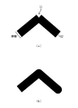
図10は、ラインジョイン処理及びラインキャップ処理を説明する図である。
図10(a)に示すように、線幅のある線の描画を行う場合、折れ線部分に隙間51が発生する。この隙間51を直線、折れ線、円等の所定の形状で、図10(b)に示すように補間する処理がラインジョイン処理である。一方、図10(a)に示すように、線幅のある線の描画を行う場合に線端52を直線、円等の所定の形状で図10(b)に示すように補間する処理がラインキャップ処理である。
FIG. 10 is a diagram for explaining line join processing and line cap processing.
As shown in FIG. 10A, when a line having a line width is drawn, a
図11は、隙間が生じている折れ線部分と、ラインジョイン処理により当該隙間を補間する円図形の端点の一例を示す図である。
図11(a)に示すように、線幅wを持つ折れ線を、ラインジョイン処理において、円で補間して描画する場合、折れ線の隙間を破線141で示す形状に円図形で補間する必要がある。以下の説明では、必要に応じてこの円図形を補間円図形と称する。
図12は、直線分割処理の一例を説明するフローチャートであり、図6の代わりに実行されるものである。本実施形態においても、第1の実施形態で説明したように、予めパラメータが設定される。
まず、図12のステップS41において、制御部11は、補間円図形の半径rと、最大分割数Rdとを取得する。このとき、ラインジョイン処理、ラインキャップ処理における補間円図形の半径rは、描画線分(折れ線)の線幅wの2分の1となるので、制御部11は、まず線幅wを取得し、取得した線幅wを1/2倍したものを補間円図形の半径rとして求める。
FIG. 11 is a diagram illustrating an example of a polygonal line portion in which a gap is generated and end points of a circular figure that interpolates the gap by line join processing.
As shown in FIG. 11A, when a polygonal line having a line width w is drawn by interpolating with a circle in the line join process, it is necessary to interpolate the gap between the polygonal lines with a circle in the shape indicated by the
FIG. 12 is a flowchart for explaining an example of the straight line dividing process, which is executed instead of FIG. Also in the present embodiment, parameters are set in advance as described in the first embodiment.
First, in step S41 of FIG. 12, the
次に、ステップS42において、制御部11は、描画対象の円図形の半径rが最大分割半径Rd以下であるか否かを判定する。この判定の結果、描画対象の円図形の半径rが最大分割半径Rd以下でない場合には、前述した図8のステップS25に進む。これにより、図11(a)の破線141に示す補間円図形が図8に示した処理に従って直線分割される。
一方、描画対象の円図形の半径rが最大分割半径Rd以下である場合には、ステップS43に進む。ステップS43に進むと、制御部11は、描画対象の円図形の半径rを用いて分割数テーブルTB1から、描画対象の円図形(1周分の円)の直線分割数Nを直接取得すると共に、最大分割数Mを取得する。
このように本実施形態では、例えば、ステップS43の処理を実行することにより第1の導出手段の一例が実現され、分割数テーブルTB1を用いることにより第1の記憶領域の一例が実現される。
次に、ステップS44において、制御部11は、最大分割数Mで作成された単一の端点テーブルTB2から所望の直線分割数Nに対応したデータ参照を可能とするための参照間隔M/Nを計算する。
Next, in step S42, the
On the other hand, if the radius r of the circle to be drawn is equal to or less than the maximum division radius Rd, the process proceeds to step S43. In step S43, the
Thus, in the present embodiment, for example, an example of the first deriving unit is realized by executing the process of step S43, and an example of the first storage area is realized by using the division number table TB1.
Next, in step S44, the
図11に示す例では、図11(a)における折れ線の隙間を円図形で補間するため、図11(b)に示すように、当該隙間を円図形で補完した場合に、折れ線の角点SP、FPの間に挟まれる端点EPns〜EPneまでを求める必要がある。
そこで、ステップS45において、制御部11は、必要な端点の開始端点番号nsと終了端点番号neとを計算する。その方法として、まず、制御部11は、基準点EP0から各角点SP、FPまでの角度θs、θe[rad]を求める。ここで、基準点EP0から角点SPまでの角度θsは、中心点と基準点EP0とを結ぶ直線と、中心線と角点SPとを結ぶ直線とのなす角度である。また、基準点EP0から角点FPまでの角度θeは、中心点と基準点EP0とを結ぶ直線と、中心線と角点FPとを結ぶ直線とのなす角度である。次に、制御部11は、端点の開始端点番号nsを(n−1)×2π/M<θs≦n×2π/Mを満たすnとして計算する。同様に制御部11は、端点の終了端点番号neをn×2π/M≦θe<(n+1)×2π/Mを満たすnとして計算する。これにより、円図形の描画に必要な端点番号が求まる。端点の開始端点番号nsが求まると、ステップS46において、制御部11は、端点座標計算の開始点をn=nsとしてセットする。
In the example shown in FIG. 11, since the gap between the broken lines in FIG. 11A is interpolated with a circular figure, as shown in FIG. 11B, when the gap is complemented with a circular figure, the corner point SP of the broken line is obtained. , It is necessary to obtain end points EPns to EPne sandwiched between FPs.
Therefore, in step S45, the
次に、ステップS47において、制御部11は、端点番号n(n = ns, ns+1, ・・・, ne)と参照間隔M/Nとから、端点テーブルTB2の参照インデックスをn×M/Nとして所望の端点の座標算出用データD_x、D_yを取得する。
次に、ステップS48において、制御部11は、ステップS47で取得した座標算出用データD_x、D_yを用いて、端点EPnの座標(xn, yn)を、前述した(4)式、(5)式により計算する。本実施形態でも、制御部11は、異なる象限の端点テーブルTB2の座標算出用データを所望の端点の座標算出用データに適応させる手段を有する。
Next, in step S47, the
Next, in step S48, the
次に、ステップS49において、制御部11は、現在の端点番号nに1を加算したものが、端点の終了端点番号ne以上であるか否かを判定する。この判定の結果、現在の端点番号nに1を加算したものが、端点の終了端点番号ne以上でない場合には、ステップS47に戻り、現在の端点番号nに1を加算したものを現在の端点番号nとし、当該端点番号nについて処理を実行する。このようにして、(ne−ns)個の端点の座標が計算されると、図7のステップS18に進む。そして、補間図形である弧SP-FPの各分割線分(線分SP-EPns、EPne-FPを含む)を第1の実施形態で説明したのと同様にしてラスタライズ処理を行うことで必要な部分だけを描画する。
以上のように本実施形態では、例えば、ステップS44〜S49の処理を実行することにより第2の導出手段の一例が実現され、端点テーブルTB2を用いることにより第2の記憶領域の一例が実現される。
Next, in step S49, the
As described above, in the present embodiment, for example, an example of the second derivation unit is realized by executing the processing of steps S44 to S49, and an example of the second storage area is realized by using the end point table TB2. The
以上のように本実施形態では、ラインジョイン処理・ラインキャップ処理を行うに際し、線の線幅の1/2倍を半径rとする円図形として、分割数テーブルTB1から直線分割数Nを取得する。そして、補間する領域(破線141)に対応する端点の開始端点番号nsと終了端点番号neを求め、開始端点番号nsから終了端点番号neまでの各端点の座標を、端点テーブルTB2から取得した端点の座標算出用データD_x、D_yに基づいて計算する。したがって、通常の円図形だけでなく、円図形を用いてラインジョイン処理・ラインキャップ処理を行う場合にも、前述した第1の実施形態で説明した効果が得られる。 As described above, in the present embodiment, when performing the line join process and the line cap process, the straight line division number N is acquired from the division number table TB1 as a circular figure having a radius r that is ½ times the line width of the line. . Then, the start endpoint number ns and the end endpoint number ne of the endpoint corresponding to the area to be interpolated (broken line 141) are obtained, and the coordinates of each endpoint from the start endpoint number ns to the end endpoint number ne are acquired from the endpoint table TB2. Is calculated based on the coordinate calculation data D_x and D_y. Therefore, the effects described in the first embodiment can be obtained not only in the case of a normal circular figure but also in the case of performing line join processing and line cap processing using a circular figure.
尚、前述した実施形態は、何れも本発明を実施するにあたっての具体化の例を示したものに過ぎず、これらによって本発明の技術的範囲が限定的に解釈されてはならないものである。すなわち、本発明はその技術思想、又はその主要な特徴から逸脱することなく、様々な形で実施することができる。 The above-described embodiments are merely examples of implementation in carrying out the present invention, and the technical scope of the present invention should not be construed in a limited manner. That is, the present invention can be implemented in various forms without departing from the technical idea or the main features thereof.
(その他の実施例)
本発明は、以下の処理を実行することによっても実現される。即ち、上述した実施形態の機能を実現するソフトウェア(プログラム)を、ネットワーク又は各種記憶媒体を介してシステム或いは装置に供給し、そのシステム或いは装置のコンピュータ(またはCPUやMPU等)がプログラムを読み出して実行する処理である。
(Other examples)
The present invention is also realized by executing the following processing. That is, software (program) that realizes the functions of the above-described embodiments is supplied to a system or apparatus via a network or various storage media, and a computer (or CPU, MPU, or the like) of the system or apparatus reads the program. It is a process to be executed.
Claims (9)
前記真円の分割数を、真円の大きさに係る情報に対して分割数に係る情報が予め登録された第1の記憶領域を参照して導出する第1の導出手段と、
前記真円のベクトルデータの一部または全部を、前記第1の導出手段により導出された分割数で分割することにより得られる複数の直線の端点の位置を、分割数に係る情報に対して端点の位置に係る情報が予め登録された第2の記憶領域を参照して導出する第2の導出手段と、
前記第2の導出手段により導出された位置に端点を有する複数の直線に基づいて、前記真円の一部または全部をラスタライズする描画手段と、を有することを特徴とする画像描画装置。 An image drawing apparatus that divides part or all of vector data of a perfect circle into a plurality of straight lines and rasterizes a part or all of the perfect circle based on the plurality of divided straight lines.
First derivation means for deriving the number of divisions of the perfect circle with reference to a first storage area in which information on the number of divisions is registered in advance with respect to information on the size of the perfect circle;
The positions of the end points of a plurality of straight lines obtained by dividing a part or all of the vector data of the perfect circle by the number of divisions derived by the first deriving means are the end points with respect to the information relating to the number of divisions. Second derivation means for deriving information related to the position of the information with reference to a second storage area registered in advance;
An image drawing apparatus comprising: drawing means for rasterizing a part or all of the perfect circle based on a plurality of straight lines having end points at positions derived by the second deriving means.
前記第2の導出手段は、前記第1の導出手段により導出された分割数であるNがMよりも小さい場合には、M/Nの間隔で、前記第2の記憶領域に登録されている端点の位置に係る情報を読み出すことを特徴とする請求項1に記載の画像描画装置。 In the second storage area, information related to the position of the end point is registered with respect to the information related to the predetermined number M of divisions,
The second deriving unit is registered in the second storage area at an interval of M / N when N, which is the number of divisions derived by the first deriving unit, is smaller than M. The image drawing apparatus according to claim 1, wherein information relating to the position of the end point is read out.
前記第2の導出手段は、前記第2の記憶領域に登録されていない真円の他の部分に対応する端点の位置に係る情報を、前記第2の記憶領域に登録されている情報を用いて導出することを特徴とする請求項1又は2に記載の画像描画装置。 In the second storage area, information on the position of the end point corresponding to the number of divisions and corresponding to the position of the end point corresponding to a part of a perfect circle is registered,
The second deriving means uses information relating to the position of the end point corresponding to another part of the perfect circle not registered in the second storage area, using information registered in the second storage area. The image drawing apparatus according to claim 1, wherein the image drawing apparatus is derived from the above.
前記描画手段は、前記第3の記憶領域に登録されていない真円の他の部分に対応する直線のラスタライズパターンに係る情報を、前記第3の記憶領域に登録されている情報を用いて導出することを特徴とする請求項5に記載の画像描画装置。 In the third storage area, information regarding the rasterized pattern of the straight line corresponding to the relative positional relationship between the two end points of the straight line and corresponding to the rasterized pattern of the straight line corresponding to a part of a perfect circle is registered. And
The drawing means derives information relating to a rasterized pattern of a straight line corresponding to another part of a perfect circle that is not registered in the third storage area, using information registered in the third storage area The image drawing apparatus according to claim 5, wherein:
前記真円の分割数を、真円の大きさに係る情報に対して分割数に係る情報が予め登録された第1の記憶領域を参照して導出する第1の導出工程と、
前記真円のベクトルデータの一部または全部を、前記第1の導出工程により導出された分割数で分割することにより得られる複数の直線の端点の位置を、分割数に係る情報に対して端点の位置に係る情報が予め登録された第2の記憶領域を参照して導出する第2の導出工程と、
前記第2の導出工程により導出された位置に端点を有する複数の直線に基づいて、前記真円の一部または全部をラスタライズする描画工程と、を有することを特徴とする画像描画方法。 An image drawing method for dividing a part or all of perfect circle vector data into a plurality of straight lines and rasterizing a part or all of the perfect circle based on the plurality of divided straight lines,
A first derivation step of deriving the number of divisions of the perfect circle with reference to a first storage area in which information relating to the number of divisions is registered in advance with respect to information relating to the size of the perfect circle;
The positions of the end points of a plurality of straight lines obtained by dividing a part or all of the vector data of the perfect circle by the number of divisions derived in the first derivation step are the end points with respect to the information relating to the number of divisions. A second derivation step of deriving information related to the position with reference to a second storage area registered in advance;
An image drawing method comprising: a drawing step of rasterizing a part or all of the perfect circle based on a plurality of straight lines having end points at positions derived by the second derivation step.
Priority Applications (2)
| Application Number | Priority Date | Filing Date | Title |
|---|---|---|---|
| JP2009234394A JP5479017B2 (en) | 2009-10-08 | 2009-10-08 | Image drawing apparatus, image drawing method, and computer program |
| US12/896,683 US20110084968A1 (en) | 2009-10-08 | 2010-10-01 | Image drawing apparatus, image drawing method, and storage medium |
Applications Claiming Priority (1)
| Application Number | Priority Date | Filing Date | Title |
|---|---|---|---|
| JP2009234394A JP5479017B2 (en) | 2009-10-08 | 2009-10-08 | Image drawing apparatus, image drawing method, and computer program |
Publications (3)
| Publication Number | Publication Date |
|---|---|
| JP2011081663A true JP2011081663A (en) | 2011-04-21 |
| JP2011081663A5 JP2011081663A5 (en) | 2012-11-22 |
| JP5479017B2 JP5479017B2 (en) | 2014-04-23 |
Family
ID=43854492
Family Applications (1)
| Application Number | Title | Priority Date | Filing Date |
|---|---|---|---|
| JP2009234394A Expired - Fee Related JP5479017B2 (en) | 2009-10-08 | 2009-10-08 | Image drawing apparatus, image drawing method, and computer program |
Country Status (2)
| Country | Link |
|---|---|
| US (1) | US20110084968A1 (en) |
| JP (1) | JP5479017B2 (en) |
Families Citing this family (1)
| Publication number | Priority date | Publication date | Assignee | Title |
|---|---|---|---|---|
| CN115115799A (en) * | 2021-03-19 | 2022-09-27 | 北京百度网讯科技有限公司 | Method, device, equipment, storage medium and program product for drawing space line |
Citations (3)
| Publication number | Priority date | Publication date | Assignee | Title |
|---|---|---|---|---|
| JPS63140382A (en) * | 1986-12-02 | 1988-06-11 | Fujitsu Ltd | Plotting method for polygonal approximation of circles |
| JPH02254576A (en) * | 1989-03-29 | 1990-10-15 | Ricoh Co Ltd | Linear drawing method |
| JPH08221585A (en) * | 1995-02-14 | 1996-08-30 | Toshiba Corp | Circle drawing method |
Family Cites Families (3)
| Publication number | Priority date | Publication date | Assignee | Title |
|---|---|---|---|---|
| GB2207839B (en) * | 1987-07-30 | 1991-07-10 | Ibm | Line generation in a display system |
| JPH1011592A (en) * | 1996-06-19 | 1998-01-16 | Canon Inc | Graphic processing apparatus and method |
| US6700576B1 (en) * | 1999-03-25 | 2004-03-02 | 3Dlabs, Inc., Ltd. | Variable stride circle rendering apparatus and method |
-
2009
- 2009-10-08 JP JP2009234394A patent/JP5479017B2/en not_active Expired - Fee Related
-
2010
- 2010-10-01 US US12/896,683 patent/US20110084968A1/en not_active Abandoned
Patent Citations (3)
| Publication number | Priority date | Publication date | Assignee | Title |
|---|---|---|---|---|
| JPS63140382A (en) * | 1986-12-02 | 1988-06-11 | Fujitsu Ltd | Plotting method for polygonal approximation of circles |
| JPH02254576A (en) * | 1989-03-29 | 1990-10-15 | Ricoh Co Ltd | Linear drawing method |
| JPH08221585A (en) * | 1995-02-14 | 1996-08-30 | Toshiba Corp | Circle drawing method |
Also Published As
| Publication number | Publication date |
|---|---|
| JP5479017B2 (en) | 2014-04-23 |
| US20110084968A1 (en) | 2011-04-14 |
Similar Documents
| Publication | Publication Date | Title |
|---|---|---|
| US20150116367A1 (en) | Information processing device, display enlarging method, and computer readable medium | |
| JP4370438B2 (en) | Vector image drawing apparatus, vector image drawing method and program | |
| JP2013097392A (en) | Warning display method and warning display program | |
| JP5479017B2 (en) | Image drawing apparatus, image drawing method, and computer program | |
| JP6025427B2 (en) | Image processing apparatus, image processing method, and program | |
| CN102436357B (en) | Image processing apparatus and image processing method | |
| JP2019121061A (en) | Image enlargement device | |
| JP6278716B2 (en) | Image processing apparatus, image processing method, and program | |
| JP6590606B2 (en) | Image processing apparatus, image processing method, and program | |
| JP2013539880A (en) | Rasterization method and rasterization device | |
| JPWO2016092588A1 (en) | Drawing apparatus and drawing method | |
| JPH0263854A (en) | Output device | |
| JP2008054271A (en) | Image processing apparatus and program | |
| JP2005107871A (en) | Image display method and device, program by the same method and recording medium with its program stored | |
| US20060119897A1 (en) | Output apparatus and program thereof | |
| JP5134585B2 (en) | Scaling image generating apparatus and scaling image generating method | |
| JPH1131231A (en) | Picture forming device and gradation plotting method | |
| JP5614953B2 (en) | Image processing apparatus and image processing method | |
| JP2011081663A5 (en) | ||
| JP6021690B2 (en) | Numerical controller | |
| WO2020170325A1 (en) | Image processing device and image display system | |
| JP2019121062A (en) | Image enlargement device | |
| JP2007087003A (en) | Program, device, and method for image processing | |
| JP2001188912A (en) | Trapezoidal drawing method and trapezoidal drawing device | |
| JP2017211579A (en) | Character generation device |
Legal Events
| Date | Code | Title | Description |
|---|---|---|---|
| A521 | Request for written amendment filed |
Free format text: JAPANESE INTERMEDIATE CODE: A523 Effective date: 20121009 |
|
| A621 | Written request for application examination |
Free format text: JAPANESE INTERMEDIATE CODE: A621 Effective date: 20121009 |
|
| A977 | Report on retrieval |
Free format text: JAPANESE INTERMEDIATE CODE: A971007 Effective date: 20131008 |
|
| A131 | Notification of reasons for refusal |
Free format text: JAPANESE INTERMEDIATE CODE: A131 Effective date: 20131015 |
|
| A521 | Request for written amendment filed |
Free format text: JAPANESE INTERMEDIATE CODE: A523 Effective date: 20131211 |
|
| TRDD | Decision of grant or rejection written | ||
| A01 | Written decision to grant a patent or to grant a registration (utility model) |
Free format text: JAPANESE INTERMEDIATE CODE: A01 Effective date: 20140114 |
|
| A61 | First payment of annual fees (during grant procedure) |
Free format text: JAPANESE INTERMEDIATE CODE: A61 Effective date: 20140212 |
|
| R151 | Written notification of patent or utility model registration |
Ref document number: 5479017 Country of ref document: JP Free format text: JAPANESE INTERMEDIATE CODE: R151 |
|
| LAPS | Cancellation because of no payment of annual fees |