JP2011078246A - Charger and charging system - Google Patents
Charger and charging system Download PDFInfo
- Publication number
- JP2011078246A JP2011078246A JP2009228407A JP2009228407A JP2011078246A JP 2011078246 A JP2011078246 A JP 2011078246A JP 2009228407 A JP2009228407 A JP 2009228407A JP 2009228407 A JP2009228407 A JP 2009228407A JP 2011078246 A JP2011078246 A JP 2011078246A
- Authority
- JP
- Japan
- Prior art keywords
- charging
- rechargeable battery
- power supply
- control unit
- unit
- Prior art date
- Legal status (The legal status is an assumption and is not a legal conclusion. Google has not performed a legal analysis and makes no representation as to the accuracy of the status listed.)
- Pending
Links
Images

Classifications
-
- Y—GENERAL TAGGING OF NEW TECHNOLOGICAL DEVELOPMENTS; GENERAL TAGGING OF CROSS-SECTIONAL TECHNOLOGIES SPANNING OVER SEVERAL SECTIONS OF THE IPC; TECHNICAL SUBJECTS COVERED BY FORMER USPC CROSS-REFERENCE ART COLLECTIONS [XRACs] AND DIGESTS
- Y02—TECHNOLOGIES OR APPLICATIONS FOR MITIGATION OR ADAPTATION AGAINST CLIMATE CHANGE
- Y02E—REDUCTION OF GREENHOUSE GAS [GHG] EMISSIONS, RELATED TO ENERGY GENERATION, TRANSMISSION OR DISTRIBUTION
- Y02E60/00—Enabling technologies; Technologies with a potential or indirect contribution to GHG emissions mitigation
- Y02E60/10—Energy storage using batteries
Abstract
Description
本発明は、ニッケル・カドミウム電池、ニッケル水素電池、リチウムイオン電池等の2次電池(充電電池)を充電する充電装置及び充電システムに関する。 The present invention relates to a charging device and a charging system for charging a secondary battery (rechargeable battery) such as a nickel-cadmium battery, a nickel metal hydride battery, or a lithium ion battery.
コードレス工具等の2次電池(充電電池)を充電する充電装置であって、充電を行っていない充電待機時に外部から供給される電力の消費を低減する充電装置は、従来から提案されている。 A charging device that charges a secondary battery (charging battery) such as a cordless tool and that reduces the consumption of electric power supplied from the outside during standby when charging is not performed has been proposed.
例えば、特許文献1には、充電電池が充電装置から取り外されたとき、定電圧電源の出力を停止させる充電装置が開示されている。このような充電装置は、外部から供給される電力を用いて充電電池の所定の充電状態(満充電等)をユーザに報知する。 For example, Patent Literature 1 discloses a charging device that stops output of a constant voltage power source when a rechargeable battery is removed from the charging device. Such a charging apparatus notifies the user of a predetermined charging state (full charge or the like) of the charging battery using electric power supplied from the outside.
しかし、特許文献1に記載された充電装置は、外部から供給される電力を用いて充電電池の充電状態をユーザに報知するので、所定の充電状態の報知時に外部から供給される電力を消費する。 However, since the charging device described in Patent Document 1 informs the user of the charging state of the rechargeable battery using the power supplied from the outside, it consumes the power supplied from the outside when notifying the predetermined charging state. .
本発明は上記点に鑑みてなされたものであり、その目的とするところは、所定の充電状態の報知時に、外部から供給される電力の消費量が少ないか、外部から供給される電力を消費しない充電装置及び充電システムを提供することにある。 The present invention has been made in view of the above points, and an object of the present invention is to consume a small amount of power supplied from the outside or to consume power supplied from the outside when a predetermined charging state is notified. An object of the present invention is to provide a charging device and a charging system.
上記課題を解決するため、本発明の第1の観点に係る充電装置は、
充電電池を充電する充電装置であって、
前記充電電池が所定の充電状態にあることを報知する報知手段を備え、
前記報知手段は、前記充電電池から供給される電力によって動作する。
In order to solve the above problems, a charging device according to a first aspect of the present invention provides:
A charging device for charging a rechargeable battery,
Informing means for informing that the rechargeable battery is in a predetermined state of charge,
The notification means operates with electric power supplied from the rechargeable battery.
前記充電装置は、前記充電電池の前記所定の充電状態を検出する検出手段をさらに備えてもよく、
前記報知手段は、前記検出手段が前記所定の充電状態を検出すると前記充電電池が前記所定の充電状態にあることを報知してもよい。
The charging device may further include detection means for detecting the predetermined charging state of the rechargeable battery,
The notification means may notify that the rechargeable battery is in the predetermined charge state when the detection means detects the predetermined charge state.
上記課題を解決するために、本発明の第2の観点に係る充電装置は、
充電電池を充電する充電装置であって、
前記充電電池の所定の充電状態を検出するための検出部と、
前記充電電池が前記所定の充電状態にあることを報知するための報知部と、
前記検出部によって前記所定の充電状態を検出する第1動作と前記第1動作で前記所定の充電状態を検出すると前記充電電池が前記所定の充電状態にあることを前記報知部によって報知する第2動作とを行う制御部と、
前記制御部が前記第2動作を行うために必要な電力を前記充電電池から前記制御部に供給する電力供給部と、
を備える。
In order to solve the above-described problem, a charging device according to a second aspect of the present invention provides:
A charging device for charging a rechargeable battery,
A detection unit for detecting a predetermined state of charge of the rechargeable battery;
An informing unit for informing that the rechargeable battery is in the predetermined charging state;
A first operation for detecting the predetermined charging state by the detection unit and a second operation for notifying the charging unit by the notification unit that the charging battery is in the predetermined charging state when the predetermined charging state is detected by the first operation. A control unit for performing operations,
A power supply unit that supplies power necessary for the control unit to perform the second operation from the rechargeable battery to the control unit;
Is provided.
また、前記充電装置は、前記充電装置の外部から供給された電力を用いて前記充電電池の充電を行う第1電源回路をさらに備えてもよく、
前記制御部は、前記第1動作で前記所定の充電状態を検出すると前記第1電源回路に前記充電を停止させる第3動作をさらに行ってもよい。
The charging device may further include a first power supply circuit that charges the rechargeable battery using electric power supplied from the outside of the charging device,
The control unit may further perform a third operation for causing the first power supply circuit to stop the charging when the predetermined charging state is detected in the first operation.
また、前記充電装置は、前記充電装置の外部から供給された電力を用いて前記制御部に電力を供給する第2電源回路をさらに備えてもよく、
前記制御部は、前記第2動作を行うときに、前記第2電源回路を停止させ、前記電力供給部を動作させてもよい。
The charging device may further include a second power supply circuit that supplies power to the control unit using power supplied from outside the charging device,
The control unit may stop the second power supply circuit and operate the power supply unit when performing the second operation.
前記制御部は、前記電力供給部を動作させてから前記第2電源回路を停止させてもよい。 The control unit may stop the second power supply circuit after operating the power supply unit.
前記所定の充電状態は、満充電状態であってもよい。 The predetermined state of charge may be a fully charged state.
また、本発明の第3の観点に係る充電システムは、
前記いずれかの充電装置と、
前記充電装置が充電する前記充電電池と、
を備える。
The charging system according to the third aspect of the present invention is:
Any one of the charging devices;
The rechargeable battery to be charged by the charging device;
Is provided.
本発明に係る充電装置及び充電システムは、所定の充電状態の報知時に、外部から供給される電力の消費量が少ないか、外部から供給される電力を消費しない。 The charging device and the charging system according to the present invention consume less power supplied from the outside or not consume power supplied from the outside when a predetermined charging state is notified.
本発明に係る一実施形態について図1及び図2を参照して説明する。なお、本発明は下記の実施形態及び図面によって限定されるものではない。下記の実施形態及び図面に変更(構成要素の削除も含む)を加えることができるのはもちろんである。また、以下の説明では、本発明の理解を容易にするために、重要でない公知の技術的事項の説明を適宜省略する。また、「接続する」とは、電気的に接続することを含む。 An embodiment according to the present invention will be described with reference to FIGS. In addition, this invention is not limited by the following embodiment and drawing. It goes without saying that changes (including deletion of components) can be added to the following embodiments and drawings. Further, in the following description, in order to facilitate understanding of the present invention, description of known unimportant technical matters is appropriately omitted. Further, “connecting” includes electrically connecting.
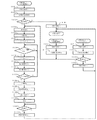
図1に示すように、本実施形態に係る充電装置Aは、この充電装置Aに接続(実装)された充電電池2を充電する。充電電池2(2次電池、電池パック等とも言われる。)は、直列に接続された充電可能な複数の素電池(セル)からなる素電池群2Aと、サーミスタ等によって構成され、素電池群2Aに接触又は近接して配置された温度検出素子2Bと、を備える。温度検出素子2Bは、素電池群2Aの温度を検出するための素子である。充電電池2は、例えば、リチウムイオン2次電池である。各素電池は約3.6Vの電圧を有するリチウムイオン電池であり、素電池群2Aは、このリチウムイオン電池を4個直列に接続したものであり、充電電池2は約14.4Vの電圧を有する。充電電池2は、ニッケル・カドミウム電池、ニッケル水素電池等であってもよい。
As shown in FIG. 1, the charging device A according to the present embodiment charges a
充電装置Aは、第1の整流平滑回路10と、スイッチング回路20と、第2の整流平滑回路30と、電流検出部3と、電池電圧検出部40と、制御部50と、充電電流制御部60と、定電圧電源70と、電源起動部80と、電池温度検出部90と、待機用電源回路100と、充電制御信号伝達部4と、充電電流信号伝達部5と、充電電流設定部6と、定電圧伝達部7と、リセットIC8と、停止信号伝達部9と、充電電池検出部13と、報知回路14と、を備える。
The charging device A includes a first rectifying / smoothing circuit 10, a
第1の整流平滑回路10は、全波整流回路11と、この全波整流回路11に接続された平滑用コンデンサ12とを備える。全波整流回路11は、充電装置Aの外部の交流電源1に接続される。交流電源1は、この第1の整流平滑回路10に電力(充電電圧及び充電電流)を供給する。交流電源1は、例えば、商用電源である。第1の整流平滑回路10は、交流電源1から供給される電力を全波整流及び平滑化する回路である。
The first rectifying / smoothing circuit 10 includes a full-wave rectifying
スイッチング回路20は、高周波トランス(降圧トランス)21と、高周波トランス21の1次コイルに直列接続されたMOSFET(スイッチング素子)22と、MOSFET22のゲート電極に印加する駆動パルス信号のパルス幅を変調させるPWM制御IC(駆動信号制御部)23とを備える。スイッチング回路20には、第1の整流平滑回路10を介して充電装置Aの外部の交流電源1から電力が供給される。
The
PWM制御IC23は、後述の充電電流信号伝達部5から供給される充電電流信号に基づいてMOSFET22のゲート電極に供給する駆動パルス幅を変え、MOSFET22のオン時間を制御し、交流電源1から供給される電力について、後述の第2の整流平滑回路30の出力電圧と充電電池2の充電電流とを調整する。
The
第2の整流平滑回路30は高周波トランス21の2次コイル側に接続されたダイオード31及び32と、ダイオード31及び32に接続されたチョークコイル33と、ダイオード32及びチョークコイル33に接続された平滑コンデンサ34から成る。第2の整流平滑回路30は、スイッチング回路20から供給される電力を整流及び平滑化する回路である。
The second rectifying /
本実施形態では、スイッチング回路20と、第2の整流平滑回路30とが、充電装置Aの外部から供給された電力を用いて充電電池2の充電を行う第1電源回路を構成する。
In the present embodiment, the
ここで、充電装置Aの外部から供給された電力とは、本実施形態のように、第1の整流平滑回路10によって整流及び平滑化された電力等、外部からの電力を所定の方法で変換した電力であってもよい。 Here, the electric power supplied from the outside of the charging device A is a predetermined method for converting the electric power from the outside such as the electric power rectified and smoothed by the first rectifying and smoothing circuit 10 as in the present embodiment. May be the power.
第1の整流平滑回路10とスイッチング回路20と第2の整流平滑回路30とは、交流電源1の電圧を所望の電圧に変換する。例えば、交流電源1として電圧が100Vの商用交流電源を用いた場合、この電圧が印加される第1の整流平滑回路10から得られる電圧は約140V、第2の整流平滑回路30の出力電圧は最大で約16Vとなる(充電電池2が14.4Vのリチウムイオン2次電池の場合)。例えば、交流電源1として電圧が230Vの商用交流電源を用いた場合、この電圧が印加される第1の整流平滑回路10から得られる電圧は約320V、第2の整流平滑回路30の出力電圧は最大で約16Vとなる(充電電池2が14.4Vのリチウムイオン2次電池の場合)。
The first rectifying / smoothing circuit 10, the switching
電流検出部3は、抵抗によって構成され、充電電池2に流れる充電電流を検出するのに用いられる。電流検出部3は、一端が充電電池2に接続され、他端が第2の整流平滑回路30と後述の充電電流制御部60とに接続される。
The
電池電圧検出部40は、直列に接続された抵抗41,42を備える。電池電圧検出部40は、一端が充電電池2と接続され、充電電池2の電圧を検出するのに用いられる。電池電圧検出部40の抵抗41,42によって、充電電池2の端子電圧は分圧される。電池電圧検出部40は、分圧された電圧値に対応する検出信号(充電電池2の充電電圧の検出信号)を、後述のA/Dコンバータ55に供給する。後述の制御部50は、この検出信号によって、充電電池2の充電状態、特に、所定の充電状態(例えば、満充電状態、充電ができない状態)を検出できる。本実施形態では、電池電圧検出部40が充電電池2の所定の充電状態を検出するための検出部を構成する。
The battery
電池温度検出部90は、充電電池2(素電池群2A)の温度を検出するためのものである。電池温度検出部90は、一端が互いに接続された抵抗91、92を備える。抵抗91は、5Vの定電圧源(後述の第2電源回路)と接続され、抵抗91と抵抗92とには温度検出素子2Bが接続される。電池温度検出部90は、抵抗91と抵抗92及び温度検出素子2Bの抵抗とによって分圧された電圧値(充電電池2の温度に対応した値になる)に対応する検出信号(充電電池2の温度の検出信号)を後述のA/Dコンバータ55に供給する。制御部50は、この検出信号によって、充電電池2の充電状態、特に、所定の充電状態(例えば、満充電状態、充電ができない状態)を検出できる。本実施形態では、電池温度検出部90も充電電池2の所定の充電状態を検出するための検出部を構成する。
The battery temperature detection unit 90 is for detecting the temperature of the rechargeable battery 2 (unit cell group 2A). The battery temperature detection unit 90 includes
充電電池2の所定の充電状態を検出するための検出部は、電池電圧検出部40と電池温度検出部90とのうちのいずれか一方を用いるものであってもよい。
The detection unit for detecting a predetermined charging state of the
第1電源回路は、充電電流制御部60が接続されている。充電電流制御部60は、演算増幅器61及び62と、入力抵抗63及び65と、帰還抵抗64及び66とから構成された演算増幅回路を含む。 A charging current control unit 60 is connected to the first power supply circuit. The charging current control unit 60 includes an operational amplifier circuit composed of operational amplifiers 61 and 62, input resistors 63 and 65, and feedback resistors 64 and 66.
入力側に入力抵抗63が配置され、この入力抵抗63に演算増幅器61の反転入力端子が接続される。また、帰還抵抗64は、演算増幅器61の出力端子と反転入力端子とに接続される。また、演算増幅器61の非反転入力端子は接地される。入力抵抗65は、演算増幅器61の出力端子と、演算増幅器62の非反転入力端子とに接続される。帰還抵抗66は、演算増幅器62の出力端子と非反転入力端子とに接続される。 An input resistor 63 is arranged on the input side, and the inverting input terminal of the operational amplifier 61 is connected to the input resistor 63. The feedback resistor 64 is connected to the output terminal and the inverting input terminal of the operational amplifier 61. The non-inverting input terminal of the operational amplifier 61 is grounded. The input resistor 65 is connected to the output terminal of the operational amplifier 61 and the non-inverting input terminal of the operational amplifier 62. The feedback resistor 66 is connected to the output terminal and the non-inverting input terminal of the operational amplifier 62.
この充電電流制御部60の入力側は電流検出部3に接続される。また、その出力側は充電電流信号伝達部5を介してPWM制御IC23に接続される。ここで、充電電流信号伝達部5は、信号を伝達する素子であり、フォトカプラ等から構成される。
The input side of the charging current control unit 60 is connected to the
更に、演算増幅器62の反転入力端子には充電電流設定部6が接続される。充電電流設定部6は、後述する出力ポート56aからの制御信号に対応した電圧値(充電電流設定基準値)を演算増幅器62の反転入力端子に印加(供給)する。充電電流設定基準値は、充電電流の上限値を特定するものであり、充電電池の種類に応じて設定され、充電開始後には変更されない。 Further, the charging current setting unit 6 is connected to the inverting input terminal of the operational amplifier 62. The charging current setting unit 6 applies (supplies) a voltage value (charging current setting reference value) corresponding to a control signal from an output port 56a described later to the inverting input terminal of the operational amplifier 62. The charging current setting reference value specifies an upper limit value of the charging current, is set according to the type of the charging battery, and is not changed after the charging is started.
充電電流制御部60は、電流検出部3を用いて充電電流を検出し、検出した充電電流に対応する電圧と充電電流設定基準値との差を充電電流信号(充電電流を制御するための制御信号)として充電電流信号伝達部5を介してPWM制御IC23に出力する。
The charging current control unit 60 detects the charging current using the
制御部50は、例えば、マイクロコンピュータから成る。制御部50は、制御プログラムを実行して所定の処理を行うCPU(Central Processing Unit)51と、制御プログラム等を格納するROM(Read Only Memory)52と、CPU51の作業領域及びデータの一時記憶領域などとして利用されるRAM(Random Access Memory)53と、タイマ54と、充電電池2の充電電圧の検出信号及び充電電池2の温度の検出信号についてアナログ信号からデジタル信号に変換するA/Dコンバータ55と、制御信号を供給する出力ポート56a、56b、56c、56dと、定電圧電源70から電源が供給された場合、リセット信号が供給されるリセット入力ポート57と、を含む。これらの各要素は内部バスによって相互に接続されている。制御部50は、後述の第1乃至第3動作を行う。制御部50は、他の構成であっても良い。
The control unit 50 is composed of, for example, a microcomputer. The control unit 50 includes a central processing unit (CPU) 51 that executes a control program and performs predetermined processing, a read only memory (ROM) 52 that stores a control program, a work area of the CPU 51, and a temporary storage area for data. A random access memory (RAM) 53, a timer 54, an A / D converter 55 that converts a detection signal of the charging voltage of the charging
CPU51は、制御プログラムに従って、充電電池2の充電の開始又は停止を指示する制御信号(充電制御信号)を、出力ポート56aから充電制御信号伝達部4を介してPWM制御IC23の制御入力端子に供給する。充電制御信号が、PWM制御IC23(スイッチング回路20)に供給されると、PWM制御IC23は所定の動作を行う。これによって、スイッチング回路20は充電の開始又は停止(第1電源回路の動作の開始又は停止)を制御する。充電制御信号伝達部4は、信号を伝達する素子によって構成され、フォトカプラ等からなる。
The CPU 51 supplies a control signal (charging control signal) instructing start or stop of charging of the
CPU51は、例えば、最新の電池電圧(充電電池2の充電電圧の検出信号によって検出できる。)及び最新の電池温度(充電電池2の温度の検出信号によって検出できる。)とRAM53に記憶したサンプリング時間前にサンプリングした複数の電池電圧及び複数の電池温度とから電池電圧勾配及び電池温度勾配の演算等を行う。
For example, the CPU 51 can detect the latest battery voltage (which can be detected by a detection signal of the charging voltage of the rechargeable battery 2), the latest battery temperature (which can be detected by a detection signal of the temperature of the rechargeable battery 2), and the sampling time stored in the
CPU51は、所望のタイミングで、出力ポート56dから待機用電源回路100を動作又は停止させる制御信号(待機用電源制御信号)を待機用電源回路100に供給する。 The CPU 51 supplies the standby power supply circuit 100 with a control signal (standby power supply control signal) for operating or stopping the standby power supply circuit 100 from the output port 56d at a desired timing.
定電圧電源70は、トランス71と、トランス71の1次コイル側にコレクタが接続されたスイッチングトランジスタ72と、トランス71の補助コイル711に接続された整流ダイオード79及び平滑コンデンサ78から成る動作電圧供給回路と、スイッチングトランジスタ72のベース端子に接続された定電圧制御部(ベース駆動制御部)77とを備え、更にトランス71の2次コイル側には、整流ダイオード710と、平滑コンデンサ74及び75と、3端子レギュレータ73とから成る電源出力回路を備える。また、定電圧電源70は、フォトカプラ等の信号伝達素子によって構成された定電圧伝達部76を備える。定電圧伝達部76は、電源出力回路に接続され、トランス71の2次コイル側の整流ダイオード710を通して整流された電圧を定電圧制御部77に伝達する。
The constant
定電圧制御部77は、定電圧電源70の制御部に相当し、第1の整流平滑回路10から入力Vccに電力が供給される。第1の整流平滑回路10から定電圧制御部77に一旦電力が供給されると、定電圧制御部77は、定電圧伝達部76から供給された信号(整流ダイオード710を通して整流された電圧を表す信号)に基づいて、平滑コンデンサ74の両端電圧が所定の電圧となるようにスイッチングトランジスタ72をスイッチング動作させる。一旦スイッチング動作が開始すると、トランス71の補助コイル711に発生した電圧が整流ダイオード79、平滑コンデンサ78を介して定電圧制御部77の入力Vccに印加されるので、定電圧電源70は入力Vccへの第1の整流平滑回路10からの電力の供給が停止しても(電源起動部80が停止しても)動作する。
The constant
一方、定電源電圧70のトランス71側には第1の整流平滑回路10からの電力が引き続き供給され、トランス71の2次コイル側の整流ダイオード710を通して整流された電圧が定電圧伝達部76を介して定電圧制御部77に帰還され、定電圧制御部77の出力電圧が所定のパルス幅を持つように制御され、これに基づくスイッチングトランジスタ72のスイッチング動作により、整流ダイオード710と、平滑コンデンサ74及び75と、3端子レギュレータ73とから成るトランス71の2次コイル側電源出力回路は、所定の定電圧Vcを出力する。この定電圧Vcは、例えば、5Vの電圧である。この定電圧Vcは制御部50、充電電流制御部60、リセットIC8、及び電池温度検出部90等に印加され、定電圧電源70はこれらの電源になる。
On the other hand, the power from the first rectifying / smoothing circuit 10 is continuously supplied to the transformer 71 side of the constant
本実施形態では、定電圧電源70が、充電装置Aの外部から供給された電力を用いて制御部50に電力を供給する第2電源回路を構成する。
In the present embodiment, the constant
定電圧電源70の出力にはリセットIC8が接続されている。定電圧電源70が動作すると、この停電源電圧70からリセットIC8に電圧(5V)が印加され、リセットIC8はリセット信号を制御部50の入力ポート57に供給する。リセット入力ポート57(制御部50)に供給されたリセット信号によって、制御部50はリセットされる。
A reset IC 8 is connected to the output of the constant
停止信号伝達部9は、出力ポート56bと定電圧制御部77とに接続され、出力ポート56bから供給される制御信号(停止信号)を定電圧制御部77に伝達する。停止信号が定電圧制御部77に供給されると、定電圧制御部77は定電圧電源70全体の動作(電力の供給)を停止させる。これによって、充電装置Aの動作も停止する。制御部50は、所定のタイミング(詳しくは後述する)に停止信号を停止信号伝達部9を介して定電圧制御部77に供給する。停止信号伝達部9は、フォトカプラ等の信号伝達素子によって構成される。
The stop
電源起動部80は、スイッチ81と、抵抗82と、スイッチ素子83と、コンデンサ84とを備える。スイッチ81と、スイッチ素子83と、コンデンサ84とは並列に接続され、抵抗82は、これらと直列に接続される。 The power supply activation unit 80 includes a switch 81, a resistor 82, a switch element 83, and a capacitor 84. The switch 81, the switch element 83, and the capacitor 84 are connected in parallel, and the resistor 82 is connected in series with them.
電源起動部80は、第1の整流平滑回路10と定電圧制御部77(入力電圧Vcc)に接続され、スイッチ81又はスイッチ素子83のオンにより、交流電源1からの電力(第1の整流平滑回路10が出力する電力)を定電圧電源70に一時的に供給して、定電圧電源70を動作状態にする起動回路である。通常、スイッチ81は外部からオンされない限りオフとなる。スイッチ81は、外部から操作されて一定期間オンになる。またスイッチ素子83は、充電電池検出部13からの信号(充電電池検出信号)が供給されている間、オンする。
The power source starting unit 80 is connected to the first rectifying / smoothing circuit 10 and the constant voltage control unit 77 (input voltage Vcc), and the power (first rectifying / smoothing) from the AC power source 1 is turned on when the switch 81 or the switch element 83 is turned on. This is a start-up circuit that temporarily supplies the electric power output from the circuit 10 to the constant
ここで、充電電池検出部13は、コンデンサ131と抵抗132との直列回路を含み、充電電池2が充電装置Aに接続されたことを検出するためのものである。充電電池検出部13は、充電電池2が充電装置Aに取り付けられたときに、この取り付け時から一定期間の間、充電電池検出信号を出力する微分回路で構成される。また、充電電池検出部13は、無効電力が発生しないように構成される。充電電池検出信号は、充電電池検出伝達部7を介して、電源起動部80のスイッチ素子83に供給される。充電電池検出伝達部7は、信号を伝達する素子によって構成され、フォトカプラ等からなる。
Here, the rechargeable battery detection unit 13 includes a series circuit of a capacitor 131 and a resistor 132 and detects that the
また、コンデンサ84と抵抗82とが微分回路を構成することにより、電源起動部80は、交流電源1が接続された時(接続開始時)にのみ一定の期間だけ定電圧電源70に交流電源1からの電力(第1の整流平滑回路10が出力する電力)を供給することにより定電圧電源70を動作状態にする起動回路にもなる。
In addition, since the capacitor 84 and the resistor 82 constitute a differentiation circuit, the power source activation unit 80 is connected to the constant
上記のように、電源起動部80は、定電圧電源70を動作状態にするので充電装置Aを動作状態にする、つまり、充電装置Aを起動することになる。電源起動部80は、交流電源1の接続開始時、スイッチ81がオンされた時、及び、充電電池2が実装された時にのみ、一定期間動作し(一定期間、第1の整流平滑回路10からの電力を定電圧電源70に供給し)、それ以外の時には無効電力が発生しない構成にしている。
As described above, the power supply activation unit 80 brings the constant
待機用電源回路100は、DC/DCコンバータ制御IC101と、DC/DCコンバータ制御IC101にベース端子が接続されたトランジスタ102と、トランジスタ102に接続されたチョークコイル103と、DC/DCコンバータ制御IC101及びチョークコイル103に接続されたダイオード104,105と、を備える。
The standby power supply circuit 100 includes a DC / DC
待機用電源回路100は、充電装置Aに取り付けられた充電電池2に接続され、この充電電池2から供給される電力で制御部50を動作させる。つまり、本実施形態では、待機用電源回路100が、制御部50に必要な電力を充電電池2から制御部50に供給する電力供給部を構成する。
The standby power supply circuit 100 is connected to the
待機用電源回路100は、制御部50の出力ポート56dからの待機用電源制御信号に応じて充電電池2から電力を制御部50に供給又は供給の停止をする。例えば、DC/DCコンバータ制御IC101に待機用電源制御信号が供給されると、DC/DCコンバータ制御IC101が動作又は停止し、待機用電源回路100は、充電電池2から制御部50への電力の供給を開始又は停止する。
The standby power supply circuit 100 supplies power from the
待機用電源回路100は、DC/DCコンバータ制御IC101で出力電圧(ダイオード105のカソード側)が所定値(ここでは5V)になるようにトランジスタ102のスイッチングパルス幅を制御するチョーパー方式のDC/DCコンバータによって構成されている。しかし、待機用電源回路100は、これに限られるものではなく、例えば、3端子レギュレータ又は抵抗とツェナーダイオード等とを含む簡単な電源回路によって構成されてもよい。充電電池2のエネルギーで制御部50へ電力供給を行うので、待機用電源回路100は、低消費電力、高効率な電源回路が望ましい。
The standby power supply circuit 100 uses a DC / DC
報知回路14は、直列に接続した抵抗141、LED142を備え、出力ポート56cから制御信号(報知制御信号)が供給されると、充電電池2が所定の充電状態になっていることをユーザ等に報知するための回路である。報知回路14は、主に充電装置Aに接続された充電電池2の満充電を知らせる回路となる。ここでは、報知回路14は、報知制御信号の供給によるLED142の発光によって、所定の充電状態を報知するが、報知回路14は、LED142の代わりに圧電ブザー又は液晶表示素子等を備える回路であってもよい。圧電ブザーや液晶等によって更に低消費電力化が可能となることもある。本実施形態では、報知回路14が、充電電池2が所定の充電状態にあることを報知するための報知部となる。
The
以上の回路構成により、交流電源1の投入、スイッチ81のオン、又は、充電電池2の充電装置Aへの実装により、定電圧電源70は動作を開始し、充電装置Aが動作する。そして、充電電池2が所定の充電状態になって充電が終了した後に、制御部50は、定電圧電源70の動作を停止させる。そして、このとき、制御部50は、待機用電源回路100の動作を開始させて、充電電池2からの電力で動作する。これによって、制御部50は、定電圧電源70の動作が停止しても充電電池2の電力によって動作する。制御部50は、充電電池2の電力によって動作し、充電電池2の充電状態(例えば満充電)を報知回路14を用いて知らせる事で、交流電源1についての消費電力(外部から供給される電力の消費)がゼロ又は少ない状態で、充電電池2の所定の充電状態を知らせる事が可能となる。
With the above circuit configuration, the constant
次に充電装置Aが行う充電処理について説明する(特に図2参照)。 Next, a charging process performed by the charging device A will be described (particularly, refer to FIG. 2).
充電装置Aに交流電源1が接続されると、まず電源起動部80の抵抗82及びコンデンサ84からなる微分回路により定電圧電源70がオンする(ステップS101)。つまり、定電圧電源70が動作状態になる。
When the AC power source 1 is connected to the charging device A, first, the constant
定電圧電源70が起動すると、次いで制御部50等が動作を開始する(ステップS102)。具体的には、定電圧電源70が起動すると、定電圧電源70からの電力供給が開始され、リセットIC8はリセット入力ポート57(制御部50)にリセット信号を供給する。これによって、制御部50はリセットされ、CPU51がROM52内の制御プログラムに従って制御部50が行う処理を開始する。
When the constant
次に、制御部50は、充電電池2が充電装置Aに接続されているかの判別を行う(ステップS103)。制御部50は、この判定を、例えば、電池温度検出部90を用いて行う。充電電池2が充電装置Aに取り付けられていると、制御部50側から見て、温度検出素子2Bと抵抗92とが並列の接続関係になっている。このため、電池温度検出部90が供給する検出信号に対応する電圧値は、抵抗91と抵抗92とで分圧された電圧値ではなくなる。つまり、温度検出素子2Bと抵抗92とが並列に接続されることに対応した検出信号がA/Dコンバータ55(つまり、制御部50)に入力される。
Next, the control unit 50 determines whether the
制御部50は、例えば、制御部50に入力される検出信号(A/Dコンバータ55で変換されたデジタル信号)が示す電圧値が、所定の基準を満たすか否か(温度検出素子2Bと抵抗92とが並列に接続されることに対応した電圧値であるか否か)で上記の判別を行うことができる。また、制御部50は、充電電池検出部13を用いて上記の判別を行っても良い。この場合、充電電池検出部13が充電電池検出信号を制御部50にも供給するように充電装置Aは構成される。 For example, the control unit 50 determines whether or not the voltage value indicated by the detection signal (digital signal converted by the A / D converter 55) input to the control unit 50 satisfies a predetermined standard (temperature detection element 2B and resistance). The above determination can be made based on whether or not the voltage value corresponds to the fact that 92 is connected in parallel. Further, the control unit 50 may perform the above determination using the rechargeable battery detection unit 13. In this case, the charging device A is configured such that the charging battery detection unit 13 also supplies the charging battery detection signal to the control unit 50.
制御部50は、例えば、上記の検出信号が示す電圧値が所定の基準を満たすことによって、充電電池2の接続があると判別すると(ステップS103;Yes)、つまり、充電装置Aの電源である交流電源1が充電装置Aに接続され、充電装置Aが動作を開始し、充電電池2が実装されている場合、制御部50は、ステップS130の処理を行う。
For example, if the control unit 50 determines that the
一方、制御部50は、例えば、上記の検出信号が示す電圧値が所定の基準を満たさないことによって、充電電池2が充電装置Aに接続していないと判別すると(ステップS103;No)、制御部50は、定電圧電源70を停止させる(ステップS104)。制御部50は、充電装置Aの消費電力を抑えるように定電圧電源70の動作を停止させるための停止信号を、出力ポート56bより停止信号伝達部9を介して定電圧制御部77に供給する。停止信号が定電圧制御部77に供給されると、定電圧電源70は停止する。
On the other hand, for example, when the control unit 50 determines that the
この場合(ステップS103;No)、充電装置Aの電源である交流電源1が投入され、充電装置Aは動作を開始したが、充電電池2が未実装であり、消費電流を抑えるために完全に充電装置Aの動作は停止する(充電処理終了)。つまり、充電装置Aは消費電力がゼロ(ゼロは、適宜略ゼロも含む。以下同じ)になる。次いで、動作が停止した充電装置Aは、外部からのアクセスによる動作の再開を待つ。
In this case (step S103; No), the AC power source 1 that is the power source of the charging device A is turned on, and the charging device A starts to operate, but the
外部からのアクセスの1つは、充電電池2が充電装置Aに接続された場合である(充電電池接続)。このとき、充電装置Aは交流電源1に接続されているものとする。充電電池2が充電装置Aに接続されると、充電電池検出部13は、充電電池検出伝達部7を介して、充電電池検出信号を電源起動部80のスイッチ素子83に一定期間供給する。スイッチ素子83に充電電池検出信号が供給されると、定電圧電源70がオンする(ステップS111)。つまり、電源起動部80は定電圧電源70を動作状態にする(起動する)。
One access from the outside is when the
次に、定電圧電源70が起動すると、次いで制御部50が動作を開始する(ステップS112)。この処理は、ステップS102における処理と同様である。
Next, when the constant
更にもう1つの外部からのアクセスとして、電源起動部80のスイッチ81のオンがある(スイッチオン)。このときも、充電装置Aは交流電源1に接続されているものとする。電源起動部80のスイッチ81がオンすれば、電源起動部80は定電圧電源70をオンさせ動作状態にし(ステップS121)、制御部50は動作を開始する(ステップS122)。次に制御部50は充電電池2が接続されているかの判別を行う(ステップS123)。ここで、ステップS122及びステップS123の処理は、ステップS102及びステップS103の処理と同様である。
Still another external access is turning on the switch 81 of the power activation unit 80 (switch on). Also at this time, the charging device A is assumed to be connected to the AC power source 1. If the switch 81 of the power supply starter 80 is turned on, the power supply starter 80 turns on the constant
制御部50は、充電電池2が充電装置Aに接続されていないと判別すると(ステップS123;No)、定電圧電源70をオフ(動作を停止)し(ステップS124)、充電装置Aは完全な停止状態となる(充電装置停止)。ここで、ステップS124の詳細は、ステップS104と同様である。
When determining that the
なお、スイッチ81は、ユーザが操作可能なスイッチとするために充電装置Aの外部に露出するスイッチである。このスイッチ81の利用は、充電電池2が完全な0V又は略0V電池(残エネルギーがゼロの電池)であった場合に前記で説明した充電電池2の実装で動作する微分回路(充電電池検出部13)が動作できないので、このような状況を踏まえ準備したものであり、通常使用においては、被充電電池が0Vになるような状況はまれであるので、スイッチ81はあまり使われない。
Note that the switch 81 is a switch exposed to the outside of the charging apparatus A so as to be a switch operable by the user. The switch 81 is used when the
次に制御部50は、ステップS130において、充電を開始するために、充電電流設定基準値を充電電流設定部6に設定する(ステップS130)。具体的には、制御部50は、出力ポート56aから所定の制御信号を充電電流設定部6に供給する。充電電流設定部6は、この制御信号に応じて所定の充電電流設定基準値を設定し、設定した充電電流設定基準値を演算増幅器62に印加(充電電流制御部60に供給)する。 Next, in step S130, the control unit 50 sets a charging current setting reference value in the charging current setting unit 6 in order to start charging (step S130). Specifically, the control unit 50 supplies a predetermined control signal to the charging current setting unit 6 from the output port 56a. The charging current setting unit 6 sets a predetermined charging current setting reference value according to the control signal, and applies the set charging current setting reference value to the operational amplifier 62 (supplied to the charging current control unit 60).
次に制御部50は、出力ポ−ト56aから充電制御信号伝達部4を介してPWM制御IC23に充電制御信号(充電開始信号)を伝達する。これによって、スイッチング回路20は充電の開始の制御を行い、充電装置A(第1電源回路)は充電を開始する(ステップ131)。
Next, the control unit 50 transmits a charge control signal (charge start signal) from the output port 56 a to the
充電開始と同時に、充電電流制御部60は、充電電池2に流れる充電電流を電流検出部3により検出し、この充電電流に対応する電圧と充電電流設定基準値(演算増幅器62の反転入力端子に印加された電圧値)との差(充電電流信号)を充電電流信号伝達部5を介してPWM制御IC23に帰還する。PWM制御IC23は、充電電流が大きい場合はパルス幅を狭めたパルスを、逆の場合はパルス幅を広げたパルスをMOSFET22を介して高周波トランス21に与え、第2の整流平滑回路30は、スイッチング回路20から供給される電力を直流にして平滑し(整流及び平滑化し)、充電電流を一定に保つ。電流検出部3、充電電流制御部60、充電電流信号伝達部5、スイッチング回路20、第2の整流平滑回路30は、充電電流が一定になるように動作する。
Simultaneously with the start of charging, the charging current control unit 60 detects the charging current flowing through the
次に、制御部50は、充電中の電池電圧、電池温度等の情報を一定間隔毎に取り込むためにタイマ54をスタートさせ(ステップS132)、タイマ54のスタートからの経過時間を計測し(ステップS133)、サンプリング期間が到来するまで経過時間を計測する(ステップS133;No)。制御部50は、タイマ54が計測する経過時間がサンプリング期間になると、つまり、サンプリング期間が到来したら(ステップS133;Yes)、再度タイマ54をスタートさせる(ステップ134)。 Next, the control unit 50 starts the timer 54 to capture information such as the battery voltage and battery temperature during charging at regular intervals (step S132), and measures the elapsed time from the start of the timer 54 (step S132). S133), the elapsed time is measured until the sampling period arrives (step S133; No). When the elapsed time measured by the timer 54 becomes the sampling period, that is, when the sampling period comes (step S133; Yes), the control unit 50 starts the timer 54 again (step 134).
次いで、制御部50は、電池温度検出部90から供給される充電電池2の温度の検出信号をもとに、充電電池2の電池温度を取り込む(ステップ135)。さらに、制御部50は、電池電圧検出部40から供給される充電電池2の充電電圧の検出信号をもとに、充電電池2の電池電圧を取り込む(ステップ136)。制御部50は、ここで検出した電池温度及び電池電圧をRAM53にサンプリング期間ごとに記録し、RAM53に記録された電池温度及び/又は電池電圧はステップS137の所定の充電状態判別処理に用いる。
Next, the control unit 50 takes in the battery temperature of the
制御部50は、RAM53に記録された電池温度及び/又は電池電圧を用いて、充電電池2が所定の充電状態になったかを判別する(ステップS137)。所定の充電状態とは例えば満充電状態、充電電池2の異常等である。
The control unit 50 determines whether or not the
満充電状態の判別は、周知の如く種々の検出方法がある。例えば、電池電圧が、充電末期のピーク電圧から所定量降下したことを検出して満充電状態であると判別する周知の−ΔV検出方法がある。 As is well known, there are various detection methods for determining the fully charged state. For example, there is a known -ΔV detection method for detecting that the battery voltage has fallen by a predetermined amount from the peak voltage at the end of charging and determining that the battery is fully charged.
例えば、電池電圧がピークに達する前に充電を停止することにより過充電を低減し、充電電池2のサイクル寿命を向上させることを目的とした2階微分検出法であって、電池電圧と時間とによる2階微分値が負になるのを検出して満充電状態であると判別する2階微分検出法がある。
For example, a second-order differential detection method aimed at reducing overcharge by stopping charging before the battery voltage reaches a peak and improving the cycle life of the
例えば、充電開始からの充電電池2の温度上昇値が所定の温度上昇値以上になるのを検出して満充電状態であると判別するΔT検出法がある。
For example, there is a ΔT detection method for detecting that the temperature rise value of the
例えば、特開昭62−193518号公報、特開平2−246739号公報、実開平3−34638号公報等に記載されている充電時における所定時間当りの電池温度上昇率(温度勾配)が所定値以上になるのを検出して満充電状態であると判別するdT/dt検出法がある。 For example, the battery temperature increase rate (temperature gradient) per predetermined time during charging described in JP-A-62-193518, JP-A-2-24639, JP-A-3-34638, etc. is a predetermined value. There is a dT / dt detection method in which it is determined that the battery is fully charged by detecting the above.
また、所定の充電状態が充電電池2の異常である場合、制御部50は、上記の方法を利用して、例えば、温度の異常な上昇を検出して、充電電池2の異常であると判別してもよい。
When the predetermined charging state is an abnormality of the
制御部50は、上記一つないし複数の方法を用いて充電状態判別処理(ステップS137)を行う。 The controller 50 performs the state of charge determination process (step S137) using one or more of the above methods.
ステップS137の処理において、制御部50は、充電電池2が所定の充電状態でないと判別すると(ステップS137;No)、ステップS133の処理に戻る。このようにして、制御部50は、充電電池2が所定の充電状態になるまで、ステップS133乃至ステップS136の処理を繰り返し行う。
In the process of step S137, when the control unit 50 determines that the
ステップS137の処理において、制御部50は、充電電池2が所定の充電状態であると判別すると(ステップS137;Yes)、出力ポ−ト56aから充電制御信号伝達部4を介してPWM制御IC23に充電制御信号(充電停止信号)を伝達する。これによって、スイッチング回路20は充電の停止の制御を行い、充電装置A(第1電源回路)は充電を停止する(ステップS138)。充電装置Aは、交流電源1から供給される電力の消費をゼロになるようにしている。
In the process of step S137, when the control unit 50 determines that the
次に制御部50は、出力ポート56dからDC/DCコンバータ制御IC101に、待機用電源回路100を動作させるための待機用電源制御信号(オン信号)を供給し、DC/DCコンバータ制御IC101を動作させ、待機用電源回路100をオンさせ、待機用電源回路100に充電電池2から制御部50への電力の供給を開始させる(ステップS139)。
Next, the control unit 50 supplies a standby power control signal (ON signal) for operating the standby power supply circuit 100 to the DC / DC
次に、制御部50は、ステップS104の処理と同様の処理によって、交流電源1からのエネルギー(電力)で動作している定電圧電源70を停止させる(ステップS140)。これによって、制御部50は、充電電池2をエネルギー源(電力供給源)とする待機用電源回路100を電源として動作する。また、定電圧電源70が停止したことによって、交流電源1からの電力供給は停止し、交流電源からの電力の消費はゼロになる。すなわち、充電電池2を充電しているとき以外は、充電装置Aにおける交流電源1についての消費電力(外部から供給される電力の消費)はゼロである又は少ない。
Next, the control unit 50 stops the constant
次に、制御部50は、出力ポート56cから報知制御信号を報知回路14に供給し、充電電池2が所定の充電状態になったことをユーザ等に報知する(ステップS141)。報知回路14は、例えば、満充電に対応するLEDの発光、又は、充電電池2の異常に対応するLEDの発光等によって所定の充電状態を報知する。
Next, the control unit 50 supplies a notification control signal to the
次に、制御部50は、充電電池2が充電装置Aから外されたかを判別する(ステップ142)。
Next, the control unit 50 determines whether or not the
制御部50は、この判別を、例えば、電池温度検出部90を用いて行う。充電電池2が充電装置Aから外されると、電池温度検出部90が供給する検出信号に対応する電圧値は、抵抗91と抵抗92とで分圧された電圧値となる。つまり、抵抗91と抵抗92とで分圧された電圧値に対応する検出信号がA/Dコンバータ55(つまり、制御部50)に入力される。
The control unit 50 performs this determination using, for example, the battery temperature detection unit 90. When the
制御部50は、例えば、制御部50に入力される検出信号(A/Dコンバータ55で変換されたデジタル信号)が示す電圧値が、所定の基準を満たすか否か(抵抗91と抵抗92とで分圧された電圧値であるか否か)で上記の判別を行うことができる。また、制御部50は、充電電池検出部13を用いて上記の判別を行っても良い。この場合、充電電池検出部13が充電電池検出信号を制御部50にも供給するように充電装置Aは構成される。 For example, the control unit 50 determines whether or not the voltage value indicated by the detection signal (digital signal converted by the A / D converter 55) input to the control unit 50 satisfies a predetermined standard (the resistors 91 and 92). The above determination can be made based on whether or not the voltage value is divided by. Further, the control unit 50 may perform the above determination using the rechargeable battery detection unit 13. In this case, the charging device A is configured such that the charging battery detection unit 13 also supplies the charging battery detection signal to the control unit 50.
制御部50は、例えば、上記の検出信号が示す電圧値が所定の基準を満たすことによって、充電電池2が充電装置Aから外されたと判別するまで、ステップS142の処理を繰り返す(ステップS142;No)。また、制御部50は、充電電池2が充電装置Aから外されたと判別すると(ステップS142;Yes)、出力ポート56dから待機用電源回路100を停止するための待機用電源制御信号(オフ信号)を待機用電源回路100に供給し、待機用電源回路100の動作を停止(待機用電源回路100をオフ)させる(ステップS143)。待機用電源回路100が停止すると、充電装置Aの動作は完全に停止し、充電装置Aは外部からのアクセスを待つことになる(充電処理終了)。
For example, the control unit 50 repeats the process of step S142 until it is determined that the
以上のように、充電装置Aは、動作停止状態つまり電気的に消費がなく待機電力ゼロの状態から、充電電池2の残エネルギーで通常動作状態に回復させ(ごくまれにある残エネルギーがゼロの充電電池2の場合においてはスイッチ81により待機状態から通常動作状態に回復させ)、充電が完了した後、交流電源1に関わる回路の動作(第1電源回路及び第2電源回路)を停止し、交流電源1からの待機電力ゼロの状態となる。また、充電装置Aは、ユーザに充電電池2の所定の充電状態を知らせるために充電電池2のエネルギーを利用し所定の充電状態を報知する。
As described above, the charging device A recovers to the normal operation state with the remaining energy of the
以上で説明したように本実施形態では、制御部50は、電池電圧検出部40及び又は電池温度検出部90によって所定の充電状態を検出する第1動作(ステップS135乃至ステップS137)と、この第1動作で所定の充電状態を検出すると充電電池2が所定の充電状態にあることを報知回路14によって報知する第2動作(ステップS141)とを行う。さらに、第2動作を行う制御部50に供給される電力は、待機用電源回路100を介して充電電池2から供給される。このため、充電装置Aは、報知回路14を動作させるときに、外部から供給される電力を必要としないため、所定の充電状態の報知時に、外部から供給される電力の消費量は少ないか、外部から供給される電力を消費しない。
As described above, in the present embodiment, the control unit 50 performs the first operation (step S135 to step S137) for detecting a predetermined state of charge by the battery
また、制御部50は、スイッチング回路20と第2の整流平滑回路30とによる充電中に、第1動作で所定の充電状態を検出するとスイッチング回路20に前記の充電を停止させる第3動作(ステップS138)をさらに行う(この動作は、第2動作の前に行われるとよい。)。これによって、充電電池2が所定の充電状態になったときに、充電が停止されるので、これ以降に外部から供給される電力(交流電源1から供給される電力)の消費量は少なくなる。
In addition, when the control unit 50 detects a predetermined charging state in the first operation during charging by the switching
また、制御部50は、第2動作を行うときに、定電圧電源70を停止させ、待機用電源回路100を動作させる(ステップS139及びステップS140)。これによって、定電圧電源70の停止後は、制御部50が充電電池2の電力によって動作するので、定電圧電源70の停止後は、外部から供給される電力が停止される。このため、この充電装置Aは外部から供給される電力の消費量が少ないか、外部から供給される電力を消費しない。
Further, when performing the second operation, the control unit 50 stops the constant
制御部50は、待機用電源回路100を動作させてから定電圧電源70を停止させる(ステップS139及びステップS140)。これによって、制御部50が第1動作(及び第3動作)から第2動作へ移行するときに、制御部50への電力の供給が中断されることを防ぎ、制御部50は連続して動作できる。 The control unit 50 operates the standby power supply circuit 100 and then stops the constant voltage power supply 70 (steps S139 and S140). This prevents the supply of power to the control unit 50 from being interrupted when the control unit 50 shifts from the first operation (and the third operation) to the second operation, and the control unit 50 operates continuously. it can.
所定の充電状態は、満充電状態である。これによって、充電装置Aは、充電電池2の満充電後、外部から供給される電力の消費量が少ないか、外部から供給される充電装置Aの電力を消費しない。
The predetermined charging state is a fully charged state. Thereby, after the charging
また、本実施形態に係る充電装置Aは、充電電池2が所定の充電状態にあることを報知する報知手段(制御部50と報知回路14とによって構成される。)を備え、この報知手段は、充電電池2から供給される電力によって動作する。このような充電装置Aは、報知手段による報知のときに、外部から供給される電力を必要としないため、所定の充電状態の報知時に、外部から供給される電力の消費量は少ないか、外部から供給される電力を消費しない。また、この充電装置Aは、充電電池2の所定の充電状態を検出する検出手段(制御部50と電池電圧検出部40及び又は電池温度検出部90とによって構成される。)をさらに備え、前記の報知手段は、前記の検出手段が所定の充電状態を検出すると充電電池2が所定の充電状態にあることを報知する。これによって、報知手段が報知したい所定の充電状態を検出して、ユーザに報知できる。
Moreover, the charging device A according to the present embodiment includes notification means (configured by the control unit 50 and the notification circuit 14) for notifying that the
また、本実施形態に係る充電装置Aと充電電池2とは、充電システムを構成する。
Moreover, the charging device A and the
A 充電装置
2 充電電池
2A 素電池群
2B 温度検出素子
3 電流検出部
4 充電制御信号伝達部
5 充電電流信号伝達部
6 充電電流設定部
7 充電電池検出伝達部
8 リセットIC
9 停止信号伝達部
10 第1の整流平滑回路
11 全波整流回路
12 平滑用コンデンサ
13 充電電池検出部
131 コンデンサ
132 抵抗
14 報知回路
141 抵抗
142 LED
20 スイッチング回路
21 高周波トランス
22 MOSFET
23 PWM制御IC
30 第2の整流平滑回路
31 ダイオード
32 ダイオード
33 チョークコイル
34 平滑コンデンサ
40 電池電圧検出部
41 抵抗
42 抵抗
50 制御部
51 CPU
52 ROM
53 RAM
54 タイマ
55 A/Dコンバータ
56a 出力ポート
56b 出力ポート
56c 出力ポート
56d 出力ポート
57 リセット入力ポート
60 充電電流制御部
61 演算増幅器
62 演算増幅器
63 入力抵抗
64 帰還抵抗
65 入力抵抗
66 帰還抵抗
70 定電圧電源
71 トランス
72 スイッチングトランジスタ
73 3端子レギュレータ
74 平滑コンデンサ
75 平滑コンデンサ
76 定電圧伝達部
77 定電圧制御部
78 平滑コンデンサ
79 整流ダイオード
710 整流ダイオード
80 電源起動部
81 スイッチ
82 抵抗
83 スイッチ素子
84 コンデンサ
90 電池温度検出部
91 抵抗
92 抵抗
100 待機用電源回路
101 DC/DCコンバータ制御IC
102 トランジスタ
103 チョークコイル
104 ダイオード
105 ダイオード
A charging
9 Stop signal transmission unit 10 First
20 switching circuit 21
23 PWM control IC
30 Second rectifying / smoothing
52 ROM
53 RAM
54 Timer 55 A / D Converter 56a Output Port 56b Output Port 56c Output Port 56d Output Port 57 Reset Input Port 60 Charging Current Control Unit 61 Operational Amplifier 62 Operational Amplifier 63 Input Resistance 64 Feedback Resistance 65 Input Resistance 66
102
Claims (8)
前記充電電池が所定の充電状態にあることを報知する報知手段を備え、
前記報知手段は、前記充電電池から供給される電力によって動作する、
ことを特徴とする充電装置。 A charging device for charging a rechargeable battery,
Informing means for informing that the rechargeable battery is in a predetermined state of charge,
The notification means is operated by electric power supplied from the rechargeable battery.
A charging device characterized by that.
前記報知手段は、前記検出手段が前記所定の充電状態を検出すると前記充電電池が前記所定の充電状態にあることを報知する、
ことを特徴とする請求項1に記載の充電装置。 Further comprising detection means for detecting the predetermined state of charge of the rechargeable battery,
The informing means informs that the rechargeable battery is in the predetermined charging state when the detecting means detects the predetermined charging state.
The charging device according to claim 1.
前記充電電池の所定の充電状態を検出するための検出部と、
前記充電電池が前記所定の充電状態にあることを報知するための報知部と、
前記検出部によって前記所定の充電状態を検出する第1動作と前記第1動作で前記所定の充電状態を検出すると前記充電電池が前記所定の充電状態にあることを前記報知部によって報知する第2動作とを行う制御部と、
前記制御部が前記第2動作を行うために必要な電力を前記充電電池から前記制御部に供給する電力供給部と、
を備えることを特徴とする充電装置。 A charging device for charging a rechargeable battery,
A detection unit for detecting a predetermined state of charge of the rechargeable battery;
An informing unit for informing that the rechargeable battery is in the predetermined charging state;
A first operation for detecting the predetermined charging state by the detection unit and a second operation for notifying the charging unit by the notification unit that the charging battery is in the predetermined charging state when the predetermined charging state is detected by the first operation. A control unit for performing operations,
A power supply unit that supplies power necessary for the control unit to perform the second operation from the rechargeable battery to the control unit;
A charging device comprising:
前記制御部は、前記第1動作で前記所定の充電状態を検出すると前記第1電源回路に前記充電を停止させる第3動作をさらに行う、
ことを特徴とする請求項3に記載の充電装置。 A first power supply circuit for charging the rechargeable battery using electric power supplied from the outside of the charging device;
The control unit further performs a third operation for causing the first power supply circuit to stop the charging when the predetermined charging state is detected in the first operation.
The charging device according to claim 3.
前記制御部は、前記第2動作を行うときに、前記第2電源回路を停止させ、前記電力供給部を動作させる、
ことを特徴とする請求項3又は4に記載の充電装置。 A second power supply circuit for supplying power to the control unit using power supplied from outside the charging device;
The control unit, when performing the second operation, stops the second power supply circuit and operates the power supply unit.
The charging device according to claim 3 or 4, characterized in that.
ことを特徴とする請求項5に記載の充電装置。 The control unit stops the second power supply circuit after operating the power supply unit.
The charging device according to claim 5.
ことを特徴とする請求項1乃至6のいずれか1項に記載の充電装置。 The predetermined charging state is a fully charged state.
The charging device according to any one of claims 1 to 6, wherein
前記充電装置が充電する前記充電電池と、
を備えることを特徴とする充電システム。 A charging device according to any one of claims 1 to 7,
The rechargeable battery to be charged by the charging device;
A charging system comprising:
Priority Applications (1)
| Application Number | Priority Date | Filing Date | Title |
|---|---|---|---|
| JP2009228407A JP2011078246A (en) | 2009-09-30 | 2009-09-30 | Charger and charging system |
Applications Claiming Priority (1)
| Application Number | Priority Date | Filing Date | Title |
|---|---|---|---|
| JP2009228407A JP2011078246A (en) | 2009-09-30 | 2009-09-30 | Charger and charging system |
Publications (2)
| Publication Number | Publication Date |
|---|---|
| JP2011078246A true JP2011078246A (en) | 2011-04-14 |
| JP2011078246A5 JP2011078246A5 (en) | 2012-05-17 |
Family
ID=44021623
Family Applications (1)
| Application Number | Title | Priority Date | Filing Date |
|---|---|---|---|
| JP2009228407A Pending JP2011078246A (en) | 2009-09-30 | 2009-09-30 | Charger and charging system |
Country Status (1)
| Country | Link |
|---|---|
| JP (1) | JP2011078246A (en) |
Cited By (5)
| Publication number | Priority date | Publication date | Assignee | Title |
|---|---|---|---|---|
| JP2013021778A (en) * | 2011-07-08 | 2013-01-31 | Sony Corp | Control device, power storage system, electronic apparatus, electric vehicle, and electric power system |
| JP2013070453A (en) * | 2011-09-20 | 2013-04-18 | Panasonic Eco Solutions Power Tools Co Ltd | Charger |
| CN103166454A (en) * | 2011-12-15 | 2013-06-19 | 松下电器产业株式会社 | Capacitor device |
| JP2015033155A (en) * | 2013-07-31 | 2015-02-16 | ソニー株式会社 | Power storage device, power storage system and control method of power storage device |
| KR20190054649A (en) * | 2017-11-14 | 2019-05-22 | 삼성전자주식회사 | Charging device of universal serial bus type and control method of charging device |
Citations (6)
| Publication number | Priority date | Publication date | Assignee | Title |
|---|---|---|---|---|
| JPH042943U (en) * | 1990-04-18 | 1992-01-10 | ||
| JPH0450785A (en) * | 1990-06-20 | 1992-02-19 | Hitachi Ltd | Display system for remaining capacity of battery |
| JPH05207669A (en) * | 1992-01-24 | 1993-08-13 | Canon Inc | Power source circuit |
| JPH0739254U (en) * | 1993-12-24 | 1995-07-14 | 三洋電機株式会社 | Charger |
| JP2008167629A (en) * | 2007-01-05 | 2008-07-17 | Funai Electric Co Ltd | Power supply control system |
| WO2009090450A1 (en) * | 2008-01-18 | 2009-07-23 | Sony Ericsson Mobile Communications Ab | Power adapter |
-
2009
- 2009-09-30 JP JP2009228407A patent/JP2011078246A/en active Pending
Patent Citations (6)
| Publication number | Priority date | Publication date | Assignee | Title |
|---|---|---|---|---|
| JPH042943U (en) * | 1990-04-18 | 1992-01-10 | ||
| JPH0450785A (en) * | 1990-06-20 | 1992-02-19 | Hitachi Ltd | Display system for remaining capacity of battery |
| JPH05207669A (en) * | 1992-01-24 | 1993-08-13 | Canon Inc | Power source circuit |
| JPH0739254U (en) * | 1993-12-24 | 1995-07-14 | 三洋電機株式会社 | Charger |
| JP2008167629A (en) * | 2007-01-05 | 2008-07-17 | Funai Electric Co Ltd | Power supply control system |
| WO2009090450A1 (en) * | 2008-01-18 | 2009-07-23 | Sony Ericsson Mobile Communications Ab | Power adapter |
Cited By (6)
| Publication number | Priority date | Publication date | Assignee | Title |
|---|---|---|---|---|
| JP2013021778A (en) * | 2011-07-08 | 2013-01-31 | Sony Corp | Control device, power storage system, electronic apparatus, electric vehicle, and electric power system |
| JP2013070453A (en) * | 2011-09-20 | 2013-04-18 | Panasonic Eco Solutions Power Tools Co Ltd | Charger |
| CN103166454A (en) * | 2011-12-15 | 2013-06-19 | 松下电器产业株式会社 | Capacitor device |
| JP2015033155A (en) * | 2013-07-31 | 2015-02-16 | ソニー株式会社 | Power storage device, power storage system and control method of power storage device |
| KR20190054649A (en) * | 2017-11-14 | 2019-05-22 | 삼성전자주식회사 | Charging device of universal serial bus type and control method of charging device |
| KR102467174B1 (en) * | 2017-11-14 | 2022-11-16 | 삼성전자주식회사 | Charging device of universal serial bus type and control method of charging device |
Similar Documents
| Publication | Publication Date | Title |
|---|---|---|
| JP4507191B2 (en) | Battery charger | |
| US7592780B2 (en) | Battery charging apparatus | |
| JP5029862B2 (en) | Charger | |
| JP4406932B2 (en) | Charger | |
| JP2011078246A (en) | Charger and charging system | |
| JP2013048552A (en) | Lithium iron phosphate ultra fast battery charger | |
| JP2010041826A (en) | Ac-dc converter and electronic apparatus using the same | |
| JP2011103746A (en) | Charging method of battery | |
| JP2011024299A (en) | Power supply circuit | |
| WO2008117238A2 (en) | Lithium iron phosphate ultra fast battery charger | |
| JP2007068264A (en) | Charger | |
| JP2010016976A (en) | Charging system | |
| JP3772665B2 (en) | Battery charger | |
| JP2006166641A (en) | Battery charger | |
| JP2009017648A (en) | Charging device | |
| JP4817054B2 (en) | Charger | |
| JP3951297B2 (en) | Charger | |
| JPH05103430A (en) | Battery charging circuit | |
| JP2004171796A (en) | Charging device | |
| JP2004171795A (en) | Charging device | |
| JP2015126627A (en) | Charger for lithium ion battery, and charging method of lithium ion battery | |
| JP2004173472A (en) | Battery charging equipment | |
| JP2002190326A (en) | Secondary cell device | |
| JP2012055043A (en) | Charging system, battery pack, and charger | |
| JP3951296B2 (en) | Charger |
Legal Events
| Date | Code | Title | Description |
|---|---|---|---|
| A521 | Written amendment |
Free format text: JAPANESE INTERMEDIATE CODE: A523 Effective date: 20120323 |
|
| A621 | Written request for application examination |
Free format text: JAPANESE INTERMEDIATE CODE: A621 Effective date: 20120323 |
|
| A131 | Notification of reasons for refusal |
Free format text: JAPANESE INTERMEDIATE CODE: A131 Effective date: 20130702 |
|
| A02 | Decision of refusal |
Free format text: JAPANESE INTERMEDIATE CODE: A02 Effective date: 20131112 |