JP2011078001A - Information distribution system - Google Patents
Information distribution system Download PDFInfo
- Publication number
- JP2011078001A JP2011078001A JP2009229642A JP2009229642A JP2011078001A JP 2011078001 A JP2011078001 A JP 2011078001A JP 2009229642 A JP2009229642 A JP 2009229642A JP 2009229642 A JP2009229642 A JP 2009229642A JP 2011078001 A JP2011078001 A JP 2011078001A
- Authority
- JP
- Japan
- Prior art keywords
- information
- premises
- facility
- mobile phone
- network
- Prior art date
- Legal status (The legal status is an assumption and is not a legal conclusion. Google has not performed a legal analysis and makes no representation as to the accuracy of the status listed.)
- Pending
Links
Images


Abstract
Description
本発明は、情報配信システムに係り、例えば施設構内における避難経路誘導システムや被災者所在収集システムに適用可能な情報配信システムに関する。 The present invention relates to an information distribution system, for example, an information distribution system applicable to an evacuation route guidance system or a disaster victim location collection system in a facility premises.
平常時、施設構内における避難経路を示す手段として、一般的には、壁に貼られた構内の案内図や、床や扉、天井に掲示された標識が用いられている。また、災害が発生した場合、施設構内の利用者に対して、避難経路や現場の状況を伝達するために、各種センサによる異常検知アラームや施設の従業員の報告等を施設管理者ヘ一旦集約した上で、構内アナウンスや電光掲示板などにより伝達することがなされている。または、従業員が避難誘導するのが一般的である。 In general, as a means for indicating an evacuation route in a facility premises, a guide map on the premises attached to a wall or a sign posted on a floor, a door, or a ceiling is generally used. Also, in the event of a disaster, in order to communicate the evacuation route and site conditions to users on the facility premises, anomaly detection alarms by various sensors and facility employee reports are once aggregated to the facility manager. In addition, it is transmitted through a local announcement or an electronic bulletin board. Or it is common for employees to guide evacuation.
そして、地震や台風などの災害が発生したときに、迅速な救援活動やインフラの復旧活動のためには、的確な情報の収集が重要となる。一般に、災害が発生した場合には、消防無線や防災無線などの通信システムが利用されている。そして、それらシステムの効果的な活用や、別のシステムと協働により速やかな情報収集を実現するための様々な技術が提案されている。例えば、防災無線システムと携帯電話システムとを融合させた情報伝達システムがある(例えば、特許文献1参照)。この技術では、各システムの長所を生かして、放送音声の届きにくい場所にいる人や、移動している人などに緊急情報を効果的に伝達することができる。 When disasters such as earthquakes and typhoons occur, it is important to collect accurate information for quick relief activities and infrastructure restoration activities. In general, when a disaster occurs, a communication system such as a fire fighting radio or a disaster prevention radio is used. Various techniques have been proposed for effective utilization of these systems and for prompt information collection by cooperating with other systems. For example, there is an information transmission system in which a disaster prevention radio system and a mobile phone system are integrated (for example, see Patent Document 1). With this technology, it is possible to effectively transmit emergency information to a person who is in a place where broadcast audio is difficult to reach or a person who is moving by taking advantage of each system.
ところで、ラッシュで構内が混雑している場合、構内の案内図や標識は見えにくい上、それらを確認する為に立ち止まって確認するのは、ときには人の流れに逆らうことになり、利用者の人数によっては、避難経路を確認することが非常に困難となることがあった。また、利用者がパニックになっている状況下では、利用者が構内アナウンスを適切に把握することが難しいという課題があった。さらにまた、施設構内を初めて利用する利用者は、利用者自身がいる場所を把握していない場合もあるため、構内アナウンスや電光掲示板を見ただけでは、状況を正確に把握できないこともあった。加えて、現場状況の収集から避難誘導までを現場の従業員が担う必要がある為、情報の収集や伝達に時間がかかるという課題があった。 By the way, when the premises are crowded in rush hours, it is difficult to see the map and signs on the premises, and it is sometimes countered by the flow of people to stop and confirm the number of users. In some cases, it was very difficult to confirm the evacuation route. In addition, there is a problem that it is difficult for the user to properly grasp the announcement on the premises in a situation where the user is panicked. Furthermore, since users who use the facility for the first time may not know the location of the user, it may not be possible to accurately grasp the situation simply by looking at the announcement on the premises or the electronic bulletin board. . In addition, there is a problem that it takes time to collect and transmit information because the on-site employees need to take care of the collection of on-site conditions to evacuation guidance.
また、センサ・ネットワーク・モジュールを内蔵したGPS付携帯電話等を用いることにより、広範囲に被災者の概略的な分布を把握することが可能であるが、不特定多数の人が利用する規模の大きい商業施設、オフィス、駅や空港などの施設の構内においては、GPS衛星から送信される電波を受信することができない為、被災者が取り残された場合、被災者の正確な位置情報を個々に把握できないという課題があり、別の技術が求められていた。 In addition, by using a GPS mobile phone with a built-in sensor network module, etc., it is possible to grasp the general distribution of the victims over a wide area, but the scale used by many unspecified people is large. In the premises of commercial facilities, offices, stations, airports, and other facilities, it is impossible to receive radio waves transmitted from GPS satellites, so if a victim is left behind, the exact location information of the victim is individually grasped. There was a problem that it was not possible, and another technology was required.
本発明は、このような状況に鑑みなされたもので、例えば不特定多数の人が利用する規模の大きい商業施設、オフィスビル、駅や空港などにおいて、施設構内の利用者や従業員に対して、避難誘導に関する情報を含めて、施設に関わる情報を速やかに伝達する技術を提供することを目的とする。 The present invention has been made in view of such a situation. For example, in a large-scale commercial facility, office building, station or airport used by an unspecified number of people, The purpose is to provide technology that promptly communicates information related to facilities, including information related to evacuation guidance.
本発明に係る情報配信システムは、センサ・ネットワーク・モジュールを用いて、複数の携帯端末から位置情報を取得する位置情報収集手段と、前記位置情報に対応したコードを前記携帯端末へ通知するコード通知手段と、前記コードを解除キーとして暗号化された情報を前記携帯端末が利用可能なデータ形式で出力する情報提供手段と、周囲に発生した異常発生を検知する検知手段と、を備え、前記情報提供手段は、前記異常発生に関する情報を前記暗号化された情報に含めるものである。 An information distribution system according to the present invention uses a sensor network module to acquire position information from a plurality of portable terminals, and a code notification for notifying the portable terminal of a code corresponding to the position information And information providing means for outputting information encrypted with the code as a release key in a data format usable by the portable terminal, and detecting means for detecting occurrence of an abnormality occurring in the surroundings. The providing means includes information related to the occurrence of the abnormality in the encrypted information.
以上、本発明によると、不特定多数の人が利用する規模の大きい商業施設、オフィスビル、駅や空港などにおいて、施設構内の利用者や従業員に対して、避難誘導に関する情報を含んで、施設に関わる情報を速やかに伝達する技術を提供することが出来る。 As described above, according to the present invention, in large-scale commercial facilities, office buildings, stations, airports, etc. used by an unspecified large number of people, including information on evacuation guidance for users and employees within the facility premises, It is possible to provide technology that promptly communicates information related to facilities.
つぎに、本発明を実施するための形態(以下、単に「実施形態」という)を、図面を参照して具体的に説明する。本実施形態は、不特定多数の人が利用する規模の大きい商業施設、オフィスビル、駅や空港などにおいて、施設構内の利用者や従業者に対して、施設に関わる情報を伝達する為の技術に関する。また、同様の施設構内において大規模な災害が発生した場合、施設構内の利用者や従業員の避難誘導を速やかに行う為の技術に関する。さらにまた、瓦礫などで避難経路を遮られ、避難ができなくなった被害者に対して、所在確認をするための技術に関する。 Next, modes for carrying out the present invention (hereinafter simply referred to as “embodiments”) will be specifically described with reference to the drawings. This embodiment is a technology for transmitting information related to facilities to users and employees within the facility premises in large-scale commercial facilities, office buildings, stations, airports, etc. used by an unspecified number of people. About. The present invention also relates to a technique for promptly evacuating users and employees in a facility when a large-scale disaster occurs in the same facility. Furthermore, the present invention relates to a technique for confirming the location of a victim who has been blocked from evacuation routes by rubble or the like and can no longer evacuate.
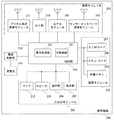
図1は、本実施形態に係る通信ネットワークシステム100の概略構成を示す機能ブロック図である。通信ネットワークシステム100は、大きい商業施設に設けられた施設構内システム800と、携帯電話200及び業務用携帯型無線機400(図4参照)と接続するPND500とで構成されている。施設構内システム800は、施設構内のユーザが所持する携帯電話200や業務用携帯型無線機400と通信可能となっており、外部のデジタル放送網720の放送波を中継したり、GPS衛星700からの位置情報を提供したり、施設構内の所定の情報を提供する。
FIG. 1 is a functional block diagram showing a schematic configuration of a communication network system 100 according to the present embodiment. The communication network system 100 includes a
まず、図2をもとに、通信ネットワークシステム100を用いた情報配信処理の概要について説明する。商業施設やオフィス、駅、空港などの公共施設の構内において、携帯電話200でGPS衛星700による位置情報を取得するのは、困難である。このため、近年、IMES(INDOOR MESSAGING SYSTEM)と称される技術が提案され導入が進みつつある。IMESでは、詳細後述するIMES端末803からGPSと互換性のある信号を送出することで、その信号を既存のGPS機能を有する携帯電話200等で受信して利用することができる。一般に、IMESを利用して計測できる位置の精度は数mと言われている。
First, an outline of information distribution processing using the communication network system 100 will be described with reference to FIG. It is difficult to acquire position information by the
そして、ZigBee(登録商標)などに代表されるセンサ・ネットワーク固定端末(動態監視用センサ・ネットワーク固定端末806等)を介し、利用客が携行している携帯電話200や、従業員が携行する携帯電話200又は業務用携帯型無線機400と以下の様な情報の授受を行う。
A
(1)位置情報と状態の取得
出入口に設置されたZigBee固定端末(動態監視用センサ・ネットワーク固定端末806)は、利用客や従業員が施設内の入退場する都度、動態情報を後述の動態監視サーバ856に通知する。
エレベータ、エスカレータ、階段付近に設置された動態監視用センサ・ネットワーク固定端末806は、利用客や従業員がいるフロアーが変わる都度、そのフロアーの階数を示す空間コードを、当該者が携行する携帯電話200等に通知する。
携帯電話200等は、空間コードが更新される都度、動態情報を動態監視用センサ・ネットワーク固定端末806を介して、動態情報を動態監視サーバ856に通知する。
(1) Acquisition of location information and status The ZigBee fixed terminal (dynamic monitoring sensor / network fixed terminal 806) installed at the entrance / exit changes the dynamic information described later when a user or employee enters or exits the facility. The
The sensor / network
The
(2)施設に関わる情報の提供
火災や地震・洪水等の災害が発生した場合、施設構内システム800は、動態監視用センサ・ネットワーク固定端末806とギャップフィラ装置807を併用して、利用客や従業員が携行する携帯電話200等に避難を誘導する為の情報を配信する。平常時の場合、商業施設や駅、空港などにおいて、施設構内システム800は、動態監視用センサ・ネットワーク固定端末806とギャップフィラ装置807を併用して、利用客に対して、当該施設の店舖広告や交通機関の運行状況などの情報を提供する。
(2) Provision of information related to facilities When a disaster such as a fire, earthquake, or flood occurs, the
図1の説明に戻り、上記情報の授受を実現するシステム構成について説明する。
施設構内システム800は、防災管理室850と回線・端末網880とから構成されており、情報配信システムとしての機能を有している。防災管理室850は、デジタル通信回線網870を介して構内の防災及び監視処理を行うために、防災管理室固定端末851と、位置情報管理システム863と、動態管理システム864と、設備監視システム865と、防災情報システム866とを備えている。
Returning to the description of FIG. 1, a system configuration for realizing the exchange of the information will be described.
The
位置情報管理システム863は、構内位置情報管理サーバ854と、構内位置情報データベース855とを有している。構内位置情報管理サーバ854は、管理者の操作に基づいて、構内の区画毎の構内図を構内位置情報データベース855に登録する。さらに、構内位置情報管理サーバ854は、区画毎の空間コードのリストを構内位置情報データベース855に登録する。なお、空間コードとは、各施設の特定の場所や区画に任意で割り当てることができるコードであり、構内で放送される情報の暗号を解除する際の解除キーとしても使用される。
The location
動態管理システム864は、動態監視サーバ856と、動態履歴データベース857とを有している。動態監視サーバ856は、構内のユーザの動態情報を監視する。具体的には、動態監視サーバ856は、携帯電話200または業務用携帯型無線機400から送信された動態情報を取得し、受信した動態情報に受信時刻を付与して、動態履歴データベース857に記録する。動態情報とは、UIMカードの製造番号、GPS位置情報、空間コードの取得の有無等である。
The
設備監視システム865は、構内設備監視サーバ858と設備監視履歴データベース859とを備えている。構内設備監視サーバ858は、構内全域から取得した設備状態情報に、受信時間を付与し、設備監視履歴データベース859に記録する。言い換えると、構内設備監視サーバ858は、異常検知フラグが有効になっている空間コードを取得した場合、その旨を反映させた設備状態情報を設備監視履歴データベース859に記録する。さらに、構内設備監視サーバ858は、防災管理室固定端末851を介して、施設管理者に火災が発生したことをアラームで知らせる。
The
防災情報システム866は、防災情報配信サーバ860と防災情報データベース861とを有している。防災情報配信サーバ860は、施設構内に関わる情報を防災情報データベース861に登録し、逐次、デジタル放送を介して、各ユーザの携帯電話200に配信する。施設構内に関わる情報とは、例えば、構内の避難経路や店舗広告などが挙げられる。構内の避難経路については、どのような混雑状況に応じて、どの区画で、どのような災害(火災、水害、地震など)が発生した場合、どのような避難経路が適切なのか、予めシミュレーションした結果である。
The disaster
回線・端末網880は、デジタル通信回線網870と、外部連携端末装置821と、センサ系装置822と、動態監視用センサ・ネットワーク固定端末806と、放送系装置823とを備えている。外部連携端末装置821と、センサ系装置822と、動態監視用センサ・ネットワーク固定端末806と、放送系装置823は、デジタル通信回線網870を介して防災管理室850に接続されている。
The line /
外部連携端末装置821は、携帯電話向け基地局801と、フェムトセル(ミニ基地局)802と、IMES端末803とを備えている。携帯電話向け基地局801及びフェムトセル802は、携帯電話通信網に接続されている。また、IMES端末803は、施設構外に設置されたGPSアンテナに接続され、GPS衛星700から時刻データや衛星情報などが含まれた信号を取得するとともに、GPS衛星700の信号と同じメッセージ構造を使用し、GPS衛星700のデータの代わりにIMES端末803の設置場所の位置データを構内に送出する。
The external
センサ系装置822は、設備監視用センサ・ネットワーク固定端末804、センサ・探知機805、監視力メラ810、人感センサ811を備えている。設備監視用センサ・ネットワーク固定端末804は、センサ・探知機805から設備状態情報を取得し、空間コードを付与して所定の時間間隔で、デジタル通信回線網870を介し、構内設備監視サーバ858に通知する。監視力メラ810及び人感センサ811は、例えば、施設構内の所定場所、例えば、出入り口付近に設置され、人の往来を検知する。
The
動態監視用センサ・ネットワーク固定端末806は、上述したように、ZigBee(登録商標)などに代表されるセンサ・ネットワーク固定端末であり、出入口付近に存在する携帯電話200に対して、動態情報通知要求を送信し、また、携帯電話200から前記の要求に応じて送信されてきた動態情報を取得する。
As described above, the movement monitoring sensor / network fixed
放送系装置823は、メディアコンバータ809と、混合装置808と、ギャップフィラ装置807とを備えている。
The
メディアコンバータ809は、構内位置情報管理サーバ854から取得した情報をデジタル放送波のデータに変換し、混合装置808へ伝送する。したがって、混合装置808へ伝送された情報は、構内位置情報を含む。混合装置808は、所定の受信装置にデジタル放送網720から受信したデジタル地上放送波と、構内の位置情報を含むデジタル放送波とを混合し、ギャップフィラ装置807へ伝送する。ギャップフィラ装置807は、混合装置808から伝送されてきたデジタル放送波を施設構内に送出する。
The
つぎに、図3もとに、携帯電話200の構成について説明する。
携帯電話200は、一般的な通信機能とともに、GPS機能及びセンサ・ネットワーク機能を有している。具体的には、携帯電話200は、制御部250と、通信モジュール260と、記憶モジュール270と、入出力モジュール280と、電源制御部214及び充電池215を備える。制御部250は、主制御部201と、信号処理部202を備える。通信モジュール260は、センサ・ネットワーク通信モジュール208と、GPSモジュール209と、RF部210と、デジタル放送受信モジュール211とを備える。
Next, the configuration of the
The
主制御部201は、携帯電話200を統括的に制御する。また、信号処理部202は、通信のための符号化/復号処理やアプリケーションの実行のために、各種の信号処理を実行する。記憶モジュール270は、内蔵メモリ205と、メモリ・カード206と、UIM(User Identify Module)カード207とを備える。UIMカード207は、携帯電話会社が発行する、契約者情報を記録したICカードである。入出力モジュール280は、表示部203と、操作部204と、マイク212と、スピーカ213とを備える。
The
つぎに、図4をもとに、業務用携帯型無線機400及びそれに接続するPND500の構成について説明する。業務用携帯型無線機400は、一般的なデジタル無線機であって、制御部450と、入出力モジュール480と、RF部405と、内蔵メモリ406と、インタフェイス411と、電源制御部409及び充電池410とを備える。入出力モジュール480は、表示部403と、操作部404と、マイク407と、スピーカ408とを備えている。制御部450は、業務用携帯型無線機400を統括的に制御するための主制御部401と、通信のための各種処理やアプリケーションの実行のために、各種の信号処理を実行する信号処理部402とを備えている。
Next, with reference to FIG. 4, the configuration of the
PND500は、小型のナビゲーション装置であって、制御部550と、表示部503と、操作部504と、内蔵メモリ505と、地図記憶装置506と、GPSモジュール507と、センサ・ネットワーク通信モジュール508と、電源制御部509と充電池510とを備える。なお、制御部550は業務用携帯型無線機400とインタフェイス411により通信可能に接続される。制御部550は、PND500を統括的に制御する主制御部501と、ナビゲーションのための処理や業務用携帯型無線機400との通信のための各種信号処理を行う信号処理部502とを備えている。
The
以上の構成をもとに、通信ネットワークシステム100の動作例を説明する。ここでは、ユーザが利用する端末として携帯電話200について例示するが、業務用携帯型無線機400であってもよい。
<平常時>
[フェーズ1]
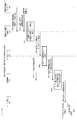
ユーザが施設へ入場するときの動作を図5のチャート図に基づき説明する。
(1)携帯電話200を携帯したユーザが、施設構内に入場する。
(2)監視力メラ810や人感センサ811などが、出入ロにおける人の往来を検知する(S101)。その検知結果をトリガとして、動態監視用センサ・ネットワーク固定端末806は、出入口付近に存在する携帯電話200に対して、動態情報通知要求を送信する(S102)。
(3)携帯電話200は、センサ・ネットワーク通信モジュール208を介して、動態情報(UIMカードの製造番号、GPS位置情報、空間コードの取得の有無)を、動態監視用センサ・ネットワーク固定端末806に通知する(S103)。
Based on the above configuration, an operation example of the communication network system 100 will be described. Here, although the
<Normal time>
[Phase 1]
The operation when the user enters the facility will be described with reference to the chart of FIG.
(1) A user carrying the
(2) The
(3) The
(4)動態監視用センサ・ネットワーク固定端末806は、携帯電話200から取得した動態情報に、この動態監視用センサ・ネットワーク固定端末806に割り当てられている空間コードを上書きし、デジタル通信回線網870を介して、動態監視サーバ856に送信する(S104)。
(5)動態監視サーバ856は、受信した当該動態情報に、受信時刻を付与した後(S105)、動態履歴データベース857に記録する(S106)。
(6)動態監視用センサ・ネットワーク固定端末806は、予め構内位置情報管理サーバ854に割り当てられている、出入口周辺の空間コードを携帯電話200へ通知する(S107)。
(4) The movement monitoring sensor / network fixed terminal 806 overwrites the movement information acquired from the
(5) The
(6) The movement monitoring sensor / network fixed
(7)携帯電話200は、空間コードを取得すると、デジタル放送受信モジュール211を介して、構内に関する位置情報等を受信できる状態に切り替える(S108)。
(8)携帯電話200は、施設構内のデジタル放送(後述のS160による放送)を受信し、現時点で取得している空間コードを解除キーとして、施設構内に関わる情報について、暗号を解除し(S109)、当該情報を内蔵メモリ205またはメモリ・カード206に一時的に格納する(S110)。
(9)ユーザは、操作部204に所定の操作を行い(S111)、表示部203を介して、施設構内に関わる情報を知ることができる(S112)。
(7) When the
(8) The
(9) The user performs a predetermined operation on the operation unit 204 (S111), and can know information related to the facility premises via the display unit 203 (S112).
(10)施設構内に関わる情報の登録・配信処理(S150、S160)について図6及び図7をもとに説明する。
図6の構内区画情報の登録処理(S150)として、構内位置情報管理サーバ854において、管理者は、構内の区画毎の構内図を作成し(S151)、作成した区画毎の構内図を構内位置情報データベース855に登録する(S152)。さらに、管理者は、区画毎の空間コードのリストを作成し(S153)、構内位置情報データベース855に登録する(S154)。
(10) Information registration / distribution processing (S150, S160) related to the facility premises will be described with reference to FIGS.
In the site location
構内の避難経路については、どのような混雑状況に応じて、どの区画で、どのような災害(火災、水害、地震など)が発生するか、どのような避難経路が適切なのか、予めシミュレーションした結果を、防災情報配信サーバ860を介して、防災情報データベースに登録しておき、逐次、デジタル放送を介して、図7のフローによって、各ユーザの携帯電話200に配信する(S160)。
Regarding the evacuation route on the premises, it was simulated in advance what kind of disaster (fire, flood, earthquake, etc.) occurred in which section according to what kind of congestion situation, and what kind of evacuation route was appropriate. The result is registered in the disaster prevention information database via the disaster prevention
具体的には、図7に示すように、構内位置情報管理サーバ854は、構内位置情報データベース855から区画毎の構内図と空間コードを読み出し(S161)、さらに施設構内の各種サーバから施設に関わる各種情報を取得する(S162)。そして、構内位置情報管理サーバ854は、空間コードをキーとして、区画毎に配信したい情報を暗号化し(S163)、暗号化した情報をメディアコンバータ809へ転送する(S164)。メディアコンバータ809は、構内位置情報管理サーバ854から取得したIP形式の情報をデジタル放送波のデータに変換し(S165)、混合装置808へ構内位置情報を含むデジタル放送波を伝送する(S166)。つまり、混合装置808へ伝送された情報には、構内位置情報が含まれる。
Specifically, as shown in FIG. 7, the premises location
続いて、混合装置808は、所定の受信装置により受信したデジタル地上放送波(S167)と、上記構内の位置情報を含むデジタル放送波とを混合し(S168)、混合したデジタル放送波をギャップフィラ装置807へ伝送する(S169)。ギャップフィラ装置807は、伝送されてきたデジタル放送波を施設構内(携帯電話200等)に送出する(S170)。
Subsequently, the
[フェーズ2]
つぎに、ユーザが施設内を移動するときの動作について図8を参照して説明する。
(1)携帯電話200は、IMES端末803から送信されるGPS位置情報を取得し(S201)、内蔵メモリ205またはメモリ・カード206に格納された動態情報を更新する(S202)。
(2)動態監視用センサ・ネットワーク固定端末806は、周辺の携帯電話200に対してポーリングするとともに、当該動態監視用センサ・ネットワーク固定端末806に予め割り当てられている空間コードを通知する(S203)。
(3)携帯電話200は、空間コードを取得し、内蔵メモリ205またはメモリ・カード206に格納された動態情報と比較し(S204)、空間コードが異なっている場合(S204のY)、ユーザが移動したと判断し、内蔵メモリ205またはメモリ・カード206に格納された動態情報を更新する(S205)。空間コードが同一であれば(S204のN)、S201の処理に戻る。
(4)以降は、フェーズ1のS103〜S112までのフローと同じフローで動作する。つまり、携帯電話200は、動態情報を動態監視用センサ・ネットワーク固定端末806に通知する(S206)。つぎに、動態監視用センサ・ネットワーク固定端末806は、更新後の空間コードが付加された動態情報を動態監視サーバ856に送信する(S207)。続いて、動態監視サーバ856は、受信した当該動態情報に、受信時刻を付与し(S208)、動態履歴データベース857に記録する(S209)。
[Phase 2]
Next, an operation when the user moves in the facility will be described with reference to FIG.
(1) The
(2) The dynamic monitoring sensor / network fixed terminal 806 polls the surrounding
(3) The
(4) After that, the same flow as the flow from S103 to S112 of the
(5)携帯電話200は、デジタル放送受信モジュール211を介した位置情報の受信に切り替える(S210)。
(6)さらに、携帯電話200は、施設構内のデジタル放送(S160による放送)を受信し(S210)、現時点で取得している空間コードを解除キーとして、施設構内に関わる情報について、暗号を解除し(S211)、当該情報を内蔵メモリ205等に格納する(S212)。
(7)そして、ユーザは、操作部204に所定の操作を行い(S213)、表示部203を介して、施設構内に関わる情報を知ることができる(S214)。
(5) The
(6) In addition, the
(7) Then, the user performs a predetermined operation on the operation unit 204 (S213), and can know information related to the facility premises via the display unit 203 (S214).
所定の時間間隔で動態情報を通知したり、GPS位置情報が変化する度に動態情報を通知したりすると、ラッシュ時の駅や空港などのように、利用客が混み合っている場合、動態監視サーバ856のトラフィックが膨大になってシステムダウンを引き起こす要因になると考えられる。そこで、上述のフローで示すように、空間コードの変化をトリガとして携帯電話200から動態監視サーバ856へ動態情報を通知する。
When dynamic information is notified at a predetermined time interval or when dynamic position information is notified every time GPS position information changes, dynamic monitoring is performed when users are crowded, such as at a rush hour station or airport. It is considered that the traffic of the
[フェーズ3]
施設から退場するときの動作について図9に示すフローに基づいて説明する。
(1)携帯電話200を携帯したユーザが退場する為に、施設構内の出入口を通過する。
(2)すると、動態監視用センサ・ネットワーク固定端末806は、監視力メラ810や人感センサ811などにより、出入ロにおける人の往来を検知する(S301)。それをトリガとして、動態監視用センサ・ネットワーク固定端末806は、出入口付近に存在する携帯電話200に対して、動態情報通知要求と退場したこと示すコードを送信する(S302)。
(3)携帯電話200は、センサ・ネットワーク通信モジュール208を介して、動態情報を、動態監視用センサ・ネットワーク固定端末806に通知する(S303)。
(4)動態監視用センサ・ネットワーク固定端末806は、携帯電話200から取得した動態情報に、当該動態監視用センサ・ネットワーク固定端末806に割り当てられている空間コードに退場を示すコードを上書きして(S304)、デジタル通信回線網870を介して動態監視サーバ856に送信する(S305)。
(5)動態監視サーバ856は、受信した当該動態情報に、受信時刻を付与した後(S306)、動態履歴データベース857に記録する(S307)。
(6)このとき、携帯電話200は、退場を示すコ一ドを受信すると、内蔵メモリ205またはメモリ・カード206に格納された動態情報のうち、空間コードにヌル値を上書きする(S308)。
(7)携帯電話200は、内蔵メモリ205またはメモリ・カード206に一時格納された施設構内に関わる情報をメモリから削除する(S309)。
[Phase 3]
The operation when leaving the facility will be described based on the flow shown in FIG.
(1) In order for the user carrying the
(2) Then, the movement monitoring sensor / network fixed
(3) The
(4) The movement monitoring sensor / network fixed terminal 806 overwrites the movement information acquired from the
(5) The
(6) At this time, when receiving the code indicating exit, the
(7) The
[フェーズ4]
災害発生時に対応した動作(平常時の動作と災害発生時の動作)について、図10及び図11に示すフローに基づいて説明する。
(1)図10に示すように平常時において、各種のセンサ・探知機805は、設備の状態(設備状態情報)を検知し(S401)、その設備状態情報を設備監視用センサ・ネットワーク固定端末804へ通知する(S402)。設備監視用センサ・ネットワーク固定端末804は、各種センサ・探知機805から取得した設備状態情報に空間コードを付与したのち(S403)、所定の時間間隔で、デジタル通信回線網870を介し、構内設備監視サーバ858に通知する(S404)。
(2)構内設備監視サーバ858は、構内全域から取得した設備状態情報に、受信時間を付与し(S405)、設備監視履歴データベース859に記録する(S406)。
[Phase 4]
The operation corresponding to the occurrence of a disaster (normal operation and operation when a disaster occurs) will be described based on the flow shown in FIGS.
(1) As shown in FIG. 10, in normal times, various sensors /
(2) The premises
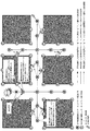
(3)ここで、図12で示すように、ある区画で火災が発生した状況を想定する。煙探知機や熱探知機、CO濃度センサ等の各種センサ・探知機805は、火災が発生したことを検知し(S410)、検知内容を設備監視用センサ・ネットワーク固定端末804に通知する(S411)。
(3) Here, as shown in FIG. 12, it is assumed that a fire has occurred in a certain section. Various sensors /
(4)すると、設備監視用センサ・ネットワーク固定端末804は、火災の種別によって異常検知フラグを生成し、火災が発生した区域の空間コードに異常検知フラグを付与し(S412)、異常検知フラグが付与された空間コードをデジタル通信回線網870を介し、構内設備監視サーバ858に通知する(S413)。同様に、隣接する動態監視用センサ・ネットワーク固定端末806に対しても、異常検知フラグを付与したコードを通知する(S414)。異常検知フラグとして、例えば、平時には「0」が、火災発生時には「1」が、水害発生時には「2」が設定される。
(5)構内設備監視サーバ858は、異常検知フラグが有効になっている空間コードを取得した場合、その旨を反映させた設備状態情報を設備監視履歴データベース859に記録する(S415)。さらに、構内設備監視サーバ858は、防災管理室固定端末851に通知し(S416)、その通知を受けた防災管理室固定端末851は施設管理者に火災が発生したことをアラームで知らせる(S417)。
(6)異常検知フラグが付与された区間コードを受信した動態監視用センサ・ネットワーク固定端末806は、つぎに隣接する動態監視用センサ・ネットワーク固定端末806’に通知し(S418)、火災発生元の区域を起点として、ドミノ倒し方式で、立て続けに、隣接する動態監視用センサ・ネットワーク固定端末806’に対して、異常検知フラグが付与された区間コードが通知される。
(4) Then, the equipment monitoring sensor / network fixed
(5) When the on-premises
(6) The movement monitoring sensor / network fixed terminal 806 that has received the section code to which the abnormality detection flag has been added notifies the adjacent movement monitoring sensor / network fixed terminal 806 ′ (S418), and the fire occurrence source The section code to which the abnormality detection flag is added is notified to the adjacent dynamic monitoring sensor / network fixed terminal 806 ′ in succession by the domino-inclined method starting from the above-mentioned area.
(7)続いて、動態監視用センサ・ネットワーク固定端末806は、周辺に存在する携帯電話200に対して、動態情報通知要求と共に、異常検知フラグが付与された空間コ一ドを通知する(S419)。
(8)携帯電話200は、動態監視用センサ・ネットワーク固定端末806を介して、動態監視サーバ856に、動態情報を通知する(S420)。動態監視サーバ856は、通知された動態情報に受信時刻を付与し(S421)、構内全域の動態情報を動態履歴データベース857に記録する(S422)。
(7) Subsequently, the dynamic monitoring sensor / network fixed
(8) The
(9)携帯電話200は、異常検知フラグをキーとして、内蔵メモリ205やメモリ・カード206に予め記憶しておいた避難経路情報を呼び出し(S425)、表示部203を介してユーザに表示する(S426)。
(10)また、施設管理者は、防災管理室固定端末851を介して、施設全域から収集した動態情報や設備の状態情報などを各種サーバ854、856、858、860から呼び出し(S423)、表示部852に表示する。施設管理者は、当該情報をもとに、現場の従業員や救助隊に対して、指示を出すことができる(S424)。例えば、災害が発生している区域に、動態情報の変化がないような場合は、何らかの理由で利用者が移動できない可能性があるので、その区域に向かうよう、従業員や救助隊に指示を与えることができる。
(9) The
(10) In addition, the facility manager calls the dynamic information collected from the entire facility and the state information of the equipment from the
以上、本実施形態を作用・効果を簡単にまとめると以下の通りである。
(1)各種外部I/Fモジュール(デジタル放送、GPS、センサ・ネットワーク)を内蔵した携帯電話及び業務用無線端末を使って、区域ごとに割り当てられている空間コードについて、センサ・ネットワークを介して取得する。そして、携帯電話は、区域ごとに暗号化されたデジタル放送から配信される避難経路情報をはじめとした施設構内に関する情報を、空間コードを解除キーとして復号化し、表示部に表示する。これによって、構内が混雑している場合でも、利用者や従業員は、避難経路情報等の施設構内の情報を個別に確認できる。
As described above, the operation and effect of this embodiment can be summarized as follows.
(1) Using a mobile phone with a built-in external I / F module (digital broadcasting, GPS, sensor network) and a commercial wireless terminal, the spatial code assigned to each area via the sensor network get. Then, the cellular phone decrypts information related to the facility premises including the evacuation route information distributed from the digital broadcast encrypted for each area using the space code as a release key and displays the information on the display unit. As a result, even when the premises are congested, users and employees can individually check information on the premises such as evacuation route information.
(2)異常検知フラグの値を災害の種別ごとに割り当て、各種センサや探知機で検知した項目によって、異常検知フラグの値を指定し、空間コ一ドに付与する。これによって、施設構内にいる利用者や従業員、あるいは、防災管理室にいる施設管理者に対して、どの区域でどの様な災害が生じたかを、センサ・ネットワークを介して、迅速に知らせることができる。 (2) The value of the abnormality detection flag is assigned to each disaster type, and the value of the abnormality detection flag is designated according to the items detected by various sensors and detectors and assigned to the space code. In this way, users and employees within the facility premises, or facility managers in the disaster prevention management room, can be notified quickly via the sensor network of what kind of disaster occurred in which area. Can do.
(3)各種外部I/Fモジュール(デジタル放送、GPS、センサ・ネットワーク)を内蔵した携帯電話及び業務用無線端末を使って、デジタル放送から配信される災害の種別ごとに想定される避難経路情報を予め取得する。そして、センサ・ネットワークを介して取得した異常検知フラグを解除キーとして復号化し、自動的に携帯電話の表示部に表示させる。これによって、施設構内にいる利用者や従業員に対して個別に、発生した災害の内容に応じた避難経路情報を、迅速に知らせることができる。 (3) Evacuation route information assumed for each type of disaster delivered from digital broadcasting using mobile phones and commercial wireless terminals with built-in various external I / F modules (digital broadcasting, GPS, sensor network) Is acquired in advance. Then, the abnormality detection flag acquired via the sensor network is decrypted as a release key and automatically displayed on the display unit of the mobile phone. As a result, it is possible to promptly notify evacuation route information corresponding to the contents of the disaster that has occurred individually to users and employees in the facility premises.
(4)センサ・ネットワーク固定端末と、センサ・ネットワーク通信モジュールを内蔵した携帯電話間で通信を可能にする。これによって、災害が発生した区域を起点として、複数の経路で情報を伝達することができる。その結果、周辺の携帯電話を所有する周辺の利用客や従業員に対して、遅延なく、かつ可用性を高めて、避難経路情報などを通知することができる。 (4) Communication is possible between a sensor / network fixed terminal and a mobile phone incorporating a sensor / network communication module. As a result, information can be transmitted through a plurality of routes starting from the area where the disaster occurred. As a result, it is possible to notify the evacuation route information and the like to the nearby customers and employees who own the surrounding mobile phones without delay and with high availability.
(5)IMES端末を併用することにより、施設構内にいる場合でも、GPS機能を有する携帯電話や業務用携帯型無線機を用いて、災害発生時において、救助活動に携わる組織は、利用者や従業員が施設構内のどのあたりに取り残されているかを概略的に把握することができる。 (5) By using the IMES terminal in combination, even if you are in the facility premises, using a mobile phone with GPS function or a portable radio for business use, the organization involved in the rescue operation in the event of a disaster It is possible to roughly grasp where the employee is left in the facility.
以上、本発明を実施形態をもとに説明した。この実施形態は例示であり、それらの各構成要素の組み合わせにいろいろな変形例が可能なこと、またそうした変形例も本発明の範囲にあることは当業者に理解されるところである。 The present invention has been described based on the embodiments. This embodiment is an exemplification, and it will be understood by those skilled in the art that various modifications can be made to combinations of these components, and such modifications are also within the scope of the present invention.
本実施形態を簡単にまとめると以下の通りである。
本実施の形態に係る情報配信システムは、センサ・ネットワーク・モジュールを用いて、複数の携帯端末から位置情報を取得する位置情報収集手段と、前記位置情報に対応したコードを前記携帯端末へ通知するコード通知手段と、前記コードを解除キーとして暗号化された情報を前記携帯端末が利用可能なデータ形式で出力する情報提供手段と、周囲に発生した異常発生を検知する検知手段と、を備え、前記情報提供手段は、前記異常発生に関する情報を前記暗号化された情報に含める。
また、別の観点では、所定の施設内に設置される情報配信システムにおける情報配信方法であって、携帯端末が有する位置情報を取得する位置情報取得工程と、取得した位置情報に対応した空間コードを前記携帯端末へ送信するコード通知工程と、前記施設内における異常発生を検知する異常検知工程と、前記異常発生が検知された位置を特定し、前記特定された位置に関する情報を含めたうえで、前記空間コートを解除キーとして暗号化された前記施設に関する情報を出力する情報提供工程と、を備える。
前記位置情報取得工程は、センサ・ネットワーク・モジュールを介して前記位置情報を取得する。
また、携帯端末の存在又は前記携帯端末のユーザを検知したときに、前記携帯端末に対して、前記位置情報を要求する位置情報要求工程を備える。
また、前記携帯端末に関する情報を動態情報として取得する動態情報取得工程を備える。
また、施設内に異常が発生したときに、前記動態情報に基づいて、前記携帯端末のユーザの移動状況を確認する動態状況確認工程を備える。
前記位置情報は、IMESによる情報である。
This embodiment is briefly summarized as follows.
The information distribution system according to the present embodiment uses a sensor network module to notify the mobile terminal of location information collection means for acquiring location information from a plurality of mobile terminals, and a code corresponding to the location information. Code notification means, information providing means for outputting information encrypted with the code as a release key in a data format that can be used by the mobile terminal, and detection means for detecting the occurrence of an abnormality occurring around, The information providing means includes information relating to the occurrence of the abnormality in the encrypted information.
In another aspect, an information distribution method in an information distribution system installed in a predetermined facility, a position information acquisition step of acquiring position information possessed by a mobile terminal, and a space code corresponding to the acquired position information A code notification step for transmitting the information to the portable terminal, an abnormality detection step for detecting the occurrence of an abnormality in the facility, a position where the occurrence of the abnormality is detected, and including information on the specified position And an information providing step of outputting information on the facility encrypted using the space court as a release key.
In the position information acquisition step, the position information is acquired via a sensor network module.
Moreover, when the presence of a portable terminal or the user of the said portable terminal is detected, the position information request | requirement process which requests | requires the said positional information with respect to the said portable terminal is provided.
In addition, a dynamic information acquisition step of acquiring information related to the mobile terminal as dynamic information is provided.
In addition, when an abnormality occurs in the facility, there is provided a behavior status confirmation step of confirming the movement status of the user of the mobile terminal based on the behavior information.
The position information is information by IMES.
100 通信ネットワークシステム
200 携帯電話
207 UIMカード
208 センサ・ネットワーク通信モジュール
209 GPSモジュール
211 デジタル放送受信モジュール
400 業務用携帯型無線機
500 PND
507 GPSモジュール
508 センサ・ネットワーク通信モジュール
700 GPS衛星
720 デジタル放送網
800 施設構内システム
803 IMES端末
804 設備監視用センサ・ネットワーク固定端末
805 センサ・探知機
806 動態監視用センサ・ネットワーク固定端末
807 ギャップフィラ装置
808 混合装置
809 メディアコンバータ
810 監視力メラ
811 人感センサ
850 防災管理室
851 防災管理室固定端末
854 構内位置情報管理サーバ
855 構内位置情報データベース
856 動態監視サーバ
857 動態履歴データベース
858 構内設備監視サーバ
859 設備監視履歴データベース
860 防災情報配信サーバ
861 防災情報データベース
870 デジタル通信回線網
DESCRIPTION OF SYMBOLS 100
507
Claims (1)
前記位置情報に対応したコードを前記携帯端末へ通知するコード通知手段と、
前記コードを解除キーとして暗号化された情報を前記携帯端末が利用可能なデータ形式で出力する情報提供手段と、
周囲に発生した異常発生を検知する検知手段と、
を備え、
前記情報提供手段は、前記異常発生に関する情報を前記暗号化された情報に含めることを特徴とする情報配信システム。 Location information collecting means for acquiring location information from a plurality of mobile terminals using a sensor network module;
Code notification means for notifying the mobile terminal of a code corresponding to the position information;
Information providing means for outputting the information encrypted with the code as a release key in a data format usable by the mobile terminal;
Detection means for detecting the occurrence of abnormalities in the surroundings;
With
The information distribution system, wherein the information providing unit includes information on the occurrence of the abnormality in the encrypted information.
Priority Applications (1)
| Application Number | Priority Date | Filing Date | Title |
|---|---|---|---|
| JP2009229642A JP2011078001A (en) | 2009-10-01 | 2009-10-01 | Information distribution system |
Applications Claiming Priority (1)
| Application Number | Priority Date | Filing Date | Title |
|---|---|---|---|
| JP2009229642A JP2011078001A (en) | 2009-10-01 | 2009-10-01 | Information distribution system |
Publications (2)
| Publication Number | Publication Date |
|---|---|
| JP2011078001A true JP2011078001A (en) | 2011-04-14 |
| JP2011078001A5 JP2011078001A5 (en) | 2012-11-08 |
Family
ID=44021448
Family Applications (1)
| Application Number | Title | Priority Date | Filing Date |
|---|---|---|---|
| JP2009229642A Pending JP2011078001A (en) | 2009-10-01 | 2009-10-01 | Information distribution system |
Country Status (1)
| Country | Link |
|---|---|
| JP (1) | JP2011078001A (en) |
Cited By (6)
| Publication number | Priority date | Publication date | Assignee | Title |
|---|---|---|---|---|
| JP2013186554A (en) * | 2012-03-06 | 2013-09-19 | Nohmi Bosai Ltd | Rescue activity support system |
| JP2013213804A (en) * | 2012-03-09 | 2013-10-17 | Ricoh Co Ltd | Communication terminal, communication method and program |
| JP2014021867A (en) * | 2012-07-20 | 2014-02-03 | Ricoh Co Ltd | Information transmission device, information transmission method, and information transmission system |
| JP2014241551A (en) * | 2013-06-12 | 2014-12-25 | 日本電気株式会社 | Controller, communication system and information provision method |
| US9094793B2 (en) | 2012-09-21 | 2015-07-28 | Ricoh Company, Ltd. | Transmission system, location management system, and method of transmitting location data |
| US9426775B2 (en) | 2012-09-21 | 2016-08-23 | Ricoh Company, Ltd. | Communication terminal, communication method, and recording medium storing communication terminal control program |
Citations (5)
| Publication number | Priority date | Publication date | Assignee | Title |
|---|---|---|---|---|
| JP2002128406A (en) * | 2000-10-25 | 2002-05-09 | Mitsubishi Electric Corp | In-building guide system using mobile communication terminal |
| JP2002262351A (en) * | 2001-02-28 | 2002-09-13 | Ntt Docomo Inc | Configuration of communication service area in mobile communication system, information distribution method and its mobile communication system |
| JP2003151058A (en) * | 2001-11-16 | 2003-05-23 | Nec Eng Ltd | Escape guiding system |
| JP2004112210A (en) * | 2002-09-17 | 2004-04-08 | Ntt Docomo Inc | Information transmission system, information transmission apparatus, and information transmission method |
| JP2008158580A (en) * | 2006-12-20 | 2008-07-10 | Softbank Mobile Corp | Service providing system, service providing method, and service providing program |
-
2009
- 2009-10-01 JP JP2009229642A patent/JP2011078001A/en active Pending
Patent Citations (5)
| Publication number | Priority date | Publication date | Assignee | Title |
|---|---|---|---|---|
| JP2002128406A (en) * | 2000-10-25 | 2002-05-09 | Mitsubishi Electric Corp | In-building guide system using mobile communication terminal |
| JP2002262351A (en) * | 2001-02-28 | 2002-09-13 | Ntt Docomo Inc | Configuration of communication service area in mobile communication system, information distribution method and its mobile communication system |
| JP2003151058A (en) * | 2001-11-16 | 2003-05-23 | Nec Eng Ltd | Escape guiding system |
| JP2004112210A (en) * | 2002-09-17 | 2004-04-08 | Ntt Docomo Inc | Information transmission system, information transmission apparatus, and information transmission method |
| JP2008158580A (en) * | 2006-12-20 | 2008-07-10 | Softbank Mobile Corp | Service providing system, service providing method, and service providing program |
Cited By (6)
| Publication number | Priority date | Publication date | Assignee | Title |
|---|---|---|---|---|
| JP2013186554A (en) * | 2012-03-06 | 2013-09-19 | Nohmi Bosai Ltd | Rescue activity support system |
| JP2013213804A (en) * | 2012-03-09 | 2013-10-17 | Ricoh Co Ltd | Communication terminal, communication method and program |
| JP2014021867A (en) * | 2012-07-20 | 2014-02-03 | Ricoh Co Ltd | Information transmission device, information transmission method, and information transmission system |
| US9094793B2 (en) | 2012-09-21 | 2015-07-28 | Ricoh Company, Ltd. | Transmission system, location management system, and method of transmitting location data |
| US9426775B2 (en) | 2012-09-21 | 2016-08-23 | Ricoh Company, Ltd. | Communication terminal, communication method, and recording medium storing communication terminal control program |
| JP2014241551A (en) * | 2013-06-12 | 2014-12-25 | 日本電気株式会社 | Controller, communication system and information provision method |
Similar Documents
| Publication | Publication Date | Title |
|---|---|---|
| JP4349199B2 (en) | Space-time communication system | |
| US8760288B2 (en) | Remote evacuation reporting interface for first responder duty optimization in the field | |
| JP6105839B2 (en) | Fire alarm system | |
| US20160381537A1 (en) | Method of notification of fire evacuation plan in floating crowd premises | |
| JP2011078001A (en) | Information distribution system | |
| JP2009230203A (en) | Status information management system, method, and status information management server | |
| JP2000057457A (en) | Municipal disaster prevention system | |
| JP6900301B2 (en) | Disaster prevention support system | |
| JP2008011038A (en) | System and method for information notification, information apparatus, and program | |
| CN110009859B (en) | Emergency notification system and method | |
| KR100927581B1 (en) | Remote disaster prevention management system | |
| JP2020187719A (en) | Information processing system, information processing method, and remote area emergency prompt report providing system | |
| JP6505168B2 (en) | Notification system | |
| JP2005333232A (en) | Information distribution system and method, and information distribution program | |
| JP2005126216A (en) | Disaster information network | |
| JP2023089165A (en) | Notification processing device, notification processing method, program, and recording medium | |
| KR100761234B1 (en) | Integration control system, server and method by using interworking among control services | |
| JP2016153927A (en) | Display device, control device, system, and evacuation information provision method | |
| JP2009152724A (en) | Emergency communication system using mobile phone | |
| JP6517035B2 (en) | Alarm system and program | |
| JP6603546B2 (en) | Disaster prevention support system | |
| JP2007165979A (en) | Safety information service system, route searching server and portable terminal device | |
| JP2014137714A (en) | Danger prediction information notification system | |
| JP2004312577A (en) | System of sending information on approach of communication terminal | |
| KR102518678B1 (en) | Digital twin evacuation platform that provides safe evacuation route information in case of fire or disaster through digital twin |
Legal Events
| Date | Code | Title | Description |
|---|---|---|---|
| A521 | Written amendment |
Effective date: 20120925 Free format text: JAPANESE INTERMEDIATE CODE: A523 |
|
| A621 | Written request for application examination |
Effective date: 20120925 Free format text: JAPANESE INTERMEDIATE CODE: A621 |
|
| A977 | Report on retrieval |
Effective date: 20130729 Free format text: JAPANESE INTERMEDIATE CODE: A971007 |
|
| A131 | Notification of reasons for refusal |
Free format text: JAPANESE INTERMEDIATE CODE: A131 Effective date: 20130820 |
|
| A521 | Written amendment |
Free format text: JAPANESE INTERMEDIATE CODE: A523 Effective date: 20131018 |
|
| A131 | Notification of reasons for refusal |
Free format text: JAPANESE INTERMEDIATE CODE: A131 Effective date: 20140415 |
|
| A02 | Decision of refusal |
Free format text: JAPANESE INTERMEDIATE CODE: A02 Effective date: 20140819 |