JP2011069625A - Atmospheric corrosion testing device - Google Patents
Atmospheric corrosion testing device Download PDFInfo
- Publication number
- JP2011069625A JP2011069625A JP2009218403A JP2009218403A JP2011069625A JP 2011069625 A JP2011069625 A JP 2011069625A JP 2009218403 A JP2009218403 A JP 2009218403A JP 2009218403 A JP2009218403 A JP 2009218403A JP 2011069625 A JP2011069625 A JP 2011069625A
- Authority
- JP
- Japan
- Prior art keywords
- salt water
- corrosion
- salt
- discharge mechanism
- tested
- Prior art date
- Legal status (The legal status is an assumption and is not a legal conclusion. Google has not performed a legal analysis and makes no representation as to the accuracy of the status listed.)
- Pending
Links
Images

Abstract
Description
本発明は、大気中で使用される金属材料の腐食形態を再現できる試験方法およびその装置に係り、特に腐食を促進させる化学物質を被試験体に均一に付着させる方法および装置に関する。 The present invention relates to a test method and apparatus capable of reproducing the corrosion form of a metal material used in the atmosphere, and more particularly to a method and apparatus for uniformly attaching a chemical substance that promotes corrosion to a test object.
大気腐食の促進試験法としては、JIS Z 2371で規定されている塩水噴霧試験方法やJIS K 5600−7−9で規定されているサイクル腐食試験方法が知られており、規格に準拠した試験装置が用いられている。従来の試験装置では、腐食を促進させる化学物質として所定の濃度に調整された塩水を用い、この塩水を噴霧塔からミスト状に噴霧して被試験体に付着させる方法がとられた。この塩水の噴霧量に関しては、試験結果に影響するため、試験槽内の塩水の採取位置によるバラツキが少ないことが要求される。塩水噴霧のバラツキを小さくする方法として、例えば、噴霧塔を二重構造とすることにより改善する方法が特許として公開されている。 As an accelerated test method for atmospheric corrosion, a salt spray test method specified in JIS Z 2371 and a cyclic corrosion test method specified in JIS K 5600-7-9 are known, and test equipment conforming to the standard is used. Is used. In a conventional test apparatus, salt water adjusted to a predetermined concentration is used as a chemical substance that promotes corrosion, and this salt water is sprayed in a mist form from a spray tower to adhere to a test object. Since the spray amount of the salt water affects the test result, it is required that there is little variation depending on the salt water collection position in the test tank. As a method for reducing variations in salt spray, for example, a method for improving the spray tower by making the spray tower have a double structure is disclosed as a patent.
一方、霧状された噴霧された塩水が試験体に付着すると、噴霧された液滴が凝集して表面でぬれた状態になり、自然環境で飛来する海塩粒子のサイズが数10μm程度であるのと大きく異なる。その結果、実際の自然環境中に置かれている材料の腐食状態とはかけ離れているものであった。自然環境で飛来する塩粒子の付着状況を再現する方法としては、発生させた塩粒子を一定の緩衝空間を飛来させた後に被試験体に付着させることにより再現する方法が特許として公開されている。 On the other hand, when the sprayed salt water sprayed adheres to the specimen, the sprayed droplets aggregate and become wet on the surface, and the size of the sea salt particles flying in the natural environment is about several tens of μm. It is very different. As a result, it was far from the corrosive state of the material placed in the actual natural environment. As a method for reproducing the adhesion state of salt particles flying in the natural environment, a method for reproducing the generated salt particles by allowing them to adhere to a test object after flying in a certain buffer space has been published as a patent. .
上記塩水を噴霧することにより被試験体に塩分を付着させる方法では、自然環境で飛来する塩粒子を再現できないのと同時に、塩付着の繰り返しや被試験体の設置位置による付着塩分量のバラツキを十分に解消できていない課題がある。また、塩粒子を一定空間飛来させて付着させる方法では、自然環境で飛来する塩粒子を再現できても、被試験体の設置位置によるバラツキを制御できない課題がある。また、これらの方法による場合、付着塩分量のバラツキが大きいため、塩付着前後の重量を測ることによって付着塩分量を把握する必要がある。 In the method of attaching salt to the specimen by spraying the salt water, the salt particles flying in the natural environment cannot be reproduced, and at the same time, the amount of salt attached varies due to repeated salt adhesion and the location of the specimen. There are issues that have not been fully resolved. Further, in the method in which the salt particles are allowed to fly in a certain space and adhere, there is a problem that even if the salt particles flying in the natural environment can be reproduced, variation due to the installation position of the test object cannot be controlled. In addition, when these methods are used, there is a large variation in the amount of adhering salt. Therefore, it is necessary to grasp the amount of adhering salt by measuring the weight before and after the salt attachment.
本発明の目的は、自然環境で飛来する塩粒子を再現すると同時に、塩付着の繰り返しや試験槽内での被試験体の設置位置によるバラツキを小さくできる腐食試験装置を提供することにある。 An object of the present invention is to provide a corrosion test apparatus capable of reproducing salt particles flying in a natural environment, and at the same time reducing variations due to repeated salt adhesion and installation positions of test objects in a test tank.
(1)本発明は、恒温恒湿槽と、塩水吐出機構と、被腐食試験体を載せる架台と、洗浄機構とから構成され、吐出機構と対象物を相対移動させて塩水を付着させる腐食試験装置において、塩水吐出機構は周波数fにて吐出口より塩水を吐出し、塩水の吐出量qと、吐出機構と対象物との相対移動速度vの関係が (1) The present invention is composed of a constant temperature and humidity chamber, a salt water discharge mechanism, a gantry on which a specimen to be corroded is placed, and a cleaning mechanism, and a corrosion test in which salt water is adhered by moving the discharge mechanism and an object relative to each other. In the apparatus, the salt water discharge mechanism discharges salt water from the discharge port at the frequency f, and the relationship between the discharge amount q of the salt water and the relative moving speed v between the discharge mechanism and the object is given.
![]()
(2)本発明による腐食試験装置は、吐出量qが0.018mL/s以上であることを特徴としている。吐出量qが0.018mL/s以上であることによって、安定して塩水を吐出すことができる。
(3)本発明による腐食試験装置は、周波数fが1kHz以上であることを特徴としている。周波数fが1kHz以上であることによって、安定して塩水を吐出すことができる。
(4)本発明による腐食試験装置は、対象物に付着した塩水の直径が200μm以下であることを特徴としている。対象物に付着した塩水の直径が200μm以下であることによって、実環境と同様の腐食を再現することができる。
(5)本発明による腐食試験装置は、吐出口の直径を100μm以下としたことを特徴としている。吐出口の直径を100μm以下にすることによって、実環境と同様の腐食を再現することができる。
![]()
(2) The corrosion test apparatus according to the present invention is characterized in that the discharge amount q is 0.018 mL / s or more. When the discharge amount q is 0.018 mL / s or more, the salt water can be discharged stably.
(3) The corrosion test apparatus according to the present invention is characterized in that the frequency f is 1 kHz or more. When the frequency f is 1 kHz or more, salt water can be discharged stably.
(4) The corrosion test apparatus according to the present invention is characterized in that the diameter of the salt water adhering to the object is 200 μm or less. Corrosion similar to the actual environment can be reproduced when the diameter of the salt water adhering to the object is 200 μm or less.
(5) The corrosion test apparatus according to the present invention is characterized in that the diameter of the discharge port is 100 μm or less. By setting the diameter of the discharge port to 100 μm or less, corrosion similar to that in the actual environment can be reproduced.
本発明によれば、付着塩分量の精度を高めて塩分を付着させることができる。また、塩水を効率良く対象物に付着させることができるため、塩付着前後の重量を測るといった操作が不要となる。 According to the present invention, it is possible to increase the accuracy of the amount of adhering salt and adhere the salinity. Moreover, since salt water can be made to adhere to a target object efficiently, operation which measures the weight before and after salt attachment becomes unnecessary.
以下、本発明の詳細について実施例を用い説明する。 Hereinafter, the details of the present invention will be described using examples.
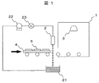
図1に、本実施例の大気腐食促進試験装置の構成図を示す。大気腐食促進試験装置は、主として、恒温恒湿槽1,塩水吐出機構2,洗浄機構3および移動架台4から構成され、被腐食試験体5を試験する。恒温恒湿槽1は、槽内の温度と湿度を独立して制御でき、かつ、プログラム制御により複数の温度と湿度の条件を連続に変化させる機能を有する。塩水吐出機構2は、超音波振動により塩水を滴状にして吐出すものである。洗浄機構3は、被試験体に洗浄水をかけ流し、試験体に付着した塩分を除去する。移動架台4は、被腐食試験体5を固定し、自身を塩水吐出機構2に対して移動させることにより、塩水吐出機構2から吐出された塩水を被腐食試験体5に点状に付着させる。なお、被腐食試験体に付着しない余分な塩水は、塩水回収器21に回収され、供給ポンプ22により塩水吐出機構に供給される。塩水を供給する経路には流量計23があり、塩水の供給量を調整する。
In FIG. 1, the block diagram of the atmospheric corrosion promotion test apparatus of a present Example is shown. The atmospheric corrosion acceleration test apparatus is mainly composed of a constant temperature and
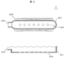
図2は本実施例における塩水吐出機構を示した図である。塩水吐出機構2は、塩水吐出機構本体201,塩水供給口202,超音波発振器203,吐出口204から構成される。吐出口を複数個、並列に設けることにより、一度に複数の液滴を被腐食試験体に付着させることができる。本実施例では塩水供給口202を101個設けた。塩水供給口202に塩水を供給すると共に、超音波発振器203を振動させ、吐出口24より塩水を滴状に吐出した。本実施例では、吐出口24の直径60μm,吐出口24の間隔500μmを使用したので、一度に幅50mmの領域に塩水を付着させることができる。塩水が安定して吐出されたのは、塩水の供給量が1.8mL/s以上の時であったので、本実施例では、塩水の供給量を0.018mL/sとした。また、塩水が滴状になって吐出されていたのは超音波発振器203の振動周波数が4000Hz以上の時であった。そこで、超音波発振器203の振動周波数を4000Hzとした。移動架台4を塩水吐出機構2に対して移動させることにより、滴状に吐出される塩水を被腐食試験体5に点状に付着させた。(1)式より、点状に付着させるために移動速度を2.0m/sとした。
FIG. 2 is a view showing a salt water discharge mechanism in the present embodiment. The salt
図3に塩水が被試験体5に付着した様子を示す。付着させた塩水6は円状となり、直径は200μmであった。また、付着させ塩水6の間隔は500μmであり、個々の液滴どうしを凝集させずに付着させることができた。本実施例では塩水として3.5%のNaCl水溶液を使用しており、被試験体に18.6mL/m2の塩水を付着させたので、0.65g/m2の塩分を付着させたことになる。また、塩水の濃度を変えることにより付着塩分量を調整することも可能である。
FIG. 3 shows a state in which salt water adheres to the
次に、この大気腐食促進試験装置における試験手順を示す。先ず、被腐食試験体5を洗浄および乾燥させた後に、移動架台4の全面に並べる。移動架台4に設置された被腐食試験体5が塩水吐出機構2の下を通過する際に、塩水吐出機構2から被腐食試験体5に向けて塩水が吐出されることにより、被腐食試験体5の表面に塩水が付着される。
Next, a test procedure in this atmospheric corrosion acceleration test apparatus will be shown. First, after the corroded
この試験材をプログラム制御された恒温恒湿槽1に挿入して腐食試験を開始する。塩水が付着した被腐食試験体5は、恒温恒湿槽1で所定の温湿度が組み合わせられた温湿度サイクルの環境で腐食試験される。今回、被腐食試験体5の挿入後の温湿度サイクルとして、先ず、60℃相対湿度35%RHの乾燥環境に3時間保持した後に40℃相対湿度95%RHの湿潤環境に3時間保持するサイクルを12回繰り返した。ここで、乾燥環境から湿潤環境および湿潤環境から乾燥環境への移行時間は、それぞれ1時間とし、一連のサイクルを8時間に設定した。
The test material is inserted into the temperature-controlled and
乾燥と湿潤の組み合わせ環境に被腐食試験体5を12サイクル計96時間暴露した後、移動架台4に設置された被腐食試験体5を水洗し、塩分を除去した。恒温恒湿槽1内には、洗浄機構3を設置しており、まず、洗浄機構3から洗浄水としての純水を被腐食試験体5にかけ流し被腐食試験体5に付着していた塩分を洗い流した。洗浄水の温度は30℃、温風の温度は50℃に設定した。この一連の塩水付着,温湿度サイクルと洗浄乾燥工程を繰り返すことにより腐食試験を継続した。温湿度サイクルでの乾燥・湿潤を4週間、または8週間繰り返し、その中で、週に二回、塩分付着と洗浄を行った。
After the corroded
これにより、実環境の腐食を再現することができた。 As a result, the corrosion of the actual environment could be reproduced.
実施例2として、実施例1とは吐出機構の形状および塩付着の条件が異なる場合の実施例について説明する。塩水吐出機構は、吐出口の直径が50μm、吐出口の間隔が400μmの形状のものを使用し、塩水吐出口1個あたりの吐出量を0.011mL/s、超音波発信器の振動周波数を5000Hz、被試験体の移動速度を2.0m/sにして塩水を付着させた。塩水として塩分濃度3.5%の人工海水を使用しており、付着塩分量は0.51g/m2であった。なお、大気腐食促進試験装置および大気腐食試験方法は実施例1と同様とした。 As Example 2, an example in which the shape of the discharge mechanism and the salt adhesion conditions are different from Example 1 will be described. The salt water discharge mechanism uses a discharge port with a diameter of 50 μm and a discharge port interval of 400 μm, a discharge amount per salt water discharge port of 0.011 mL / s, and a vibration frequency of the ultrasonic transmitter. The salt water was attached at 5000 Hz with the moving speed of the test object being 2.0 m / s. Artificial seawater having a salinity of 3.5% was used as the salt water, and the amount of adhering salt was 0.51 g / m 2 . The atmospheric corrosion acceleration test apparatus and the atmospheric corrosion test method were the same as in Example 1.
付着した塩水は円状になり、直径は150μmであった。また、付着した塩水の間隔は400μmであり、個々の液滴どうしを凝集させずに付着させることができた。 The attached salt water was circular and the diameter was 150 μm. Further, the interval between the adhering salt waters was 400 μm, and the individual droplets could be adhered without agglomeration.
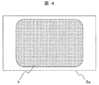
図4は腐食試験をした場合の腐食の様子を示す。被腐食試験体5の表面に腐食された部分7が均一に形成されており、実環境や実施例1の腐食形態と同様であった。
FIG. 4 shows the state of corrosion when a corrosion test is performed. The corroded
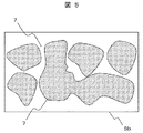
実施例3として、吐出口の寸法が不適正な場合の実施例について説明する。吐出口の直径が90μm、吐出口の間隔が1250μmの形状の塩水吐出機構を使用し、塩水吐出口1個あたりの吐出量を0.023mL/s、超音波発信器の振動周波数を1000Hz、被試験体の移動速度を1.25m/sにして塩を付着させた。塩水として塩分濃度3.5%の人工海水を使用しており、付着塩分量は0.51g/m2で、実施例2の場合と同等であった。なお、大気腐食促進試験装置および大気腐食試験方法は実施例1と同様とした。付着した塩水は円状になり、直径は390μmであった。また、付着した塩水の間隔は1250μmであり、個々の液滴どうしを凝集させずに付着させることができた。図5は腐食試験をした場合の腐食の様子を示す。塩水が付着した位置に腐食が集中してしまい、腐食された部分7と腐食されていない部分8が不均一であり、付着塩分量は0.51g/m2が同等であっても実施例2の腐食と異なっていた。
As Example 3, an example in which the dimensions of the discharge port are inappropriate will be described. A salt water discharge mechanism having a discharge port diameter of 90 μm and a discharge port interval of 1250 μm is used, the discharge amount per salt water discharge port is 0.023 mL / s, the vibration frequency of the ultrasonic transmitter is 1000 Hz, The salt was adhered by setting the moving speed of the test body to 1.25 m / s. Artificial seawater with a salt concentration of 3.5% was used as the salt water, and the amount of adhered salt was 0.51 g / m 2 , which was the same as in Example 2. The atmospheric corrosion acceleration test apparatus and the atmospheric corrosion test method were the same as in Example 1. The attached salt water was circular and the diameter was 390 μm. Further, the interval between the adhering salt waters was 1250 μm, and the individual droplets could be adhered without agglomeration. FIG. 5 shows the state of corrosion when a corrosion test is performed. Even if the corrosion is concentrated at the position where the salt water adheres, the corroded
1 恒温恒湿槽
2 塩水吐出機構
3 洗浄機構
4 移動架台
5 被腐食試験体
6 付着させ塩水
7 腐食された部分
8 腐食されていない部分
21 塩水回収器
22 供給ポンプ
23 流量計
201 塩水吐出機構本体
202 塩水供給口
203 超音波発振器
204 吐出口
DESCRIPTION OF
Claims (5)
塩水吐出機構は周波数fにて吐出口より塩水を吐出し、塩水の吐出量qと、吐出機構と対象物との相対移動速度vの関係が、

The salt water discharge mechanism discharges salt water from the discharge port at the frequency f, and the relationship between the discharge amount q of the salt water and the relative movement speed v between the discharge mechanism and the object is
Priority Applications (1)
| Application Number | Priority Date | Filing Date | Title |
|---|---|---|---|
| JP2009218403A JP2011069625A (en) | 2009-09-24 | 2009-09-24 | Atmospheric corrosion testing device |
Applications Claiming Priority (1)
| Application Number | Priority Date | Filing Date | Title |
|---|---|---|---|
| JP2009218403A JP2011069625A (en) | 2009-09-24 | 2009-09-24 | Atmospheric corrosion testing device |
Publications (1)
| Publication Number | Publication Date |
|---|---|
| JP2011069625A true JP2011069625A (en) | 2011-04-07 |
Family
ID=44015045
Family Applications (1)
| Application Number | Title | Priority Date | Filing Date |
|---|---|---|---|
| JP2009218403A Pending JP2011069625A (en) | 2009-09-24 | 2009-09-24 | Atmospheric corrosion testing device |
Country Status (1)
| Country | Link |
|---|---|
| JP (1) | JP2011069625A (en) |
Cited By (3)
| Publication number | Priority date | Publication date | Assignee | Title |
|---|---|---|---|---|
| CN103115864A (en) * | 2013-01-22 | 2013-05-22 | 北京科技大学 | Indoor simulation/rapid assessment device for comprehensive atmospheric environment corrosion |
| GB2498059A (en) * | 2011-12-27 | 2013-07-03 | Hitachi Ltd | Atmospheric corrosion test procedure and apparatus |
| CN105136653A (en) * | 2015-09-11 | 2015-12-09 | 浪潮电子信息产业股份有限公司 | Corrosion test method for network interface |
-
2009
- 2009-09-24 JP JP2009218403A patent/JP2011069625A/en active Pending
Cited By (5)
| Publication number | Priority date | Publication date | Assignee | Title |
|---|---|---|---|---|
| GB2498059A (en) * | 2011-12-27 | 2013-07-03 | Hitachi Ltd | Atmospheric corrosion test procedure and apparatus |
| GB2498059B (en) * | 2011-12-27 | 2014-08-20 | Hitachi Ltd | Atmospheric corrosion test procedure |
| US8927289B2 (en) | 2011-12-27 | 2015-01-06 | Hitachi, Ltd. | Atmospheric corrosion test procedure and its apparatus |
| CN103115864A (en) * | 2013-01-22 | 2013-05-22 | 北京科技大学 | Indoor simulation/rapid assessment device for comprehensive atmospheric environment corrosion |
| CN105136653A (en) * | 2015-09-11 | 2015-12-09 | 浪潮电子信息产业股份有限公司 | Corrosion test method for network interface |
Similar Documents
| Publication | Publication Date | Title |
|---|---|---|
| JP2013134162A (en) | Atmospheric corrosion testing method and atmospheric corrosion testing apparatus | |
| JP2010085144A (en) | Testing equipment for testing acceleration of atmospheric corrosion | |
| JP6737927B2 (en) | Periodically bent saline injection chamber and method | |
| US10761009B2 (en) | Manufacture electrodes for electrochemical monitoring | |
| JP2009007674A5 (en) | ||
| JP2011069625A (en) | Atmospheric corrosion testing device | |
| JP2006258506A (en) | Actual environment simulating atmospheric corrosion test device and actual environment simulating atmospheric corrosion test method using the same device | |
| KR100993672B1 (en) | Device for testing metal parts corrosion of vehicle | |
| US20200191702A1 (en) | Cyclic flexing environmental chamber and methods | |
| CN105136629A (en) | Display method of zinc crystal grains on the surface of galvanizing plate | |
| JP2019178997A (en) | In-situ observation device and observation method of atmospheric corrosion | |
| CN106783655A (en) | A kind of method for preparing semiconductor device metal cross section sample | |
| CN110308088B (en) | Electromagnetic salt spray corrosion device and metal sample corrosion method | |
| JP4714832B2 (en) | High-speed and high-precision sea salt particle generator | |
| CN105063621B (en) | A kind of magnesium alloy metallographic etching agent | |
| Vuong et al. | Precise drop dispensation on superhydrophobic surfaces using acoustic nebulization | |
| CN203275263U (en) | Salt-spray corrosion experimental box | |
| JP2004132752A (en) | Actual environmental simulation atmospheric corrosion testing device | |
| JP6771769B2 (en) | Salt particle generator and corrosion acceleration tester | |
| CN106769834B (en) | Device for simulating cathode protection hydrogen permeation test under different flow rates and application | |
| JP4727439B2 (en) | Surface state deterioration promotion test method and surface state deterioration promotion test apparatus | |
| JP6755086B2 (en) | Corrosion test method and corrosion test equipment | |
| CN203787389U (en) | Wet method etching device | |
| JP5810377B1 (en) | Spray corrosion tester, spray corrosion test method and combined cycle tester | |
| CN219201309U (en) | Corrosion-resistant detection device for metal material |
Legal Events
| Date | Code | Title | Description |
|---|---|---|---|
| A621 | Written request for application examination |
Free format text: JAPANESE INTERMEDIATE CODE: A621 Effective date: 20110704 |
|
| A131 | Notification of reasons for refusal |
Effective date: 20130806 Free format text: JAPANESE INTERMEDIATE CODE: A131 |
|
| A02 | Decision of refusal |
Free format text: JAPANESE INTERMEDIATE CODE: A02 Effective date: 20131203 |