JP2011069596A - Heat exchanger utilizing exhaust heat - Google Patents
Heat exchanger utilizing exhaust heat Download PDFInfo
- Publication number
- JP2011069596A JP2011069596A JP2009239823A JP2009239823A JP2011069596A JP 2011069596 A JP2011069596 A JP 2011069596A JP 2009239823 A JP2009239823 A JP 2009239823A JP 2009239823 A JP2009239823 A JP 2009239823A JP 2011069596 A JP2011069596 A JP 2011069596A
- Authority
- JP
- Japan
- Prior art keywords
- heat exchanger
- water heater
- heat
- exhaust
- hot water
- Prior art date
- Legal status (The legal status is an assumption and is not a legal conclusion. Google has not performed a legal analysis and makes no representation as to the accuracy of the status listed.)
- Pending
Links
- XLYOFNOQVPJJNP-UHFFFAOYSA-N water Substances O XLYOFNOQVPJJNP-UHFFFAOYSA-N 0.000 claims abstract description 53
- 239000000446 fuel Substances 0.000 claims abstract description 13
- 238000002485 combustion reaction Methods 0.000 claims abstract description 5
- 230000007613 environmental effect Effects 0.000 description 3
- 238000004519 manufacturing process Methods 0.000 description 3
- 239000002184 metal Substances 0.000 description 3
- 238000000034 method Methods 0.000 description 3
- 230000000694 effects Effects 0.000 description 2
- 230000004308 accommodation Effects 0.000 description 1
- 238000009825 accumulation Methods 0.000 description 1
- 230000006378 damage Effects 0.000 description 1
- 238000010586 diagram Methods 0.000 description 1
- 238000009826 distribution Methods 0.000 description 1
- 238000005338 heat storage Methods 0.000 description 1
- 230000002265 prevention Effects 0.000 description 1
- 238000009420 retrofitting Methods 0.000 description 1
- 238000003860 storage Methods 0.000 description 1
- 230000002195 synergetic effect Effects 0.000 description 1
- 238000010792 warming Methods 0.000 description 1
Images
Landscapes
- Instantaneous Water Boilers, Portable Hot-Water Supply Apparatuses, And Control Of Portable Hot-Water Supply Apparatuses (AREA)
- Details Of Fluid Heaters (AREA)
- Heat-Exchange Devices With Radiators And Conduit Assemblies (AREA)
Abstract
Description
本発明は従来型給湯器付風呂釜及び専用給湯器等からの高温の排気ガスが出る排気口外部に水管方式(金属管等)による熱交換器を取り付け、その高温の排気ガスを再利用することにより給湯燃料エネルギーが減少され、同時に給湯効率が高まりCO2排出削減に貢献できることを目的とする。 In the present invention, a heat exchanger using a water pipe system (metal pipe, etc.) is attached outside the exhaust port from which hot exhaust gas from a conventional hot water bath with a hot water heater or a dedicated hot water heater or the like is discharged, and the hot exhaust gas is reused. The purpose of this is to reduce hot water fuel energy, and at the same time increase the efficiency of hot water supply and contribute to CO2 emission reduction.
従来型給湯器付風呂釜及び専用給湯器等は給湯器内部の燃焼作動により給湯器内部の熱交換器が温水の発生を促すものであり、無駄な燃料使用による高温の排気ガスが出る事によりCO2増加の環境破壊の問題が生ずる。 In conventional hot water baths and dedicated water heaters, the heat exchanger inside the water heater urges the generation of hot water by the combustion operation inside the water heater. The problem of environmental destruction due to increased CO2 occurs.
本発明は、無駄な燃料使用による高温の排気ガスを利用しCO2排出増加を阻止し、地球環境問題に取り組む新たな方法として排気熱利用熱交換器の利用方法が生じる。 The present invention uses a high-temperature exhaust gas due to useless fuel, prevents an increase in CO2 emission, and uses a heat exchanger utilizing exhaust heat as a new method for tackling global environmental problems.
上記目的を達成する本方式の排気熱利用熱交換器は、従来型給湯器付風呂釜及び専用給湯器等の後付けで排気口外部に容易に安価で装着できるものである。 The exhaust heat utilization heat exchanger of the present system that achieves the above object can be easily and inexpensively installed outside the exhaust port by retrofitting a conventional hot water bath with a hot water heater and a dedicated hot water heater.
金属ボックス内に金属構成による排気熱利用熱交換器を収納させ、高温の排気ガスエネルギーを熱交換器が吸収し、温水の発生を促す。この過程で燃料使用CO2排出が全くない温水発生プロセスが得られる。 A heat exchanger using exhaust heat with a metal structure is housed in a metal box, and the heat exchanger absorbs high-temperature exhaust gas energy to promote generation of hot water. In this process, a hot water generation process with no CO2 emission from fuel is obtained.
出湯の際その温水は給湯器本体へ流入され、給湯器内部の燃焼バーナーより再加熱される。既に外部の熱交換器より温水化されている為、燃焼バーナーの燃料はこれまで以下の消費量で給湯設定温度に素早く達成される。 When the hot water is discharged, the hot water flows into the water heater body and is reheated by the combustion burner inside the water heater. Since it is already warmed by an external heat exchanger, the fuel of the combustion burner can be quickly achieved at the hot water supply set temperature with the following consumption.
本排気熱利用熱交換器は潜熱によるドレン水が発生するため、配管による側溝等への排水処理施工が必要となる。 Since this exhaust heat utilization heat exchanger generates drain water due to latent heat, it is necessary to construct a drainage treatment in a side groove by piping.
上記までの説明による本発明は廃棄とした熱エネルギーを熱交換器が回収し給湯エネルギー消費を大幅に減少させることになる。この燃料消費削減は給湯稼動で約10パーセント未満であるが日々の積み重ねで年間の消費量が大幅に減少され燃料費が軽減される。また地球温暖化防止における環境問題に於いてもCO2排出が減少され、燃料消費削減との相乗効果が大きく発揮される。 In the present invention described above, the heat exchanger recovers the discarded heat energy, and the consumption of hot water supply energy is greatly reduced. This fuel consumption reduction is less than about 10% in hot water operation, but the daily consumption is greatly reduced by daily accumulation, and the fuel cost is reduced. Moreover, CO2 emission is reduced in the environmental problem in the prevention of global warming, and a synergistic effect with fuel consumption reduction is exerted greatly.
以下本発明の実施の形態を図面に基づき詳細に説明する。 Hereinafter, embodiments of the present invention will be described in detail with reference to the drawings.
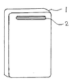
図1−1従来型給湯器本体である。その給湯器の2排気口外部が排気熱利用熱交換器の取り付け部となる。 FIG. 1-1 is a conventional water heater body. The outside of the two exhaust ports of the water heater serves as a mounting portion for the exhaust heat utilization heat exchanger.
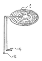
図2−3熱交換器であり高温の排気熱を回収し、本体の給湯作動燃料を減少させる主要部であり4給水入り口結び、5水道管結び口と結合される配管となる。 Fig.2-3 is a heat exchanger, which is a main part that recovers high-temperature exhaust heat and reduces hot water operation fuel of the main body, and is a pipe that is connected to a 4 water supply inlet connection and a 5 water supply pipe connection.
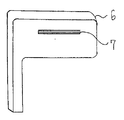
図3−6は排気熱利用熱交換器カバーである。本カバーは図2熱交換器が収納され一体として排気熱利用熱交換器となる、7熱交換器排気口は熱交換器内部が蓄熱の為に穴の大きさが制限される構造とする。 FIG. 3-6 is an exhaust heat utilization heat exchanger cover. This cover has a structure in which the heat exchanger in FIG. 2 is housed and becomes an exhaust heat utilization heat exchanger as a whole. The heat exchanger exhaust port has a structure in which the size of the hole is limited for heat storage inside the heat exchanger.
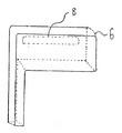
図4は熱交換器カバー裏側の透視図で2排気口に装着される8開口部となる、この裏側8開口部より排気熱がカバー内に吹き入れられる。 FIG. 4 is a perspective view of the back side of the heat exchanger cover, and 8 openings are attached to the 2 exhaust ports. Exhaust heat is blown into the cover from the back side 8 openings.
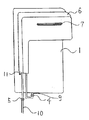
図5は従来型給湯器に排気熱利用熱交換器が装着された図である、4給水入り口結び、5水道管結び口の結合により本機能の完成構成図となる。 FIG. 5 is a view in which an exhaust heat utilization heat exchanger is attached to a conventional hot water heater, and is a completed configuration diagram of this function by combining four water supply inlet ties and five water pipe ties.
本排気熱利用熱交換器の産業上の利用として、商業用では大中小飲食店の給湯利用、工業用として食品製造加工業の給湯利用、大小宿泊施設の給湯利用、そして最大である一般家庭の給湯利用、それに伴う燃料の消費量は膨大なものである。この膨大な燃料削減に排気熱利用熱交換器は十分対処出来る機器であり、産業上の利用可能性は日本国内に留まらず全世界に普及されるものである。
また、本件生産に於いては新たに生産上の物流、販売の流通と大きな経済効果の発生と雇用の促進効果が生ずる。Industrial use of this exhaust heat heat exchanger is for commercial use, hot water supply for large, medium and small restaurants, for industrial use, hot water supply for food manufacturing and processing, hot water use for large and small accommodation facilities, and the largest household The use of hot water and the accompanying fuel consumption are enormous. The exhaust heat heat exchanger is a device that can sufficiently cope with this enormous fuel reduction, and industrial applicability is not limited to Japan, but is spread all over the world.
In addition, this production will produce new production logistics, sales distribution, significant economic effects and employment promotion effects.
1 従来型給湯器
2 従来型給湯器排気口
3 熱交換器
4 給水入り口結び
5 水道管結び口
6 熱交換器カバー
7 熱交換器排気口
8 熱交換器裏側開口部
9 給湯器給水結び口
10 水道管
11 ドレン水結び口DESCRIPTION OF SYMBOLS 1
Claims (1)
Priority Applications (1)
| Application Number | Priority Date | Filing Date | Title |
|---|---|---|---|
| JP2009239823A JP2011069596A (en) | 2009-09-24 | 2009-09-24 | Heat exchanger utilizing exhaust heat |
Applications Claiming Priority (1)
| Application Number | Priority Date | Filing Date | Title |
|---|---|---|---|
| JP2009239823A JP2011069596A (en) | 2009-09-24 | 2009-09-24 | Heat exchanger utilizing exhaust heat |
Publications (1)
| Publication Number | Publication Date |
|---|---|
| JP2011069596A true JP2011069596A (en) | 2011-04-07 |
Family
ID=44015023
Family Applications (1)
| Application Number | Title | Priority Date | Filing Date |
|---|---|---|---|
| JP2009239823A Pending JP2011069596A (en) | 2009-09-24 | 2009-09-24 | Heat exchanger utilizing exhaust heat |
Country Status (1)
| Country | Link |
|---|---|
| JP (1) | JP2011069596A (en) |
-
2009
- 2009-09-24 JP JP2009239823A patent/JP2011069596A/en active Pending
Similar Documents
| Publication | Publication Date | Title |
|---|---|---|
| EP1882891A3 (en) | CO-Generation | |
| WO2017054320A1 (en) | Flue gas waste heat recovery device | |
| EP2006607A3 (en) | Improvements in and relating to water heating | |
| CN104192079B (en) | Ecological bath system | |
| MX374789B (en) | FOURTH GENERATION SYSTEM. | |
| CN204285493U (en) | Wood fuel boiler exhaust gas energy-conserving and environment-protective treatment system | |
| CN207231287U (en) | A kind of boiler exhaust gas thermal energy recycling and purifier | |
| ATE508335T1 (en) | HOT WATER SUPPLY SYSTEM WITH DOUBLE PIPE | |
| EA201100573A1 (en) | WASHING DEVICE | |
| JP2011069596A (en) | Heat exchanger utilizing exhaust heat | |
| CN202648150U (en) | Waste heat recovery device of boiler | |
| DE602008006264D1 (en) | HEATHER, THEREFORE PROVIDED EXHAUST GAS RECOVERY | |
| JP2010281508A5 (en) | ||
| CN105115150A (en) | Fuel gas generating device | |
| CN205002388U (en) | Condensing water heater | |
| CN204943862U (en) | A kind of gasifier section | |
| CN104165349B (en) | Device for utilizing waste of boiler | |
| CN202328306U (en) | Heat recovery and dust reducing device for boiler smoke | |
| CN201964590U (en) | Water heater device | |
| RU2010110305A (en) | GAS GENERATOR INSTALLATION | |
| CN206064038U8 (en) | Flue gas cool-down dust-extraction unit | |
| CN203980245U (en) | Energy-saving combustion gas heat exchange waste heat boiler device | |
| KR20120111691A (en) | Apparatus for reusing waste heat of boiler | |
| CN201724202U (en) | High-efficiency recycling device for waste heat of boiler tail gas | |
| CN203823720U (en) | Heat-pipe waste heat vapor generator |