JP2011069461A - Power transmission belt and method for installing the same - Google Patents
Power transmission belt and method for installing the same Download PDFInfo
- Publication number
- JP2011069461A JP2011069461A JP2009222587A JP2009222587A JP2011069461A JP 2011069461 A JP2011069461 A JP 2011069461A JP 2009222587 A JP2009222587 A JP 2009222587A JP 2009222587 A JP2009222587 A JP 2009222587A JP 2011069461 A JP2011069461 A JP 2011069461A
- Authority
- JP
- Japan
- Prior art keywords
- power transmission
- transmission belt
- laminated
- laminated ring
- ring
- Prior art date
- Legal status (The legal status is an assumption and is not a legal conclusion. Google has not performed a legal analysis and makes no representation as to the accuracy of the status listed.)
- Pending
Links
Images


Landscapes
- Transmissions By Endless Flexible Members (AREA)
Abstract
Description
本発明は、動力伝達用ベルトおよび動力伝達用ベルトの組み付け方法に関し、特に、複数のエレメントを隣接させて配置し、エレメントを並列に配列された無端状の積層リングに組み付けることにより環状に結束して構成した動力伝達用ベルトおよび動力伝達用ベルトの組み付け方法に関する。 The present invention relates to a power transmission belt and a method for assembling the power transmission belt, and in particular, a plurality of elements are arranged adjacent to each other, and the elements are assembled into an endless laminated ring arranged in parallel to be bound in an annular shape. And a method for assembling the power transmission belt.
一般に、複数の回転部材同士の間で動力の伝達を行う場合に用いる変速機として、変速比を段階的に変化させることができる有段変速機と、変速比を連続して、すなわち、無段階に変化させることができる無段変速機とがあり、後者の無段変速機としてはベルト式無段変速機およびトロイダル式無段変速機等が知られている。 In general, as a transmission used when power is transmitted between a plurality of rotating members, a stepped transmission capable of changing a gear ratio stepwise and a gear ratio continuously, that is, steplessly There are continuously variable transmissions that can be changed to the above, and belt-type continuously variable transmissions, toroidal-type continuously variable transmissions, and the like are known as the latter continuously variable transmission.
このうち、ベルト式無段変速機(ベルト式CVT:Continuously Variable Transmission)は、駆動プーリおよび従動プーリの2組のプーリと、駆動プーリおよび従動プーリに巻き掛けられる動力伝達用ベルトとを使用して変速比を無段階に変化させる変速機である。 Of these, the belt type continuously variable transmission (belt type CVT) uses two sets of pulleys, a driving pulley and a driven pulley, and a power transmission belt wound around the driving pulley and the driven pulley. This is a transmission that changes the gear ratio steplessly.
このようなベルト式無段変速機に用いられる動力伝達用ベルトとして、例えば、エレメントあるいはブロック等と称される多数の板片をその板厚方向に互いに重ね合わせて環状に配列するとともに、それらの板片をリング、バンドあるいはキャリア等と称される環状の帯状体で環状に結束することにより、無端状に形成されたベルトが知られている。 As a power transmission belt used in such a belt type continuously variable transmission, for example, a large number of plate pieces called elements or blocks are overlapped with each other in the plate thickness direction and arranged in an annular shape. A belt formed into an endless shape by bundling plate pieces in an annular shape called a ring, band or carrier is known.
このような動力伝達用ベルトが、駆動プーリおよび従動プーリの2組のプーリに巻き掛けられた状態で駆動プーリが駆動されると、エレメントには、エレメントと駆動プーリとの接触部分の摩擦力および駆動プーリのトルクに応じて駆動プーリからエレメントに対して加えられるエレメントの積層方向、すなわち、エレメントの板厚方向の圧縮力(エレメントの押し出し力)が作用する。 When the drive pulley is driven in a state in which such a power transmission belt is wound around two sets of pulleys, that is, a drive pulley and a driven pulley, the element has a frictional force at a contact portion between the element and the drive pulley, and In accordance with the torque of the drive pulley, a compressive force (element push-out force) acts in the element stacking direction applied to the element from the drive pulley, that is, the plate thickness direction of the element.
そして、駆動プーリに接触しているエレメントに伝達された圧縮力は、駆動プーリに巻き掛けられていないエレメントを経由して、従動プーリに接触しているエレメントに伝達される。 Then, the compressive force transmitted to the element in contact with the drive pulley is transmitted to the element in contact with the driven pulley via the element not wound around the drive pulley.
この従動プーリに接触しているエレメントに圧縮力が伝達されると、そのエレメントと従動プーリとの接触部分の摩擦力および伝達された圧縮力に応じて従動プーリを回転させようとするトルクが発生する。このようにして、駆動プーリと従動プーリとの間で動力伝達用ベルトを介して動力伝達が行われる。 When a compressive force is transmitted to the element in contact with the driven pulley, a torque is generated to rotate the driven pulley in accordance with the frictional force of the contact portion between the element and the driven pulley and the transmitted compressive force. To do. In this way, power is transmitted between the drive pulley and the driven pulley via the power transmission belt.
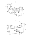
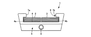
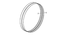
このような従来の動力伝達用ベルトとしては、図12〜図15に示すようなものが知られている(例えば、特許文献1参照)。図12において、動力伝達用ベルト1は、それぞれが無端状のフープを積層してなり、並列に配列される一対の積層リング2、3(図13参照)と、一対の積層リング2、3を並列に収容する凹部4を介して環状に結束された複数のエレメント5(図示1個)とから構成されている。
As such conventional power transmission belts, those shown in FIGS. 12 to 15 are known (see, for example, Patent Document 1). In FIG. 12, the power transmission belt 1 is formed by laminating endless hoops, and includes a pair of laminated
エレメント5は、凹部4における左右の内側面4a、4bからエレメント5の幅方向内方に向かって突出するとともに、並列に配列された積層リング2、3の幅の総和よりも小さい開口6を有し、凹部4内に並列に配列された積層リング2、3に対向する突出部7a、7bを備えており、突出部7a、7bに積層リング2、3が係合することにより、積層リング2、3がエレメント5から外れないように積層リング2、3が凹部4内に収容されている。
The
また、図14に示すようにエレメント5の積層リング2、3の周方向の前後面にはそれぞれディンプル8とホール9とが設けられており、前後のエレメント5同士の間でこれらのディンプル8をホール9に遊嵌させることにより、動力伝達用ベルト1の走行中にエレメント5を整列させるようになっている。
Further, as shown in FIG. 14, dimples 8 and holes 9 are respectively provided on the front and rear surfaces of the laminated
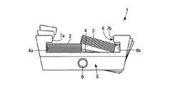
このような構成を有する動力伝達用ベルト1においては、積層リング2、3にエレメント5を組み付ける場合に、並列に配列される積層リング2、3の一部を互いに重ね合わせた状態を実現させる必要がある。
In the power transmission belt 1 having such a configuration, when the
すなわち、図15に示すように、並列に配列された積層リング2、3に対してエレメント5を組み付ける場合には、並列に配列された積層リング2、3のうちの一方の積層リング3にねじりを加えて積層リング2、3の一部を互いに重ね合わせることにより、並列に配列された積層リング2、3の幅の総和をエレメント5の開口6の開口幅よりも小さくする必要がある。
That is, as shown in FIG. 15, when the
ここで、並列に配列された積層リング3にねじりを加えて積層リング2、3の一部を互いに重ね合わせた状態にするためには、隣接しているエレメント5同士を、それぞれの隣接する面で相対回転、すなわち、ローリングさせる必要がある。
Here, in order to twist the stacked
従来のエレメント5では、ホール9を支点としてディンプル8がホール9に対して回動するようにエレメント5同士をローリングさせることにより、積層リング3にねじりを作用させ、積層リング2、3の一部を容易に重ね合わせた状態を設定することができるため、エレメント5を積層リング2、3に容易に組み付けることができる。
In the
しかしながら、このような従来の動力伝達用ベルト1にあっては、並列に配列された積層リング2、3の幅の総和をエレメント5の開口6の開口幅よりも狭くするために、並列に配列された積層リング2、3の一部を互いに重ね合わせる必要があり、このようにした場合には、積層リング2、3が並列に配列された状態に戻ろうとする張力が発生するため、エレメント5を積層リング2、3に組み付ける作業が面倒となって動力伝達用ベルト1の組み付け作業の作業性が低下してしまい、未だ改善の余地がある。
However, such a conventional power transmission belt 1 is arranged in parallel in order to make the sum of the widths of the laminated
また、エレメント5を積層リング2、3に容易に組み付けるためには、エレメント5の開口6の開口幅に対して、並列に配列された積層リング2、3の幅の総和を小さくしたり、エレメント5の開口6の開口幅を並列に配列された積層リング2、3の幅の総和よりも大きくすることが考えられるが、このようにした場合には、動力伝達用ベルトの走行時にエレメント5が積層リング2、3から脱落するおそれがあり、動力伝達用ベルトの信頼性が低下しまうおそれがあった。
In order to easily assemble the
本発明は、上述のような従来の問題を解決するためになされたもので、複数のエレメントを積層リングに容易に組み付けることができ、動力伝達用ベルトの組み付け作業の作業性を向上させることができる動力伝達用ベルトおよび動力伝達用ベルトの組み付け方法を提供することを目的とする。 The present invention has been made to solve the above-described conventional problems, and can easily assemble a plurality of elements to a laminated ring, thereby improving the workability of an assembly work of a power transmission belt. An object of the present invention is to provide a power transmission belt and a method for assembling the power transmission belt.
本発明に係る動力伝達用ベルトは、上記目的を達成するため、(1)無端状のフープを積層してなる積層リングと、前記積層リングを収容する凹部を介して環状に結束された複数のエレメントとを含んで構成される動力伝達用ベルトにおいて、前記複数のエレメントが、前記凹部における左右の内側面の上部から前記エレメントの幅方向内方に向かって突出するとともに、突出方向先端面によって前記凹部の開口を形成し、前記凹部内に収容された前記積層リングに対向する突出部を備え、前記一対の突出部の突出方向先端面を、前記エレメントの板厚方向に対して傾斜させることにより、前記積層リングの周方向と前記突出部の突出方向先端面の傾斜方向とが一致しないときの前記開口の第1の開口幅を前記積層リングの幅よりも小さくするとともに、前記積層リングの周方向と前記突出部の突出方向先端面の傾斜方向とが一致したときの前記開口の第2の開口幅が、前記第1の開口幅に比べて大きくなるようにしたものから構成されている。 In order to achieve the above object, a power transmission belt according to the present invention includes: (1) a plurality of laminated rings formed by laminating endless hoops; In the power transmission belt including the elements, the plurality of elements protrude from the upper portions of the left and right inner side surfaces of the recess toward the inner side in the width direction of the elements, and the protrusion direction front end surface By forming a recess opening, and having a projecting portion facing the laminated ring accommodated in the recess, the projecting direction front end surfaces of the pair of projecting portions are inclined with respect to the plate thickness direction of the element. The first opening width of the opening when the circumferential direction of the laminated ring and the inclined direction of the front end surface of the protruding portion do not coincide with each other is made smaller than the width of the laminated ring. In addition, the second opening width of the opening when the circumferential direction of the laminated ring coincides with the inclination direction of the front end surface of the protruding portion is made larger than the first opening width. Consists of things.
この構成により、一対の突出部の突出方向先端面を、エレメントの板厚方向に対して傾斜させることにより、積層リングの周方向と突出部の突出方向先端面の傾斜方向とが一致しないときの開口の第1の開口幅を積層リングの幅よりも小さくするとともに、積層リングの周方向と突出部の突出方向先端面の傾斜方向とが一致したときの開口の第2の開口幅を第1の開口幅に比べて大きくしたので、積層リングの周方向と突出部の突出方向先端面の傾斜方向とが一致するようにエレメントの板厚方向を積層リングの周方向に対して傾けたときに、第1の開口幅よりも大きい第2の開口幅を通してエレメントを積層リングに容易に組み付けることができる。 With this configuration, the circumferential direction of the laminated ring and the inclined direction of the projecting direction tip surface of the projecting portion do not coincide with each other by inclining the projecting direction tip surfaces of the pair of projecting portions with respect to the plate thickness direction of the element. The first opening width of the opening is made smaller than the width of the laminated ring, and the second opening width of the opening when the circumferential direction of the laminated ring coincides with the inclined direction of the protruding end surface of the protruding portion is the first width. When the thickness direction of the element is tilted with respect to the circumferential direction of the laminated ring so that the circumferential direction of the laminated ring and the inclined direction of the front end surface of the protruding portion coincide with each other. The element can be easily assembled to the laminated ring through the second opening width larger than the first opening width.
また、積層リングの周方向と前記突出部の突出方向先端面の傾斜方向とが一致しないようにエレメントの板厚方向と積層リングの周方向を一致させたときに、積層リングに対して開口の第1の開口幅を積層リングの幅よりも小さくすることができるため、凹部に収容された積層リングを突出部に係合させることができ、エレメントが積層リングから脱落してしまうのを確実に防止することができる。
この結果、複数のエレメントを積層リングに容易に組み付けることができ、動力伝達用ベルトの組み付け作業の作業性を向上させることができる。
Also, when the plate thickness direction of the element and the circumferential direction of the laminated ring are matched so that the circumferential direction of the laminated ring does not coincide with the inclined direction of the protruding end surface of the protruding portion, the opening of the laminated ring is Since the first opening width can be made smaller than the width of the laminated ring, the laminated ring accommodated in the recess can be engaged with the protruding portion, and the element can be reliably removed from the laminated ring. Can be prevented.
As a result, a plurality of elements can be easily assembled to the laminated ring, and the workability of the assembly work of the power transmission belt can be improved.
上記(1)に記載の動力伝達用ベルトにおいて、(2)前記凹部における左右の内側面が、前記突出部の突出方向先端面と同方向に傾斜しているものから構成されている。
この構成により、凹部における左右の内側面を突出部の突出方向先端面と同方向に傾斜させたので、積層リングの周方向と突出部の突出方向先端面の傾斜方向とが一致するようにエレメントの板厚方向を積層リングの周方向に対して傾けた状態で、エレメントを積層リングに組み付けたときに、凹部の左右の内側面が積層リングに引っ掛かるのを防止して、積層リングをエレメントの凹部に確実に収容することができる。
In the power transmission belt described in (1) above, (2) the left and right inner surfaces of the recess are inclined in the same direction as the front end surface in the protruding direction of the protruding portion.
With this configuration, the left and right inner surfaces of the recess are inclined in the same direction as the protruding direction front end surface of the protruding portion, so that the circumferential direction of the laminated ring and the inclined direction of the protruding end surface of the protruding portion coincide with each other. When the element is assembled to the laminated ring with the plate thickness direction tilted with respect to the circumferential direction of the laminated ring, the left and right inner surfaces of the recess are prevented from being caught by the laminated ring. It can be reliably accommodated in the recess.
上記(1)または(2)に記載の動力伝達用ベルトにおいて、(3)前記凹部における左右の内側面の上部の開口の開口幅が、前記積層リングの幅よりも大きく形成される少なくとも1個以上の解放型エレメントを有するものから構成されている。 (1) In the power transmission belt according to (1) or (2), (3) at least one formed so that an opening width of an upper opening of left and right inner surfaces of the recess is larger than a width of the laminated ring. It is comprised from what has the above open | release type element.
このようにしたのは、突出部を有するエレメントを積層リングに組み付けた後、最後の1個または数個のエレメントを積層リングに組み付ける場合に、エレメントの間隔が小さくなってエレメント間の小さい隙間内において、最後のエレメントを積層リングに対して傾けることなく組み付けることができるようにするためである。 This is because when the last one or several elements are assembled to the laminated ring after the element having the protrusion is assembled to the laminated ring, the distance between the elements becomes small and the gap between the elements is small. This is because the last element can be assembled without being inclined with respect to the laminated ring.
すなわち、本発明では、エレメントの凹部における左右の内側面の上部の開口の開口幅が、積層リングの幅よりも大きく形成される解放型エレメントを積層リングに最後に組み付けることで、解放型エレメントを傾けることなく隙間の小さいエレメント間に解放型エレメントを組み付けることができる。このため、複数のエレメントの最後のエレメントを積層リングに容易に組み付けることができ、動力伝達用ベルトの組み付け作業の作業性をより一層向上させることができる。 That is, in the present invention, the release type element is formed by assembling the release type element having the opening width of the upper part of the left and right inner side surfaces in the concave portion of the element larger than the width of the lamination ring at the end, so that An open element can be assembled between elements with a small gap without tilting. For this reason, the last element of a some element can be easily assembled | attached to a lamination | stacking ring, and the workability | operativity of the assembly | attachment operation | work of the power transmission belt can be improved further.
上記(3)に記載の動力伝達用ベルトにおいて、(4)前記解放型エレメントが、前記解放型エレメントに隣接する突出部を有する前記エレメントまたは前記解放型エレメントに対して前記積層リングの径方向に所定距離以上移動するのを規制する規制手段を有するものから構成されている。 In the power transmission belt according to (3) above, (4) the release-type element has a protrusion adjacent to the release-type element or the release-type element in a radial direction of the laminated ring. It is comprised from what has the control means which controls moving beyond a predetermined distance.
この構成により、解放型エレメントが、解放型エレメントに隣接する突出部を有するエレメントまたは解放型エレメントに対して積層リングの径方向に所定距離以上移動するのを規制することができるため、解放型エレメントが積層リングから脱落するのを防止することができ、動力伝達用ベルトの信頼性が低下するのを防止することができる。 With this configuration, the release type element can be restricted from moving more than a predetermined distance in the radial direction of the laminated ring with respect to the element having the protrusion adjacent to the release type element or the release type element. Can be prevented from falling off the laminated ring, and the reliability of the power transmission belt can be prevented from being lowered.
上記(1)ないし(4)に記載の前記エレメントを前記積層リングに組み付ける動力伝達用ベルトの組み付け方法において、(5)前記積層リングの周方向と前記突出部の突出方向先端面の傾斜方向とが一致するように前記積層リングの周方向に対して前記エレメントの板厚方向を傾けた状態で、前記エレメントの凹部に前記積層リングが収容されるように前記エレメントを前記積層リングに組み付け、次いで、前記積層リングの周方向と前記突出部の突出方向先端面の傾斜方向とがずれるように前記エレメントの板厚方向と前記積層リングの周方向とを一致させるようにした。 In the method of assembling the power transmission belt for assembling the element according to the above (1) to (4) to the laminated ring, (5) the circumferential direction of the laminated ring and the inclination direction of the front end surface in the protruding direction of the protruding portion; In the state where the plate thickness direction of the element is inclined with respect to the circumferential direction of the laminated ring so as to match, the element is assembled to the laminated ring so that the laminated ring is accommodated in the concave portion of the element, The plate thickness direction of the element and the circumferential direction of the laminated ring are made to coincide with each other so that the circumferential direction of the laminated ring and the inclined direction of the front end surface in the protruding direction of the protruding portion are shifted.
この方法により、積層リングの周方向と突出部の突出方向先端面の傾斜方向とが一致するようにエレメントの板厚方向を積層リングの周方向に対して傾けたときに、第1の開口幅よりも大きい第2の開口幅を通してエレメントを積層リングに容易に組み付けることができる。 By this method, the first opening width is obtained when the plate thickness direction of the element is tilted with respect to the circumferential direction of the laminated ring so that the circumferential direction of the laminated ring and the inclined direction of the front end surface of the protruding portion coincide with each other. The element can easily be assembled to the laminated ring through a larger second opening width.
また、積層リングの周方向と前記突出部の突出方向先端面の傾斜方向とが一致しないようにエレメントの板厚方向と積層リングの周方向を一致させたときに、積層リングに対して開口の第1の開口幅を積層リングの幅よりも小さくすることができるため、凹部に収容された積層リングを突出部に係合させることができ、エレメントが積層リングから脱落してしまうのを確実に防止することができる。 Also, when the plate thickness direction of the element and the circumferential direction of the laminated ring are matched so that the circumferential direction of the laminated ring does not coincide with the inclined direction of the protruding end surface of the protruding portion, the opening of the laminated ring is Since the first opening width can be made smaller than the width of the laminated ring, the laminated ring accommodated in the recess can be engaged with the protruding portion, and the element can be reliably removed from the laminated ring. Can be prevented.
上記(5)に記載の前記エレメントを前記積層リングに組み付ける動力伝達用ベルトの組み付け方法において、(6)前記積層リングに最後にエレメントを組み付ける際に、前記解放型エレメントの凹部に前記積層リングが収容されるように前記解放型エレメントを前記積層リングに組み付けるようにした。 In the assembling method of the power transmission belt for assembling the element described in (5) above to the laminated ring, (6) when the element is finally assembled to the laminated ring, the laminated ring is placed in the recess of the release type element. The release element is assembled to the laminated ring so as to be accommodated.
この方法により、最後のエレメントの組み付け作業時に、解放型エレメントを傾けることなく隙間の小さいエレメント間に解放型エレメントを組み付けることができる。このため、複数のエレメントの最後のエレメントを積層リングに容易に組み付けることができ、動力伝達用ベルトの組み付け作業の作業性をより一層向上させることができる。 By this method, it is possible to assemble the release-type elements between the elements having a small gap without tilting the release-type elements during the last element assembly operation. For this reason, the last element of a some element can be easily assembled | attached to a lamination | stacking ring, and the workability | operativity of the assembly | attachment operation | work of the power transmission belt can be improved further.
本発明によれば、複数のエレメントを積層リングに容易に組み付けることができ、動力伝達用ベルトの組み付け作業の作業性を向上させることができる動力伝達用ベルトおよび動力伝達用ベルトの組み付け方法を提供することができる。 According to the present invention, there are provided a power transmission belt and a power transmission belt assembling method capable of easily assembling a plurality of elements to a laminated ring and improving workability of the power transmission belt. can do.
以下、本発明に係る動力伝達用ベルトの実施の形態について、図面を用いて説明する。
(第1の実施の形態)
図1〜図8は、本発明に係る動力伝達用ベルトおよび動力伝達用ベルトの組み付け方法の第1の実施の形態を示す図である。
Hereinafter, embodiments of a power transmission belt according to the present invention will be described with reference to the drawings.
(First embodiment)
1 to 8 are views showing a first embodiment of a power transmission belt and a method of assembling the power transmission belt according to the present invention.
まず、構成を説明する。
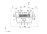
図1、図2において、駆動プーリ11は、駆動プーリ11の駆動軸11aに平行な方向に移動可能な可動シーブ12と、固定軸11aに固定された固定シーブ13とを含んで構成されており、可動シーブ12に形成されたシーブ面12aと固定シーブ13に形成されたシーブ面13aとの間に動力伝達用ベルト14が挟持されている。
First, the configuration will be described.
1 and 2, the
可動シーブ12のシーブ面12aおよび固定シーブ13のシーブ面13aは、シーブ面12a、13a同士の間隔が駆動プーリ11の径方向内側ほど狭くなるとともに、駆動プーリ11の径方向外側ほど広くなるように、駆動プーリ11の径方向に対して傾斜しており、このシーブ面12a、13aによって駆動プーリ11のV溝が構成されている。なお、従動プーリ15についても駆動プーリ11と同様の構成である。
The
可動シーブ12には、可動シーブ12に供給される油圧力によって駆動軸11aに平行な方向の推力が作用するようになっており、この推力によって、可動シーブ12が駆動軸11aに平行な方向に移動することで、シーブ面12aとシーブ面13aの間隔が変化するとともに、動力伝達用ベルト14がシーブ面12a、13aに対して駆動プーリ11の径方向に摺動する。
A thrust in a direction parallel to the
ベルト式無段変速機は、この動力伝達用ベルト14の駆動プーリ11の径方向の摺動によって、動力伝達用ベルト14の駆動プーリ11および従動プーリ15への掛かり径が連続的に変化することで、変速比が連続的に変化する。
In the belt type continuously variable transmission, the diameters of the
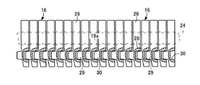
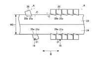
動力伝達用ベルト14は、多数のエレメント16を備えており、このエレメント16は、例えば、金属製の板片状の部材から構成されている。また、エレメント16は、エレメント16の幅方向(図2のX軸方向)の左右の側面17、18がテーパ状に傾斜した面として形成された本体19を有し、そのテーパ状に傾斜した側面17、18がベルト式無段変速機の駆動プーリ11のシーブ面12a、13aあるいは従動プーリ15のシーブ面に摩擦接触することにより、駆動プーリ11から従動プーリ15にトルクを伝達するようになっている。
The
エレメント16の本体19の幅方向(図2のX軸方向)における左右の両端部分にはエレメント16の上下方向(図2のY軸方向)で本体19から上方に延びた左右の柱部20、21がそれぞれ形成されており、本体19の上側のエッジ部分である上端面19aと、柱部20、21の本体19の幅方向における中央を向いた左右の内側面20a、21aとによって、エレメント16の上側(図2のY軸方向での上側)、すなわち、動力伝達用ベルト14の外周側に開口した凹部22が形成されている。このため、内側面20a、21aは凹部22の内側面を構成している。
Left and
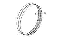
凹部22は、互いに密着して環状に配列されたエレメント16を環状に結束するための無端状の積層リング23、24(図4参照)を並列に配列して収容するようになっており、上端面19aが、積層リング23、24の内周面を接触させて載置するためのサドル面を構成している。
The
積層リング23、24は、例えば、金属製の環状のフープを径方向に複数枚積層させて形成したものから構成されており、積層リング23、24は、互いに材質、強度および周長(具体的には最内周面の周長)が等しいものから構成されている。本実施の形態では、エレメント16および積層リング23、24が動力伝達用ベルト14を構成している。
The laminated rings 23 and 24 are constituted by, for example, a structure in which a plurality of metal annular hoops are laminated in the radial direction, and the
柱部20、21の上端部分には、柱部20、21から本体19の幅方向内方に向かって突出する突出部としての抜け止め部25、26が形成されており、この抜け止め部25、26は、凹部22に収容された積層リング23、24に対向するとともに、先端面(突出方向先端面)25a、26aによって凹部22の開口27を形成している。
At the upper end portions of the
この動力伝達用ベルト14を構成する多数のエレメント16は、環状に配列された状態で積層リング23、24によって結束されており、この結束された状態で駆動プーリ11および従動プーリ15に巻き掛けられている。したがって、駆動プーリ11および従動プーリ15に巻き掛けられた状態では、各エレメント16が、駆動プーリ11および従動プーリ15の中心に対して扇状に拡がり、かつ互いに密着する必要があるため、各エレメント16の図2中、下方部分(環状に配列した状態での中心側の部分)が薄肉に形成されている。
A large number of
すなわち、本体19の一方の面(例えば、図3における左側の面)における上端面19aより所定寸法下がった(オフセットされた)部分から下側の部分が削り落とされた状態で次第に薄肉化されている。したがって、各エレメント16が扇形に拡がって接触する状態、言い換えると、各エレメント16が駆動プーリ11および従動プーリ15に巻き掛かり円弧状に湾曲して配列されて動力伝達用ベルト14が湾曲する状態で、その板厚の変化する境界部分で接触する。
That is, the thickness of the
この境界部分のエッジが、所謂、ロッキングエッジ28となっており、各エレメント16が円弧状に湾曲した配列状態となった場合に、ロッキングエッジ28が隣接する他のエレメント16に接触する。
The edge of the boundary portion is a so-called
また、エレメント16の本体19の幅方向における中央部分には、各エレメント16が駆動プーリ11および従動プーリ15に巻き掛からず直線状に配列される直線状態において各エレメント16の相対的な位置を決めるためのディンプル29とホール30とが形成されている。
Further, at the central portion of the
具体的には、本体19の一方の面側(図3の例では、ロッキングエッジ28のある面側)に凸となる円錐台形のディンプル29が形成されており、このディンプル29とは反対側の面に、隣接するエレメント16におけるディンプル29を遊嵌させる有底円筒状のホール30が形成されている。ここで、遊嵌とは、ディンプル29とホール30の間に隙間が画成されるようにディンプル29をホール30に緩く嵌合させることである。
Specifically, a
したがって、動力伝達用ベルト14の直線状態でディンプル29をホール30に遊嵌することによって、その状態におけるエレメント16同士の図2での左右方向および上下方向の相対位置を決めることができ、例えば、ベルト式無段変速機が運転される場合に、動力伝達用ベルト14のがたつきを防止して動力伝達用ベルト14を安定して走行させることができる。
Therefore, by loosely fitting the
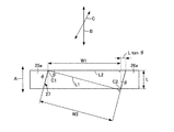
一方、図1、図5に示すように、本実施の形態のエレメント16の抜け止め部25、26の先端面25a、26aは、エレメント16の板厚方向Aに対して所定角度だけ傾斜しており、柱部20、21の内側面20a、21aは、抜け止め部25、26の先端面25a、26aの傾斜方向と同方向に傾斜している。
したがって、図5(b)に示すように、積層リング23、24は、柱部20、21のエッジ部20b、21bに当接するようにして凹部22に収容されることになる。
On the other hand, as shown in FIGS. 1 and 5, the tip end surfaces 25 a and 26 a of the retaining
Therefore, as shown in FIG. 5B, the laminated rings 23 and 24 are accommodated in the
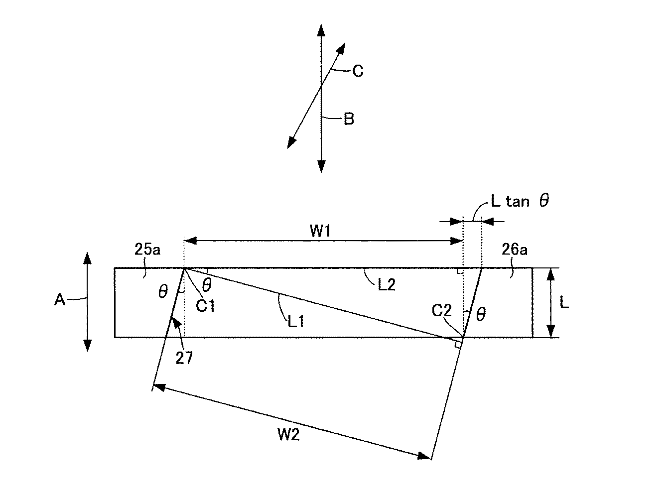
本実施の形態では、抜け止め部25、26の先端面25a、26aをエレメント16の板厚方向Aに対してθ(所定角度に相当)だけ傾斜させることにより、図6に示すように、積層リング23、24の周方向Bと抜け止め部25、26の先端面25a、26aの傾斜方向とが一致しないときの開口27の第1の開口幅W1を積層リング23、24の幅の総和(以下、リング幅W0という、図2参照)よりも小さくするとともに、積層リング23、24の周方向Bと抜け止め部25、26の先端面25a、26aの傾斜方向Cとが一致したときの開口27の第2の開口幅W2が、第1の開口幅W1に比べて大きくなるようにしている。
In the present embodiment, the end faces 25a, 26a of the retaining
具体的には、図6において、積層リング23、24の周方向Bと抜け止め部25、26の先端面25a、26aの傾斜方向Cとが一致しないときの開口27の開口幅(第1の開口幅)W1は、抜け止め部25、26の先端面25a、26aのエッジC1、C2を結んだ直線のエレメント16の幅方向の距離に相当し、積層リング23、24の周方向Bと抜け止め部25、26の先端面25a、26aの傾斜方向Cとが一致したときの開口27の開口幅(第2の開口幅)W2は、先端面25aと先端面26aとの距離W2に相当する。
Specifically, in FIG. 6, the opening width of the opening 27 (the first width when the circumferential direction B of the laminated rings 23, 24 and the inclined direction C of the tip surfaces 25a, 26a of the retaining
このとき、先端面25aと先端面26aとは平行であり、先端面25a、26aがエレメント16の板厚方向Aに対して傾斜しているため、エレメント16の板厚方向Aに対する先端面25a、26aの傾斜角度はθとなる。また、エッジC1から先端面26aに向かい先端面25aに垂直な線L1とエレメント16の幅方向の線L2との交点の角度はθとなる。したがって、エレメント16の板厚方向に対する先端面25a、26aの傾斜角度θと、仮想線の交点の角度θとは、同じ角度となる。そのため、開口27の第1の開口幅W1と第2の開口幅W2の関係がW1<W2となる条件を求めると、下記の式(1)で表される。
次に、動力伝達用ベルト14の組み付け方法を説明する。
図7、図8に示すように、積層リング23、24を並列に配列し、積層リング23、24の周方向Bとエレメント16の抜け止め部25、26の先端面25a、26aの傾斜方向とが一致するようにエレメント16を傾ける。このときに、図6に示すように、エレメント16の開口27の開口幅W2が開口幅W1よりも大きくなるため、積層リング23、24のリング幅W0に対して積層リング23、24の開口幅W2を開口幅W1に対して大きくすることができる。
Next, a method for assembling the
As shown in FIGS. 7 and 8, the laminated rings 23 and 24 are arranged in parallel, and the circumferential direction B of the laminated rings 23 and 24 and the inclination directions of the front end surfaces 25 a and 26 a of the retaining
この状態で、図7に示すように、エレメント16の開口27を通して凹部22に積層リング23、24に挿通する。このときには、片側の柱部20の抜け止め部25の先端面25aを積層リング23側に摺接させて柱部20の内側面20aを積層リング23の側面を当接させる。この柱部20の内側面20aが抜け止め部25の先端面25aの傾斜方向Cと同方向に傾斜しているため、柱部20の内側面20aに積層リング23の側面が引っ掛かることがなく、エレメント16が傾斜した姿勢を維持する。
In this state, as shown in FIG. 7, the laminated rings 23 and 24 are inserted into the
次いで、柱部21の抜け止め部26の先端面26aを積層リング24側に摺接させ、エレメント16の凹部22に積層リング23、24が収容されるようにエレメント16を積層リング23、24に組み付ける。
Next, the
次いで、積層リング23、24の周方向Bと抜け止め部25、26の先端面25a、26aの傾斜方向Cとがずれるようにエレメント16の板厚方向Aと積層リング23、24の周方向Bとを一致させる。このとき、抜け止め部25、26に積層リング23、24が係合可能となり、積層リング23、24が凹部22から抜け出てしまうのを防止することができる。
次いで、ディンプル29をホール30(図3参照)に遊嵌して、今回、積層リング23、24に組み付けられたエレメント16を先に組み付けられた隣接するエレメント16に取付ける。
Next, the plate thickness direction A of the
Next, the
なお、本実施の形態では、エレメント16を1個ずつ積層リング23、24に組み付けているが、2個以上纏めて組み付けるようにしてもよい。
In this embodiment, the
このように本実施の形態では、エレメント16の抜け止め部25、26の先端面25a、26aを、エレメント16の板厚方向Aに対して傾斜させることにより、積層リング23、24の周方向Bと抜け止め部25、26の先端面25a、26aの傾斜方向Cとが一致しないときの開口27の第1の開口幅W1を積層リング23、24のリング幅W0よりも小さくするとともに、積層リング23、24の周方向Bと抜け止め部25、26の先端面25a、26aの傾斜方向Cとが一致したときの開口27の第2の開口幅W2が、第1の開口幅W1に比べて大きくなるようにした。
As described above, in the present embodiment, the front end surfaces 25a and 26a of the retaining
そして、積層リング23、24の周方向Bと抜け止め部25、26の先端面25a、26aの傾斜方向Cとが一致するようにエレメント16を傾けた状態で、エレメント16の凹部22に積層リング23、24が収容されるようにエレメント16を積層リング23、24に組み付け、次いで、積層リング23、24の周方向Bと抜け止め部25、26の先端面25a、26aの傾斜方向Cとがずれるようにエレメント16の板厚方向Aと積層リング23、24の周方向Bとを一致させるようにして動力伝達用ベルト14を組み付けるようにした。
このため、積層リング23、24の周方向Bと抜け止め部25、26の先端面25a、26aの傾斜方向Cとが一致するようにエレメント16を積層リング23、24の周方向Bに対して傾けたときに、積層リング23、24のリング幅W0に対して開口27の第2の開口幅W2を大きくすることができ、エレメント16を積層リング23、24に容易に組み付けることができる。
Then, in a state where the
For this reason, the
また、積層リング23、24の周方向Bと抜け止め部25、26の先端面25a、26aの傾斜方向Cとが一致しないようにエレメント16の板厚方向Aと積層リング23、24の周方向Bを一致させたときに、積層リング23、24に対して開口27の第1の開口幅W1を積層リング23、24のリング幅W0よりも小さくすることができるため、凹部22に収容された積層リング23、24を抜け止め部25、26に係合させることができ、エレメント16が積層リング23、24から脱落してしまうのを確実に防止することができる。
Further, the thickness direction A of the
この結果、複数のエレメント16を積層リング23、24に容易に組み付けることができ、動力伝達用ベルト14の組み付け作業の作業性を向上させることができる。
As a result, the plurality of
また、本実施の形態では、凹部22における左右の内側面20a、21aを、抜け止め部25、26の先端面25a、26aと同方向に傾斜させたので、積層リング23、24の周方向Bと抜け止め部25、26の先端面25a、25bの傾斜方向Cとが一致するようにエレメント16を積層リング23、24の周方向Bに対して傾けた状態で、エレメント16を積層リング23、24に組み付けたときに、凹部22の左右の内側面20a、21aが積層リング23、24に引っ掛かるのを防止して、積層リング23、24をエレメント16の凹部22に確実に収容することができる。
Further, in the present embodiment, the left and right
なお、本実施の形態では、並列に配列されるように一対の積層リング23、24から構成しているが、積層リングは、1個であってもよい。この場合には、1個の積層リングのリング幅は、積層リング23、24のリング幅W0と同一幅となる。
In addition, in this Embodiment, although comprised from a pair of lamination | stacking
(第2の実施の形態)
図9〜図11は、本発明に係る動力伝達用ベルトおよび動力伝達用ベルトの組み付け方法の第2の実施の形態を示す図であり、第1の実施の形態と同一の構成には同一番号を付して説明を省略する。
(Second Embodiment)
FIGS. 9-11 is a figure which shows 2nd Embodiment of the assembly method of the power transmission belt and power transmission belt which concern on this invention, and the same number is attached to the same structure as 1st Embodiment. The description is omitted.
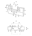
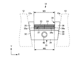
動力伝達用ベルト14は、エレメント16以外のエレメントとして、図1に示す解放型エレメント31を備えている。図9、図10に示すように、解放型エレメント31は、3個設けられており、この解放型エレメント31は、例えば、金属製の板片状の部材から構成されている。
The
また、解放型エレメント31は、解放型エレメント31の幅方向(図9のX軸方向)の左右の側面32、33がテーパ状に傾斜した面として形成された本体34を有し、そのテーパ状に傾斜した側面32、33がベルト式無段変速機の駆動プーリ11のシーブ面12a、13aあるいは従動プーリ15のシーブ面に摩擦接触するようになっている。
Further, the
解放型エレメント31の本体34の幅方向(図9のX軸方向)における左右の両端部分には解放型エレメント31の上下方向(図9のY軸方向)で本体34から上方に延びた左右の柱部35、36がそれぞれ形成されており、本体34の上側のエッジ部分である上端面34aと、柱部35、36の本体34の幅方向における中央を向いた左右の内側面35a、36aとによって、解放型エレメント31の上側(図9のY軸方向での上側)、すなわち、動力伝達用ベルト14の外周側に開口した凹部37が形成されている。
The left and right ends of the
凹部37は、互いに密着して環状に配列された解放型エレメント31を環状に結束するための無端状の積層リング23、24を並列に配列して収容するようになっており、上端面34aが積層リング23、24の内周面を接触させて載置するためのサドル面を構成している。本実施の形態では、エレメント16、解放型エレメント31および積層リング23、24が動力伝達用ベルト14を構成している。
The
また、柱部35、36の上端部分には、凹部37の開口38が形成されている。すなわち、本実施の形態の解放型エレメント31は、凹部37における左右の柱部35、36の内側面35a、36aに形成された開口38を通して積層リング23、24を並列に収容する凹部37を備えている。
In addition, an
また、凹部37の開口38の開口幅W3は、凹部22内に並列に配列された積層リング23、24のリング幅W0よりも大きくなっている。
Further, the opening width W3 of the
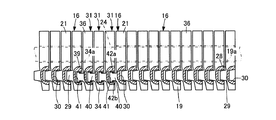
この動力伝達用ベルト14を構成する多数の解放型エレメント31は、環状に配列された状態で積層リング23、24によって結束され、エレメント16と共に駆動プーリ11および従動プーリ15に巻き掛けられる。
A number of release-
したがって、駆動プーリ11および従動プーリ15に巻き掛けられた状態では、各解放型エレメント31が、エレメント16と共に駆動プーリ11および従動プーリ15の中心に対して扇状に拡がり、エレメント16に、または、互いに密着する必要があるため、各解放型エレメント31の図9中、下方部分(環状に配列した状態での中心側の部分)が薄肉に形成されている。
Therefore, in the state of being wound around the
すなわち、本体34の一方の面(例えば、図10における左側の面)における上端面34aより所定寸法下がった(オフセットされた)部分から下側の部分が削り落とされた状態で次第に薄肉化されている。したがって、各解放型エレメント31が駆動プーリ11および従動プーリ15に巻き掛かり円弧状に湾曲して配列されて動力伝達用ベルト14が湾曲する状態で、その板厚の変化する境界部分で接触する。
That is, the thickness of the
この境界部分のエッジが、ロッキングエッジ39となっており、各解放型エレメント31が円弧状に湾曲した配列状態となった場合に、ロッキングエッジ39が隣接する他の解放型エレメント31またはエレメント16に接触する。
The edge of the boundary portion is a locking
一方、解放型エレメント31の本体34の幅方向における中央部分には、各解放型エレメント31が駆動プーリ11および従動プーリ15に巻き掛からず直線状に配列される直線状態において各解放型エレメント31の相対的な位置を決めるためのディンプル40とホール41とが形成されている。
On the other hand, in the central portion of the
具体的には、本体34の一方の面側(図10の例では、ロッキングエッジ39のある面側)に凸となる円錐台形のディンプル40が形成されており、このディンプル40とは反対側の面(他方の面)に、隣接する解放型エレメント31またはエレメント16におけるディンプル29またはディンプル40を遊嵌させる有底円筒状のホール41が形成されている。
Specifically, a
したがって、動力伝達用ベルト14の直線状態でディンプル29、40がホール30、41に遊嵌することによって、その状態における解放型エレメント31同士の図9での左右方向および上下方向の相対位置を決めることができ、例えば、ベルト式無段変速機が運転される場合に、動力伝達用ベルト14のがたつきを防止して動力伝達用ベルト14を安定して走行させることができる。
Therefore, when the
また、ディンプル40は、図11(a)に示すように、小径の第1の軸部40aと、第1の軸部40aの先端から突出し、第1の軸部40aよりも大径でかつ、突出方向先端に行くに従って漸次小径となる第2の軸部40bとから構成されており、このディンプル40は、解放型エレメント31の一方の面と図10中、右端に設けられた解放型エレメント31に隣接するエレメント16の一方の面に形成されている。また、ホール41は、左端に設けられた解放型エレメント31に隣接するエレメント16の他方に形成されている。
In addition, as shown in FIG. 11A, the
このため、ディンプル40がホール41に遊嵌された状態では、解放型エレメント31が隣接する解放型エレメント31またはエレメント16に対して積層リング23、24の径方向に所定距離以上移動することが規制される。本実施の形態では、ディンプル40およびホール41が規制手段を構成している。
For this reason, in a state where the
ここで、解放型エレメント31が隣接する解放型エレメント31またはエレメント16に対して積層リング23、24の径方向に移動できる所定距離とは、ホール41とディンプル40の隙間の距離に対応するものとなる。
Here, the predetermined distance at which the
図11(b)に示すように、ホール41内には一対のバネ部材42a、42bが設けられており、このバネ部材42a、42bの両端部は、ホール41の内周面に嵌合している。また、バネ部材42a、42bは、ディンプル40の第2の軸部40bの最大直径よりも短い距離でホール41の径方向に一定距離だけ離隔しており、この一定距離だけ離隔した初期位置と初期位置からホール41の径方向外方に離隔した離隔位置との間で弾性変形自在となっている。
As shown in FIG. 11 (b), a pair of
次に、動力伝達用ベルト14の組み付け方法を説明する。
エレメント16の組み付けが満遍なく行われ、最後のエレメント16を積層リング23、24に組み付ける場合には、エレメント16の間の隙間が小さくなってしまい、エレメント16を傾けて積層リング23、24に組み付け難くなる。
Next, a method for assembling the
When the
本実施の形態では、このように最後のエレメント16を積層リング23、24に組み付ける状況になったときに、積層リング23、24のリング幅W0よりも大きい開口38を有する解放型エレメント31を使用する。
In the present embodiment, when the
まず、解放型エレメント31のディンプル40をホール41に遊嵌させるようにして3個の解放型エレメント31を板厚方向に重ね合わせる。本実施の形態では、ディンプル40をホール41に遊嵌させるときに、先細り形状となっている第2の軸部40bの最大直径の部位がホール41内のバネ部材42a、42bを通過する際に、バネ部材42a、42bを初期位置から離隔位置に弾性変形させた後、第2の軸部40bよりも小径の第1の軸部40aがバネ部材42a、42bを通過したときにバネ部材42a、42bが離隔位置から初期位置に弾性変形して、第2の軸部40bの最大直径よりも短い距離でホール41の径方向に一定距離だけ離隔する。
First, the three release-
このため、バネ部材42a、42bに第1の軸部40aを挟み込ませて第2の軸部40bをバネ部材42a、42bに引っ掛けることができ、ディンプル40をホール41に抜け止め係止させて、解放型エレメント31が隣接する解放型エレメント31から抜け出てしまうのを防止することができる。
For this reason, the
次いで、積層リング23、24を並列に配列した状態で3個に纏められた解放型エレメント31の凹部37が積層リング23、24の下方に位置するようにして解放型エレメント31を積層リング23、24の下方に位置させる。
Next, the
次いで、積層リング23、24を凹部37に収容するようにして解放型エレメント31を積層リング23、24に組み付ける。このとき、図10中、右端の解放型エレメント31に隣接するエレメント16のディンプル40を解放型エレメント31のホール41に遊嵌させるとともに、図3中、左端の解放型エレメント31に隣接するエレメント16のホール41に解放型エレメント31のディンプル40を遊嵌させる。
Next, the
このとき、バネ部材42a、42bに第1の軸部40aを挟み込ませて第2の軸部40bをバネ部材42a、42bに引っ掛けることができるので、ディンプル40をホール41に抜け止め係止させて、解放型エレメント31が隣接する解放型エレメント31またはエレメント16から抜け出てしまうのを防止することができる。また、この状態において、解放型エレメント31が隣接する解放型エレメント31またはエレメント16に対して積層リング23、24の径方向に所定距離以上移動しない。
このように本実施の形態では、積層リング23、24のリング幅W0よりも開口幅W3が大きい開口を有する3個の解放型エレメント31を設け、エレメント16の組み付けが終了した後、最後の解放型エレメント31の組み付け作業時に、解放型エレメント31を傾けることなく隙間の小さいエレメント16間に解放型エレメント31を組み付けることができる。このため、最後に解放型エレメント31を積層リング23、24に容易に組み付けることができ、動力伝達用ベルト14の組み付け作業の作業性をより一層向上させることができる。
At this time, the
As described above, in the present embodiment, three release-
また、本実施の形態では、解放型エレメント31が、解放型エレメント31に隣接する解放型エレメント31またはエレメント16に対して積層リング23、24の径方向に所定距離以上移動するのを規制するディンプル40とホール41とを設けたので、ディンプル40をホール41に遊嵌させることによって、開口27の開口幅W1および開口幅W2よりも開口幅W3が大きい開口38を有する解放型エレメント31が、解放型エレメント31に隣接する解放型エレメント31またはエレメント16に対して積層リング23、24の径方向に所定距離以上移動しないようにすることができる。このため、解放型エレメント31が積層リング23、24から脱落するのを防止することができ、動力伝達用ベルト14の信頼性が低下するのを防止することができる。
Further, in the present embodiment, the dimple that restricts the
なお、本実施の形態では、3個の解放型エレメント31を設けているが、解放型エレメント31は、1個以上あればよい。
In the present embodiment, three release-
また、今回開示された実施の形態は、全ての点で例示であってこの実施の形態に制限されるものではない。本発明の範囲は、上記した実施の形態のみの説明ではなくて特許請求の範囲によって示され、特許請求の範囲と均等の意味および範囲内での全ての変更が含まれることが意図される。 The embodiment disclosed this time is illustrative in all respects and is not limited to this embodiment. The scope of the present invention is shown not by the above description of the embodiments but by the scope of the claims, and is intended to include all modifications within the meaning and scope equivalent to the scope of the claims.
以上のように、本発明に係る動力伝達用ベルトおよび動力伝達用ベルトの組み付け方法は、複数のエレメントを積層リングに容易に組み付けることができ、動力伝達用ベルトの組み付け作業の作業性を向上させることができるという効果を有し、複数のエレメントを隣接させて配置し、エレメントを並列に配列された無端状の積層リングに組み付けることにより環状に結束して構成した動力伝達用ベルトおよび動力伝達用ベルトの組み付け方法等として有用である。 As described above, the power transmission belt and the power transmission belt assembly method according to the present invention can easily assemble a plurality of elements to the laminated ring, and improve the workability of the power transmission belt assembly operation. A power transmission belt and a power transmission belt, in which a plurality of elements are arranged adjacent to each other, and the elements are assembled into an endless laminated ring arranged in parallel to form an annular bundle. This is useful as a belt assembly method.
14 動力伝達用ベルト
16 エレメント
20a、21a 内側面
22 凹部
23、24 積層リング
25、26 抜け止め部(突出部)
25a、26a 先端面(突出方向先端面)
27 開口
31 解放型エレメント
35a、36a 内側面
37 凹部
38 開口
40 ディンプル(規制手段)
41 ホール(規制手段)
W1 開口幅(第1の開口幅)
W2 開口幅(第2の開口幅)
W3 開口幅
W0 リング幅(積層リングの幅)
14
25a, 26a Tip surface (tip surface in the protruding direction)
27
41 holes (regulatory means)
W1 opening width (first opening width)
W2 opening width (second opening width)
W3 Opening width W0 Ring width (width of laminated ring)
Claims (6)
前記複数のエレメントが、前記凹部における左右の内側面の上部から前記エレメントの幅方向内方に向かって突出するとともに、突出方向先端面によって前記凹部の開口を形成し、前記凹部内に収容された前記積層リングに対向する突出部を備え、
前記一対の突出部の突出方向先端面を、前記エレメントの板厚方向に対して傾斜させることにより、前記積層リングの周方向と前記突出部の突出方向先端面の傾斜方向とが一致しないときの前記開口の第1の開口幅を前記積層リングの幅よりも小さくするとともに、前記積層リングの周方向と前記突出部の突出方向先端面の傾斜方向とが一致したときの前記開口の第2の開口幅が、前記第1の開口幅に比べて大きくなるようにしたことを特徴とする動力伝達用ベルト。 In a power transmission belt configured to include a laminated ring formed by laminating an endless hoop and a plurality of elements that are annularly bound via a recess that accommodates the laminated ring,
The plurality of elements protrude from the upper part of the left and right inner side surfaces of the recess toward the inner side in the width direction of the element, and the opening in the recess is formed by the front end surface in the protruding direction, and is accommodated in the recess. Protruding portions facing the laminated ring,
When the protrusion direction tip surfaces of the pair of protrusions are inclined with respect to the plate thickness direction of the element, the circumferential direction of the laminated ring and the inclination direction of the protrusion direction tip surface of the protrusions do not coincide with each other. The first opening width of the opening is made smaller than the width of the laminated ring, and the second direction of the opening when the circumferential direction of the laminated ring coincides with the inclined direction of the front end surface in the protruding direction of the protruding portion. A power transmission belt, wherein an opening width is larger than the first opening width.
前記積層リングの周方向と前記突出部の突出方向先端面の傾斜方向とが一致するように前記積層リングの周方向に対して前記エレメントの板厚方向を傾けた状態で、前記エレメントの凹部に前記積層リングが収容されるように前記エレメントを前記積層リングに組み付け、次いで、前記積層リングの周方向と前記突出部の突出方向先端面の傾斜方向とがずれるように前記エレメントの板厚方向と前記積層リングの周方向とを一致させるようにしたことを特徴とする動力伝達用ベルトの組み付け方法。 In the assembling method of the power transmission belt for assembling the element according to any one of claims 1 to 4 to the laminated ring,
In a state where the plate thickness direction of the element is tilted with respect to the circumferential direction of the laminated ring so that the circumferential direction of the laminated ring and the inclined direction of the front end surface of the protruding portion coincide with each other, the concave portion of the element The element is assembled to the laminated ring so that the laminated ring is accommodated, and then, the circumferential direction of the laminated ring and the plate thickness direction of the element so that the inclined direction of the protruding end surface of the protruding portion is shifted from each other A method for assembling a power transmission belt, characterized in that the circumferential direction of the laminated ring is made to coincide.
Priority Applications (1)
| Application Number | Priority Date | Filing Date | Title |
|---|---|---|---|
| JP2009222587A JP2011069461A (en) | 2009-09-28 | 2009-09-28 | Power transmission belt and method for installing the same |
Applications Claiming Priority (1)
| Application Number | Priority Date | Filing Date | Title |
|---|---|---|---|
| JP2009222587A JP2011069461A (en) | 2009-09-28 | 2009-09-28 | Power transmission belt and method for installing the same |
Publications (1)
| Publication Number | Publication Date |
|---|---|
| JP2011069461A true JP2011069461A (en) | 2011-04-07 |
Family
ID=44014914
Family Applications (1)
| Application Number | Title | Priority Date | Filing Date |
|---|---|---|---|
| JP2009222587A Pending JP2011069461A (en) | 2009-09-28 | 2009-09-28 | Power transmission belt and method for installing the same |
Country Status (1)
| Country | Link |
|---|---|
| JP (1) | JP2011069461A (en) |
Cited By (3)
| Publication number | Priority date | Publication date | Assignee | Title |
|---|---|---|---|---|
| EP3404288A1 (en) * | 2017-05-19 | 2018-11-21 | Jatco Ltd. | Transverse segment for a drive belt for a continuously variable transmission and a drive belt and a continuously variable trans-mission provided therewith |
| CN109578515A (en) * | 2017-09-29 | 2019-04-05 | 丰田自动车株式会社 | Transmission belt and its manufacturing method |
| CN109578514A (en) * | 2017-09-29 | 2019-04-05 | 丰田自动车株式会社 | Transmission belt |
-
2009
- 2009-09-28 JP JP2009222587A patent/JP2011069461A/en active Pending
Cited By (7)
| Publication number | Priority date | Publication date | Assignee | Title |
|---|---|---|---|---|
| EP3404288A1 (en) * | 2017-05-19 | 2018-11-21 | Jatco Ltd. | Transverse segment for a drive belt for a continuously variable transmission and a drive belt and a continuously variable trans-mission provided therewith |
| WO2018210456A1 (en) * | 2017-05-19 | 2018-11-22 | Jatco Ltd. | Transverse segment for a drive belt for a continuously variable transmission and a drive belt and a continuously variable transmission provided therewith |
| CN110637174A (en) * | 2017-05-19 | 2019-12-31 | 加特可株式会社 | Transverse section of drive belt for continuously variable transmission and drive belt and continuously variable transmission supplied therewith |
| CN110637174B (en) * | 2017-05-19 | 2021-12-21 | 加特可株式会社 | Transverse section for a drive belt for a continuously variable transmission, and drive belt and continuously variable transmission provided therewith |
| US11365783B2 (en) | 2017-05-19 | 2022-06-21 | Jatco Ltd | Transverse segment for a drive belt for a continuously variable transmission and a drive belt and a continuously variable transmission provided therewith |
| CN109578515A (en) * | 2017-09-29 | 2019-04-05 | 丰田自动车株式会社 | Transmission belt and its manufacturing method |
| CN109578514A (en) * | 2017-09-29 | 2019-04-05 | 丰田自动车株式会社 | Transmission belt |
Similar Documents
| Publication | Publication Date | Title |
|---|---|---|
| EP2233781A1 (en) | Belt element and transmission belt | |
| KR101121409B1 (en) | Power transmission belt and method of assembling the same | |
| EP2058556A1 (en) | Power transmission belt, assembling device for the belt, and assembling method for the belt | |
| WO2010103656A1 (en) | V-belt | |
| WO2014196254A1 (en) | Metallic belt for stepless transmission | |
| WO2014156432A1 (en) | Metal belt for continuously variable transmission | |
| JP4685732B2 (en) | Transmission belt | |
| US20190032750A1 (en) | Transverse member for a drive belt for a continuously variable transmission | |
| JP4419998B2 (en) | Transmission belt and its assembly method | |
| JP2011069461A (en) | Power transmission belt and method for installing the same | |
| CN102691750B (en) | Elements of drive power transfer belt of belt-drive continuously variable transmission for vehicle | |
| KR101026973B1 (en) | Assembly device, assembly method and manufacturing method of electric belt | |
| JP4356635B2 (en) | Transmission belt | |
| JP2011069462A (en) | Power transmission belt and method for installing the same | |
| JP5625485B2 (en) | Power transmission device | |
| JP5228790B2 (en) | Chain belt and belt type continuously variable transmission | |
| JP5158259B2 (en) | Power transmission belt | |
| EP3140567B1 (en) | Transverse member for a drive belt for a continuously variable transmission and a drive belt provided therewith | |
| JP2000179626A (en) | V-belt for continuously variable transmission | |
| JP4930412B2 (en) | Transmission belt and assembly method of transmission belt | |
| EP1953413B1 (en) | Power transmission chain and power transmission apparatus | |
| JP2013167284A (en) | Transmission belt and method for manufacturing transmission belt | |
| JP2012097866A (en) | Belt for continuously variable transmission | |
| JP2010242946A (en) | Transmission belt | |
| JP2010174933A (en) | Transmission belt |