JP2011065480A - Power supply control device, control method thereof, power and storage system - Google Patents
Power supply control device, control method thereof, power and storage system Download PDFInfo
- Publication number
- JP2011065480A JP2011065480A JP2009216119A JP2009216119A JP2011065480A JP 2011065480 A JP2011065480 A JP 2011065480A JP 2009216119 A JP2009216119 A JP 2009216119A JP 2009216119 A JP2009216119 A JP 2009216119A JP 2011065480 A JP2011065480 A JP 2011065480A
- Authority
- JP
- Japan
- Prior art keywords
- power
- power supply
- control unit
- disk array
- host
- Prior art date
- Legal status (The legal status is an assumption and is not a legal conclusion. Google has not performed a legal analysis and makes no representation as to the accuracy of the status listed.)
- Granted
Links
Images


Classifications
-
- G—PHYSICS
- G06—COMPUTING; CALCULATING OR COUNTING
- G06F—ELECTRIC DIGITAL DATA PROCESSING
- G06F11/00—Error detection; Error correction; Monitoring
- G06F11/07—Responding to the occurrence of a fault, e.g. fault tolerance
- G06F11/14—Error detection or correction of the data by redundancy in operation
- G06F11/1402—Saving, restoring, recovering or retrying
- G06F11/1415—Saving, restoring, recovering or retrying at system level
- G06F11/1441—Resetting or repowering
-
- G—PHYSICS
- G06—COMPUTING; CALCULATING OR COUNTING
- G06F—ELECTRIC DIGITAL DATA PROCESSING
- G06F11/00—Error detection; Error correction; Monitoring
- G06F11/07—Responding to the occurrence of a fault, e.g. fault tolerance
- G06F11/16—Error detection or correction of the data by redundancy in hardware
- G06F11/20—Error detection or correction of the data by redundancy in hardware using active fault-masking, e.g. by switching out faulty elements or by switching in spare elements
- G06F11/2053—Error detection or correction of the data by redundancy in hardware using active fault-masking, e.g. by switching out faulty elements or by switching in spare elements where persistent mass storage functionality or persistent mass storage control functionality is redundant
- G06F11/2089—Redundant storage control functionality
Landscapes
- Engineering & Computer Science (AREA)
- Theoretical Computer Science (AREA)
- Quality & Reliability (AREA)
- Physics & Mathematics (AREA)
- General Engineering & Computer Science (AREA)
- General Physics & Mathematics (AREA)
- Power Sources (AREA)
Abstract
Description
本発明は、電源制御装置及びその制御方法並びにストレージシステムに関し、特に、複数の仕様の異なるホスト装置をマルチプラットフォーム接続することができるディスクアレイ装置の電源制御方式に関するものである。 The present invention relates to a power supply control device, a control method therefor, and a storage system, and more particularly to a power supply control method for a disk array device capable of connecting a plurality of host devices having different specifications in a multi-platform connection.
ディスクアレイ装置は、上位ホスト装置からの書き込み処理のレスポンス向上のために、キャッシュメモリにデータを書き終わった時点で、上位ホスト装置に書き込み完了を通知し、上位ホスト装置からの書き込みがない間にキャッシュメモリ上のデータをハードディスクドライブに書き込むということを行っている。 In order to improve the response of the write processing from the upper host device, the disk array device notifies the upper host device of the completion of writing when the data has been written to the cache memory, and while there is no write from the upper host device. The data on the cache memory is written to the hard disk drive.
このため、ディスクアレイ装置は、キャッシュメモリ上にデータが存在する状態で停電などによりディスクアレイ装置に電力が供給されない場合に備えてバッテリなどを搭載し、当該バッテリによりキャッシュメモリのバックアップを行う。 Therefore, the disk array device is equipped with a battery or the like in preparation for a case where power is not supplied to the disk array device due to a power failure or the like in a state where data exists on the cache memory, and the cache memory is backed up by the battery.
例えば、このようなディスクアレイ装置として、記憶媒体のユーザデータ領域とは別領域に形成されたキャッシュ退避領域を備え、停電発生時、バックアップ電源を用いてキャッシュメモリの内容をそのまま記憶媒体のキャッシュ退避領域にコピーするディスクアレイ装置が特許文献1として開示されている。 For example, such a disk array device is provided with a cache save area formed separately from the user data area of the storage medium, and in the event of a power failure, the cache memory contents are saved as is using the backup power supply. A disk array device for copying to an area is disclosed as Patent Document 1.
また、例えば、このようなディスクアレイ装置として、管理装置及び外部記憶装置の間において、管理用メッセージに関するSNMP(Simple Network Management Protocol)をサポートし、外部記憶装置の主電源に異常が発生した場合に、半導体メモリ、ハードディスク及び制御ユニットに補助電源による電力を供給するディスクアレイ装置の外部記憶装置が特許文献2として開示されている。 In addition, for example, as such a disk array device, SNMP (Simple Network Management Protocol) related to a management message is supported between the management device and the external storage device, and an abnormality occurs in the main power supply of the external storage device. Patent Document 2 discloses an external storage device of a disk array device that supplies power from an auxiliary power source to a semiconductor memory, a hard disk, and a control unit.
特許文献1のディスクアレイ装置及び特許文献2の外部記憶装置の電源障害時の電力の供給は、例えば無停電電源装置により行われるが、無停電電源装置は、当該無停電電源装置を制御するためのソフトウェアを必要とすると共に、その制御を各社独自の仕様で実現している。このため、管理者は、複数の仕様の異なるホスト装置やディスクアレイ装置の各構成要素を一括して管理する場合、各社独自の電源制御仕様の無停電電源装置により電源管理を行わなければならず、電源管理が煩雑になるという問題がある。 The power supply at the time of power failure of the disk array device of Patent Document 1 and the external storage device of Patent Document 2 is performed by, for example, an uninterruptible power supply device. The uninterruptible power supply device controls the uninterruptible power supply device. Software is required, and the control is realized by each company's original specification. For this reason, the administrator must perform power management using uninterruptible power supplies with power control specifications unique to each company when managing each component of multiple host devices and disk array devices with different specifications. There is a problem that power management becomes complicated.
本発明は以上の点を考慮してなされたものであり、簡易な管理で、かつ、書き込みレスポンスを向上するためのキャッシュメモリのデータを消失しない電源制御装置及びその制御方法並びにストレージシステムを提案するものである。 The present invention has been made in consideration of the above points, and proposes a power supply control device, a control method therefor, and a storage system that do not lose data in a cache memory for improving write response with simple management. Is.
かかる課題を解決するために本発明は、電源制御装置であって、仕様の異なる複数のホスト装置からネットワーク装置を介してアクセス可能なディスクアレイ装置及び自装置に対して、第1の電源から供給される電力の制御を行う電源制御部と、前記第1の電源からの電力の供給が切断されたときに、前記ディスクアレイ装置及び前記自装置に電力を供給するための第2の電源とを備え、前記電源制御部は、SNMP(Simple Network Management Protocol)に基づき、前記複数のホスト装置及び前記ネットワーク装置の電源障害情報を収集する手段と、前記第1の電源からの電力の供給が切断されたときに、前記ディスクアレイ装置及び前記自装置に対して第2の電源からの電力の供給を開始する手段と、前記第2の電源からの電力供給の開始後に、前記SNMPによって前記電源障害情報が収集された場合に、前記第1の電源からの電力の供給が切断された旨の電力切断通知を前記ディスクアレイ装置に送信する手段とを備えることを特徴とする。 In order to solve such a problem, the present invention is a power supply control device, which is supplied from a first power supply to a disk array device and its own device that are accessible from a plurality of host devices having different specifications via a network device. And a second power source for supplying power to the disk array device and the own device when the power supply from the first power source is cut off. The power control unit is configured to collect power failure information of the plurality of host devices and the network device based on SNMP (Simple Network Management Protocol), and supply of power from the first power source is cut off. Means for starting the supply of power from the second power source to the disk array device and the own device, and after the start of power supply from the second power source, And a means for transmitting to the disk array device a power cut notification indicating that power supply from the first power supply has been cut off when the power failure information is collected by SNMP. .
また、本発明は、ストレージシステムであって、上述の電源制御装置と、前記ディスクアレイ装置とを含み、前記ディスクアレイ装置は、前記複数のホスト装置とのI/Oコマンドの送受信を制御するホスト制御部と、前記データを格納するディスクとの前記データの送受信を制御するディスク制御部と、前記複数のホスト装置から送信されるI/Oコマンドに基づく前記データを一時的に格納するキャッシュメモリと、前記複数のホスト制御部、前記前記ディスク制御部及び前記キャッシュメモリを制御し、前記ホスト装置との前記データの送受信を制御する制御部とを含み、前記制御部は、前記電力切断通知を受信した場合に、前記ホスト制御部が前記I/Oコマンドを保持している場合には、当該I/Oコマンドの処理を実行する手段と、前記ホスト制御部が保持しているすべての前記I/Oコマンドの処理が終了した場合に、前記ホスト制御部及び前記ディスク制御部に対して前記第2の電源からの電力の供給を停止する手段と、前記ホスト制御部及び前記ディスク制御部に対する前記第2の電源からの電力の供給を停止した後に、前記キャッシュメモリに格納されている前記データを前記ディスクアレイ装置の有する所定の記録媒体に退避する手段と、前記データの退避が終了した場合に、前記電力供給停止通知を前記電源制御装置に送信する手段とを備えることを特徴とする。 The present invention also relates to a storage system comprising the above-described power supply control device and the disk array device, wherein the disk array device is a host that controls transmission / reception of I / O commands with the plurality of host devices. A control unit; a disk control unit that controls transmission / reception of the data to / from a disk that stores the data; and a cache memory that temporarily stores the data based on an I / O command transmitted from the plurality of host devices; A control unit that controls the plurality of host control units, the disk control unit, and the cache memory, and controls transmission / reception of the data to / from the host device, and the control unit receives the power disconnection notification In this case, if the host control unit holds the I / O command, means for executing the processing of the I / O command When the processing of all the I / O commands held by the host control unit is completed, supply of power from the second power supply to the host control unit and the disk control unit is stopped. And after the supply of power from the second power supply to the host control unit and the disk control unit is stopped, the data stored in the cache memory is stored in a predetermined recording medium of the disk array device. And a means for saving, and a means for transmitting the power supply stop notification to the power supply control device when the saving of the data is completed.
さらに、本発明は、電源制御装置であって、仕様の異なる複数のホスト装置からネットワーク装置を介してアクセス可能なディスクアレイ装置及び自装置に対して、第1の電源から供給される電力の制御を行う電源制御部と、前記第1の電源からの電力の供給が切断されたときに、前記ディスクアレイ装置及び前記自装置に電力を供給するための第2の電源とを備え、前記電源制御部は、前記複数のホスト装置、前記ディスクアレイ装置及び前記ネットワーク装置の電源の管理を行う独自の機能を有する機構に基づき、前記複数のホスト装置及び前記ネットワーク装置の電源障害情報を収集する手段と、前記第1の電源からの電力の供給が切断されたときに、前記ディスクアレイ装置及び前記自装置に対して第2の電源からの電力の供給を開始する手段と、前記第2の電源からの電力供給の開始後に、前記独自の機能を有する機構によって前記電源障害情報が収集された場合に、前記第1の電源からの電力の供給が切断された旨の電力切断通知を前記ディスクアレイ装置に送信する手段と備えることを特徴とする。 Furthermore, the present invention is a power supply control device that controls power supplied from a first power supply to a disk array device and its own device that are accessible from a plurality of host devices having different specifications via a network device. And a second power source for supplying power to the disk array device and the own device when the supply of power from the first power source is cut off. A unit for collecting power failure information of the plurality of host devices and the network device based on a mechanism having a unique function of managing power of the plurality of host devices, the disk array device, and the network device; When the power supply from the first power source is cut off, the power supply from the second power source is opened to the disk array device and the self device. And the power supply from the first power source is cut off when the power failure information is collected by the mechanism having the unique function after the start of the power supply from the second power source. And a means for transmitting a notification of power disconnection to the disk array device.
さらに、本発明は、仕様の異なる複数のホスト装置からネットワーク装置を介してアクセス可能なディスクアレイ装置及び自装置に対して、第1の電源から供給される電力の制御を行う電源制御部と、前記第1の電源からの電力の供給が切断されたときに、前記ディスクアレイ装置及び前記自装置に電力を供給するための第2の電源とを有する電源制御装置の制御方法であって、SNMP(Simple Network Management Protocol)に基づき、前記複数のホスト装置及び前記ネットワーク装置の電源障害情報を収集するステップと、前記第1の電源からの電力の供給が切断されたときに、前記ディスクアレイ装置及び前記自装置に対して第2の電源からの電力の供給を開始するステップと、前記第2の電源からの電力供給の開始後に、前記SNMPによって前記電源障害情報が収集された場合に、前記第1の電源からの電力の供給が切断された旨の電力切断通知を前記ディスクアレイ装置に送信するステップとを備えることを特徴とする。 Furthermore, the present invention provides a power supply control unit that controls power supplied from a first power supply to a disk array device that can be accessed from a plurality of host devices having different specifications via a network device and the host device, A control method for a power supply control device, comprising: the disk array device and a second power supply for supplying power to the device itself when power supply from the first power supply is cut off; Collecting power failure information of the plurality of host devices and the network device based on (Simple Network Management Protocol), and when the supply of power from the first power source is cut off, the disk array device and The step of starting the supply of power from the second power supply to the own device and the start of the power supply from the second power supply, by the SNMP A step of transmitting to the disk array device a power cut notification indicating that power supply from the first power supply has been cut off when the power failure information is collected.
さらに、本発明は、仕様の異なる複数のホスト装置からネットワーク装置を介して接続されるディスクアレイ装置であって、前記複数のホスト装置とのI/Oコマンドの送受信を制御するホスト制御部と、前記データを格納するディスクとの前記データの送受信を制御するディスク制御部と、前記複数のホスト装置から送信されるI/Oコマンドに基づく前記データを一時的に格納するキャッシュメモリと、前記複数のホスト制御部、前記前記ディスク制御部及び前記キャッシュメモリを制御し、前記ホスト装置との前記データの送受信を制御すると共に、第1の電源から自装置に対して供給される電力の制御を行う制御部と、前記第1の電源からの電力の供給が切断されたときに、前記ディスクアレイ装置及び前記自装置に電力を供給するための第2の電源とを含み、前記制御部は、SNMP(Simple Network Management Protocol)に基づき、前記複数のホスト装置及び前記ネットワーク装置の電源障害情報を収集する手段と、前記第1の電源からの電力の供給が切断されたときに、前記第2の電源からの電力の供給を開始する手段と、前記第2の電源からの電力供給の開始後に、前記SNMPによって前記電源障害情報が収集された場合に、前記ホスト制御部が前記I/Oコマンドを保持している場合には、当該I/Oコマンドの処理を実行する手段と、前記ホスト制御部が保持しているすべての前記I/Oコマンドの処理が終了した場合に、前記ホスト制御部及び前記ディスク制御部に対して前記第2の電源からの電力の供給を停止する手段と、前記ホスト制御部及び前記ディスク制御部に対する前記第2の電源からの電力の供給を停止した後に、前記キャッシュメモリに格納されている前記データを前記ディスクアレイ装置の有する所定の記録媒体に退避する手段とを備えることを特徴とする。 Furthermore, the present invention is a disk array device connected via a network device from a plurality of host devices having different specifications, and a host control unit that controls transmission / reception of I / O commands with the plurality of host devices, A disk control unit that controls transmission / reception of the data to / from a disk that stores the data; a cache memory that temporarily stores the data based on an I / O command transmitted from the plurality of host devices; Control that controls the host control unit, the disk control unit, and the cache memory, controls transmission / reception of the data to / from the host device, and controls power supplied from the first power source to the host device Power is supplied to the disk array device and the own device when the supply of power from the storage unit and the first power supply is cut off. A second power source, and the control unit collects power failure information of the plurality of host devices and the network device based on SNMP (Simple Network Management Protocol), and from the first power source The power failure information is collected by the SNMP after starting the power supply from the second power source and the means for starting the power supply from the second power source when the power supply is cut off. When the host control unit holds the I / O command, the I / O command processing means and all the I / O commands held by the host control unit Means for stopping supply of power from the second power source to the host control unit and the disk control unit when processing of the O command is completed; and the host control unit and the disk control After stopping the supply of electric power from said second power source to, characterized in that it comprises a means for saving a predetermined recording medium having the data stored in the cache memory of the disk array device.
従って、SNMPによって電源障害情報を収集する構成としているので、ホスト装置の仕様に依存することなく電源障害情報を収集し、ディスクアレイ装置がキャッシュデータの退避等を実行できるように、ディスクアレイ装置に電力切断通知を送信することが可能となる。 Therefore, since the power failure information is collected by SNMP, the power supply failure information is collected without depending on the specifications of the host device so that the disk array device can execute cache data saving or the like. It becomes possible to transmit a power disconnection notification.
本発明によれば、簡易な管理で、かつ、書き込みレスポンスを向上するためのキャッシュメモリのデータを消失しない電源制御装置及びその制御方法並びにストレージシステムを実現することができる。 According to the present invention, it is possible to realize a power supply control apparatus, a control method thereof, and a storage system that can be easily managed and that does not lose data in a cache memory for improving a write response.
以下、本発明の一実施の形態を、図面を参照して詳細に説明する。 Hereinafter, an embodiment of the present invention will be described in detail with reference to the drawings.
(1)本実施形態のストレージシステム
図1は、ストレージシステム1の構成を示す図である。本実施形態では、ディスクアレイ装置10に電力を供給するユニットが独立しているディスクアレイ装置10の電源制御に関して説明する。
(1) Storage System of this Embodiment FIG. 1 is a diagram showing the configuration of the storage system 1. In the present embodiment, the power supply control of the
ストレージシステム1は、ディスクアレイ装置10、自律電源制御ユニット11(電源制御装置)、分電盤12(第1の電源)、ホスト装置14、運用管理サーバ15及びネットワーク装置17から構成されている。
The storage system 1 includes a
自律電源制御ユニット11は、SNMP(Simple Network Management Protocol)マネージャ機能を実装しており、SNMPマネージャとして動作する。また、ホスト装置14、運用管理サーバ15、ネットワーク装置17は、SNMPエージェントとして動作する。
The autonomous power
自律電源制御ユニット11は、分電盤12から電源ケーブル13を経由して電力が供給される。ディスクアレイ装置10は、自律電源制御ユニット11を経由して、電源ケーブル19を経由して電力が供給される。
The autonomous
ディスクアレイ装置10、自律電源制御ユニット11、ホスト装置14、運用管理サーバ15及びネットワーク装置17は、運用管理用ネットワーク16により接続される。また、ディスクアレイ装置10及び自律電源制御ユニット11は、例えばネットワーク装置17を含むストレージエリアネットワーク(Storage Area Network :SAN)により接続される。
The
ディスクアレイ装置10及び自律電源制御ユニット11は、インタフェース18で接続されており、通信することが可能である。
The
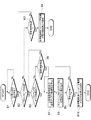
図2は、ディスクアレイ装置10及び自律電源制御ユニット11の構成を示すブロック図である。
FIG. 2 is a block diagram showing the configuration of the
ディスクアレイ装置10は、アレイコントローラ21及びディスクエンクロージャ31から構成されている。アレイコントローラ21の電力は、分電盤12から自律電源制御ユニット11及び電源を介して供給される。ディスクエンクロージャ31の電力は、分電盤12から電源を介して供給される。
The
アレイコントローラ21は、インタフェース22、他コントローラ通信部23、上位装置制御部24(ホスト制御部)、マイクロプロセッサ25(制御部)、不揮発性記録媒体26、メモリ27、キャッシュメモリ28、記録媒体29及び磁気ディスク制御部30(ディスク制御部)などにより構成されている。また、ディスクエンクロージャ31は、複数の磁気ディスク32により構成されている。
The
他のコントローラ通信部23は、ディスクアレイ装置10内に有しアレイコントローラ21と同様に構成されている他のアレイコントローラ(図示せず)と接続されており、当該他のアレイコントローラと通信することが可能である。
The other
マイクロプロセッサ25は、ホスト装置14からのI/Oコマンドに基づいて、ホスト装置14から送信されるデータをキャッシュメモリ28に格納し、その後、当該データを磁気ディスク32に格納する。また、マイクロプロセッサ25は、ホスト装置14からのI/Oコマンドに基づいて、磁気ディスク32から対応するデータを読み出してキャッシュメモリ28に格納し、その後、当該データをホスト装置14に送信する。
Based on the I / O command from the
自律電源制御ユニット11は、マイクロプロセッサ41(電源制御部)、畜電器42(第2の電源)及びメモリ43などにより構成されている。
The autonomous
自律電源制御ユニット11は、上述したようにSNMPマネージャ機能を実装しており、起動時に、SNMPマネージャ機能を有効にして、SNMPマネージャとして動作する。また、自律電源制御ユニット11は、初期設定時に、ホスト装置14、運用管理サーバ15、ネットワーク装置17などのSNMPエージェント群のネットワーク情報を設定し、管理テーブルを作成する。
As described above, the autonomous power
次に、分電盤12からAC(Alternating Current)電力が切断された場合の自律電源制御ユニット11の処理について、図3のフローチャートを参照して説明する。
Next, processing of the autonomous
マイクロプロセッサ41は、畜電器42が分電盤12から常に電力を供給されていることから、分電盤12のAC電力供給状態を蓄電器42との通信により、少なくともディスクアレイ装置10及び自律電源制御ユニット11へのAC電力の供給状態を監視している。
Since the
やがて、マイクロプロセッサ41は、前述の監視により、分電盤12からのAC電力の供給が切断されたと判断すると(ステップA1:YES)、ディスクアレイ装置10及び自己の装置である自律電源制御ユニット11に対して蓄電器42からの電力の供給を開始する(ステップA2)。
Eventually, if the
続いて、マイクロプロセッサ41は、管理対象であるホスト装置14、運用管理サーバ15、ネットワーク装置17などのSNMPエージェントから障害通知(SNMP Trap)を受信したか否かの判定を行う(ステップA3、A4)。
Subsequently, the
具体的に、マイクロプロセッサ41は、まず、ホスト装置14又は運用管理サーバ15から障害通知(SNMP Trap)を受信したか否かの判定を行う(ステップA3)。続いて、マイクロプロセッサ41は、ホスト装置14、運用管理サーバ15から障害通知を受信した場合(ステップA3:YES)、ネットワーク装置17からリンクダウン通知(障害通知)を受信したか否かの判定を行う(ステップA4)。
Specifically, the
このように、マイクロプロセッサ41は、アレイコントローラ21に対してAC電力切断通知を送信するか否かを判定するために、ネットワーク装置17からリンクダウン通知(障害通知)を受信したか否かの判定も同時に行う。例えば、ホスト装置14は、当該ホスト装置14単体で障害が発生した場合にも自律電源制御ユニット11に対して障害通知を行い、また、ネットワーク装置17を経由してホスト装置14がディスクアレイ装置10にアクセスしている場合、上位装置制御部24からではネットワークのリンク状態の変化を検出することができないからである。
As described above, the
続いて、マイクロプロセッサ41は、ネットワーク装置17からリンクダウン通知を受信した場合(ステップA4:YES)、ステップA6に進む。
Subsequently, when the
一方、マイクロプロセッサ41は、管理対象の全SNMPエージェントから障害通知を受信していない場合(ステップA2:NO)、又はネットワーク装置17からリンクダウン通知を受信していない場合(ステップA3:NO)、分電盤12からのAC電力の供給が切断されてから規定時間を経過したか否かを判定する(ステップA5)。
On the other hand, if the
つまり、障害通知の到達は、規定時間の待ちを考慮に入れて行う。この規定時間は、ディスクアレイ装置10の消費電力及び蓄電器42の容量、ディスクアレイ装置10のキャッシュメモリ28の容量及び又はキャッシュメモリ28から記録媒体29へのデータ転送速度などから算出する。マイクロプロセッサ41は、規定時間内は通知が受信することを待ち受け(ステップA5)、規定時間を経過した場合(ステップA5:YES)、ステップA6に進む。
That is, the arrival of the failure notification is performed taking into account the waiting for the specified time. This specified time is calculated from the power consumption of the
やがて、マイクロプロセッサ41は、インタフェース18を介して、アレイコントローラ21に対して、AC電力切断通知を送信する(ステップA6)。
Eventually, the
続いて、マイクロプロセッサ41は、アレイコントローラ21からの蓄電器42の電力停止通知が受信するのを待ち受ける(ステップA7)。やがて、マイクロプロセッサ41は、アレイコントローラ21からの蓄電器42の電力停止通知を受信すると(ステップA7:YES)、アレイコントローラに対して蓄電器42からの電力の供給を停止する(ステップA8)。
Subsequently, the
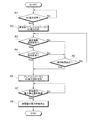
次に、AC電力切断通知を受信後のアレイコントローラ21の処理について、図4のフローチャートを参照して説明する。
Next, processing of the
マイクロプロセッサ25は、自律電源制御ユニット11からAC電力切断通知を受信すると(ステップB1:YES)、冗長コントローラ構成の場合、他系のコントローラである他のアレイコントローラ(図示せず)においてもAC電力切断通知を受信しているかの確認を他コントローラ通信部23を介して行う(ステップB2)。
When the
続いて、マイクロプロセッサ25は、他のアレイコントローラがAC電力切断通知を受信していない場合(ステップB2:NO)、分電盤12からのAC電力の供給が切断されてから上述の規定時間を経過するのを待ち受ける(ステップB3)。そして、マイクロプロセッサ25は、上述の規定時間を経過した場合(ステップB3:YES)、他のアレイコントローラが正常に動作していると判断し、蓄電器42の無駄な放電を防止するために、自系の自律電源制御ユニット11に対して畜電器42の電力停止通知を発行する(ステップB4)。
Subsequently, when the other array controller has not received the AC power disconnection notification (step B2: NO), the
なお、本実施形態の自律電源制御ユニット11は、マイクロプロセッサ25が上述の規定時間を経過した場合、AC電力切断通知を送信する(ステップA5、A6)。従って、他のアレイコントローラが自律電源制御ユニット11と同等の機能を持つ制御ユニットに接続されている場合、上述の規定時間を経過してもAC電力切断通知を受信しないならば(ステップB2、B3)、他のアレイコントローラの電源は切断されておらず、他のアレイコントローラが正常に動作していると判断できる。
Note that the autonomous
一方、マイクロプロセッサ25は、他のアレイコントローラもAC電力切断通知を受信した場合(ステップB2:YES)、自系のアレイコントローラ21の上位装置制御部24がホスト装置14からのI/Oコマンドを受信しており、当該I/Oコマンドがすべて処理されたか否かの確認を行う(ステップB5)。この判定時、ネットワーク装置17はリンクダウンしている場合、当該I/Oコマンドは、AC電力切断前に上位装置制御部24が受信した仕掛かり中のI/Oコマンドに相当する。
On the other hand, when the other array controller also receives the AC power disconnection notification (step B2: YES), the
そして、マイクロプロセッサ25は、自系のアレイコントローラ21の上位装置制御部24においてI/Oコマンドがすべて処理されていない場合(ステップB5:NO)、分電盤12からのAC電力の供給が切断されてから上述の規定時間を経過するのを待ち受ける(ステップB6)。そして、マイクロプロセッサ25は、規定時間を経過した場合(ステップB6:YES)、ステップB7に進む。
Then, when all the I / O commands are not processed in the host
一方、マイクロプロセッサ25は、自系のアレイコントローラ21の上位装置制御部24においてI/Oコマンドがすべて処理された場合にも(ステップB5:YES)、ステップB7に進む。
On the other hand, the
やがて、マイクロプロセッサ25は、蓄電器42からの放電を抑えるため、上位装置制御部24及び磁気ディスク制御部27の電源を切断し、当該上位装置制御部24及び磁気ディスク制御部27対する電力の供給も停止する(ステップB7)。
Eventually, the
続いて、マイクロプロセッサ25は、キャッシュメモリ28上のデータの記録媒体29への書き込みを開始する(ステップB8)。そして、マイクロプロセッサ25は、キャッシュメモリ28上のすべてのデータの記録媒体29への書き込みが完了すると(ステップB9:YES)、自系の自律電源制御ユニット11に畜電器42の電力停止通知を発行する(ステップB10)。
Subsequently, the
これにより、マイクロプロセッサ25は、蓄電器42の無駄な放電を抑えつつ、キャッシュメモリ28上のデータを迅速かつ安全に記録媒体29に退避することができる。マイクロプロセッサ25は、分電盤12からのAC電力の供給が復活し、次回立ち上げするときに、記録媒体29上のデータをキャッシュメモリ28に展開し、ホスト装置14の処理を再開することができる。
Thereby, the
このようにして、本実施形態のストレージシステム1では、自律電源制御ユニット11にSNMPマネージャ機能及び蓄電器42が実装され、ディスクアレイ装置10に記録媒体29が実装されている。また、ストレージシステム1では、ディスクアレイ装置10、自律電源制御ユニット11、ホスト装置14、運用管理サーバ15、ネットワーク装置17が運用管理用ネットワーク16に接続されている。そして、ストレージシステム1では、自律電源制御ユニット11がSNMPマネージャとして機能し、ホスト装置14、運用管理サーバ15、ネットワーク装置17がSNMPエージェントとして機能して、電源障害の発生、リンクダウンの発生時にSNMPエージェントがSNMPマネージャに障害を通知して、SNMPマネージャが、障害通知に基づいて電源制御を行う。
Thus, in the storage system 1 of the present embodiment, the SNMP manager function and the
従って、仕様の異なる複数のホスト装置がマルチプラットフォーム接続するディスクアレイ装置の電源制御を各社独自の電源制御仕様を意識せずに必要最低限の機器構成のみで行うことができる。 Therefore, power control of a disk array device in which a plurality of host devices having different specifications are connected to each other in a multi-platform can be performed with only the minimum necessary device configuration without being conscious of the power control specifications unique to each company.
そして、以上説明したように、本発明においては、以下に記載するような効果を奏する。第1の効果は、仕様の異なる複数のホスト装置14がマルチプラットフォーム接続するディスクアレイ装置10において、停電発生時などに、ホスト装置14からのI/Oコマンドを可能な限り処理した上で、書き込みレスポンスを向上するためのキャッシュメモリ29上のデータに退避することである。第2の効果は、専用ソフトウェアや専用機器を必要とせずに、安全な電源切断処理を行うことである。
And as demonstrated above, in this invention, there exists an effect as described below. The first effect is that, in the
なお、自律電源制御ユニット11が独立している理由は、アレイコントローラ21の小型化、ディスクアレイ装置10の設置環境に定電圧定周波数電源(CVCF(Constant Voltage Constant Frequency))が設置されており電源制御不要のニーズがあった際にも容易に対応できるようにするためである。
The autonomous power
(2)他実施形態のストレージシステム
なお、本実施形態のストレージシステム1では、自律電源制御ユニット11を独立して構成した場合について述べたが、本発明はこれに限らず、他実施形態のストレージシステム1として、例えば、自律電源制御ユニット11をディスクアレイ装置10に組み込んで構成するようにしても良い。この場合、ディスクアレイ装置10のマイクロプロセッサ25が、上述した分電盤12からAC電力が切断された場合の処理(図3)を行う。
(2) Storage System of Other Embodiments In the storage system 1 of the present embodiment, the case where the autonomous
すなわち、マイクロプロセッサ25は、分電盤12からの電力の供給が切断されたときに、畜電器42からの電力の供給を開始し、ホスト装置14及び又はネットワーク装置17から障害通知を受信した場合に、畜電器42から供給される電力によりキャッシュメモリ28に格納されているデータを記録媒体29に退避し、データの退避が終了した場合に、畜電器42からの電力の供給を停止する。
That is, when the power supply from the
これにより、自律電源制御ユニット11が不要になり、機器構成として、インタフェース18、電源ケーブル19、マイクロプロセッサ41及びメモリ43が不要となるため、必要となる機器数を削減することができるという効果がある。
This eliminates the need for the autonomous
また、他実施形態のストレージシステム1として、本発明をアプライアンスNAS(Network Attached Storage)装置に適用するようにしても良い。アプライアンスNAS装置では、図1のホスト装置14がNASゲートウェイ又はNASヘッドに置き換えられた構成となる。アプライアンスNAS装置では、ネットワーク装置17を介さず、ディスクアレイ装置10に直接アクセスする構成が多い。
Further, as the storage system 1 of another embodiment, the present invention may be applied to an appliance NAS (Network Attached Storage) device. The appliance NAS apparatus has a configuration in which the
この場合、ホスト装置のリンクダウンの検出は、アレイコントローラ21の上位装置制御部24が検出し、ディスクアレイ装置10及び自律電源制御ユニット11が独立して構成されている場合、運用管理用ネットワーク16を経由して、自律電源制御ユニット11に通知して自律電源制御ユニット11で処理し、自律電源制御ユニット11をディスクアレイ装置10に組み込んで構成されている場合、アレイコントローラ21内に閉じて全て処理することになる。なお、分電盤12からAC電力が切断された場合の処理(図3)及びAC電力切断通知を受信後のアレイコントローラ21の処理(図4)は、上述した場合と同様に行われる。
In this case, when the host device link down is detected by the host
さらに、他実施形態のストレージシステム1として、従来の独自の電源制御仕様による従来電源制御機構45を導入済みのシステムにストレージシステム1を導入するようにしても良い。
Further, as the storage system 1 of another embodiment, the storage system 1 may be introduced into a system in which the conventional
図5は、他実施形態のストレージシステム1の構成を示す図である。この場合、図5のストレージシステム1は、従来電源制御機構45が自律電源制御ユニット11のレガシーI/Fイン(LEGACY I/F IN)44に接続されていることを除いて、図2のストレージシステム1の構成と同様である。
FIG. 5 is a diagram illustrating a configuration of the storage system 1 according to another embodiment. In this case, the storage system 1 in FIG. 5 is similar to the storage system in FIG. 2 except that the conventional power
次に、従来電源制御機構45を導入済みのシステムにストレージシステム1を導入する際の電源制御方法について図6のフローチャートを参照して説明する。まず、自律電源制御ユニット11は、従来電源制御機構45が実装されているか否かを判断する(ステップC1)。続いて、自律電源制御ユニット11は、従来電源制御機構45が実装されている場合(ステップC1:YES)、SNMPマネージャ機能を無効化し(ステップC2)、従来電源制御機構45との通信を行うための制御タスクを起動する(ステップC3)。
Next, a power control method for introducing the storage system 1 into a system in which the conventional
続いて、自律電源制御ユニット11は、従来電源制御機構45からコマンドを受信したか否かを判定し(ステップC4)、コマンドを受信した場合(ステップC4:YES)、当該コマンドの内容の解析を行い(ステップC5)、アレイコントローラ21に解析結果に基づいた電源制御情報を送信する(ステップC6)。
Subsequently, the autonomous power
例えば、自律電源制御ユニット11は、従来電源制御機構45からコマンドが分電盤12からの電力が切断された旨のAC電力切断コマンドである場合、当該AC電力切断通知に対応する電源制御情報をアレイコントローラ21に送信する。
For example, when the command from the conventional
これにより、自律電源制御ユニット11は、従来の独自の電源制御仕様で稼動しているシステムにおいても、電源制御を行うことができる。このように、ストレージシステム1では、自律電源制御ユニット11に従来からの電源制御仕様の機構と接続するためのレガシーI/Fインが実装されており、自律電源制御ユニット11が仕様開示されている独自機構のコマンドを解釈して電源制御を行うこともできる。
As a result, the autonomous
本発明は、本実施の形態のディスクアレイ装置10に限らず、データストレージ専用ネットワーク(FC−SAN、IP−SAN)におけるホスト・SANスイッチ・ディスクアレイ装置、ファイルサーバ専用のNAS装置、ホスト装置に接続される周辺装置全般の電源制御において利用可能である。
The present invention is not limited to the
1……ストレージシステム、10……ディスクアレイ装置、11……自律電源制御ユニット、12……分電盤(AC供給源)、13……ACケーブル、14……ホスト装置、15……運用管理サーバ、16……運用管理用ネットワーク、17……ストレージネットワーク、18……インタフェース、19……ACケーブル、21……アレイコントローラ、22……インタフェース、23……他コントローラ通信部、24……上位装置制御部、25……マイクロプロセッサ、26……不揮発性記録媒体、27……メモリ、28……キャッシュメモリ、29……記録媒体、30……磁気ディスク制御部、31……ディスクエンクロージャ、32……磁気ディスク、41……マイクロプロセッサ、42……蓄電器、43……メモリ、44……レガシーI/Fイン、45……従来電源制御機構
DESCRIPTION OF SYMBOLS 1 ... Storage system, 10 ... Disk array apparatus, 11 ... Autonomous power supply control unit, 12 ... Distribution board (AC supply source), 13 ... AC cable, 14 ... Host device, 15 ... Operation management Server, 16 ... Operation management network, 17 ... Storage network, 18 ... Interface, 19 ... AC cable, 21 ... Array controller, 22 ... Interface, 23 ... Other controller communication unit, 24 ... Upper level
Claims (7)
前記第1の電源からの電力の供給が切断されたときに、前記ディスクアレイ装置及び前記自装置に電力を供給するための第2の電源と
を備え、
前記電源制御部は、
SNMP(Simple Network Management Protocol)に基づき、前記複数のホスト装置及び前記ネットワーク装置の電源障害情報を収集する手段と、
前記第1の電源からの電力の供給が切断されたときに、前記ディスクアレイ装置及び前記自装置に対して第2の電源からの電力の供給を開始する手段と、
前記第2の電源からの電力供給の開始後に、前記SNMPによって前記電源障害情報が収集された場合に、前記第1の電源からの電力の供給が切断された旨の電力切断通知を前記ディスクアレイ装置に送信する手段と
を備えることを特徴とする電源制御装置。 A power supply control unit that controls power supplied from a first power supply to a disk array device and its own device that are accessible from a plurality of host devices having different specifications via a network device;
A second power source for supplying power to the disk array device and the device when power supply from the first power source is cut off, and
The power control unit
Based on SNMP (Simple Network Management Protocol), means for collecting power failure information of the plurality of host devices and the network device;
Means for starting the supply of power from a second power source to the disk array device and the host device when the supply of power from the first power source is cut off;
If the power failure information is collected by the SNMP after the start of power supply from the second power supply, a power cut notification indicating that power supply from the first power supply has been cut off is sent to the disk array. A power control apparatus comprising: means for transmitting to the apparatus.
前記複数のホスト装置及び前記ネットワーク装置から前記電源障害情報を受信していない場合に、前記ディスクアレイ装置の消費電力、前記第2の電源の容量、前記ディスクアレイ装置のキャッシュメモリの容量及び前記キャッシュメモリのデータを所定領域に退避するための転送速度に基づいて算出される所定の時間を経過したときに、前記電力切断通知を前記ディスクアレイ装置に送信する
ことを特徴とする請求項1に記載の電源制御装置。 The power control unit
When the power failure information is not received from the plurality of host devices and the network device, the power consumption of the disk array device, the capacity of the second power supply, the capacity of the cache memory of the disk array device, and the cache 2. The power-off notification is transmitted to the disk array device when a predetermined time calculated based on a transfer rate for saving data in a memory to a predetermined area has elapsed. Power supply control device.
前記ディスクアレイ装置とを含み、
前記ディスクアレイ装置は、
前記複数のホスト装置とのI/Oコマンドの送受信を制御するホスト制御部と、
前記データを格納するディスクとの前記データの送受信を制御するディスク制御部と、
前記複数のホスト装置から送信されるI/Oコマンドに基づく前記データを一時的に格納するキャッシュメモリと、
前記複数のホスト制御部、前記前記ディスク制御部及び前記キャッシュメモリを制御し、前記ホスト装置との前記データの送受信を制御する制御部とを含み、
前記制御部は、
前記電力切断通知を受信した場合に、前記ホスト制御部が前記I/Oコマンドを保持している場合には、当該I/Oコマンドの処理を実行する手段と、
前記ホスト制御部が保持しているすべての前記I/Oコマンドの処理が終了した場合に、前記ホスト制御部及び前記ディスク制御部に対して前記第2の電源からの電力の供給を停止する手段と、
前記ホスト制御部及び前記ディスク制御部に対する前記第2の電源からの電力の供給を停止した後に、前記キャッシュメモリに格納されている前記データを前記ディスクアレイ装置の有する所定の記録媒体に退避する手段と、
前記データの退避が終了した場合に、前記電力供給停止通知を前記電源制御装置に送信する手段と
を備えることを特徴とするストレージシステム。 The power supply control device according to claim 1 or 2,
Including the disk array device,
The disk array device
A host control unit for controlling transmission / reception of I / O commands with the plurality of host devices;
A disk control unit that controls transmission and reception of the data with a disk that stores the data;
A cache memory for temporarily storing the data based on an I / O command transmitted from the plurality of host devices;
A control unit that controls the plurality of host control units, the disk control unit, and the cache memory, and controls transmission and reception of the data with the host device;
The controller is
Means for executing processing of the I / O command when the host control unit holds the I / O command when the power disconnection notification is received;
Means for stopping supply of power from the second power source to the host control unit and the disk control unit when processing of all the I / O commands held by the host control unit is completed When,
Means for saving the data stored in the cache memory to a predetermined recording medium of the disk array device after stopping the supply of power from the second power source to the host control unit and the disk control unit When,
A storage system comprising: means for transmitting the power supply stop notification to the power supply control device when the saving of the data is completed.
前記ホスト制御部、前記ディスク制御部、前記キャッシュメモリ及び前記制御部を含む第1のコントローラと同様に構成されている冗長構成の第2のコントローラを含み、
前記制御部は、
前記第2のコントローラが前記電力供給停止通知を受信したか否かをチェックし、前記第2のコントローラが前記電力供給停止通知を前記所定の時間受信しなかった場合に、前記第2の電源からの電力の供給を停止する旨の電力供給停止通知を前記電源制御装置に送信する
ことを特徴とする請求項3に記載のストレージシステム。 The disk array device
A redundant controller configured in the same manner as the first controller including the host controller, the disk controller, the cache memory, and the controller;
The controller is
It is checked whether the second controller has received the power supply stop notification, and if the second controller has not received the power supply stop notification for the predetermined time, the second power supply The storage system according to claim 3, wherein a power supply stop notification to stop the supply of power is transmitted to the power supply control device.
前記第1の電源からの電力の供給が切断されたときに、前記ディスクアレイ装置及び前記自装置に電力を供給するための第2の電源と
を備え、
前記電源制御部は、
前記複数のホスト装置及び前記ネットワーク装置の電源の管理を行う独自の機能を有する機構に基づき、前記複数のホスト装置及び前記ネットワーク装置の電源障害情報を収集する手段と、
前記第1の電源からの電力の供給が切断されたときに、前記ディスクアレイ装置及び前記自装置に対して第2の電源からの電力の供給を開始する手段と、
前記第2の電源からの電力供給の開始後に、前記独自の機能を有する機構によって前記電源障害情報が収集された場合に、前記第1の電源からの電力の供給が切断された旨の電力切断通知を前記ディスクアレイ装置に送信する手段と
を備えることを特徴とする電源制御装置。 A power supply control unit that controls power supplied from a first power supply to a disk array device and its own device that are accessible from a plurality of host devices having different specifications via a network device;
A second power source for supplying power to the disk array device and the device when power supply from the first power source is cut off, and
The power control unit
Means for collecting power failure information of the plurality of host devices and the network device based on a mechanism having a unique function of managing power of the plurality of host devices and the network device;
Means for starting the supply of power from a second power source to the disk array device and the host device when the supply of power from the first power source is cut off;
When the power failure information is collected by the mechanism having the unique function after the power supply from the second power supply is started, the power cut to the effect that the power supply from the first power supply is cut off Means for transmitting a notification to the disk array device.
SNMP(Simple Network Management Protocol)に基づき、前記複数のホスト装置及び前記ネットワーク装置の電源障害情報を収集するステップと、
前記第1の電源からの電力の供給が切断されたときに、前記ディスクアレイ装置及び前記自装置に対して第2の電源からの電力の供給を開始するステップと、
前記第2の電源からの電力供給の開始後に、前記SNMPによって前記電源障害情報が収集された場合に、前記第1の電源からの電力の供給が切断された旨の電力切断通知を前記ディスクアレイ装置に送信するステップと
を備えることを特徴とする電源制御装置の制御方法。 A power supply control unit that controls power supplied from a first power supply to a disk array device and its own device that are accessible from a plurality of host devices having different specifications via a network device; And a second power supply for supplying power to the disk array device and the device when the supply of power is cut off.
Collecting power failure information of the plurality of host devices and the network device based on SNMP (Simple Network Management Protocol);
Starting the supply of power from a second power source to the disk array device and the device when the supply of power from the first power source is cut off;
If the power failure information is collected by the SNMP after the start of power supply from the second power supply, a power cut notification indicating that power supply from the first power supply has been cut off is sent to the disk array. And a step of transmitting to the apparatus.
前記複数のホスト装置とのI/Oコマンドの送受信を制御するホスト制御部と、
前記データを格納するディスクとの前記データの送受信を制御するディスク制御部と、
前記複数のホスト装置から送信されるI/Oコマンドに基づく前記データを一時的に格納するキャッシュメモリと、
前記複数のホスト制御部、前記前記ディスク制御部及び前記キャッシュメモリを制御し、前記ホスト装置との前記データの送受信を制御すると共に、第1の電源から自装置に対して供給される電力の制御を行う制御部と、
前記第1の電源からの電力の供給が切断されたときに、前記ディスクアレイ装置及び前記自装置に電力を供給するための第2の電源とを含み、
前記制御部は、
SNMP(Simple Network Management Protocol)に基づき、前記複数のホスト装置及び前記ネットワーク装置の電源障害情報を収集する手段と、
前記第1の電源からの電力の供給が切断されたときに、前記第2の電源からの電力の供給を開始する手段と、
前記第2の電源からの電力供給の開始後に、前記SNMPによって前記電源障害情報が収集された場合に、前記ホスト制御部が前記I/Oコマンドを保持している場合には、当該I/Oコマンドの処理を実行する手段と、
前記ホスト制御部が保持しているすべての前記I/Oコマンドの処理が終了した場合に、前記ホスト制御部及び前記ディスク制御部に対して前記第2の電源からの電力の供給を停止する手段と、
前記ホスト制御部及び前記ディスク制御部に対する前記第2の電源からの電力の供給を停止した後に、前記キャッシュメモリに格納されている前記データを前記ディスクアレイ装置の有する所定の記録媒体に退避する手段と
を備えることを特徴とするディスクアレイ装置。 A disk array device connected via a network device from a plurality of host devices having different specifications,
A host control unit for controlling transmission / reception of I / O commands with the plurality of host devices;
A disk control unit that controls transmission and reception of the data with a disk that stores the data;
A cache memory for temporarily storing the data based on an I / O command transmitted from the plurality of host devices;
Controls the plurality of host control units, the disk control unit, and the cache memory, controls transmission / reception of the data to / from the host device, and controls power supplied from the first power source to the own device A control unit for performing
A second power source for supplying power to the disk array device and the device when power supply from the first power source is cut off,
The controller is
Based on SNMP (Simple Network Management Protocol), means for collecting power failure information of the plurality of host devices and the network device;
Means for starting the supply of power from the second power supply when the supply of power from the first power supply is cut off;
If the host control unit holds the I / O command when the power failure information is collected by the SNMP after the start of power supply from the second power source, the I / O Means for executing command processing;
Means for stopping supply of power from the second power source to the host control unit and the disk control unit when processing of all the I / O commands held by the host control unit is completed When,
Means for saving the data stored in the cache memory to a predetermined recording medium of the disk array device after stopping the supply of power from the second power source to the host control unit and the disk control unit A disk array device comprising:
Priority Applications (2)
| Application Number | Priority Date | Filing Date | Title |
|---|---|---|---|
| JP2009216119A JP5729746B2 (en) | 2009-09-17 | 2009-09-17 | Storage system and disk array device |
| US12/885,262 US8347139B2 (en) | 2009-09-17 | 2010-09-17 | Power supply control device, a storage system, a control method of the power supply control device, a control method of a disk array unit and a computer readable medium thereof |
Applications Claiming Priority (1)
| Application Number | Priority Date | Filing Date | Title |
|---|---|---|---|
| JP2009216119A JP5729746B2 (en) | 2009-09-17 | 2009-09-17 | Storage system and disk array device |
Publications (2)
| Publication Number | Publication Date |
|---|---|
| JP2011065480A true JP2011065480A (en) | 2011-03-31 |
| JP5729746B2 JP5729746B2 (en) | 2015-06-03 |
Family
ID=43731643
Family Applications (1)
| Application Number | Title | Priority Date | Filing Date |
|---|---|---|---|
| JP2009216119A Active JP5729746B2 (en) | 2009-09-17 | 2009-09-17 | Storage system and disk array device |
Country Status (2)
| Country | Link |
|---|---|
| US (1) | US8347139B2 (en) |
| JP (1) | JP5729746B2 (en) |
Cited By (2)
| Publication number | Priority date | Publication date | Assignee | Title |
|---|---|---|---|---|
| JP2016118954A (en) * | 2014-12-22 | 2016-06-30 | 富士通株式会社 | Information processor, processing method, and program |
| JP2023044516A (en) * | 2021-09-17 | 2023-03-30 | 横河電機株式会社 | Terminal device |
Families Citing this family (7)
| Publication number | Priority date | Publication date | Assignee | Title |
|---|---|---|---|---|
| JP5397609B2 (en) * | 2009-09-01 | 2014-01-22 | 日本電気株式会社 | Disk array device |
| WO2012147083A1 (en) | 2011-04-25 | 2012-11-01 | Generic Imaging Ltd. | System and method for correction of vignetting effect in multi-camera flat panel x-ray detectors |
| US20140108705A1 (en) * | 2012-10-12 | 2014-04-17 | Sandisk Technologies Inc. | Use of High Endurance Non-Volatile Memory for Read Acceleration |
| US9465426B2 (en) * | 2013-09-18 | 2016-10-11 | Huawei Technologies Co., Ltd. | Method for backing up data in a case of power failure of storage system, and storage system controller |
| CN106033244A (en) * | 2015-03-20 | 2016-10-19 | 技嘉科技股份有限公司 | Motherboard with stand-by power supply |
| US10353768B2 (en) * | 2015-06-29 | 2019-07-16 | Hitachi, Ltd. | Computer system and computer system control method |
| CN115065628B (en) * | 2022-05-30 | 2024-02-13 | 一汽奔腾轿车有限公司 | Automatic test method and test system for fault code self-clearing of controller without sleep strategy |
Citations (9)
| Publication number | Priority date | Publication date | Assignee | Title |
|---|---|---|---|---|
| JPH11143649A (en) * | 1997-11-04 | 1999-05-28 | Fujitsu Ltd | Disk array device |
| JPH11305879A (en) * | 1998-04-20 | 1999-11-05 | Hitachi Ltd | Link control system among host, disk array and ups |
| JP2000163164A (en) * | 1998-11-24 | 2000-06-16 | Isa:Kk | Power source controller and no-break power unit |
| JP2000357059A (en) * | 1999-06-14 | 2000-12-26 | Toshiba Corp | Disk array device |
| JP2003036125A (en) * | 2001-07-24 | 2003-02-07 | Yuasa Corp | Power failure power unit for disk array device, disk array system and disk array device, or starting and stopping method for disk array system |
| JP2004133897A (en) * | 2002-09-06 | 2004-04-30 | Hitachi Ltd | Event notification in storage network |
| JP2005301442A (en) * | 2004-04-07 | 2005-10-27 | Hitachi Ltd | Storage device |
| JP2006072545A (en) * | 2004-08-31 | 2006-03-16 | Fujitsu Ltd | Power supply control method, power supply control device, and information processor |
| JP2008203957A (en) * | 2007-02-16 | 2008-09-04 | Nec Corp | Nas system |
Family Cites Families (7)
| Publication number | Priority date | Publication date | Assignee | Title |
|---|---|---|---|---|
| USRE40866E1 (en) * | 2000-09-27 | 2009-08-04 | Huron Ip Llc | System, method, and architecture for dynamic server power management and dynamic workload management for multiserver environment |
| JP3771162B2 (en) * | 2001-10-03 | 2006-04-26 | 株式会社日立製作所 | Maintenance management method, maintenance management system, information processing system, and computer program |
| JP3900467B2 (en) | 2001-11-05 | 2007-04-04 | インターナショナル・ビジネス・マシーンズ・コーポレーション | EXTERNAL STORAGE DEVICE, EXTERNAL STORAGE DEVICE CONTROL METHOD, PROGRAM, AND RECORDING MEDIUM |
| US7406623B2 (en) * | 2003-09-29 | 2008-07-29 | Hitachi Computer Peripherals Co., Ltd. | DC backup power supply system and disk array using same |
| JP2005149436A (en) * | 2003-11-20 | 2005-06-09 | Hitachi Ltd | Storage apparatus, control method for storage apparatus, job scheduling processing method, troubleshooting method and their program |
| JP2005301476A (en) * | 2004-04-08 | 2005-10-27 | Hitachi Ltd | Power supply control system and storage device |
| JP2005346321A (en) * | 2004-06-02 | 2005-12-15 | Hitachi Ltd | Disk array apparatus and method for controlling battery output of disk array apparatus |
-
2009
- 2009-09-17 JP JP2009216119A patent/JP5729746B2/en active Active
-
2010
- 2010-09-17 US US12/885,262 patent/US8347139B2/en active Active
Patent Citations (9)
| Publication number | Priority date | Publication date | Assignee | Title |
|---|---|---|---|---|
| JPH11143649A (en) * | 1997-11-04 | 1999-05-28 | Fujitsu Ltd | Disk array device |
| JPH11305879A (en) * | 1998-04-20 | 1999-11-05 | Hitachi Ltd | Link control system among host, disk array and ups |
| JP2000163164A (en) * | 1998-11-24 | 2000-06-16 | Isa:Kk | Power source controller and no-break power unit |
| JP2000357059A (en) * | 1999-06-14 | 2000-12-26 | Toshiba Corp | Disk array device |
| JP2003036125A (en) * | 2001-07-24 | 2003-02-07 | Yuasa Corp | Power failure power unit for disk array device, disk array system and disk array device, or starting and stopping method for disk array system |
| JP2004133897A (en) * | 2002-09-06 | 2004-04-30 | Hitachi Ltd | Event notification in storage network |
| JP2005301442A (en) * | 2004-04-07 | 2005-10-27 | Hitachi Ltd | Storage device |
| JP2006072545A (en) * | 2004-08-31 | 2006-03-16 | Fujitsu Ltd | Power supply control method, power supply control device, and information processor |
| JP2008203957A (en) * | 2007-02-16 | 2008-09-04 | Nec Corp | Nas system |
Cited By (4)
| Publication number | Priority date | Publication date | Assignee | Title |
|---|---|---|---|---|
| JP2016118954A (en) * | 2014-12-22 | 2016-06-30 | 富士通株式会社 | Information processor, processing method, and program |
| US10210057B2 (en) | 2014-12-22 | 2019-02-19 | Fujitsu Limited | Information processing apparatus with memory backup function for power failure |
| JP2023044516A (en) * | 2021-09-17 | 2023-03-30 | 横河電機株式会社 | Terminal device |
| US11956004B2 (en) | 2021-09-17 | 2024-04-09 | Yokogawa Electric Corporation | Terminal apparatus |
Also Published As
| Publication number | Publication date |
|---|---|
| JP5729746B2 (en) | 2015-06-03 |
| US20110066884A1 (en) | 2011-03-17 |
| US8347139B2 (en) | 2013-01-01 |
Similar Documents
| Publication | Publication Date | Title |
|---|---|---|
| JP5729746B2 (en) | Storage system and disk array device | |
| JP4838112B2 (en) | Power consumption adjustment program, apparatus, and processing method | |
| US8176208B2 (en) | Storage system and operating method of storage system | |
| US20100228960A1 (en) | Virtual memory over baseboard management controller | |
| JP6130520B2 (en) | MULTISYSTEM SYSTEM AND MULTISYSTEM SYSTEM MANAGEMENT METHOD | |
| JP2006107080A (en) | Storage device system | |
| US20100057991A1 (en) | Method for controlling storage system, storage system, and storage apparatus | |
| JP2005192306A (en) | Uninterruptible power supply device, power supply control program, recording medium for power supply control program, and power supply control method | |
| JP2008203957A (en) | Nas system | |
| CN103984616A (en) | Server monitoring method and server | |
| JP2012128573A (en) | Duplex system and building management system using the same | |
| JP2008225567A (en) | Information processing system | |
| JP2019091152A (en) | Storage system with power-saving function | |
| CN111506332B (en) | Remote-controlled data storage device and remote control system | |
| WO2019043815A1 (en) | Storage system | |
| JP2003115896A (en) | Method and system for maintenance, and information processing system | |
| CN114138567A (en) | Substrate management control module maintenance method, device, equipment and storage medium | |
| JP5884365B2 (en) | Power supply and program | |
| JP2004151824A (en) | Network system | |
| JP2011081465A (en) | Power source controller | |
| JP4098004B2 (en) | Power interlock control method | |
| JP4966610B2 (en) | Information processing system, emergency power-off method for information processing system | |
| JP4987450B2 (en) | Image forming apparatus | |
| JP4739432B2 (en) | Redundant system, control device, and control method | |
| EP2083537B1 (en) | Data network and method of controlling thereof |
Legal Events
| Date | Code | Title | Description |
|---|---|---|---|
| A621 | Written request for application examination |
Free format text: JAPANESE INTERMEDIATE CODE: A621 Effective date: 20120813 |
|
| A977 | Report on retrieval |
Free format text: JAPANESE INTERMEDIATE CODE: A971007 Effective date: 20130621 |
|
| A131 | Notification of reasons for refusal |
Free format text: JAPANESE INTERMEDIATE CODE: A131 Effective date: 20130709 |
|
| A521 | Written amendment |
Free format text: JAPANESE INTERMEDIATE CODE: A523 Effective date: 20130906 |
|
| A02 | Decision of refusal |
Free format text: JAPANESE INTERMEDIATE CODE: A02 Effective date: 20131216 |
|
| A61 | First payment of annual fees (during grant procedure) |
Free format text: JAPANESE INTERMEDIATE CODE: A61 Effective date: 20150402 |
|
| R150 | Certificate of patent or registration of utility model |
Ref document number: 5729746 Country of ref document: JP Free format text: JAPANESE INTERMEDIATE CODE: R150 |