JP2011064449A - Water tank including airtightness holding part - Google Patents
Water tank including airtightness holding part Download PDFInfo
- Publication number
- JP2011064449A JP2011064449A JP2010185800A JP2010185800A JP2011064449A JP 2011064449 A JP2011064449 A JP 2011064449A JP 2010185800 A JP2010185800 A JP 2010185800A JP 2010185800 A JP2010185800 A JP 2010185800A JP 2011064449 A JP2011064449 A JP 2011064449A
- Authority
- JP
- Japan
- Prior art keywords
- edge
- inner cylinder
- cover
- cylinder
- outer cylinder
- Prior art date
- Legal status (The legal status is an assumption and is not a legal conclusion. Google has not performed a legal analysis and makes no representation as to the accuracy of the status listed.)
- Pending
Links
Images


Classifications
-
- F—MECHANICAL ENGINEERING; LIGHTING; HEATING; WEAPONS; BLASTING
- F24—HEATING; RANGES; VENTILATING
- F24H—FLUID HEATERS, e.g. WATER OR AIR HEATERS, HAVING HEAT-GENERATING MEANS, e.g. HEAT PUMPS, IN GENERAL
- F24H1/00—Water heaters, e.g. boilers, continuous-flow heaters or water-storage heaters
- F24H1/18—Water-storage heaters
- F24H1/20—Water-storage heaters with immersed heating elements, e.g. electric elements or furnace tubes
- F24H1/208—Water-storage heaters with immersed heating elements, e.g. electric elements or furnace tubes with tubes filled with heat transfer fluid
-
- F—MECHANICAL ENGINEERING; LIGHTING; HEATING; WEAPONS; BLASTING
- F24—HEATING; RANGES; VENTILATING
- F24H—FLUID HEATERS, e.g. WATER OR AIR HEATERS, HAVING HEAT-GENERATING MEANS, e.g. HEAT PUMPS, IN GENERAL
- F24H1/00—Water heaters, e.g. boilers, continuous-flow heaters or water-storage heaters
- F24H1/18—Water-storage heaters
- F24H1/181—Construction of the tank
Abstract
Description
本発明は、気密保持部が備えられた水槽に関するものであって、詳細には水槽の組立てが容易に行われ、気密保持力を様々な実施例により向上させると共に、水槽内の洗浄が可能となるようにする、気密保持部が備えられた水槽に関する。 The present invention relates to a water tank provided with an airtight holding portion, and in particular, the water tank can be easily assembled, the airtight holding power can be improved by various embodiments, and the water tank can be cleaned. It is related with the water tank provided with the airtight holding | maintenance part.
冷温水器、浄水器、自動販売機などのように外部より供給される水を加熱又は冷却し、希望の温度の水や飲料に飲めるようにする装置には、通常、水槽をその内部に備えており、前記した水槽は、耐熱性、耐腐食性、耐衝撃性、耐久性及び成形の都合上、通常、ステンレススチール又はアルミニウムなどの金属材からなる。 A device that heats or cools water supplied from the outside, such as a chiller / heater, water purifier, vending machine, etc., so that it can be drunk into water or beverage at a desired temperature is usually equipped with a water tank. The above-described water tank is usually made of a metal material such as stainless steel or aluminum for heat resistance, corrosion resistance, impact resistance, durability and molding convenience.
このような水槽は、一般に、胴体部とカバーとからなり、胴体部とカバー相互間の気密保持のために溶接を行うことがあるが、胴体部とカバーとの間の溶接部位に沿って生じえる脆性に起因して亀裂や漏水が発生する虞があり、長時間使用すると、該当部位の腐食により人体に有害な物質が発生することもあ る。そして、前記水槽を長時間使用時、内部に微細物が繁殖したり、水垢のような異物が生じたりすることがあるので、水槽の内部を洗浄する必要がある。 Such a water tank is generally composed of a body part and a cover, and may be welded to maintain airtightness between the body part and the cover, but occurs along the welded part between the body part and the cover. There is a risk that cracks and water leakage may occur due to brittleness, and if used for a long time, harmful substances may be generated in the human body due to corrosion of the corresponding part. Further, when the water tank is used for a long time, fines may propagate inside or foreign substances such as scale may be generated, so it is necessary to clean the inside of the water tank.
そして、前記水槽は、金属材からなることが多く、高い熱伝導率による外部への熱放出が容易に行われるため、水槽内の水を希望の温度に加熱又は冷却させても、水槽内の水温が直ぐ常温になるので、引き続いて水槽内の水を加熱又は冷却するためのエネルギーの消耗を避けることはできなかった。 And since the water tank is often made of a metal material and heat release to the outside with high thermal conductivity is easily performed, even if the water in the water tank is heated or cooled to a desired temperature, Since the water temperature immediately became room temperature, it was not possible to avoid exhaustion of energy for subsequently heating or cooling the water in the water tank.
また、前記水槽は、熱損失を最少化するために外側に別途設けられた難燃性又は不燃性の断熱材で覆うといった手間を取るような作業が伴うと共に、断熱材の効果が期待に添えないという欠点もあった。 In addition, the water tank is accompanied by work that takes time and effort, such as covering it with a flame-retardant or non-flammable heat insulating material separately provided on the outside in order to minimize heat loss, and the effect of the heat insulating material is expected. There was also the disadvantage of not.
前記した問題点などを改善するために案出された本発明は、確実な気密保持を確保できるようにする、気密保持部が備えられた水槽を提供することにその目的がある。 The present invention devised to improve the above-described problems and the like has an object to provide a water tank provided with an airtight holding portion that ensures secure airtight holding.
また、本発明は、水槽内の洗浄が容易であると共に、気密の保持が確実に行われるようにする、気密保持部が備えられた水槽を提供することにその他の目的がある。 Another object of the present invention is to provide a water tank provided with an airtight holding portion that facilitates cleaning of the water tank and ensures that airtightness is maintained.
さらに、本発明は、断熱性能を高くし、水槽内の水を加熱又は冷却させるためのエネルギー消耗量を最少化できるようにする、気密保持部が備えられた水槽を提供することに他の目的がある。 Furthermore, the present invention has another object to provide a water tank provided with an airtight holding part that enhances heat insulation performance and minimizes energy consumption for heating or cooling water in the water tank. There is.
前記目的を達成するために、本発明による気密保持部が備えられた水槽は、一側が開放され、水が収容される胴体部と、前記胴体部を仕上げると共に、外部から供給される熱源により前記胴体部に収容された水を加熱又は冷却させる温度制御具が取り付けられるカバーと、前記胴体部と前記カバーを相互組み合わせ、気密を保持する気密保持部とを含む構造を有する。 In order to achieve the above-mentioned object, a water tank equipped with an airtight holding part according to the present invention has a body part that is open on one side, accommodates water, finishes the body part, and is heated by an externally supplied heat source. It has a structure including a cover to which a temperature control tool for heating or cooling water contained in the body part is attached, and an airtight holding part for keeping the body part and the cover in combination and maintaining airtightness.
望ましい実施例によれば、前記気密保持部は、円筒形状からなる前記胴体部の開放側縁部に沿って形成された拡管部の内壁に挿入され、前記内壁に並置された谷部を形成するように前記カバーの縁部に沿って形成される第1の折曲部と、前記第1の折曲部から延びて前記拡管部とカーリング加工により結合され、前記胴体部の外壁に沿って圧着される第2の折曲部とを含む構造を適用できる。 According to a preferred embodiment, the hermetic holding portion is inserted into an inner wall of an expanded tube portion formed along an open side edge portion of the trunk portion having a cylindrical shape, and forms a valley portion juxtaposed to the inner wall. The first bent portion formed along the edge of the cover, and extended from the first bent portion, coupled with the tube expansion portion by curling, and crimped along the outer wall of the body portion A structure including the second bent portion to be applied can be applied.
望ましい実施例によれば、前記胴体部は、水が収容される内筒と、前記内筒の外面との間に空間部を形成しながら、前記内筒を取り囲む外筒とを含み、前記カバーは、前記内筒及び外筒を仕上げると共に、前記気密保持部は、前記内筒と前記カバーの間、又は前記外筒と前記カバーの間に取り付けられ、前記内筒及び外筒の密封状態を維持し、前記外筒は、前記内筒の開放された一側の縁部と一体に結合され、前記外筒の内面と前記内筒の外面との間は真空状態に維持する構造を適用できる。 According to a preferred embodiment, the body portion includes an inner cylinder that stores water, and an outer cylinder that surrounds the inner cylinder while forming a space between the outer surface of the inner cylinder and the cover. Finishes the inner cylinder and the outer cylinder, and the airtight holding portion is attached between the inner cylinder and the cover or between the outer cylinder and the cover, and the sealed state of the inner cylinder and the outer cylinder The outer cylinder is integrally coupled with an open edge of the inner cylinder, and a structure can be applied in which a vacuum state is maintained between the inner surface of the outer cylinder and the outer surface of the inner cylinder. .
本発明による、気密保持部が備えられた水槽は、次のような利点を有する。先ず、カバーと胴体部との間が、加工過程においてぐらつきなく堅固に固定された状態でカーリング加工を行うので、気密保持力を向上できる。 The water tank provided with the airtight holding part according to the present invention has the following advantages. First, since the curling process is performed in a state in which the cover and the body portion are firmly fixed without wobbling in the processing process, the hermetic holding force can be improved.
また、胴体部が、真空の空間部を有する内筒と外筒の二重構造からなっているので、断熱性が向上し、水を加熱又は冷却するための電力消耗を減らすことができる。 Moreover, since the trunk | drum consists of the double structure of the inner cylinder and outer cylinder which have a vacuum space part, heat insulation improves and it can reduce the power consumption for heating or cooling water.
また、カバーと胴体部が相互着脱分離可能な気密保持部の構造を採用していることによって、水槽の洗浄が容易に行われる。 Further, the water tank can be easily cleaned by adopting a structure of an airtight holding part in which the cover and the body part are detachable from each other.
さらに、内筒と外筒の間に真空の空間部が設けられた構造を採用していることによって、別途の断熱材を付け加えることがないので、断熱性能を向上させることはもちろん、原価コストの削減を図れる。 In addition, by adopting a structure in which a vacuum space is provided between the inner cylinder and the outer cylinder, there is no need to add a separate heat insulating material. Reduction can be achieved.
以下、添付図面を参照し、本発明の望ましい実施例について説明する。 Hereinafter, preferred embodiments of the present invention will be described with reference to the accompanying drawings.
これは、本発明が属する技術分野において通常の知識を有する者が発明を容易に実施し得る程度に詳細に説明するためのものであって、これに本発明の技術的思想及び範疇が限定されることを意味するのではない。 This is for the purpose of explaining in detail to such an extent that a person having ordinary knowledge in the technical field to which the present invention belongs can easily carry out the invention, and this limits the technical idea and category of the present invention. It does not mean that.
なお、図面に示している構成要素のサイズや形状などは、説明の明瞭性と利便性を図るために誇張して図示することができ、本発明の構成及び作用を考慮のうえ、特別に正義された用語等は、使用者や運用者の意図または慣例によって異なり、このような用語等に対する正義は、この明細書全般の内容に基づいて下されるべきである。 It should be noted that the size and shape of the components shown in the drawings can be exaggerated for the sake of clarity and convenience of description, and special justice is taken into account in view of the configuration and operation of the present invention. The terminology used depends on the intention or practice of the user or operator, and the justice for such terminology should be based on the contents of this specification as a whole.
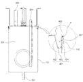
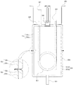
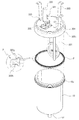
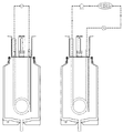
図1は、本発明の一実施例による、気密保持部が備えられた水槽の全体的な構造を示す斜視図であり、図2は、本発明の他の実施例による気密保持部が備えられた水槽の全体的な構造を示す斜視図であり、図3は、図2の断部概念図である。 FIG. 1 is a perspective view illustrating an overall structure of a water tank provided with an airtight holding unit according to an embodiment of the present invention, and FIG. 2 is provided with an airtight holding unit according to another embodiment of the present invention. Fig. 3 is a perspective view showing the overall structure of the water tank, and Fig. 3 is a conceptual diagram of a cut portion of Fig. 2.
本発明の一実施例による、気密保持部が備えられた水槽は、全体からみて胴体部10とカバー300からなり、胴体部10とカバー300とを気密保持部400により相互組み合わせ、気密を保持する構造からなっていることがわかる。
According to an embodiment of the present invention, an aquarium equipped with an airtight holding unit includes a
胴体部10は、一側が開放され、水が収容される部分であって、後述するカバー300と気密保持部400などが装着されるための空間を提供する部分でもある。
The
胴体部10において、説明されていない符号101は、ドレーン管である。
In the
カバー300は、胴体部10を仕上げる役をすると共に、外部から供給される熱源により胴体部10に収容されている水を加熱又は冷却させる温度制御具301と、温度制御具301によりコントロールされる水温を保持するサーモスタット(以下、図示されていない)などが装着される部分でもある。
The
温度制御具301は、外部より供給される電源で胴体部10に収容されている水を加熱させるヒーター(図26の左側図を参照)であるか、もしくは外部から供給され循環する冷却サイクルの冷媒が流動するための冷却管(図26の右側図参照)である。
The
サーモスタットは、通常、図2に示された胴体部10の外面の固定枠160に装着し、収容される水の温度を調節することができ、後述する様々な実施例を通じて説明が行われるだろうが、真空状態を造るために胴体部10に設けられた空間部900の気密保持のために、カバー300に装着されることが望ましい。
The thermostat is usually attached to the fixed
カバー300において、図面符号303は、固定用ブラケット、304は入水管、305は出水管、306は温度センサーをそれぞれ示している。
In the
気密保持部400は、胴体部10とカバー300を相互組み合わせ、気密を保持する役をしているものであり、明細書の後半部で、様々に適用可能な実施例に対してさらに詳しく述べることになる。
The
本発明は、前記した実施例により適用が可能であり、より詳しい説明を行うべく、以下で、本発明の主要部について詳述する。 The present invention can be applied to the above-described embodiments, and the main part of the present invention will be described in detail below for more detailed explanation.
先ず、気密保持部400は、前記ように胴体部10とカバー300を相互組み合わせ、胴体部10内の気密状態を保持するためのものであって、図2乃至図5のように第1折曲部401と第2折曲部405を含む構造を適用できる。
First, the airtight holding
そこで、胴体部10の密閉された他側と壁面部とは、ドローイング加工法により一体に形成されているが、これは、溶接などの方法を介して結合する場合、その結合部から漏水が生じたり、あるいは結合部の腐食に起因して食水が汚染される危険性があるからである。
Therefore, the sealed other side of the
拡管部140は、胴体部10の開口された一側縁部が外方に向けて折り曲げられて拡張した部分であって、カバー300の第2折曲部405と結合するものである。
The expanded
第1折曲部401は、円筒状からなる胴体部10の開放側縁部に沿って形成された拡管部140の内壁に挿入され、内壁と並置された谷部307を形成するようにカバー300の周縁に沿って形成され、第2折曲部405が延出する部分である。
The first
第2折曲部405は、第1折曲部401から延出され、拡管部140とカーリング加工により結合され、胴体部10の外壁に沿って圧着されながら、胴体部10の気密状態を保持することになる。
The second
そこで、第1折曲部401は、谷部307を形成するように他側壁402と底部403と一側壁404とを含む構造からなり、他側壁402は、カバー300の縁部に沿って胴体部10の内壁に斜めに折り曲げられ、底部403は、他側壁402の端部から胴体部10の内壁に向かってカバー300と平行に延長され、一側壁404は、底部403の縁部から延びて胴体部10の内壁に接触するように折り曲げられる構造である。
Therefore, the first
この際、第2折曲部405は、一側壁404から延びて拡管部140に結合しており、図4のように胴体部10の外壁に沿って円形の断面を形成したり、図3の如く、胴体部10の外壁に密着して成形されたり、図5のように、第2折曲部405が拡管部140の端部を覆う構造から作製されることができる。
At this time, the second
また、第1折曲部401は、前述した構造により、胴体部10の内壁に強制的に嵌められており、傾斜して形成された他側壁402は、カバー300の縁部、つまり、胴体部10の外壁の縁部から加わる圧力に対して強い反発力を持つことになる。
Further, the first
したがって、第1折曲部401の一側壁404が、胴体部10の内壁に強制的に嵌められると、胴体部10とカバー300が確実に固定されるので、第1折曲部401の端部と拡管部140が、カーリング加工のときに遊動したり、はみだされることなく綺麗で、高品質の第2折曲部405を含む気密保持部400を形成できる。
Therefore, when one
一方、胴体部10とカバー300とが接触する部分に沿って、つまり、気密保持部400の形成方向に沿ってパッキング材Pが介在することが好ましく、パッキング材Pは、胴体部10とカバー300との間で生じえる微細な隙間まで密封して漏水を防止することになる。
On the other hand, it is preferable that the packing material P is interposed along a portion where the
パッキング材Pは、通常、シリコーンのような材質のものを用いることができ、例えば、作業者は、胴体部10とカバー300を固定した後、第2の折曲部405と拡張管140との間にシリコーンを塗布し、前記シリコーンが乾燥すると、カーリング加工を施すといった方式で気密保持部400を形成することができる。
The packing material P can usually be made of a material such as silicone. For example, the operator fixes the
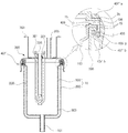
一方、本発明は、図6乃至図14のような実施例を適用することもできる。
本実施例の胴体部10は、図示の如く、内筒100と外筒200からなる二重壁の構造からなり、内筒100と外筒200は、アルミニウムやステンレススチールなどの金属材からなる。
On the other hand, the embodiments shown in FIGS. 6 to 14 can be applied to the present invention.
As shown in the figure, the
内筒100は、通常、略円筒形状からなり、一側が開放され、内部に前記貯水空間が設けられている。
The
そして、外筒200は、内筒100より大径を持つ、通常、円筒形状からなり、内筒100をその内部に収容するように配置される。
The
つまり、外筒200は、内筒100の外側を取り囲むように配置され、内筒100と外筒200の直径差分だけの間隔が内筒100と外筒200との間に形成される。
That is, the
内筒100と外筒200のそれぞれの開放側端部が相互接合して一体化することにより内筒100と外筒200の間には、前述した間隔だけの密閉空間部900が形成される。
The open side end portions of the
内筒100と外筒200の端部間の接合方式としては、溶接などの方式が用いられる。
As a joining method between the end portions of the
密閉された空間部900は、内筒100内に貯留された温水の保温維持のために断熱層としての機能を果たす。
The sealed
このように断熱層の機能を果たすように空間部900には空気層を形成することができ、望ましくは、温水槽内に貯留された温水の保温効率を極大化するように空間部900を真空状態にしたり、もしくは空間部900には保温材を充填することができる。
In this way, an air layer can be formed in the
空間部900を真空状態にするために、様々な真空形成方式が用いられることができるが、一例では、外筒200に真空抜きのための孔を形成し、接ぎ合わせることにより一体化となった内筒100及び外筒200を真空加熱炉に入れて真空加熱処理し、所定の真空度に到達したとき、この真空抜き孔を密封することによって、真空状態にすることができる。
Various vacuum forming methods can be used to make the
また、他の例では、真空抜きの孔に真空抜き装置を連結し、真空抜きを行い、所定の真空度に到達したら、真空抜き孔を密封することによって、真空状態を形成することも可能である。 In another example, it is possible to form a vacuum state by connecting a vacuum release device to the vacuum release hole, performing vacuum release, and sealing the vacuum release hole when a predetermined degree of vacuum is reached. is there.
空間部900に保温材(図示せず)を充填することもでき、この際、保温材としては、スタイロフォームや発泡ウレタンなどのような断熱性に優れた保温材や難燃性まで考慮した保温材などを用いることができる。
The
保温材を充填するというのは、先ず、内筒100の外面に密着して保温材を形成し、この状態の内筒100及び保温材を外筒200内に収容するが、この際、保温材の外面に外筒200の内面が密着して覆われるようにし、この状態で内筒100と外筒200の断部等が互いに接合し一体化することになり、空間部900に保温材が詰められることを意味する。
Filling the heat insulating material first forms a heat insulating material in close contact with the outer surface of the
カバー300もアルミニウムやステンレススチールのような金属材からなり、胴体部10の開放された一側、具体的に、内筒100の開放された一側を覆い、内筒100の内部の貯水空間を密閉させることになる。
The
カバー300は、カーリング加工や溶接などの方式を通じてカバー300の縁部を胴体部10の開放側縁部と結合することによって、胴体部10と組み合わされることができる。
The
図6は、カーリング加工形態の一例として、先ず、カーリング加工が容易に行われるように胴体部10の開放側縁部、具体的に外筒200と内筒100とが相互接合して一体化された部位を、胴体部10の外向きに折曲げ形成し、カバー300の縁部が胴体部10の折り曲げられた縁部を覆って圧着した例を示している。
FIG. 6 shows an example of a curling process. First, the open side edge of the
カーリング加工形態の例としては、前記した例に限られるものでなく、図7乃至図10に示したように、様々な形態にカーリング加工が行われえる。 Examples of the curling process form are not limited to the above-described examples, and the curling process can be performed in various forms as shown in FIGS.
具体的に、図7では、胴体部10の開放側の縁部にカバー300の縁部が巻き込まれたうえでカーリング加工され、胴体部10及びカバー300の相互結合部位の終端面が略円形を持つようにカーリング加工された形態の例を示している。
Specifically, in FIG. 7, the edge portion of the
図8では、図6に示したカーリング加工形態の例において、カバー300及び胴体部10の相互結合部位が下方に向かってもう一回折り曲げられ、外筒200の外面に密着するカーリング加工形態の例を示している。
8, in the example of the curling processing mode shown in FIG. 6, an example of the curling processing mode in which the mutual coupling portion of the
一方、カバー300は、カバー300の縁部が胴体部10の開放側縁部に溶接されることによって、胴体部10と結合されることもでき、溶接形態としては図9及び図10の例のように、様々な形態の例が提示されることができる。
On the other hand, the
一例で、図9では、胴体部10の開放側縁部、具体的に外筒200と内筒100が接合し一体化となった部位が、胴体部10の外向きに折り曲げ形成され、カバー300の縁部は、内筒100の上端の内周面及び折り曲げられた部位の上面と密着するように折り曲げ形成され、カバー300が胴体部10内に挿入されたように胴体部10の開放側を覆い、カバー300の縁端と胴体部10の開放側の縁端が相互隣り合うように接触させた後、この部位を溶接して結合させた例を示している。
For example, in FIG. 9, the open side edge of the
他の例として、図10では、図9のように、胴体部10の開放側の縁部に外向きに折り曲げられた部位を形成し、カバー300は、胴体部10の開放側に載置されたように胴体部10の開放側を覆い、カバー300の縁端と胴体部10の開放側の縁端と隣り合うように接触させた後、この縁端部を溶接して結合させた例を示している。
As another example, in FIG. 10, as shown in FIG. 9, a portion that is bent outward is formed at the opening side edge of the
前述したように、相互結合されたカバー300と胴体部10との結合部位にはパッキングPを介在する。
As described above, the packing P is interposed between the mutually coupled
パッキングPは、温水槽内における貯水空間の気密性を保持するために含まれるものであって、合成ゴムやシリコーン材からなる。 The packing P is included in order to maintain the airtightness of the water storage space in the hot water tank, and is made of synthetic rubber or silicone material.
前記カーリング加工や溶接は、胴体部10とカバー300との相互結合部位にパッキングPを介在した状態で行われることになる。
The curling process or welding is performed in a state where the packing P is interposed at the mutual coupling portion between the
一方、前記胴体部10には、その内部に貯蔵されている水を加熱するための様々な加熱手段が備えられ、図6乃至図10では、この加熱手段で胴体部10の貯水空間、具体的に内筒100内の貯水空間につながるようにカバー300の一側から貫通結合されるパイプヒーターのような温度制御具301の例を示している。
On the other hand, the
それに加え、胴体部10に貯蔵されている水の温度を測定するための温度センサー306が備えられ、図において、カバー300の表面にこの温度センサー306が備えられている。
In addition, a
但し、胴体部10及びカバー300を含めた水槽において、温度制御具301及び温度センサー306が設けられる位置は、図示の例に限定されるものではなく、様々な位置にて設けられることができる。
However, the position where the
そして、このような構造からなる水槽は、冷・温水器、浄水器、または自動販売機などの内部において固定ブラケット303により取り付けられることができる。
And the water tank which consists of such a structure can be attached by the fixed
図において、胴体部10の開放された一側が上方に向かった状態で固定ブラケット303がカバー300に備えられた例が示されている。
In the figure, an example is shown in which the
但し、固定ブラケット303の設置箇所や胴体部10の開放された一側が向かう方向は、図示の例に限定されるものではなく、胴体部10の開放された一側が下方を向いた状態でカバー300と組み合わされて取り付けられることも可能であり、固定ブラケット303も、必要に応じて様々な位置に設けられることができる。
However, the installation location of the fixing
前述した説明において、詳細に説明されていない図面符号304と305は、一般の温水槽に備えられている入水管と出水管をそれぞれ示したものであり、101は、ドレーン管を示すものである。
In the above description,
一方、本発明は、図11に示したような実施例の適用が可能である。 On the other hand, the embodiment as shown in FIG. 11 can be applied to the present invention.
即ち、本発明は、前記実施例と違って、胴体部10とカバー300が結合するという構造のものではなく、上部胴体部10uと下部胴体部10dが結合するという構造により温水槽が構成される。
That is, unlike the above embodiment, the present invention is not a structure in which the
下記において、上・下の胴体部の構造を主に説明するが、図面の符号等のうち、説明されていないものについては、前記実施例の説明に代えることにする。 In the following, the structure of the upper and lower body parts will be mainly described. Of the reference numerals and the like in the drawings, those not described will be replaced with the description of the embodiment.
本実施例は、下側が開放された円筒状の上部胴体部10uと、上側が開放され、上側縁が上部胴体部10uの下側縁と溶接により結合される円筒形状の下部胴体部10dを含む。そして、上部胴体部10uと下部胴体部10dとの結合部位には、パッキングPが介在する。
The present embodiment includes a cylindrical
特に、上部胴体部10uと下部胴体部10dは、前述した実施例の胴体部10と同じく二重壁の構造になっている。
In particular, the
即ち、上部胴体部10u及び下部胴体部10dそれぞれは、一側(上部胴体部10uに含まれる内筒100uにおいて下側をいい、下部胴体部10dに含まれる内筒100dにおいて上側をいう)が開放された円筒形状の内筒100u、100dと、これら内筒を取り囲むように配置される円筒形状の外筒200u、200dとからなる。
That is, each of the
そこで、内筒100u、100d及び外筒200u、200dそれぞれの端部が相互接合し一体化となり、内筒100u、100dと外筒200u、200dの間に密閉空間部900が形成される。
Therefore, the end portions of the
密閉された空間部900は、第1の実施例と同じく、温水槽の効率的な断熱のために、真空状態にするか、または保温材が充填されることができる。
As in the first embodiment, the sealed
そして、図11において、上部胴体部10uと下部胴体部10dの各周縁部が互いに溶接により組み合わされた状態を示しており、この結合方式は、特に限定されるものではなく、前述した実施例のように様々な形態からなるカーリング加工により結合されることもできる。
FIG. 11 shows a state in which the peripheral portions of the
一方、本発明は、図12及び図13のような実施例の適用が可能である。 On the other hand, the present invention can be applied to the embodiments as shown in FIGS.
本実施例は、前述した実施例と違って、胴体部10とカバー300が相互分離可能に組み合わされる温水槽の構造からなる。
Unlike the embodiment described above, this embodiment has a structure of a hot water tank in which the
具体的に、本実施例に含まれる胴体部10は、図6乃至図10で前記実施例のように同様の二重壁構造の胴体部10が含まれる。
Specifically, the
この際、胴体部10における内筒100と外筒200の間の空間部900には、スタイロフォームや発泡ウレタンなどのような断熱性に優れた保温材や難燃性まで考慮した保温材などが充填されることができる。
At this time, the
但し、胴体部10の開放側の外周面に円周方向に沿って形成される胴体結合部10cをさらに含み、胴体結合部10cの外周面には螺子山100sが形成される。
However, it further includes a
そして、胴体部10の開放側を覆うように結合するカバー300は、その外周面において円周方向に沿って形成され、胴体結合部10cと螺合することができるカバー結合部300cをさらに含み、カバー結合部300cの内周面には胴体結合部10cのねじ山100sに螺合するための螺子溝300sが形成される。
And the
このように、本実施例の胴体部10とカバー300に胴体結合部10c及びカバー結合部300cがそれぞれ形成され、互いに螺合することによって、胴体部10とカバー300が相互分離可能に結合されることができる。
As described above, the
そして、相互結合する際、互いに近接することになる胴体部10の開放側縁部とカバー300の縁部との間には、胴体部10内の気密性を保持するためにパッキングPが介在されることができる。
Further, a packing P is interposed between the open side edge portion of the
この際、胴体部10及びカバー300の各縁部にはパッキングPを加圧する面積が広くなるように外向きに円弧状に折り曲げられた折曲部が形成されることができる。
At this time, a bent portion that is bent outward in an arc shape so that an area to pressurize the packing P may be formed at each edge portion of the
そして、パッキングPは、図12に示したように、パッキングPの外周面上において円周方向に沿って複数の突起部300pが形成され、胴体部10とカバー300相互間の気密性がより向上できる。
In the packing P, as shown in FIG. 12, a plurality of
また、パッキングPは、円周方向に沿って、下方に向けて2回直角に折り曲げられる係止片300hが形成され、胴体部10の縁端部に引っ掛かるように結合されることができ、これにより、解体及び組立の際、パッキングPの結合又は分離が容易となる。
In addition, the packing P is formed with a
本実施例による構造が、前述した如く、分離可能な構造、具体的に胴体結合部10cとカバー結合部300cをさらに含むことによって、胴体部10及びカバー300は、図6乃至11に示された実施例のように相互カーリング加工や溶接により結合されなくてもよいので、金属素材に限定されない。つまり、金属素材からなることも可能であり、セラミック素材から作製されることもできる。
As described above, the structure according to the present embodiment further includes a separable structure, specifically, the
胴体部10とカバー300が、金属材から作製されたものとして、胴体結合部10cとカバー結合部300cが、プラスチック材から作製される場合には胴体結合部10cとカバー結合部300cが胴体部10及びカバー300にそれぞれ結合するという方式として、インサート射出又は強制圧入方式が用いられる。
Assuming that the
この際、胴体結合部10c及びカバー結合部300cが胴体部10及びカバー300に対して遊動することなく堅固に結合できるように、胴体部10の外周面及びカバー300の外周面それぞれには突起形状の構造を設けることができる。
At this time, each of the outer peripheral surface of the
図示されていないが、胴体部10とカバー300がセラミック材から作製される場合は、胴体結合部10cとカバー結合部300cもセラミック材からなると共に一体化して形成されることができる。
Although not shown, when the
そして、胴体部10の内筒100と外筒200は、図6乃至図10に示された実施例のように、各端部が、溶接などにより接合し一体化されるのでなく、互いに一体に形成されながら、内筒100と外筒200の間に空間部900が備わるように成形されることができる。
And the
また、本実施例は、図12に示されていないが、図13の如く、胴体部10内に収容された水が持っている熱エネルギーがカバー300の方に損失することを最小限に止めるべく、カバー300の上部に覆われている、優れた難燃性及び断熱性を持つ保温材300iがさらに含まれることができる。
Further, although this embodiment is not shown in FIG. 12, as shown in FIG. 13, the loss of heat energy held by the water contained in the
一方、本発明は、図14のような構造の適用も可能である。即ち、本実施例は、図12及び図13に示された実施例と同じく、カバー300と胴体部10がねじ結合方式により分離可能に組み合わされる温水槽の構造からなる。
On the other hand, the present invention can be applied to the structure shown in FIG. That is, this embodiment has a structure of a hot water tank in which the
カバー300の構造は、第3実施例と同様であるが、但し、第3の実施例と違って、胴体部10の構造において相違があるため、下記では、相違点のある胴体部10の構造に関して主に説明をすると共に、図面符号等のうち、説明されていないものについては、前述した実施例などの説明に代えることとする。
The structure of the
本実施例の胴体部10は、図6乃至図13に示した実施例と同じく、二重壁の構造、つまり内筒100と外筒200からなるが、内筒100と外筒200の各端部が相互接合し一体化されず、外筒200が内筒100の外周面に形成された胴体結合部10cに挿入結合する構造となっている。
The
具体的に、内筒100の開放側の外周面には、図12及び図13に示された実施例と同じ機能を奏する胴体結合部10cが形成される。
Specifically, on the outer peripheral surface on the open side of the
この際、胴体結合部10cの一側、具体的な例として、胴体結合部10cの外周面の下端部には垂直下方に延びる嵌入部100sbが胴体結合部10cの円周方向に沿って形成される。
At this time, one side of the
そして、外筒200は、この嵌入部100sbの外周面が外筒200の開放側端部の内周面と面接触しながら、嵌入部100sbに結合することになる。
The
この際、嵌入部100sbの外周面には、円周方向に沿って嵌合突起100sbpが少なくとも一つ以上(図14では嵌入部100sbの外周面上で上下方向に離隔する二つの嵌合突起100spbが形成された例を示している)突出形成されることができ、この嵌合突起100sbpに対応して外筒200の端部の内周面には嵌合溝100gが形成されることができる。
At this time, at least one fitting protrusion 100sbp is provided along the circumferential direction on the outer peripheral surface of the fitting portion 100sb (in FIG. 14, two fitting protrusions 100spb separated in the vertical direction on the outer peripheral surface of the fitting portion 100sb. A
外筒200と嵌入部100sbは、嵌合溝100gとこの嵌合溝100g に嵌合する嵌合突起100sbpにより外筒200が元の位置を容易に探すことが可能であり、堅固で安定的に嵌合することができる。
The
外筒200と内筒100との間の空間部900は、嵌合溝100sbと内筒100との間の隙間だけ形成され、この空間部900を真空状態にするか、空間部900内を保温材で充填することができる。
A
一方、パッキングPは、内筒100の開放側の縁部とカバー300の縁部から外向きに円弧形状に折り曲げられる縁部に沿って介在する。
On the other hand, the packing P is interposed along the edge of the
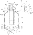
一方、胴体部10は、図15乃至図26のように、断熱性能の向上のために二重の構造を適用することができ、具体的には、内筒100と外筒200を含む構造を適用することができる。
On the other hand, as shown in FIGS. 15 to 26, the
内筒100は、水を収容するための空間であり、外筒200は、内筒100の外面との間に空間部900を形成しながら、内筒100を取り囲む構造からなり、後述するカバー300は、内筒100及び外筒200を仕上げ、気密保持部400は、内筒100とカバー300との間、又は外筒200とカバー300との間に装着され、内筒100及び外筒200の密封状態を保持する構造である。
The
ここで、外筒200は、内筒100の開放された一側の縁部と一体に結合され、外筒200の内面と内筒100の外面との間は、断熱性能を向上させるために真空状態を維持することが望ましい。
Here, the
この際、内筒100と外筒200は、成形の利便性や耐久性などを考慮し、ステンレススチールやアルミニウムなどの金属材から作製されることができる。
At this time, the
さらに、内筒100及び外筒200は、ガラス、陶器、琺瑯など、多様な材料から作製されることが可能である。
Furthermore, the
また、空間部900は、真空状態を保持することによって、外筒200の外面は、熱伝導率が最大限低下するので、内筒100内に収容された水は、保温又は保冷が可能となる。
Moreover, since the
一方、気密保持部400は、図示のような内筒100及び外筒200の二重構造である胴体部10で図15及び図16のように第1結合体406と、第2結合体407及びパッキング408を含む構造を適用することができる。
On the other hand, the airtight holding
即ち、第1結合体406は、外筒200の外側縁部に結合し、外周面に沿って螺子部406sが形成され、第2結合体407は、カバー300の外側面に結合し、第1結合体406と螺合するように内周面に沿って螺子部407sが形成され、パッキング408は、胴体部10の端部とカバー300の内側縁部の間に介在され、胴体部10の内部が密閉されるようにする役割を果たす。
That is, the
そこで、外筒200には、第1結合体406の一側を支持するように外筒200の外周面に沿って支持突起200pが突出形成され、カバー300には第2結合体407の一側を支持するようにカバー300の外周面に沿って支持突起300pが突出形成されるという構造が適用される。
Therefore, the
この際、第2結合体407は、カバー300と胴体部100が結合するとき、第1結合体406を覆いながら、螺子部406s、407s相互間の螺合が行われるのである。
At this time, when the
また、パッキング408は、ゴム又はシリコーン材のものを用いることができ、縦断面がO形である、Oリングを含み、多様な形状のものを適用することができる。 In addition, the packing 408 can be made of rubber or silicone material, and can have various shapes including an O-ring whose longitudinal section is O-shaped.
胴体部10の端部には、パッキング408が結合するように外側に向けて折り曲げられた第3の折曲部15が形成されることができ、図16では、内筒100及び外筒200の開放された一側の端部が一体に折り曲がることにより、第3の折曲部15が形成された例を示す。
A third
カバー300には、縁部に沿ってパッキング408が圧着固定されるように、第3の折曲部15に対面して折り曲げられる第4の折曲部35が形成されることが望ましく、第3の折曲部15及び第4の折曲部35の何れか一方の一側またはそれぞれの一側にはパッキング408の側に突出した突出部がさらに含まれる構造を適用するようにし、図16では、第3の折曲部15から突出された突出部15´の構造を示す。
The
パッキング408は、図15及び図16のように、下側に第3の折曲部15の外側端部が結合されるように、縦断面が略コ字状からなり、このようなパッキング408は、第3の折曲部15の上面を覆いながら嵌入結合されるので、胴体部10を洗浄するとき、パッキング408の着脱が容易である。
15 and 16, the packing 408 has a substantially U-shaped longitudinal section so that the outer end of the third
そして、パッキング408は、第3の折曲部15または第4の折曲部35の側に向かって第3又は第4の折曲部15、35に対向する面に沿ってリング状の突起線409が少なくとも一つ以上突出され、第3の折曲部15または第4の折曲部35に対向する面に沿って突起線409の内側又は外側に複数の小突起408´が離隔して突き出されており、胴体部10とカバー300の間における締結力を強化させることができる。
The packing 408 has a ring-shaped protruding line along a surface facing the third or fourth
また、パッキング408の内側端部には、胴体部10とカバー300の内側縁部と当接しながら気密保持をさらに確実に維持するために上・下方に延びる延長部409´が一体に形成されることが望ましい。
In addition, an
したがって、第4の折曲部35は、パッキング408に対して加圧される面積が広くなるにつれ、胴体部10の密閉性が増強するのである。
Therefore, as the area where the fourth
一方、気密保持部400は、図17及び図18のように、係止部406´と締結部407´及びパッキング408を含む構造を適用することもできる。
On the other hand, as shown in FIGS. 17 and 18, the
即ち、係止部406´は、外筒200の外側縁に組み合わされ、一側に係止突起406´pが突出形成され、締結部407´は、固定体407´aと係止片407´hが形成された羽根体407´bを含んで係止部406´と結合され、パッキング408は、胴体部10の端部とカバー300の内側縁部との間に介在し、胴体部10の内部が密閉されるようにする役を果たす。
That is, the locking
これらのうち、締結部407´の固定体407´aは、カバー300の外側面に取り付けられており、羽根体407´bは、固定体407´aの縁部に沿って回動可能に延長され、係止突起406´pと係合する係止片407´hが外筒200の外面側に向かって突き出された構造である。
Among these, the fixing
固定体407´aと羽根体407´bの連結は、ヒンジピンによりヒンジ結合(図示せず)されるなどの様々な連結方式が用いられる。
For the connection between the
但し、図において、締結部407´がプラスティック材などからなり、固定体407´aと羽根体407´bが、その連結部位において薄厚になるようにして、上・下方に回動可能な一体構造を示している。
However, in the figure, the
係止片407´hは、羽根体407´bが胴体部10側に回動するにつれ係止突起406´pに引っ掛かりながら結合が行われ、続いて胴体部10の外面、さらに詳しくは外筒200の外面側から遠くなると、結合が解体される。
The locking piece 407'h is coupled while being hooked on the locking projection 406'p as the blade body 407'b rotates toward the
この際、固定体407´aと羽根体407´bの連結箇所から係止片407´hまでの直線距離は、同じ地点の水平線上で係止部406´の低部の外側方に形成される係止突起406´pの下端までの距離より多少短いため、係止片223は、係止突起406´pの下端を超えることによって引っ掛かることになっている。
At this time, the linear distance from the connecting portion of the fixed
係止片407´hが、このように係止突起406´pに引っ掛かるようになると、カバー200は、胴体部10に圧着しながら結合することになる。
When the
ここで、締結部407´は、カバー300の縁部に沿って少なくとも二つ以上形成されるのが望ましく、羽根体407´bの回動において利便性を与え、外筒200の外面に沿って締結部407´による圧着力がバランスよく与えられるように一つの締結部407´に対向する位置にもう一つの締結部407´が備えられることが望ましい。
Here, it is desirable that at least two
一方、第3の折曲部15と第4の折曲部35は、図10のような構造を適用することができる。
On the other hand, the structure as shown in FIG. 10 can be applied to the third
即ち、第3と第4の折曲部15、35には、溝15´´、35´´がそれぞれ形成されており、前述した溝15´´、35´´の両側縁は、突き出される形状になっている。
That is,
第3と第4の折曲部15、35が、前述した形状からなっていることによって、パッキング408が介在するとき、溝15´´、35´´の両側が、突出部位によりパッキング408が集中的に押圧されることが可能であり、このことから密閉性がさらに向上する。
Since the third and fourth
一方、前述した実施例の他にも、気密保持部400は、図20乃至図26に示しているように内筒100とカバー300との間、又は外筒200とカバー300との間に組み付けられるものであって、仕上げ面とシール部材を含む。
On the other hand, in addition to the embodiment described above, the
これから説明する他の実施例は、仕上げ面とシール部材を含む気密保持部400に関するものであって、仕上げ面は、カバー300の縁部に沿って延長され、内筒100又は外筒200に組み合わされると共に、シール部材は、仕上げ面に取り付けられ、内筒100又は外筒200に当接しながら気密の状態を維持する役割を奏する。
Another embodiment to be described below relates to an
以下の説明において、用いられる用語について簡単に説明する。 In the following description, terms used will be briefly described.
まず、「外側縁部」と「内側縁部」とは、溶接により一体形をなす内筒100と外筒200の縁部を基準にして前記縁部に近い内側及び外側の部分をいい、後述するシール部材が密着する部位を示す。
First, the “outer edge portion” and the “inner edge portion” refer to inner and outer portions close to the edge portion based on the edge portions of the
そして、「端部側の内面」と「端部側の外面」は、溶接により一体形をなす内筒100と外筒200の内面または外面において、後述する仕上げ面と対面して結合することになる内面、または外面を示す。
And, “the inner surface on the end portion side” and “the outer surface on the end portion side” are bonded to each other on the inner surface or the outer surface of the
先ず、図20のように、カバー300の仕上げ面410は、外筒200と螺合し、シール部材420は、外筒200の外側縁部に当接する構造を適用できる。
First, as shown in FIG. 20, a structure in which the
即ち、カバー300は、内筒100の開放された一側を密閉する遮蔽板310と、遮蔽板310の縁部に沿って遮蔽板310と仕上げ面410との間に形成され、内筒100の内側縁部に対面する接触溝320を含む形態に作製されることができる。
That is, the
接触溝320は、カバー300に装着された温度制御具301及びサーモスタット302などによる荷重と応力を適切に分散する、補強の目的で形成される。
The
ここで、仕上げ面410は、外筒200の端部側の外面と螺合し、シール部材420は、接触溝320と仕上げ面410との間に介在し、内筒100の縁部と外筒200の外側縁部に密着されることによって、気密の保持が可能である。
Here, the
一方、本発明では、カバー300の仕上げ面は、内筒100に螺合し、シール部材は、内筒100の内側に接触するという構造を適用でき、これに対して図21及び図22を参考として説明する。
On the other hand, in the present invention, a structure in which the finish surface of the
先ず、カバー300は、図21のように、内筒100の開放された一側を密閉する遮蔽板310と、遮蔽板310の縁部に沿って遮蔽板310と仕上げ面430との間に形成され、内筒100の内側縁部に対面する接触溝330と、仕上げ面430の端部から延びて折り曲げられ、シール部材440が装着され、外筒及び内筒100の縁部を覆う仕上げスリーブ340を含む形態に作製することができる。
First, as shown in FIG. 21, the
接触溝330は、カバー300に装着された温度制御具301及びサーモスタット302などによる荷重と応力を適切に分散するという補強の目的で形成され、仕上げ面スリーブ340は、シール部材440が装着されるための空間を提供すべく設けられる。
The
そこで、仕上げ面430は、接触溝330の縁部から延びて内筒100の端部側の内面と対面して相互螺合することになり、シール部材440は、一側が内筒100及び外筒200の縁部に密着し、他側が内筒100の内側縁部に密着することによって、気密の保持が可能である。
Therefore, the finishing
そして、カバー300は、図22の如く、内筒100の開放された一側を密閉する遮蔽板310と、仕上げ面450の端部から延びて折り曲げられ、シール部材460が装着され、外筒200及び内筒100の縁部を覆う仕上げスリーブ350を含む形態に作製されることができる。
Then, as shown in FIG. 22, the
仕上げスリーブ350は、シール部材460を装着するための空間を提供するために設けられる。
The finishing
そこで、仕上げ面450は、内筒100の端部側の内面に対面して相互螺合し、シール部材460は、一側が内筒100及び外筒200の縁部に密着し、他側が内筒100の内側縁部に密着することによって、気密の保持が可能となる。
Therefore, the finishing
そして、カバー300は、図23の如く、内筒100の開放された一側を密閉する遮蔽板310と、仕上げ面470の端部から延びて折り曲げられ、外筒200及び内筒100の縁部を覆う仕上げスリーブ360と、仕上げ面470の外面に沿って形成され、シール部材480が嵌入するための谷部370とを含む形態に作製されることができる。
Then, as shown in FIG. 23, the
仕上げスリーブ360は、一体形になっている内筒100及び外筒200の縁部等の溶接部位を外部の物理、化学的衝撃から保護するために設けられる。
The finishing
谷部370は、シール部材480が装着されるための空間を提供すために設けられる。
The
ここで、仕上げ面470は、内筒の端部側の内面と対面して相互螺合し、シール部材480は、谷部370に装着され、内筒100の端部側の内面に密着されることによって、気密の保持が可能となる。
Here, the finishing
そして、カバー300は、図24の如く、内筒100の開放された一側を密閉する遮蔽板310と、仕上げ面470の端部から延びて折り曲げられ、外筒200及び内筒100の縁部を覆う仕上げスリーブ360と、仕上げ面470の外面に沿って形成される谷部370とを含む形態に作製されることができる。
Then, as shown in FIG. 24, the
仕上げスリーブ360と谷部370は、シール部材480がそれぞれ装着されるための空間を提供するために設けられる。
The finishing
ここで、仕上げ面470は、内筒100の端部側の内面に対面して相互螺合し、シール部材480は、内筒100及び外筒200の縁部に密着し、内筒100の端部側の内面にそれぞれ密着するという方式で、気密の保持が可能となる。
Here, the finishing
この際、シール部材480は、仕上げスリーブ360に装着され、一側が内筒100及び外筒200の縁部に密着し、他側が内筒100の内側縁部に密着する第1のシーリング具482と、谷部370に装着され、内筒100の端部側の内面に密着するリング状の第2のシーリング具484とを含む構造を適用することができる。
At this time, the
一方、本発明では、図25の如く、溶接により一体化をなす内筒100及び外筒200の縁部と仕上げ面490のと間にシール部材490´を介在させる構造を適用することができる。
On the other hand, in the present invention, as shown in FIG. 25, a structure in which a
また、カバー300は、内筒100の開放された一側を密閉する遮蔽板310と、遮蔽板310の縁部に沿って遮蔽板310と仕上げ面490との間に形成され、内筒100の内側縁部に対面する接触溝380とを含んで作製されることができる。
The
ここで、仕上げ面490は、接触溝380の縁部から遮蔽板310に対して平行に延びて、シール部材490´は、溶接により結合され、一体形をなす内筒100及び外筒200の縁部から延びて仕上げ面490に対面する折曲面490´´間に密着するという方式で気密の維持が可能となる。
Here, the finishing
この際、カバー300には、接触溝380と仕上げ面490に一側が結合され、折曲面490´´と外筒200の外面の間に他側が結合される密閉リングブロック600により、カバー300と内筒100及び外筒200を密閉するように構成し、密閉リングブロック600は、第1のリングブロック610と第2のリングブロック620を含む。
At this time, the
第1のリングブロック610は、全体的にリング状をなしており、接触溝380に対応する形状のリング突起612が設けられ、リング突起612から延びて、仕上げ面490が収容されるための仕上げ溝614が設けられる構造からなる。
The
第2のリングブロック620も、第1のリングブロック610のように全体的にリング状をなしており、折曲面490´´が取り付けられるための取付段622が設けられ、第1のリングブロック610が結合するようになる構造からなる。
The
第1のリングブロック610と第2のリングブロック620は、望ましくは、これらリングブロック610、620の形成方向に沿って離隔して装着される複数の固定ボルト630により相互貫通して結合される。
The
一方、外筒200の一側には内筒100と外筒200の間の残留空気が排出されるための真空保持部500がさらに含まれるのが望ましく、真空保持部500は、内筒100と外筒200の縁部を相互溶接し、一体形に作製したあと、空間900を真空状態にするために必要となるものであり、メンテナンスのためにも必要な部分である。
Meanwhile, it is desirable that one side of the
真空保持部500は、外筒200の外側に設けられる空気排出管510と、外筒200の一側に結合し、空気排出管510を保護する保護カバー520とを含む構造であることがわかる。
It can be seen that the
また、本発明は、図1と共に、図27乃至図29に示したように、外筒200の外面に耐圧力具を形成し、カーリング加工と溶接または充填材Pなどで気密保持部400を形成する実施例を適用することはもちろんである。
Further, according to the present invention, as shown in FIGS. 27 to 29 together with FIG. 1, the pressure-resistant tool is formed on the outer surface of the
即ち、外筒200の外面には、図示の如く、空気排出管510を通じて残留空気が排出されると、空間部900内外側の圧力がバランスをなし、内筒100及び外筒200の形状を維持するための耐圧力具が形成されることが望ましい。
That is, on the outer surface of the
耐圧力具は、空間部900内外側の圧力がバランスをなし、内・外筒100、200の形状を維持するために設けられたものであって、第1の突起リング210と第2の突起リング534を含む構造である。
The pressure-resistant tool is provided in order to maintain the balance between the inner and outer pressures of the
耐圧力具は、後述する真空保持部500を通じて空間部900の真空状態の保持のために残留空気を排出させる過程で空間部900内外側の圧力のアンバランスにより内・外筒100、200の形状が変形するのを防止するという目的のほかに全体的な構造的強度を向上させるためにも設けられる。
The pressure-resistant tool is formed in the shape of the inner and
第1の突起リング210は、外筒200の外面に上下方向に少なくとも一つ以上の外周面に沿ってリング状に突き出されたものであり、第2の突起リング534は、内筒100の底面の中央から連通したドレーン管101が中央を貫通している外筒200の底面530に設けられ、前記ドレーン管101を中心にして、同心円状に少なくとも一つ以上突出されたものである。
The first
第1、2突起リング210、534は、同じ単位面積当たり突出構造やひだ(襞)の箇所を備えておらず、滑らかで平らなパネルに比べて実質的な面積がひだ構造などにより増加したパネルが構造的強度の点でより高いことに起因して、外筒200の外周面及び底面にそれぞれ設けられる。
The first and second protrusion rings 210 and 534 do not have the same protruding structure or pleats (creases) per unit area, and have a substantial area increased by a pleat structure compared to a smooth and flat panel. Are provided on the outer peripheral surface and the bottom surface of the
一方、カバー300は、前述したように胴体部10を仕上げるためのもので、図1、図27及び図28のように、縁部に沿って胴体部10の内側に向けて陥没された谷部307がリング形状に形成され、後述する気密保持部400は、谷部307の縁部から延び、胴体部10の縁部に谷部307が嵌入し結合された後、カーリング加工、パッキング材Pの充填または溶接などの方法により堅固に気密状態を保持することになる。
On the other hand, the
谷部307は、カバー300と胴体部10とを最初に結合する過程において堅固に締結すると共に、前記耐圧力具のようにカバー300に装着された各種部材などの荷重を効率よく分散支持することができ、構造的強度を向上させるために設けられたものであって、一側壁307´と底部307´´と他側壁307´´´とからなる。
The
一側壁307´は、カバー300の縁部から延びて胴体部10の内側にカバー300と直角をなすように折り曲げられ、底部307´´は、一側壁307´の端部から延びてカバー300に対して平行に折り曲げられ、他側壁307´´´は、底部307´´から延びて一側壁307´に対して平行に折り曲げられて形成される。
The one
ここで、後述する気密保持部400は、他側壁307´´´の縁部から延び、他側壁307´´´の外面は内筒100の内壁に接触する。
Here, the
この時、カバー300にはスチームベント管308が貫通されるのが望ましく、スチームベント管308は胴体部10が温水槽として用いられるとき、内筒100内の水を加熱することにより生じるスチームが出水管305に混入したり、逆流したりすることを防止すべく、スチームを上部側に強制排出させるために設けられる。
At this time, it is desirable that the
一方、気密保持部400は、前述したように胴体部100とカバー300の相互間の気密状態を維持するために設けられたものであって、図27の如く、第1の折曲部45と第6の折曲部65及び溶接結合部Wとパッキング材Pを含む構造を適用することができる。
On the other hand, the airtight holding
第5の折曲部45は、内筒100の開放側縁部と外筒200の開放側縁部が相互当接してなされた結合面が、外筒200の外側に向かってフランジ状に折り曲げられて設けられる部分である。
In the fifth
第6の折曲部65は、カバー300の縁部、即ち、谷部307の他側壁307´´´の縁部から延びて、前記結合面の上・下部を、「⊂」または「⊃」の形状に覆うように形成される部分で、実質的な気密状態を維持する部分でもある。
The sixth
溶接結合部Wは、第5の折曲部45の端部、つまり、内筒100及び外筒200の端部が接触する部位に沿って溶接を施して設けられた部分であり、空間部900へ外気が流入することを防止するために形成される。
The weld joint W is a portion provided by welding along the end of the fifth
パッキング材Pは、前記結合面の上面と第6の折曲部65との間に詰められるものであって、通常、シリコーンなどのような材質を用いるが、詳しくは、第6の折曲部65及び前記結合面の形成方向に沿ってそれぞれシリコーンを塗布し、堅くなると、カバー300と胴体部10を相互結合させた後、第6の折曲部65をカーリング加工などの方法を通じて形成することになる。
The packing material P is packed between the upper surface of the coupling surface and the sixth
そして、気密保持部400は、図28の如く、第1結合部46に別の補強片55を組み合わせ、次いで溶接し、パッキング材Pを充填したあと、第6の折曲部65を形成するという構造の実施例を適用できる。
Then, as shown in FIG. 28, the
即ち、第1の結合部46は、内筒100の開放側縁部と外筒200の開放側縁部が相互当接してなされた結合面により形成される部分であって、後述する補強片55と溶接結合部Wが形成される部分でもある。
That is, the
補強片55は、前記結合面の外側縁部に沿って結合するリング形状のものであり、溶接が容易に行われるように内筒100及び外筒200と同じ系の材質を適用することが望ましい。
The reinforcing
溶接結合部Wは、第1結合部46と補強片55が当接する部位に沿ってリング状に溶接を実施することによって設けられた部分であり、第1結合部46の形成方向に沿って空間部900の側へ外気が流入することを遮断し、後述する第6の折曲部65が形成されるための空間を提供する補強片55が組み合わされるようにするために形成される。
The weld joint portion W is a portion provided by performing welding in a ring shape along a portion where the first
第6の折曲部65は、前記結合面の内側面に沿って接するカバー300の縁部、つまり谷部307の他側壁307´´´の縁部から延びて、前記結合面の端部と補強片55の上・下部を覆うように形成され、補強片55の上部と第2折曲部65との間にはパッキング材Pが詰められる。
The sixth
そこで、図27(カバー300の上面から延びる、点線の仮想線参照)及び図28に示した第2の折曲部65の上面は、谷部307を基準として、水が漏水することが生じてもカバー300の上面に装着された電気装置等に水が当たることがないように温度センサー306などの電気装置が装着されているカバー300の上面に比べて同様に形成されるか、あるいは低く形成されるようにすることが望ましい。
Therefore, in FIG. 27 (see the dotted phantom line extending from the upper surface of the cover 300) and the upper surface of the second
また、気密保持部400は、図29のように第1結合部46に補強片55を結合し、カバー300の縁部と溶接を施すことにより形成される実施例を適用することができる。
Moreover, the airtight holding |
即ち、第1結合部46は、内筒100の開放側縁部と外筒200の開放側縁部が相互当接してなされた結合面により形成された部分であり、後述する補強片55と溶接結合部Wが形成される部分でもある。
That is, the
補強片55は前記結合面の外側縁部に沿って結合されるリング状のものであって、通常、溶接が行われ得るように内筒100及び外筒200と同じ系の材質を適用することが望ましい。
The reinforcing
第2の結合部66は、カバー300の縁部と補強片55が面接触して形成される部分であり、第1結合部46と補強片55が当接する部位に沿ってリング状に溶接を実施することにより第1の溶接結合部W1が設けられ、第1結合部46と第2結合部65の端部に沿ってリング状に溶接を実施し、第2の溶接結合部W2が設けられる。
The
第1の溶接結合部W1は、第1結合部46の形成方向に沿って空間部900の側に外気が流入することを遮断し、後述する第6の折曲部65が形成される空間を提供する補強片55が組み合わされるようにするために形成される。
The first weld joint portion W1 blocks outside air from flowing into the
この際、第2の溶接結合部W2は、最終的に胴体部10とカバー300相互間を密封することによって気密状態を維持するために形成される。
At this time, the second weld joint portion W2 is formed in order to maintain an airtight state by finally sealing between the
また、カバー300の上面には第2結合部66が形成されるための補強片55の内側縁に沿って突出する補強用リング突起308が形成されるようになっている構造を適用でき、補強用リング突起308は、谷部307のように構造的強度を向上させるための目的で設けられる。
Further, a structure in which a reinforcing
一方、真空保持部500は、前述したように継続して断熱効果を維持するためには胴体部10の熱伝導率を最大限に低くすることが最も重要であり、このためには、空間部900が真空状態に近くなるようにする必要があるので、設けられたものといえる。
On the other hand, in order to maintain the heat insulating effect continuously as described above, it is most important for the
そのうえ、保護カバー520を、図1及び図27を参照すると、望ましくは、空気排出管510を通じて空間部900内の残留空気を排出させ、別の仕上げ具(図示せず)で空気排出管510を密封した後、前記空気排出管510を覆う、次のような構造からなる。
In addition, referring to FIG. 1 and FIG. 27, the
即ち、保護カバー520は、外筒200の外部側の外面と着脱結合する筒壁521と、筒壁521の下端縁部から、内筒100の底面中央から連通したドレーン管101の側に向けて延長され、中央が貫通された底面521´と、底面521´の貫通された中央の縁部から外筒200の底面530に向けて延長され、外筒200の底面530に密着される接触角(つの、horn)523とを含む構造を適用することができる。
That is, the
即ち、前記保護カバー520の構造は、長時間の使用により空間部900の真空状態が弱まった場合、空気排出管510を通じて真空ポンプなどで空間部900内の残留空気を排出させる必要がある時に着脱結合が可能となるようになっている構造である。
That is, the structure of the
ここで、接触角523の縁端部は、外筒200の底面530からドレーン管101を中心としてリング状に突出された接触リング突起532に密着して固定されるのが望ましい。
Here, the edge portion of the
この時、保護カバー520の構造について詳述すると、外筒200の下部側の外面に沿って段差が形成された結合段差面220に着脱結合することがわかる。
At this time, when the structure of the
図27において、説明されていない符号230は、第2の突起リング534が形成された外筒200の底面530を外筒200の外周面に結合するために設けられた仕上げスリーブを示す。
In FIG. 27,
保護カバー520の筒壁521には、結合段面220の側に向けて外周面に沿って陥没された第1の係止リング溝522が設けられ、結合段面220には第1の係止リング溝522が対応する位置に内筒100の側に向けて陥没された第2の係止リング溝222が設けられ、第1、2の係止リング溝522、222が相互結合することにより密閉される構造である。
The
以上のように、本発明は、水槽内の洗浄が容易になされると共に気密の維持が確実に行われ、断熱性能を高くし、水槽内の水を加熱または冷却させるためのエネルギー消耗量を最小限に抑えることができるようにする、気密保持部が備えられた水槽を提供することを基本的な技術的思想としていることがわかる。 As described above, the present invention facilitates cleaning of the water tank and ensures airtightness, enhances heat insulation performance, and minimizes energy consumption for heating or cooling the water in the water tank. It can be seen that the basic technical idea is to provide a water tank provided with an airtight holding portion that can be suppressed to the limit.
以上で、本発明による実施例について説明したが、これら実施例は、例示的なものに過ぎず、該当技術分野における通常の知識を有する者であれば、様々な変形及び均等範囲内の実施例が可能であることを理解するだろう。 The embodiments according to the present invention have been described above. However, these embodiments are merely illustrative, and various modifications and embodiments within the equivalent scope can be used by those having ordinary knowledge in the technical field. You will understand that is possible.
したがって、本発明の技術的保護範囲は、添付の特許請求範囲により定められるべきである。 Therefore, the technical protection scope of the present invention should be determined by the appended claims.
10 胴体部
15 第3の折曲部
15´ 突出部
15´´、35´´ 溝
35 第4の折曲部
45 第5の折曲部
46 第1の結合部
55 補強片
65 第6の折曲部
66 第2の結合部
100 内筒
101 ドレーン管
140 拡管部
160 固定枠
200 外筒
210 第1の突起リング
220 結合段面
222 第2の係止リング溝
230 仕上げスリーブ
300 カバー
301 温度制御具
302 サーモスタット
303 固定用ブラケット
304 入水管
305 出水管
306 温度センサー
307 谷部
307´ 一側壁
307´´ 底部
307´´´ 他側壁
310 遮蔽板
320、330、380 接触溝
340、350、360 仕上げスリーブ
370 谷部
400 気密保持部
401 第1の折曲部
402 他側壁
403 底部
404 一側壁
405 第2の折曲部
406 第1の結合体
406s 螺子部
407 第2の結合体
407s 螺子部
408 パッキング
408´ 小突起
409 突起線
409´ 延長部
406´ 係止部
406´p 係止突起
407´ 締結部
407´a 固定体
407´b 羽根体
407´h 係止片
410、430、450、470、490 仕上げ面
420、440、460、480、490´ シール部材
482 第1のシリング具
484 第2のシリング具
490´´ 折曲面
500 真空保持部
510 空気排出管
520 保護カバー
521 筒壁
521´ 底面
522 第1の係止リング溝
523 接触角(つの)
530 底面
532 接触リング突起
534 第2の突起リング
600 密閉リングブロック
610 第1のリングブロック
620 第2のリングブロック
630 固定ボルト
900 空間部
10 body part 15 3rd bending part 15 'protrusion part 15'',35''groove 35 4th bending part 45 5th bending part 46 1st connection part 55 reinforcement piece 65 6th folding Curved portion 66 Second connecting portion 100 Inner tube 101 Drain tube 140 Expanded portion 160 Fixed frame 200 Outer tube 210 First protruding ring 220 Connecting step surface 222 Second locking ring groove 230 Finishing sleeve 300 Cover 301 Temperature control tool 302 Thermostat 303 Fixing bracket 304 Water inlet pipe 305 Water outlet pipe 306 Temperature sensor 307 Valley 307 ′ One side wall 307 ″ Bottom side 307 ″ ″ Other side wall 310 Shielding plates 320, 330, 380 Contact grooves 340, 350, 360 Finishing sleeve 370 Valley portion 400 Airtight holding portion 401 First bent portion 402 Other side wall 403 Bottom portion 404 One side wall 405 Second bent portion 406 First combined body 06s Screw part 407 Second combined body 407s Screw part 408 Packing 408 ′ Small protrusion 409 Projection line 409 ′ Extension part 406 ′ Locking part 406′p Locking protrusion 407 ′ Fastening part 407′a Fixed body 407′b Blade body 407'h Locking piece 410, 430, 450, 470, 490 Finished surface 420, 440, 460, 480, 490 'Seal member 482 First shilling tool 484 Second shilling tool 490''Folding surface 500 Vacuum holding part 510 Air discharge pipe 520 Protective cover 521 Cylinder wall 521 ′ Bottom surface 522 First locking ring groove 523 Contact angle
530
Claims (38)
前記胴体部を仕上げると共に、外部から供給される熱源により前記胴体部に収容されている水を加熱又は冷却させる温度制御具が装着されるカバーと、
前記胴体部と前記カバーを組み合わせ、気密を維持する気密保持部とを含む、 気密保持部が備えられた水槽。 A body part where one side is opened and water is accommodated;
Finishing the body part, and a cover on which a temperature control tool for heating or cooling water stored in the body part by a heat source supplied from the outside is mounted;
A water tank provided with an airtight holding part, including an airtight holding part that combines the body part and the cover and maintains airtightness.
円筒形状からなる前記胴体部の開放側縁部に沿って形成された拡管部の内壁に挿入され、前記内壁に並んで谷部を形成するように前記カバーの縁部に沿って形成される第1の折曲部と、
前記第1の折曲部から延長し、前記拡管部とカーリング加工により組み合わされ、前記胴体部の外壁に沿って圧着される第2の折曲部とを含む、請求項1に記載の気密保持部が備えられた水槽。 The airtight holding part is
Inserted into the inner wall of the expanded tube portion formed along the open side edge of the cylindrical body portion, and formed along the edge of the cover so as to form a valley along the inner wall. 1 bent part,
2. The airtight holding according to claim 1, further comprising: a second bent portion that extends from the first bent portion, is combined with the expanded portion by curling, and is crimped along an outer wall of the trunk portion. A tank equipped with a section.
前記カバーの縁部に沿って前記胴体部の内壁に斜めに折り曲げられた他側壁と、
前記他側部の端部から前記胴体部の内壁に向かって前記カバーに対して平行に延びる底部と、
前記底部の縁部から延びて、前記胴体部の内壁に当接するように折り曲げられた一側壁とを含み、
前記谷部は、前記した一側壁と、他側壁と、底部とからなり、
前記第2の折曲部は、前記一側壁から延びて前記拡管部と組み合わされる、 請求項2に記載の気密保持部が備えられた水槽。 The first bent portion is
The other side wall bent obliquely to the inner wall of the body part along the edge of the cover;
A bottom portion extending in parallel to the cover from an end portion of the other side portion toward an inner wall of the body portion;
A side wall extending from the edge of the bottom portion and bent so as to contact the inner wall of the body portion;
The trough is composed of the one side wall, the other side wall, and the bottom,
The water tank provided with the airtight holding part according to claim 2, wherein the second bent part extends from the one side wall and is combined with the expanded pipe part.
縁部がカーリング加工又は溶接により前記胴体部の開放側の縁部に結合するカバーと、
前記胴体部とカバーとの相互結合部位に介在するパッキングとを含み、
前記空間部は、保温材が充填されたり、あるいは真空の状態に維持されることを特徴とする、気密保持部が備えられた水槽。 It consists of a cylindrical inner cylinder opened on one side and a cylindrical outer cylinder arranged so as to surround the inner cylinder, and the end portions of the inner cylinder and the outer cylinder are mutually joined and integrated, A body part in which a sealed space is formed between the inner cylinder and the outer cylinder;
A cover whose edge is coupled to the edge on the open side of the body by curling or welding; and
Including a packing interposed at an interconnection site between the body part and the cover,
The water tank provided with an airtight holding part, wherein the space part is filled with a heat insulating material or maintained in a vacuum state.
上側が開放され、上側の縁部が前記上部胴体部の下側縁部とカーリング加工又は溶接により結合される円筒形状の下部胴体部と、
前記上部胴体部と下部胴体部との相互結合部位に介在するパッキングとを含み、
前記上部胴体部と下部胴体部それぞれは、一側が開放された円筒形状の内筒と、前記内筒を取り囲むようにして配置される円筒形状の外筒とからなり、前記内筒と外筒それぞれの端部が相互接合して一体化し、前記内筒と外筒との間に密閉空間部が形成され、
前記空間部は、保温材が充填されたり、あるいは真空の状態に維持される、気密保持部が備えられた水槽。 A cylindrical upper body with an open bottom;
A cylindrical lower body part whose upper side is opened and whose upper edge part is joined to the lower edge part of the upper body part by curling or welding;
Including a packing interposed in an interconnection site between the upper body part and the lower body part,
Each of the upper body part and the lower body part is composed of a cylindrical inner cylinder opened on one side and a cylindrical outer cylinder arranged so as to surround the inner cylinder, and the inner cylinder and the outer cylinder, respectively. The end portions of each other are integrated and integrated, and a sealed space portion is formed between the inner cylinder and the outer cylinder,
The said space part is a water tank provided with the airtight holding | maintenance part with which a heat insulating material is filled or maintained in a vacuum state.
前記内筒の開放側の外周面から円周方向に沿って形成され、外周面に螺子山が形成され、一側に円周方向に沿って垂直に延びた嵌入部が形成された胴体結合部と、
端部内周面が前記嵌入部の外周面に接するように前記嵌入部に嵌入し結合され、前記内筒を囲むように配置され、前記円筒との間に密閉空間部が形成される円筒形状の外筒と、
前記内筒の開放側を覆うカバーと、
前記カバーの外周面から円周方向に沿って形成され、内周面に前記螺子山に対応するための螺子溝が形成され、前記胴体結合部と互いに螺合することができるカバー結合部と、
前記内筒とカバーそれぞれが相互結合する側の縁部間に介在するパッキングとを含み、
前記空間部は、保温材が充填されたり、あるいは真空の状態に維持される、気密保持部が備えられた水槽。 A cylindrical inner cylinder open on one side;
A fuselage coupling portion formed along the circumferential direction from the outer peripheral surface on the open side of the inner cylinder, formed with a thread on the outer peripheral surface, and formed with a fitting portion extending vertically along the circumferential direction on one side. When,
A cylindrical shape in which an inner circumferential surface of the end portion is fitted and joined to the fitting portion so as to be in contact with an outer circumferential surface of the fitting portion, is disposed so as to surround the inner cylinder, and a sealed space portion is formed between the cylindrical portion and the cylinder. An outer cylinder,
A cover covering the open side of the inner cylinder;
A cover coupling portion that is formed along the circumferential direction from the outer peripheral surface of the cover, a screw groove is formed on the inner peripheral surface to correspond to the screw thread, and can be screwed together with the body coupling portion;
A packing interposed between edges on the side where the inner cylinder and the cover are mutually coupled,
The said space part is a water tank provided with the airtight holding | maintenance part with which a heat insulating material is filled or maintained in a vacuum state.
一側が開放された円筒形状の内筒と、前記内筒を取り囲むように配置された円筒形状の外筒とからなり、前記内筒及び外筒それぞれの端部が相互接合して一体化し、前記内筒と外筒の間に密閉空間部が形成される胴体部と、
前記空間部に充填される保温材と、
前記胴体部の外周面から円周方向に沿って形成され、外周面に螺子山が形成された胴体結合部と、
前記胴体部の開放側を覆うカバーと、
前記胴体部の外周面から円周方向に沿って形成され、内周面に螺子山に対応する螺子溝が形成されており、前記胴体結合部と相互螺合することができるようになっているカバー結合部と、
前記胴体部とカバーそれぞれが相互結合する側の縁部間に介在するパッキングとを含む、気密保持部が備えられた水槽。 In hot water tanks installed in cold water heaters, water purifiers, or vending machines,
It consists of a cylindrical inner cylinder opened on one side and a cylindrical outer cylinder arranged so as to surround the inner cylinder, and the end portions of the inner cylinder and the outer cylinder are mutually joined and integrated, A body part in which a sealed space is formed between the inner cylinder and the outer cylinder;
A heat insulating material filled in the space;
A fuselage coupling portion formed along the circumferential direction from the outer peripheral surface of the body portion, and a screw thread formed on the outer peripheral surface;
A cover covering the open side of the body part;
It is formed along the circumferential direction from the outer peripheral surface of the body portion, and a screw groove corresponding to a screw thread is formed on the inner peripheral surface, so that it can be screwed together with the body coupling portion. A cover joint,
A water tank provided with an airtight holding part, including a packing interposed between edges on the side where the body part and the cover are mutually coupled.
前記内筒及び前記外筒を仕上げると共に、外部から供給される熱源により前記胴体部に収容されている水を加熱又は冷却させる温度制御具が装着されるカバーと、
前記内筒と前記カバーとの間、又は前記外筒と前記カバーとの間に装着され、前記内筒及び前記外筒の密封状態を維持する気密保持部とを含み、
前記外筒は、前記内筒の開放された一側の縁部と一体に結合され、
前記外筒の内面と前記内筒の外面との間は、真空の状態に維持される、気密保持部が備えられた水槽。 A body part including an outer cylinder that surrounds the inner cylinder while forming a space between an inner cylinder that is open on one side and contains water and an outer surface of the inner cylinder;
A cover to finish the inner cylinder and the outer cylinder, and to which a temperature control tool for heating or cooling water stored in the body part by a heat source supplied from the outside is mounted,
An airtight holding portion that is mounted between the inner cylinder and the cover or between the outer cylinder and the cover and maintains a sealed state of the inner cylinder and the outer cylinder;
The outer cylinder is integrally coupled with an open edge of the inner cylinder.
A water tank provided with an airtight holding portion that is maintained in a vacuum state between the inner surface of the outer tube and the outer surface of the inner tube.
前記外筒の外側縁部に組み合わされ、外周面に沿って螺子部が形成された第1の結合体と、
前記カバーの外側面に組み合わされ、前記第1の結合体と螺合するように内周面に沿って螺子部が形成された第2の結合体と、
前記胴体部の端部と前記カバーの内側縁部との間に介在し、前記胴体部の内部を密閉するパッキングとを含み、
前記外筒には、前記第1の結合体の一側が支えられるように前記外筒の外周面に沿って支持突起が突出形成され、
前記カバーには、前記第2の結合体の一側が支えられるように前記カバーの外周面に沿って支持突起が突出形成される、請求項10に記載の気密保持部が備えられた水槽。 The airtight holding part is
A first combined body combined with an outer edge of the outer cylinder and having a screw portion formed along an outer peripheral surface;
A second combined body that is combined with an outer surface of the cover and has a thread portion formed along an inner peripheral surface so as to be screwed with the first combined body;
A packing that is interposed between an end of the body part and an inner edge of the cover, and seals the inside of the body part;
A support protrusion is formed to protrude along the outer peripheral surface of the outer cylinder so that one side of the first combined body is supported on the outer cylinder.
The water tank provided with the airtight holding part according to claim 10, wherein a support protrusion is formed to protrude along the outer peripheral surface of the cover so that one side of the second combined body is supported on the cover.
前記外筒の外側縁部に組み合わされ、一側に係止突起が突出形成された係止部と、
前記カバーの外側面に固定される固定体と、前記固定体の縁部に沿って回動可能に延長され、前記係止突起に係合する係止片が前記外筒の外面側に向かって突出された羽根体を含み、前記カバーが前記胴体部に対して結合又は解体されるようにする締結部と、
前記胴体部の端部と前記カバーの内側縁部の間に介在し、前記胴体部の内部を密閉するパッキングとを含む、請求項10に記載の気密保持部が備えられた水槽。 The airtight holding part is
A locking part that is combined with the outer edge of the outer cylinder and has a locking projection protruding on one side;
A fixed body fixed to the outer surface of the cover, and a locking piece that extends rotatably along an edge of the fixed body and engages with the locking projection toward the outer surface side of the outer cylinder. A fastening portion including a protruded blade body, wherein the cover is coupled to or dismantled from the body portion;
The water tank provided with the airtight holding part according to claim 10, comprising a packing that is interposed between an end of the body part and an inner edge part of the cover and seals the inside of the body part.
前記カバーの縁部に沿って前記パッキングが圧着固定されるように前記第3の折曲部に対面して折り曲げられる第4の折曲部が形成される、請求項11又は12に記載の気密保持部が備えられた水槽。 At the end of the body part, a third bent part bent outward for the packing to be coupled,
The airtight according to claim 11 or 12, wherein a fourth bent portion that is bent facing the third bent portion is formed so that the packing is crimped and fixed along an edge portion of the cover. A water tank equipped with a holding part.
前記第3折曲部又は前記第4折曲部に向かって、前記第3折曲部又は第4折曲部に対向する面に沿ってリング状の突起線が少なくとも一つ以上突出され、
前記第3折曲部又は前記第4折曲部に対向する面に沿って前記突起線の内側又は外側に複数の小突起が離隔して形成され、
前記パッキングの内側端部には、上・下方に延びて前記胴体部と前記カバーの内側縁部と接触する延長部が一体に形成される、請求項13に記載の気密保持部が備えられた水槽。 The packing is
At least one ring-shaped protrusion line protrudes along the surface facing the third bent portion or the fourth bent portion toward the third bent portion or the fourth bent portion,
A plurality of small projections are formed on the inner side or the outer side of the projection line along the surface facing the third bent portion or the fourth bent portion,
The airtight holding part according to claim 13, wherein an extension part extending upward and downward and contacting the body part and the inner edge part of the cover is integrally formed at an inner end part of the packing. Aquarium.
前記カバーの縁部に沿って延び、前記内筒又は前記外筒と結合する仕上げ面と、
前記仕上げ面に装着され、前記内筒又は前記外筒と接触しながら、気密状態を維持するシール部材とを含む、請求項10に記載の気密保持部が備えられた水槽。 The airtight holding part is
A finishing surface extending along an edge of the cover and coupled to the inner cylinder or the outer cylinder;
The water tank provided with the airtight holding part according to claim 10, comprising a seal member that is mounted on the finished surface and maintains an airtight state while being in contact with the inner cylinder or the outer cylinder.
前記内筒の開放された一側を密閉する遮蔽板と、
前記遮蔽板の縁部に沿って、前記遮蔽板と前記仕上げ面との間に形成され、前記内筒の内側縁部に対面する接触溝とを含み、
前記仕上げ面は、前記外筒の端部側の外面と螺合し、
前記シール部材は、前記接触溝と前記仕上げ面との間に介在し、前記内筒の縁部と、前記外筒の外側縁部に密着して設けられる、請求項17に記載の気密保持部が備えられた水槽。 The cover is
A shielding plate for sealing the opened one side of the inner cylinder;
A contact groove formed between the shielding plate and the finished surface along the edge of the shielding plate and facing the inner edge of the inner cylinder;
The finished surface is screwed with the outer surface on the end side of the outer cylinder,
The airtight holding part according to claim 17, wherein the seal member is interposed between the contact groove and the finished surface, and is provided in close contact with an edge part of the inner cylinder and an outer edge part of the outer cylinder. A water tank equipped with.
前記内筒の開放された一側を密閉する遮蔽板と、
前記遮蔽板の縁部に沿って、前記遮蔽板と前記仕上げ面との間に形成され、前記内筒の内側縁部に対面する接触溝と、
前記仕上げ面の端部から延びて折り曲げられ、前記シール部材が装着され、前記外筒及び内筒の縁部を覆う仕上げスリーブとを含み、
前記仕上げ面は、前記接触溝の縁部から延び、前記内筒の端部側の内面に対面して相互螺合し、
前記シール部材は、前記内筒及び前記外筒の縁部と、前記内筒の内側縁部に密着して備えられる、請求項18に記載の気密保持部が備えられた水槽。 The cover is
A shielding plate for sealing the opened one side of the inner cylinder;
A contact groove formed between the shielding plate and the finished surface along the edge of the shielding plate and facing the inner edge of the inner cylinder;
A finish sleeve extending from an end portion of the finish surface, bent, the seal member is mounted, and covering an edge of the outer cylinder and the inner cylinder;
The finishing surface extends from the edge of the contact groove, faces the inner surface of the inner cylinder on the end side, and is screwed together.
The water tank provided with the airtight holding part according to claim 18, wherein the seal member is provided in close contact with an edge of the inner cylinder and the outer cylinder and an inner edge of the inner cylinder.
前記内筒の開放された一側を密閉する遮蔽板と、
前記仕上げ面の端部から延びて折り曲げられ、前記シール部材が装着され、前記外筒及び前記内筒の縁部を覆う仕上げスリーブとを含み、
前記仕上げ面は、前記内筒の端部側の内面に対面して相互螺合し、
前記シール部材は、前記内筒及び前記外筒の縁部と、前記内筒の内側縁部に密着して備えられる、請求項18に記載の気密保持部が備えられた水槽。 The cover is
A shielding plate for sealing the opened one side of the inner cylinder;
A finish sleeve extending from an end portion of the finish surface, bent, the seal member is mounted, and covering the outer cylinder and an edge of the inner cylinder;
The finished surface faces the inner surface on the end side of the inner cylinder and is screwed together,
The water tank provided with the airtight holding part according to claim 18, wherein the seal member is provided in close contact with an edge of the inner cylinder and the outer cylinder and an inner edge of the inner cylinder.
前記内筒の開放された一側を密閉する遮蔽板と、
前記仕上げ面の端部から延びて折り曲げられ、前記外筒及び前記内筒の縁部を覆う仕上げスリーブと、
前記仕上げ面の外面に沿って形成され、リング状の前記シール部材が装着される谷部とを含み、
前記仕上げ面は、前記内筒の端部側の内面に対面して相互螺合し、
前記シール部材は、前記内筒の端部側の内面に密着して備えられる、請求項18に記載の気密保持部が備えられた水槽。 The cover is
A shielding plate for sealing the opened one side of the inner cylinder;
A finishing sleeve that extends from the end of the finishing surface and is bent and covers the outer cylinder and the edge of the inner cylinder;
A trough that is formed along the outer surface of the finished surface and to which the ring-shaped seal member is attached;
The finished surface faces the inner surface on the end side of the inner cylinder and is screwed together,
The water tank provided with the airtight holding part according to claim 18, wherein the seal member is provided in close contact with an inner surface on an end side of the inner cylinder.
前記内筒の開放された一側を密閉する遮蔽板と、
前記仕上げ面の端部から延びて折り曲げられ、前記外筒及び前記内筒の縁部を覆う仕上げスリーブと、
前記仕上げ面の外面に沿って形成される谷部とを含み、
前記仕上げ面は、前記内筒の端部側の内面に対面して相互螺合し、
前記シール部材は、前記内筒及び外筒の縁部と前記内筒の内側縁部に密着して備えられる、請求項18に記載の気密保持部が備えられた水槽。 The cover is
A shielding plate for sealing the opened one side of the inner cylinder;
A finishing sleeve that extends from the end of the finishing surface and is bent and covers the outer cylinder and the edge of the inner cylinder;
A trough formed along the outer surface of the finished surface,
The finished surface faces the inner surface on the end side of the inner cylinder and is screwed together,
The water tank provided with the airtight holding part according to claim 18, wherein the sealing member is provided in close contact with an edge of the inner cylinder and the outer cylinder and an inner edge of the inner cylinder.
前記仕上げスリーブに装着され、前記内筒及び前記外筒の縁部と前記内筒の 内側縁部に密着して備えられる第1のシーリング具と、
前記谷部に装着され、前記内筒の内側縁部に密着して備えられるリング状の第2のシーリング具とを含む、請求項24に記載の気密保持部が備えられた水槽。 The sealing member is
A first sealing tool mounted on the finishing sleeve and provided in close contact with an edge of the inner cylinder and the outer cylinder and an inner edge of the inner cylinder;
The water tank provided with the airtight holding part according to claim 24, including a ring-shaped second sealing tool attached to the valley part and provided in close contact with an inner edge of the inner cylinder.
前記内筒の開放された一側を密閉する遮蔽板と、
前記遮蔽板の縁部に沿って、前記遮蔽板と前記仕上げ面との間に形成され、前記内筒の内側縁部に対面する接触溝とを含み、
前記仕上げ面は、前記接触溝の縁部から前記遮蔽板に対して平行に延長し、
前記シール部材は、溶接結合により一体をなす前記内筒及び外筒の縁部から延びて、前記仕上げ面に対面する折曲面間に密着して備えられる、請求項19に記載の気密保持部が備えられた水槽。 The cover is
A shielding plate for sealing the opened one side of the inner cylinder;
A contact groove formed between the shielding plate and the finished surface along the edge of the shielding plate and facing the inner edge of the inner cylinder;
The finishing surface extends in parallel to the shielding plate from the edge of the contact groove,
The airtight holding part according to claim 19, wherein the seal member is provided in close contact with a folded curved surface extending from an edge of the inner cylinder and the outer cylinder which are integrated by welding and facing the finished surface. A water tank provided.
前記接触溝と前記仕上げ面に一側が組み合わされ、前記折曲面と前記外筒の外面との間に他側が組み合わされ、前記カバーと前記内筒及び前記外筒を密閉する密閉リングブロックがさらに含まれる、請求項26に記載の気密保持部が備えられた水槽。 The cover includes
The contact groove and the finished surface are combined with one side, and the other side is combined between the folding surface and the outer surface of the outer cylinder, and further includes a sealing ring block that seals the cover, the inner cylinder, and the outer cylinder. The water tank provided with the airtight holding part according to claim 26.
前記接触溝に対応する形状のリング突起が設けられ、前記リング突起から延長し、前記仕上げ面が収容されるための仕上げ溝が設けられる第1のリングブロックと、
前記折曲面が取り付けられるための取付段が設けられ、前記第1のリングブロックと結合する第2のリングブロックとを含み、
前記第1のリングブロックと前記第2のリングブロックは、このリングブロック等が形成される方向に沿って離隔して装着される複数の固定ボルトにより相互貫通して組み合わされる、請求項27に記載の気密保持部が備えられた水槽。 The sealing ring block is
A ring protrusion having a shape corresponding to the contact groove, a first ring block extending from the ring protrusion and provided with a finishing groove for accommodating the finishing surface;
An attachment step for attaching the folding surface, and a second ring block coupled to the first ring block;
28. The first ring block and the second ring block are combined with each other by a plurality of fixing bolts mounted separately from each other in a direction in which the ring block or the like is formed. A water tank equipped with an airtight holding part.
前記外筒の一側に組み合わされ、前記空気排出管を保護する保護カバーを含む、請求項29に記載の気密保持部が備えられた水槽。 The vacuum holding unit is an air discharge pipe provided on one side of the outer cylinder,
30. A water tank equipped with an airtight holding part according to claim 29, comprising a protective cover which is combined with one side of the outer cylinder and protects the air discharge pipe.
前記カバーの縁部から延びて、前記結合面の上・下部を覆うように形成される第2の折曲部と、
前記第1の折曲部の端部に沿って設けられた溶接結合部と、
前記結合面の上面と前記折曲部との間に詰められるパッキング材とを含む、 請求項10に記載の気密保持部が備えられた水槽。 The airtight maintaining part is formed by bending a joint surface formed by mutual contact between the open side edge of the inner cylinder and the open side edge of the outer cylinder into a flange shape toward the outside of the outer cylinder. A first bent portion provided;
A second bent portion extending from the edge of the cover and covering the upper and lower portions of the coupling surface;
A weld joint provided along an end of the first bent portion;
The water tank provided with the airtight holding part according to claim 10, comprising a packing material packed between an upper surface of the coupling surface and the bent part.
前記内筒の開放側縁部と、前記外筒の開放側縁部が相互当接して成された結合面が形成される第1の結合部と、
前記結合面の外側縁に沿って結合されるリング状の補強片と、
前記第1の結合部と前記補強片が接する部位に沿ってリング状に設けられた溶接結合部と、
前記結合面の内側面に沿って接する前記カバーの縁部から延びて、前記結合面の端部と前記補強片の上・下部を覆うように形成される第2の折曲部と、
前記第1の結合部の端部及び前記補強片の上部と前記第2の折曲部との間に詰められるパッキング材とを含む、請求項10に記載の気密保持部が備えられた水槽。 The airtight maintaining part is
A first coupling portion formed with a coupling surface formed by abutting the open side edge portion of the inner cylinder and the open side edge portion of the outer cylinder;
A ring-shaped reinforcing piece coupled along the outer edge of the coupling surface;
A weld joint provided in a ring shape along a portion where the first joint and the reinforcing piece are in contact with each other;
A second bent portion that extends from an edge of the cover that contacts the inner side surface of the coupling surface and is formed so as to cover the end of the coupling surface and the upper and lower portions of the reinforcing piece;
The water tank provided with the airtight holding part according to claim 10, comprising a packing material packed between an end of the first coupling part and an upper part of the reinforcing piece and the second bent part.
前記結合面の外側縁に沿って結合されるリング状の補強片と、
前記カバーの縁部と前記補強片が接触して形成される第2の結合部と、
前記第1の結合部と前記補強片が接する部位に沿ってリング状に設けられた第1の溶接結合部と、
前記第1と第2の結合部の端部に沿ってリング状に設けられた第2の溶接結合部とを含む、請求項10に記載の気密保持部が備えられた水槽。 The hermeticity maintaining portion includes an opening side edge portion of the inner cylinder and a first coupling portion formed with a coupling surface formed by abutting the opening side edge portion of the outer cylinder.
A ring-shaped reinforcing piece coupled along the outer edge of the coupling surface;
A second coupling part formed by contact between the edge of the cover and the reinforcing piece;
A first weld joint provided in a ring shape along a portion where the first joint and the reinforcing piece are in contact with each other;
The water tank provided with the hermetic holding portion according to claim 10, comprising a second welded joint portion provided in a ring shape along the end portions of the first and second joint portions.
前記外筒の外面において上下方向に少なくとも一つ以上外周面に沿ってリング状に突出された第1の突起リングと、
前記内筒の底面中央から連通したドレーン管が中央を貫通する前記外筒の底面に設けられるものであって、前記ドレーン管を中心にして同心円状に少なくとも一つ以上突出された第2の突起リングとを含む、請求項35に記載の気密保持部が備えられた水槽。 The pressure resistant tool is:
A first protruding ring protruding in a ring shape along the outer peripheral surface in the vertical direction on the outer surface of the outer cylinder;
A drain pipe communicating from the center of the bottom surface of the inner cylinder is provided on the bottom surface of the outer cylinder passing through the center, and at least one second projection projecting concentrically around the drain pipe The water tank provided with the airtight holding part according to claim 35 including a ring.
前記外筒の下部側の外面に着脱結合される筒壁と、
前記筒壁の下端縁部から、前記内筒の底面中央より連通してあるドレーン管の側に向かって延長され、中央が貫通された底面と、
前記底面の貫通された中央の縁部から前記外筒の底面に向かって延長され、前記外筒の底面に密着する接触角(つの)とを含み、
前記接触角(つの)の縁端部は、前記外筒の底面から前記ドレーン管を中心にしてリング状に突出された接触リング突起に密着して固定される、請求項30に記載の気密保持部が備えられた水槽。 The protective cover is
A cylindrical wall that is detachably coupled to the outer surface of the lower side of the outer cylinder;
From the lower end edge of the cylindrical wall, extended toward the drain tube side communicating from the center of the bottom surface of the inner cylinder, and the bottom surface through which the center passes,
A contact angle (one) that extends from the center edge of the bottom surface penetrating toward the bottom surface of the outer cylinder and closely contacts the bottom surface of the outer cylinder;
31. The airtight holding according to claim 30, wherein an edge portion of the contact angle is closely fixed to a contact ring protrusion protruding in a ring shape from the bottom surface of the outer cylinder around the drain pipe. A tank equipped with a section.
前記外筒の下部側の外面に沿って段差が形成された結合段面に着脱結合され、
前記保護カバーには前記結合段面側に向けて外周面に沿って陥没された第1の係止リング溝が設けられ、
前記結合段面には前記第1の係止リング溝に対応する位置に前記内筒側に向けて陥没された第2の係止リング溝が設けられ、
前記第1、2の係止リング溝が相互結合することによって密閉される、請求項30に記載の気密保持部が備えられた水槽。 The protective cover is
It is detachably coupled to a coupling step surface formed with a step along the outer surface on the lower side of the outer cylinder,
The protective cover is provided with a first locking ring groove recessed along the outer peripheral surface toward the coupling step surface side,
The coupling step surface is provided with a second locking ring groove recessed toward the inner cylinder side at a position corresponding to the first locking ring groove,
The water tank provided with the airtight holding part according to claim 30, wherein the first and second locking ring grooves are sealed by mutual coupling.
Applications Claiming Priority (3)
| Application Number | Priority Date | Filing Date | Title |
|---|---|---|---|
| KR1020090080778A KR20110023145A (en) | 2009-08-28 | 2009-08-28 | Hot water tank of hot and cold water dispenser |
| KR1020100030517A KR20110111114A (en) | 2010-04-02 | 2010-04-02 | Vacuum insulating water tank |
| KR20100071065 | 2010-07-22 |
Publications (1)
| Publication Number | Publication Date |
|---|---|
| JP2011064449A true JP2011064449A (en) | 2011-03-31 |
Family
ID=43127362
Family Applications (1)
| Application Number | Title | Priority Date | Filing Date |
|---|---|---|---|
| JP2010185800A Pending JP2011064449A (en) | 2009-08-28 | 2010-08-23 | Water tank including airtightness holding part |
Country Status (4)
| Country | Link |
|---|---|
| US (1) | US20110049148A1 (en) |
| EP (1) | EP2295887A2 (en) |
| JP (1) | JP2011064449A (en) |
| CN (1) | CN102001478A (en) |
Cited By (5)
| Publication number | Priority date | Publication date | Assignee | Title |
|---|---|---|---|---|
| JP2013068374A (en) * | 2011-09-25 | 2013-04-18 | Yutaka Giken Co Ltd | Heat exchanger |
| KR101291876B1 (en) * | 2011-07-08 | 2013-07-31 | 엘지전자 주식회사 | Water purifier |
| KR101497080B1 (en) * | 2013-02-01 | 2015-03-03 | 김수복 | Vacuum insulating hot-woter tank and manufacturing method thereof |
| KR101738294B1 (en) * | 2016-01-04 | 2017-05-19 | 엘지전자 주식회사 | Refrigerator |
| US10584908B2 (en) | 2015-05-20 | 2020-03-10 | Lg Electronics Inc. | Refrigerator |
Families Citing this family (9)
| Publication number | Priority date | Publication date | Assignee | Title |
|---|---|---|---|---|
| CN103990560B (en) * | 2013-02-20 | 2018-01-05 | 珠海格力电器股份有限公司 | A kind of water particle electronic generator and there is its air conditioner |
| DE102013101792A1 (en) * | 2013-02-22 | 2014-08-28 | Wolf Gmbh | Housing for receiving at least one heating element and housing system |
| US10085584B2 (en) * | 2014-06-09 | 2018-10-02 | Whirlpool Corporation | Method of regulating temperature for sous vide cooking and apparatus therefor |
| CN104590711A (en) * | 2014-12-30 | 2015-05-06 | 孙冰 | Food tank capable of making doughball and method of making doughball by using food tank |
| KR102413211B1 (en) * | 2017-09-05 | 2022-06-27 | 현대자동차주식회사 | Apparatus for heating coolant of vehicle |
| CN108302759A (en) * | 2017-12-19 | 2018-07-20 | 无锡其宏包装材料厂 | A kind of steam heating water tank |
| CN109092217B (en) * | 2018-09-10 | 2020-06-02 | 江苏民生重工有限公司 | Gas phase ultra-stable reactor for chemical production |
| CN109595793A (en) * | 2018-09-26 | 2019-04-09 | 中山市恒乐电器有限公司 | A kind of gas heater of the detachable heat exchanger of band |
| WO2023235253A1 (en) * | 2022-06-02 | 2023-12-07 | Rheem Manufacturing Company | Embossed heads for tanks and tanks including same |
Citations (3)
| Publication number | Priority date | Publication date | Assignee | Title |
|---|---|---|---|---|
| JPH11245929A (en) * | 1998-03-04 | 1999-09-14 | Inax Corp | Resin-made tank and water discharger |
| JP2001300666A (en) * | 2000-04-19 | 2001-10-30 | Sango Co Ltd | Manufacturing method of can |
| JP2003301500A (en) * | 2002-04-11 | 2003-10-24 | Inax Corp | Hot water tank |
Family Cites Families (5)
| Publication number | Priority date | Publication date | Assignee | Title |
|---|---|---|---|---|
| KR100334941B1 (en) * | 1999-07-01 | 2002-05-04 | 최상필 | Hot water tank of hot and cold water dispenser |
| KR100334940B1 (en) * | 1999-09-16 | 2002-05-04 | 최상필 | separable hot water tank of hot and cold water dispenser |
| KR100834079B1 (en) * | 2004-07-30 | 2008-06-09 | 최상필 | Fixing member of a temperature regulating means of a water heating bath f0r a cold/hot-water cleaner |
| KR100619159B1 (en) * | 2004-08-27 | 2006-09-04 | 최상필 | Water heating bath f0r a cold/hot-water cleaner |
| CN2830320Y (en) * | 2005-10-13 | 2006-10-25 | 张伟平 | Water tank cover with thermometer |
-
2010
- 2010-08-23 JP JP2010185800A patent/JP2011064449A/en active Pending
- 2010-08-23 EP EP10008744A patent/EP2295887A2/en not_active Withdrawn
- 2010-08-25 US US12/862,834 patent/US20110049148A1/en not_active Abandoned
- 2010-08-25 CN CN2010102634840A patent/CN102001478A/en active Pending
Patent Citations (3)
| Publication number | Priority date | Publication date | Assignee | Title |
|---|---|---|---|---|
| JPH11245929A (en) * | 1998-03-04 | 1999-09-14 | Inax Corp | Resin-made tank and water discharger |
| JP2001300666A (en) * | 2000-04-19 | 2001-10-30 | Sango Co Ltd | Manufacturing method of can |
| JP2003301500A (en) * | 2002-04-11 | 2003-10-24 | Inax Corp | Hot water tank |
Cited By (6)
| Publication number | Priority date | Publication date | Assignee | Title |
|---|---|---|---|---|
| KR101291876B1 (en) * | 2011-07-08 | 2013-07-31 | 엘지전자 주식회사 | Water purifier |
| JP2013068374A (en) * | 2011-09-25 | 2013-04-18 | Yutaka Giken Co Ltd | Heat exchanger |
| KR101497080B1 (en) * | 2013-02-01 | 2015-03-03 | 김수복 | Vacuum insulating hot-woter tank and manufacturing method thereof |
| US10584908B2 (en) | 2015-05-20 | 2020-03-10 | Lg Electronics Inc. | Refrigerator |
| US11079157B2 (en) | 2015-05-20 | 2021-08-03 | Lg Electronics Inc. | Refrigerator |
| KR101738294B1 (en) * | 2016-01-04 | 2017-05-19 | 엘지전자 주식회사 | Refrigerator |
Also Published As
| Publication number | Publication date |
|---|---|
| EP2295887A2 (en) | 2011-03-16 |
| US20110049148A1 (en) | 2011-03-03 |
| CN102001478A (en) | 2011-04-06 |
Similar Documents
| Publication | Publication Date | Title |
|---|---|---|
| JP2011064449A (en) | Water tank including airtightness holding part | |
| JP2009257729A (en) | Separable hot water tank | |
| KR101762352B1 (en) | Potable Boiler | |
| CN110173733B (en) | Self-cleaning steam box integrated kitchen | |
| KR101958165B1 (en) | Means for preventing the gas cylinder from ignition of the chemical smoke spreader | |
| JP6314061B2 (en) | Hot water storage tank unit | |
| JP2006105538A (en) | Hot water supply tank and manufacturing method of heat-insulated tank body of vacuum double structure used therefor | |
| KR101231317B1 (en) | Electric Hot water tank | |
| KR101292247B1 (en) | Vacuum insulating water tank | |
| KR101038785B1 (en) | Hot water tank minimizing heat loss and method of manufacturing the same | |
| JP2006226592A (en) | Hot water storage tank, and hot water storage type water heater using the same | |
| KR20100105173A (en) | Insulating hot-water tank | |
| JP5050744B2 (en) | Hot water storage tank and heat pump water heater using the same | |
| JP7078580B2 (en) | Storage tank and manufacturing method of storage tank | |
| CN211488841U (en) | Anti-pollution heater and cleaning machine | |
| KR200406352Y1 (en) | The heat pipe inserted heating rod | |
| JP2009002613A (en) | Hot water storage type water heater | |
| KR20110066994A (en) | Hot water tank method and hot water tank for water cooler-heater | |
| KR100909040B1 (en) | Heating tank of water purifier | |
| WO2015129145A1 (en) | Hot water storage tank unit, and hot water supply apparatus provided with same | |
| CN208124643U (en) | Enamel pressure-bearing water tank with arc end socket | |
| KR20070092178A (en) | Hot water tank of hot and cold water dispenser | |
| CN220355736U (en) | Water tank of water heater and water heater | |
| JP5375231B2 (en) | Electric rice cooker | |
| CN211155142U (en) | Heating base of food cooker and food cooker |
Legal Events
| Date | Code | Title | Description |
|---|---|---|---|
| A131 | Notification of reasons for refusal |
Free format text: JAPANESE INTERMEDIATE CODE: A131 Effective date: 20120625 |
|
| A02 | Decision of refusal |
Free format text: JAPANESE INTERMEDIATE CODE: A02 Effective date: 20121217 |