JP2011056269A - Processing apparatus and method of assembling thereof - Google Patents
Processing apparatus and method of assembling thereof Download PDFInfo
- Publication number
- JP2011056269A JP2011056269A JP2010217835A JP2010217835A JP2011056269A JP 2011056269 A JP2011056269 A JP 2011056269A JP 2010217835 A JP2010217835 A JP 2010217835A JP 2010217835 A JP2010217835 A JP 2010217835A JP 2011056269 A JP2011056269 A JP 2011056269A
- Authority
- JP
- Japan
- Prior art keywords
- lid
- bowl
- processing apparatus
- drive
- drive shaft
- Prior art date
- Legal status (The legal status is an assumption and is not a legal conclusion. Google has not performed a legal analysis and makes no representation as to the accuracy of the status listed.)
- Pending
Links
Images


Classifications
-
- A—HUMAN NECESSITIES
- A47—FURNITURE; DOMESTIC ARTICLES OR APPLIANCES; COFFEE MILLS; SPICE MILLS; SUCTION CLEANERS IN GENERAL
- A47J—KITCHEN EQUIPMENT; COFFEE MILLS; SPICE MILLS; APPARATUS FOR MAKING BEVERAGES
- A47J43/00—Implements for preparing or holding food, not provided for in other groups of this subclass
- A47J43/04—Machines for domestic use not covered elsewhere, e.g. for grinding, mixing, stirring, kneading, emulsifying, whipping or beating foodstuffs, e.g. power-driven
- A47J43/07—Parts or details, e.g. mixing tools, whipping tools
- A47J43/075—Safety devices
- A47J43/0761—Safety devices for machines with tools driven from the lower side
- A47J43/0772—Safety devices for machines with tools driven from the lower side activated by the proper positioning of the cover
- A47J43/0777—Safety devices for machines with tools driven from the lower side activated by the proper positioning of the cover in which the activating element on the cover transmits a signal to a safety device in the base element via the mixing bowl removably seated on this base element, e.g. pin on the cover moves a pushrod in the bowl handle to operate safety switch in the base element
-
- A—HUMAN NECESSITIES
- A47—FURNITURE; DOMESTIC ARTICLES OR APPLIANCES; COFFEE MILLS; SPICE MILLS; SUCTION CLEANERS IN GENERAL
- A47J—KITCHEN EQUIPMENT; COFFEE MILLS; SPICE MILLS; APPARATUS FOR MAKING BEVERAGES
- A47J27/00—Cooking-vessels
- A47J27/004—Cooking-vessels with integral electrical heating means
-
- Y—GENERAL TAGGING OF NEW TECHNOLOGICAL DEVELOPMENTS; GENERAL TAGGING OF CROSS-SECTIONAL TECHNOLOGIES SPANNING OVER SEVERAL SECTIONS OF THE IPC; TECHNICAL SUBJECTS COVERED BY FORMER USPC CROSS-REFERENCE ART COLLECTIONS [XRACs] AND DIGESTS
- Y10—TECHNICAL SUBJECTS COVERED BY FORMER USPC
- Y10T—TECHNICAL SUBJECTS COVERED BY FORMER US CLASSIFICATION
- Y10T29/00—Metal working
- Y10T29/49—Method of mechanical manufacture
- Y10T29/49826—Assembling or joining
Abstract
Description
本発明は、加工装置及びその組立て方法に関する。 The present invention relates to a processing apparatus and an assembling method thereof.
加工装置は、材料、例えば食品を切り刻み、細切りし、混練し、或いはこれらとは違ったやり方で加工又は処理するブレード(刃)ツールを用いている。典型的には、食品をシュート中に押し込むプッシャを用いて、食品は、シュートを開始して使用中のブレードツールに導入される。ブレードツールが食品に作用した後では、食品はボウル内に納められる。 Processing equipment uses blade tools that chop, chop, knead, or otherwise process or process materials such as food. Typically, food is introduced into the blade tool in use by initiating the chute using a pusher that pushes the food into the chute. After the blade tool has acted on the food, the food is stored in the bowl.
本発明の実施形態は、有利には、改良型インターロックシステム及びブレードしまい込み手段を備えた加工装置を提供する。 Embodiments of the present invention advantageously provide a processing apparatus with an improved interlock system and blade retracting means.
本発明の実施形態は、加工装置であって、ハウジングを有し、ハウジングは、モータと、ハウジングから延びる駆動シャフトとを有し、駆動シャフトは、モータによって駆動軸線回りに回転可能であり、駆動シャフトは、駆動軸線に沿って伸長位置と引っ込み位置との間で動くことができる駆動係合装置を有する加工装置を含む。この加工装置は、口を備えたボウルを有し、ボウルは、ハウジングに対して着脱可能に取り付け可能であり、駆動シャフトは、ボウルが作業位置でハウジングに固定されると、ボウル内に延び、加工装置は、ボウルの口を覆って着脱可能に取り付け可能であるボウル蓋を更に有し、ボウル蓋は、ボウルを覆って取り付けられると、作業位置にあり、ボウル蓋は、シュートを有し、加工装置は、ボウル蓋及びシュートに取り付けられた蓋シャフトを更に有し、蓋シャフトは、ボウル及びボウル蓋が作業位置にあるときに駆動シャフトと軸方向に整列するよう構成された蓋係合装置を有し、加工装置は、シュートを通って動くことができるプッシャを更に有し、プッシャは、ボウル及びボウル蓋が作業位置にあるとき、蓋係合装置が駆動係合装置を引っ込み位置に動かすようにするためのプッシャ係合部分を有し、駆動係合装置が引っ込み位置にあるとき、駆動シャフトは、モータによって回転可能である。 An embodiment of the present invention is a processing apparatus, which includes a housing, the housing includes a motor and a drive shaft extending from the housing, and the drive shaft is rotatable about a drive axis by the motor and is driven. The shaft includes a processing device having a drive engagement device that can move between an extended position and a retracted position along a drive axis. The processing apparatus has a bowl with a mouth, the bowl is detachably attachable to the housing, and the drive shaft extends into the bowl when the bowl is secured to the housing in the working position; The processing apparatus further includes a bowl lid that is removably attachable over the mouth of the bowl, the bowl lid is in a working position when mounted over the bowl, the bowl lid has a chute, The processing apparatus further includes a lid shaft attached to the bowl lid and chute, the lid shaft configured to be axially aligned with the drive shaft when the bowl and bowl lid are in a working position. And the processing device further comprises a pusher capable of moving through the chute, the pusher being configured such that when the bowl and bowl lid are in the working position, the lid engaging device is the drive engaging device. It has a pusher engaging portion for the move to a retracted position, when the drive engagement means is in the retracted position, the drive shaft is rotatable by a motor.
本発明の別の実施形態は、加工装置の組立て方法であって、ハウジングを用意するステップを有し、ハウジングは、モータと、ハウジングから延びる駆動シャフトとを有し、駆動シャフトは、モータによって駆動軸線回りに回転可能であり、駆動シャフトは、駆動軸線に沿って伸長位置と引っ込み位置との間で動くことができる駆動係合装置を有する方法を含む。この方法は、口を備えたボウルを用意するステップを更に有し、ボウルは、ハウジングに対して着脱可能に取り付け可能であり、駆動シャフトは、ボウルが作業位置でハウジングに固定されると、ボウル内に延び、この方法は、ボウルの口を覆って着脱可能に取り付け可能であるボウル蓋を用意するステップを更に有し、ボウル蓋は、ボウルを覆って取り付けられると、作業位置にあり、ボウル蓋は、シュートを有し、この方法は、ボウル蓋及びシュートに取り付けられた蓋シャフトを用意するステップを更に有し、蓋シャフトは、ボウル及びボウル蓋が作業位置にあるときに駆動シャフトと軸方向に整列するよう構成された蓋係合装置を有し、この方法は、シュートを通って動くことができるプッシャを用意するステップを更に有し、プッシャは、ボウル及びボウル蓋が作業位置にあるとき、蓋係合装置が駆動係合装置を引っ込み位置に動かすようにするためのプッシャ係合部分を有し、駆動係合装置が引っ込み位置にあるとき、駆動シャフトは、モータによって回転可能である。 Another embodiment of the present invention is a method of assembling a processing apparatus, comprising the step of providing a housing, the housing having a motor and a drive shaft extending from the housing, the drive shaft being driven by the motor. The method includes a drive engagement device that is rotatable about an axis and the drive shaft is movable between an extended position and a retracted position along the drive axis. The method further includes the step of providing a bowl with a mouth, wherein the bowl is removably attachable to the housing, and the drive shaft is secured to the housing when the bowl is secured to the working position. The method further comprises providing a bowl lid that is removably attachable over the mouth of the bowl, the bowl lid being in a working position when installed over the bowl, The lid has a chute and the method further comprises providing a bowl lid and a lid shaft attached to the chute, the lid shaft being pivoted with the drive shaft when the bowl and bowl lid are in the working position. A lid engaging device configured to align in a direction, the method further comprising providing a pusher capable of moving through the chute; The pusher has a pusher engagement portion for causing the lid engagement device to move the drive engagement device to the retracted position when the bowl and bowl lid are in the working position, and the drive engagement device is in the retracted position. Sometimes the drive shaft can be rotated by a motor.
本発明の別の実施形態は、加工装置であって、ハウジングを有し、ハウジングは、モータと、ハウジングから延びる駆動シャフトとを有し、駆動シャフトは、モータによって駆動軸線回りに回転可能であり、駆動シャフトは、駆動軸線に沿って伸長位置と引っ込み位置との間で動くことができる駆動係合手段を有する加工装置を含む。この加工装置は、口を含む収納手段を更に有し、収納手段は、ハウジングに対して着脱可能に取り付け可能であり、駆動シャフトは、収納手段が作業位置でハウジングに固定されると、収納手段内に延び、加工装置は、収納手段の口を覆って着脱可能に取り付け可能である覆い手段を更に有し、覆い手段は、収納手段を覆って取り付けられると、作業位置にあり、覆い手段は、シュート機能を発揮する手段を有し、加工装置は、覆い手段及びシュート機能発揮手段に取り付けられた蓋シャフトを更に有し、蓋シャフトは、収納手段及び覆い手段が作業位置にあるときに駆動シャフトと軸方向に整列するよう構成された蓋係合手段を有し、加工装置は、シュート機能発揮手段を通って動くことができる押圧手段を更に有し、押圧手段は、収納手段及び覆い手段が作業位置にあるとき、蓋係合手段が駆動係合手段を引っ込み位置に動かすようにするためのプッシャ係合手段を有し、駆動係合手段が引っ込み位置にあるとき、駆動シャフトは、モータによって回転可能である。 Another embodiment of the present invention is a processing apparatus that includes a housing, the housing includes a motor and a drive shaft extending from the housing, and the drive shaft is rotatable about the drive axis by the motor. The drive shaft includes a processing device having drive engagement means that can move between an extended position and a retracted position along the drive axis. The processing apparatus further includes storage means including a mouth. The storage means can be detachably attached to the housing. When the storage means is fixed to the housing in the working position, the storage shaft The processing device further comprises cover means detachably attachable over the mouth of the storage means, the cover means being in the working position when mounted over the storage means, the cover means being The processing device further includes a cover shaft attached to the cover means and the chute function display means, and the cover shaft is driven when the storage means and the cover means are in the working position. A lid engaging means configured to be axially aligned with the shaft, and the processing apparatus further includes a pressing means movable through the chute function exhibiting means. And when the cover means is in the working position, the lid engaging means has pusher engaging means for moving the drive engaging means to the retracted position, and when the drive engaging means is in the retracted position, the drive shaft Can be rotated by a motor.
かくして、本発明の幾つかの実施形態の概要をかなり広義に説明した。その目的は、本明細書において行われる本発明の詳細な説明を良好に理解することができるようにすること及び当該技術分野に対する本発明の貢献を良好に理解することができるようにすることにある。当然のことながら、以下に説明すると共に本明細書に添付された特許請求の範囲の内容を形成する本発明の追加の実施形態が存在する。 Thus, an overview of some embodiments of the invention has been described in a fairly broad sense. Its purpose is to provide a good understanding of the detailed description of the invention made herein and to help understand the contribution of the invention to the art. is there. There are, of course, additional embodiments of the invention that will be described below and which will form the subject matter of the claims appended hereto.
この点に関し、本発明の少なくとも1つの実施形態を詳細に説明する前に、本発明は、その用途が以下の説明に記載され又は図面に示されているコンポーネントの構成の細部及びコンポーネントの配置状態に限定されるものではないということが理解されるべきである。本発明は、上述の実施形態に加えて、種々の仕方で具体化されて実施可能な実施形態に具体化可能である。また、本明細書において用いられている言い回し及び用語並びに要約は、説明の目的に過ぎず、本発明を限定するものと解されてはならないということは理解されるべきである。 In this regard, before describing at least one embodiment of the present invention in detail, it should be understood that the present invention is described in detail in the following description or shown in the drawings in detail of component configuration and component placement. It should be understood that the invention is not limited to. In addition to the above-described embodiments, the present invention can be embodied in embodiments that can be embodied in various ways. It is also to be understood that the wording and terminology used in the specification and the summary are for illustrative purposes only and are not to be construed as limiting the invention.
したがって、当業者であれば理解されるように、この開示内容の立脚する概念を本発明の幾つかの目的を達成する他の構造、方法及びシステムの設計の基準として容易に理解することができる。したがって、特許請求の範囲の記載は、かかる均等構造が本発明の精神及び範囲から逸脱しない限り、かかる均等構造を含むものと解されることが重要である。 Thus, as will be appreciated by those skilled in the art, the concepts on which this disclosure is based can be readily understood as a basis for designing other structures, methods and systems that accomplish some of the objectives of the present invention. . It is important, therefore, that the claims be interpreted as including such equivalent constructions insofar as they do not depart from the spirit and scope of the present invention.
この開示内容の上述の特徴及び利点並びに他の特徴及び利点並びにこれらの達成の仕方は、添付の図面と関連して行われる本発明の種々の実施形態の以下の説明を参照すると、明らかになると共に本発明の内容それ自体が良好に理解されよう。 The foregoing features and advantages of the present disclosure, as well as other features and advantages, and how to achieve them, will become apparent upon reference to the following description of various embodiments of the invention taken in conjunction with the accompanying drawings. At the same time, the content of the present invention will be better understood.
以下の詳細な説明において、本明細書の一部をなす添付の図面が参照され、添付の図面は、例示として本発明を具体化した特定の実施形態を示している。これら実施形態は、当業者がこれらを実施することができるほど十分詳細に説明され、又理解されるべきこととして、他の実施形態を利用することができ、しかも構造的変更、論理的変更、加工上の変更及び電気的な変更が可能である。説明する加工ステップの進捗状況は、一例であるが、ステップの順序は、本明細書に記載された順序には限定されず、当該技術分野において知られているように変更可能であり、ステップは、必ずしも、或る特定の順序で実施されるとは限らない。 In the following detailed description, reference is made to the accompanying drawings that form a part hereof, and in which is shown by way of illustration specific embodiments embodying the invention. These embodiments are described in sufficient detail to enable those skilled in the art to implement them, and it should be understood that other embodiments can be utilized, and structural, logical, Processing changes and electrical changes are possible. The progress of the processing steps to be described is an example, but the order of the steps is not limited to the order described herein and can be changed as known in the art. However, it is not necessarily performed in a specific order.
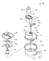
次に、図面を参照して本発明について説明するが、図中、同一の参照符号は、同一の部分を示している。いま図1を参照すると、加工装置100がモータハウジング102を有し、このモータハウジングは、装置100の機能を制御するコントロールパネル104を有するのが良い。コントロールパネル104は、装置の機能を選択するためのユーザインターフェイスとしてボタン、例えばボタン105〜110を有するのが良い。かかる機能としては、速度、加工時間、パルス、動作の作動形式及び電力が挙げられるが、これらには限定されない。コントロールパネル104は、視覚表示器又はインジケータ(図示せず)を更に有するのが良く、これらインジケータは、例えば、情報をユーザに提供する灯(例えば、LED)又はスクリーン(例えば、LCD)であるのが良い。ボウル112がモータハウジング102を覆って配置されるのが良い。ボウル蓋114がボウル112の口115を覆って配置されるのが良い。ボウル112は、取っ手又はハンドル116、加工材料のレベル(高さ位置)を指示する第1及び第2のレベルインジケータ118,119並びにボウル112がモータハウジング102及びボウル蓋114に固定されているかどうかを指示する第1及び第2のロックインジケータ120,121を有するのが良い。第3のロックインジケータ122がモータハウジング102に設けられるのが良く、この第3のロックインジケータは、第1のロックインジケータ120の一部分と整列すると、ボウル112がモータハウジング102に固定されていて、作業位置にあることをユーザに知らせることができるようになっている。第4のロックインジケータ123がボウル蓋114に設けられるのが良く、この第4のロックインジケータは、第2のロックインジケータ121の一部分と整列すると、ボウル蓋114がボウル112に固定されていて、作業位置にあることをユーザに知らせることができるようになっている。ボウル蓋114は、ユーザがボウル蓋114をボウル112上に正しく位置合わせするのを助けるハンドルロック124及びプッシュ128を受け入れるプッシャシュート126を更に有するのが良い。また、ボウル112をモータハウジング102に固定する第1のロック機構体(図示せず)及びボウル蓋114をボウル112に固定する第2のロック機構体(図示せず)が設けられるのが良い。
Next, the present invention will be described with reference to the drawings. In the drawings, the same reference numerals denote the same parts. Referring now to FIG. 1, the
装置100は、足部130を更に有するのが良く、足部は、装置100のための跡を残さないベースを提供することができる材料、例えばゴムで作られるのが良い。足部130は、更に、装置100が作動中、その作業面上で動くことがないように掴み機能を提供し、例えば吸引カップとなるよう形成されるのが良い。装置100が使用されていないときには電気コード210(図2)を巻き取ることができ又は使用中にはコード210を短くすることができるようコード巻き取り132が設けられるのが良い。変形例として、引っ込み可能なコード組立体(図示せず)を設けても良い。装飾アイテム、例えばロゴ134が追加の情報の提供及び/又は審美的目的のために設けられるのが良い。
The
図2は、加工装置100の第1の部分の分解組立て図である。モータハウジング102は、駆動軸線を備えたモータ、例えばモータ組立体202及び所望の機械的作用を生じさせる関連部品を更に有する。モータハウジング102は、ベース204及び本体206を有するのが良い。モータハウジング102は又、電気及び/又は電子モータ制御装置、例えば第1のプリント回路板208を収納するのが良く、この第1のプリント回路板は、この例では、電源コード210とモータ組立体202との間の電力を調節すると共にインターフェイスする。また、図1のコントロールパネル104は、ユーザインターフェイス及び動作要素、例えばメンブレンスイッチ表面212を有するのが良く、このメンブレンスイッチ表面は、動作マーク、例えばラベル、エンボス、エッチング又はその均等手段を有するのが良い。これらマークは、ユーザインターフェイスシステム、例えばボタン105〜110に寄与する個々の調整つまみ、ボタン及び/又はインジケータに対応するのが良い。所望ならば、種々の中間要素、例えばこの例ではコントロールプレート214及び灯カバー216に取り付けられたボタン及び灯を介して情報がユーザに行き来することができる。信号が種々の調整つまみ及びインジケータと例えば第2のプリント回路板218のような装置との間で流れるのが良く、この第2のプリント回路板は、この例では、第1のプリント回路板208に適した信号を生じさせ、所望の活動が起こるようにする。
FIG. 2 is an exploded view of the first part of the
モータハウジング102は又、少なくとも1つの吸引カップ、例えば足部130を採用するのが良く、かかる足部は、装置を作業面に固定するのに役立ち得る。モータハウジング102は、電源コード210をモータハウジング102内の固定位置に拘束することができる支持ハードウェア、例えばワイヤカバー220を更に有するのが良い。
The
例えばゴムで作られたモータ支持体222がモータ組立体202を収納するのが良く、このモータ組立体は、モータアクスル歯車224を回転させることができる。モータアクスル歯車224は、ドライブトレーン組立体と噛み合うのが良く、このドライブトレーン組立体は、少なくとも1つの歯車226(例えば、星形歯車)、歯車ブラケット228、歯車ブラケット228に取り付けられた第1のブッシュ230並びにブッシュマウント234に取り付け可能な第2及び第3のブッシュ232,233を有するのが良い。ブッシュ230,232,233は、例えば青銅で作られるのが良い。ドライブトレーン組立体は、駆動シャフト236を回転させることができ、この駆動シャフトは、モータハウジング102の外部に露出されるよう位置決め可能であり、この駆動シャフトは、駆動シャフトマウント238によって支持されるのが良い。
For example, a
ドライブトレーン組立体の1つ又は2つ以上の部品は、ベース歯車カバー240、頂部歯車ケース242及び第1のワッシャ244、例えばベークライトワッシャによって包囲され又は支持されるのが良い。モータハウジング102の種々のコンポーネントも又、密封リング246及びショックサークル又は緩衝輪248によって支持されると共に保護されるのが良い。
One or more parts of the drive train assembly may be surrounded or supported by a
また、オプションとしてのトリム要素、例えば装飾カバー250、装飾リング252及び他の装飾アイテム、例えばロゴ134が更に設けられるのが良い。装置100は、例えば種々の組立て及び締結方式を用いることにより経済的に且つ確実に製造可能であり、かかる組立て及び締結方式は、ハードウェア、例えば締結具254及びねじ256〜264を用いるのが良い。例えばユーザに見え又は屑片の影響を受けやすい少なくとも何本かのねじは、ねじカバー265によって覆われるのが良い。
In addition, optional trim elements, such as
モータハウジング102は、装置が正しく構成された場合にのみ装置が作動することができるようにするインターロックシステムを更に収納するのが良い。典型的には、インターロックシステムは、作動に必要なアイテムの存否を検出する。インターロックシステムは、電力がモータ組立体202に流れるのを制限することができるモータ係合装置、例えばマイクロスイッチ266を有するのが良い。変形例として、ドライブトレーン組立体を通る機械的エネルギーの流れを妨げるための機構体、例えばクラッチをモータ係合装置のために用いても良い。
The
インターロックシステム内のマイクロスイッチ266をスイッチレバー268により作動させることができ、このスイッチレバーは、支点バー270によって支持されるのが良い。スイッチレバー268は、アクションバー272とインターフェイスすることができ、アクションバーは、通常、ばねマウント267によって支持された第1のばね274によってアクションバー272に加えられる圧力の結果としてデフォルト伸長位置に維持されるのが良い。アクションバー272は、滑動して第1のレバー280に連結されているピン278に当たることができ、ピン278と第1のレバー280の両方は、駆動シャフト236内に収納されるのが良い。第1のレバー280は、駆動係合装置であるのが良く、この第1のレバーは、駆動シャフト236内に配置されるのが良い。これらアイテムは、この場合、デフォルト伸長位置と引っ込み位置との間で共通の運動を伝えることができ、引っ込み位置は、第1のばね274によって加えられる圧力に抗してのみ達成可能である。第1のレバー280は、駆動シャフト236の中心を通ってモータハウジング102の外部とインターフェイスすることができる。この構成により、第1のレバー280は、その伸長又は引っ込み位置をマイクロスイッチ266に伝えることができる。インターロックシステムは、装置100の作動に必要と考えられるアイテムの存在により第1のレバー280がその引っ込み位置を取り、それにより機械を作動させることができるよう構成されているのが良い。
The
駆動シャフト236及びインターロック機構体の適正な向きは、追加のハードウェア、例えば締結カラー282、追加のワッシャ284,285及び固定ガスケット286によって維持されるのが良い。また、第1のレバー280が検出されるようになったアイテムの適正な取り付けによってのみ引っ込められるようにするための駆動シャフトプロテクタ288が設けられるのが良い。図5を参照して駆動シャフトプロテクタ288について以下に詳細に説明する。
Proper orientation of the
次に図3を参照すると、装置100の第2の部分が示されている。モータハウジング102(図1及び図2)は、容器組立体300とインターフェイスすることができ、この容器組立体は、ボウル112及びボウル蓋114を有している。ボウル112は、取っ手又はハンドル116を有するのが良く、このハンドルは、ボウルハンドルカバー302を更に有するのが良い。ボウル112は駆動シャフト236(図2)に被さることができるよう構成されているのが良い。ボウル蓋114は、蓋シャフト303を有するのが良く、この蓋シャフトは、ボウル112、ボウル蓋114及び作動に必要な任意他のアイテムの適正な取り付けの結果としてのみ第1のレバー280(図2)を引っ込める第2のレバー304を収容するのが良い。
Referring now to FIG. 3, a second portion of the
装置100は、ブレードツール306,308,310を更に有するのが良く、これらブレードツールは、ボウル112の内部で駆動シャフト236に取り付けた状態で位置決め可能であり、これらブレードツールをモータハウジング102によって生じる機械的作用の結果として回転させることができる。ブレードツール306,308,310は、再構成可能であるのが良く、ユーザは、装置によって加工されるべき材料の性状及び意図した結果に基づいてブレードツールを選択することができる。ブレードツール306,308,310は、切り刻みブレード306、ドウ(生地用)ブレード308及びカッターディスク310を含むのが良い。ブレードツール306,308,310のうちの1つ又は2つ以上をブレードシャフト312に固定することができ、ブレードシャフト312は、ボウル112内に挿入されて駆動シャフト236とインターフェイスされるのが良い。これらアイテムのうちの幾つかは、追加のハードウェア、例えばフォックスキャップ(fox
cap)314によって安定化されるのが良い。
The
cap) 314 may be stabilized.
ブレードシャフト312は、機械的回転を挿入状態のブレードツールに伝えることができる活動領域のうちの1つ又は2つ以上を有するのが良い。ブレードシャフト312は、機械が作動しているとき又は装置100が使用されていないときに保管又はしまい込みのためにブレードツールを回転させないでこれを保持する非活動領域の内の1つ又は2つ以上を更に有するのが良い。この形態により、使用されないブレードのための外部保管又はしまい込み手段を設ける必要がなくなり又は使用されていないブレードをなくすことがない。加うるに、ボウル蓋114がボウル112に取り付けられ、ブレードツール306,308,310がボウル内に収納された状態で装置100を保管する場合、ほこりやデブリの堆積を避けることができる。
The
ユーザは、装置100の作動中に追加の材料を容器組立体内に加えることができる。プッシャシュート126が追加の材料及びプッシャ128を受け入れるようボウル蓋114に設けられるのが良い。また、ユーザによる材料の挿入を助けるために、新たに追加される材料の導入及び加工を完了させるためにユーザがプッシャシュート126内に挿入することができるツールとして使用される外側プッシャ316を設けるのが良い。
The user can add additional material into the container assembly during operation of the
外側プッシュ316の取り付けにより、装置の作動が保証されるのが良く、しかも、外側プッシャは、ユーザが回転中のブレード組立体との直接的な接触が起こることから保護することができる。したがって、インターロックが外側プッシャ316の取り付けをモニタすると共にこれを必要とするようにすることが望ましい場合がある。ボウル蓋114は、係合センサ318を有するのが良く、この係合センサは、ブラケット320によって固定されると共に第2のばね322によって及ぼされる機械的圧力によってデフォルト伸長位置に維持されるのが良い。係合センサ318は、外側プッシャ316の適正な取り付けにより係合センサ318が外側プッシャ316の一部として設けられたプッシャ係合部分602(図6)及びオプションとしてのプッシャ係合部分用ランプ又は傾斜部604(図6)と相互作用することができるよう構成されているのが良い。この作用により、係合センサ318は、第2のばね322の力に抗してその引っ込み位置を取る。係合センサ318は又、第2のレバー304と相互作用し、この第2のレバーは、蓋シャフト303内に設けられた蓋ばね、例えば第3のばね324によって加えられる力によりデフォルト位置に同様に維持される。その結果、係合センサ318及び第2のレバー304の運動は、外側プッシャ316の取り付けに関連づけられるのが良い。係合センサ318及び蓋ばね(例えば、第3のばね324)の運動により、蓋係合装置(例えば、第2のレバー304)を押し下げることができ、それにより駆動係合装置(例えば、第1のレバー280)を引っ込み、作業又は動作可能な位置に動かしてこれを稼働させることができる。
Installation of the
外側プッシャ316をプッシャシュート126内に挿入し、ボウル蓋114をボウル112に固定し、そしてボウル112をモータハウジング102に固定すると、装置100は、作動可能又は作業位置になっているのが良い。この位置では、蓋係合装置(例えば、第2のレバー304)、駆動係合装置(例えば、第1のレバー280)及び駆動シャフト236は、軸方向に互いに整列することができる。駆動係合装置(例えば、第1のレバー280)を引っ込み位置に動かすことができる。
With the
これら要素のうちの1つ又は2つ以上は、係合センサ318及びブラケット320を覆うシェルタ326によって保護されるのが良い。また、係合センサ318の一部分がプッシャ係合部分602以外の何らかの物体による係合センサ318の作動を回避するようシュート126に取り付けられている蓋シャフト案内328内に突き出るのが良い。プッシャ係合部分602は、例えばレールとして蓋シャフト案内328を通って動くのが良い。
One or more of these elements may be protected by a
第2のレバー304は、第1のレバー280と相互作用するよう位置決めされるのが良い。この形態により、インターロック機構体は、重要な要素、例えばボウル112、ブレードシャフト312、ボウル蓋114及び外側プッシャ316のうちの1つ又は2つ以上の適正な取り付けの結果としてのみ機械が作動することができるようにする。
The
外側プッシャ316は、内側シュート606(図6)を有するのが良く、この内側シュートは、追加の材料を受け入れることができると共に内側プッシャ330を受け入れることができ、この内側プッシャは、内側シュート606内への材料の挿入を完了させるツールとして使用されるのが良い。内側プッシャ330は、装置の作動中にユーザが流体、例えば水を容器組立体内に注ぎ込むことができるようにする液体取り入れポート332を有するのが良く、この場合、部品を取り外す必要がなく、しかも、追加の流体が回転中のブレード組立体との接触時に機械からはね出る恐れが生じないようになっている。内側プッシャ330と外側プッシャ316は、プッシャロック機構体334,336によって互いに接合されるのが良く、その結果、複数個のプッシャを単一組立体、例えば図1に示されているプッシャ128として作動させることができるようになっている。
The
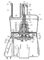
図4は、装置100の断面図であり、図1〜図3の要素は、これらの組立て位置で示されている。理解されるべきこととして、図示の構成では、装置100は、インターロックを働かせるよう作動位置にある。
FIG. 4 is a cross-sectional view of the
図5は、装置100用の駆動シャフトプロテクタ288を示している。駆動シャフトプロテクタ288は、第1のレバー280の端部に被さる本体505を有している。第1のレバー280(図2)の端部は、本体内に突き出て穴515のところでこれに接近可能であるのが良く、したがって、外側プッシャ316をシュート126内に挿入すると、第2のレバー304(図3)が第1のレバー280に接触してこれを押し下げることができるようになっている。オプションとして設けられたスロット510により、第1のレバー280の端部の側部が駆動シャフトプロテクタ288の内部で視認でき、それにより、組立て中、駆動シャフトプロテクタ288の適正な配置が可能である。
FIG. 5 shows a
図6は、外側プッシャ316を示しており、この外側プッシャは、プッシャロック機構体334の上述の部分、プッシャ係合部分602、オプションとしてのプッシャ係合部分ランプ604及び内側シュート606を有している。外側プッシャ316は、傾斜部分610を備えた底面608を更に有している。傾斜部分610の角度は、駆動軸線に対して非垂直であるのが良い。傾斜部分610の角度の非限定的な例は、水平軸線に対して30°〜40°又は駆動軸線に対して50°〜60°であるのが良い。傾斜部分610は、これが底面608の残部に出会う角度、例えば30°をなしていても良い。装置100の作動中、外側プッシャ316をプッシャシュート126内に挿入すると、傾斜部分610は、外側プッシャ316又はプッシャシュート126の側部にくっついている場合のある材料を使用中のブレードツール(例えば、ブレードツール306,308,310のうちの任意のもの)中に押し込み、そしてボウル112内に投入する作用効果を生じさせる。
加工装置の実施形態は、他の機能を有することができる。例えば、温度制御システム、例えば氷入れ又は加熱装置を設けることができる。かかる温度制御システムは、食品の維持に役立ち得る。
FIG. 6 shows an
Embodiments of the processing apparatus can have other functions. For example, a temperature control system, such as an ice container or a heating device can be provided. Such a temperature control system can help maintain food.
例えば泡立ち又は圧力増大の場合にオーバーフロースイッチが機械を作動停止させるのが良い。一実施形態では、このスイッチは、係合センサ318に取り付けられるのが良い。オーバーフロー注ぎ口が容器の容量を超えた材料の出口経路を方向づけることができる。実施形態は、自動クリーニング機能を更に備えるのが良く、かかる自動クリーニング機能により、ユーザは、容器組立体に水又は他の洗浄材料を意図的に過剰充填しながら機械を作動させることができ、それにより、かかる水又は他の洗浄材料は、オーバーフロー注ぎ口を通って出て、それにより、通常機械が加工している材料と相互作用している装置の部分がクリーニングされる。場合によっては自動クリーニングサイクル後に用いられる自動乾燥機能は、例えば遠心力の作用、空気流、熱又は装置の作動に関与する類似の活動によって、残存している水又は洗浄材料の大部分を機械からなくし又は追い出すことができる。
For example, an overflow switch may shut down the machine in the event of bubbling or increased pressure. In one embodiment, this switch may be attached to the
空気取り入れ制御ポートが加工中の材料の結果に影響を及ぼす場合がある。これは、例えば泡立てクリーム、シェービングクリームを作る際に特定の結果を達成するため若しくはドウ又はバターをコンディショングして次に焼かれる又は調理される製品のふわふわさを制御するために使用可能である。 The air intake control port may affect the result of the material being processed. This can be used, for example, to achieve specific results in making whipping creams, shaving creams or to condition the dough or butter to control the fluffiness of products that are subsequently baked or cooked .
装置を空気取り入れと関連して作動させ、空気が収容状態の材料を押し退けて制御された量の材料が意図的にオーバーフロー注ぎ口を通って排出されるようにする給仕又は小分けモードを設けることができる。これは、例えば、装置内の材料を個々の消費のために分配することができるようにするために使用できる。 Operate the device in conjunction with air intake and provide a serving or subdivision mode in which the air pushes away the contained material so that a controlled amount of material is intentionally discharged through the overflow spout. it can. This can be used, for example, to allow the material in the device to be dispensed for individual consumption.
実施形態は、容易な再構成及び識別のために種々の部品、例えばブレードツール306,308,310の色分け手段を有する。本発明の追加の実施形態は、モータハウジング102が装置の頂部に設けられて例えば台所カウンタ又はキャビネットの下から吊り下げ状態で取り付けられるよう逆さま設計となっているのが良い。
Embodiments include color coding means for various parts, such as
別の実施形態は、アイスクリーム又は他の冷菓を作るためのプログラムモードであるのが良いアイスクリームサイクルを有する。電源コードアダプタを設けるのが良く、この電源コードアダプタは、例えば、ユニット全体を通常のフリーザの内部に配置することができるよう特に平べったい領域を有するのが良く、したがって、電源コードの平べったい領域を既存のフリーザドア用シールガスケットを横切って位置決めしてフリーザドアが閉じることができ、そしてフリーザが通常通り作動するようになっているのが良い。 Another embodiment has an ice cream cycle that may be in a program mode for making ice cream or other frozen desserts. A power cord adapter may be provided, and this power cord adapter may have a particularly flat area, for example, so that the entire unit can be placed inside a normal freezer. The free area should be positioned across the existing freezer door seal gasket to close the freezer door, and the freezer should operate normally.
実施形態は、制御アルゴリズムの幾つかのモードの一部として用いられる加工済み材料の温度の測定温度センサ(例えば、温度計、熱電対又はサーミスタ)を有するのが良い。温度センサは、上述の温度制御システムと併用可能であり又は制御の決定を行う際にリアルタイム温度を考慮する必要のあるプロセス及びレシピ用に使用できる。 Embodiments may include a temperature sensor (eg, thermometer, thermocouple, or thermistor) that measures the temperature of the processed material used as part of some modes of the control algorithm. The temperature sensor can be used in conjunction with the temperature control system described above or can be used for processes and recipes that need to consider real-time temperature when making control decisions.
加工されるべき材料は「食品」として説明されている場合が多いが、他の材料を加工することができるということは理解されるべきである。さらに、装置100の種々のアイテムを形成する本明細書において説明した材料は、本発明を限定するものではなく、例として挙げられているに過ぎない。
The material to be processed is often described as “food”, but it should be understood that other materials can be processed. Further, the materials described herein that form the various items of the
上述の説明及び図面に記載されたプロセス及び装置は、本明細書において説明した実施形態の目的、特徴及び利点を達成するために使用されたり構成されたりすることが可能な方法及び装置のうちのほんの幾つかの例を示しているに過ぎない。かくして、これらプロセス及び方法は、実施形態に関する上述の説明によって限定されるものと理解されてはならず、特許請求の範囲の記載によってのみ限定される。本発明の範囲内において或る請求項の内容又は特徴を任意他の請求項の内容又は特徴と組み合わせることができる。 The processes and apparatus described in the foregoing description and drawings are among the methods and apparatus that can be used or configured to achieve the objects, features, and advantages of the embodiments described herein. There are only a few examples. Thus, these processes and methods should not be construed as limited by the foregoing description of the embodiments, but only by the claims. Within the scope of the invention, the content or features of one claim may be combined with the content or features of any other claim.
本発明の多くの特徴及び利点は、詳細な説明から明らかであり、かくして、本発明の真の精神及び範囲に属する本発明のかかる全ての特徴及び利点を包含することが特許請求の範囲によって意図されている。さらに、多くの改造例及び変形例が当業者に容易に明らかなので、本発明を図示すると共に説明した構成及び作用そのものに限定するものではなく、したがって、適当な改造例及び均等例は全て、本発明の範囲に含まれるものである。 Many features and advantages of the invention will be apparent from the detailed description, and thus are intended by the appended claims to cover all such features and advantages of the invention which fall within the true spirit and scope of the invention. Has been. Further, since many modifications and variations will be readily apparent to those skilled in the art, the invention is not limited to the exact construction and operation illustrated and described, and accordingly, all suitable modifications and equivalents are It is included in the scope of the invention.
100 加工装置
102 モータハウジング
104 コントロールパネル
105〜110 ボタン
112 ボウル
114 ボウル蓋
115 ボウル口
116 ハンドル
118,119 レベルインジケータ
121,123 ロックインジケータ
124 ハンドルロック
126 プッシャシュート
128 プッシャ
202 モータ組立体
236 駆動シャフト
266 モータ係合部又はマイクロスイッチ
280 駆動係合装置又は第1のレバー
288 駆動シャフトプロテクタ
300 容器組立体
303 蓋シャフト
304 蓋係合装置又は第2のレバー
310 ブレードツール
316 外側プッシャ
318 係合センサ
DESCRIPTION OF
Claims (45)
ハウジングを有し、前記ハウジングは、モータと、前記ハウジングから延びる駆動シャフトとを有し、前記駆動シャフトは、モータによって駆動軸線回りに回転可能であり、前記駆動シャフトは、前記駆動軸線に沿って伸長位置と引っ込み位置との間で動くことができる駆動係合装置を有し、
口を備えたボウルを有し、前記ボウルは、前記ハウジングに対して着脱可能に取り付け可能であり、前記駆動シャフトは、前記ボウルが作業位置で前記ハウジングに固定されると、前記ボウル内に延び、
前記ボウルの前記口を覆って着脱可能に取り付け可能であるボウル蓋を有し、前記ボウル蓋は、前記ボウルを覆って取り付けられると、作業位置にあり、前記ボウル蓋は、シュートを有し、
前記ボウル蓋及び前記シュートに取り付けられた蓋シャフトを有し、前記蓋シャフトは、前記ボウル及び前記ボウル蓋が前記作業位置にあるときに前記駆動シャフトと軸方向に整列するよう構成された蓋係合装置を有し、
前記シュートを通って動くことができるプッシャを有し、前記プッシャは、前記ボウル及び前記ボウル蓋が前記作業位置にあるとき、前記蓋係合装置が前記駆動係合装置を前記引っ込み位置に動かすようにするためのプッシャ係合部分を有し、
前記駆動係合装置が前記引っ込み位置にあるとき、前記駆動シャフトは、前記モータによって回転可能である、加工装置。 A processing device,
A housing having a motor and a drive shaft extending from the housing, the drive shaft being rotatable around a drive axis by the motor, the drive shaft being along the drive axis A drive engagement device capable of moving between an extended position and a retracted position;
A bowl with a mouth, the bowl being detachably attachable to the housing, and the drive shaft extending into the bowl when the bowl is secured to the housing in a working position. ,
A bowl lid that is removably attachable over the mouth of the bowl; the bowl lid is in a working position when attached over the bowl; the bowl lid has a chute;
A lid shaft attached to the bowl lid and the chute, the lid shaft configured to be axially aligned with the drive shaft when the bowl and the bowl lid are in the working position; Have a combined device,
A pusher movable through the chute, wherein the pusher causes the lid engagement device to move the drive engagement device to the retracted position when the bowl and the bowl lid are in the working position. A pusher engaging portion for
The processing device, wherein the drive shaft is rotatable by the motor when the drive engagement device is in the retracted position.
ハウジングを用意するステップを有し、前記ハウジングは、モータと、前記ハウジングから延びる駆動シャフトとを有し、前記駆動シャフトは、モータによって駆動軸線回りに回転可能であり、前記駆動シャフトは、前記駆動軸線に沿って伸長位置と引っ込み位置との間で動くことができる駆動係合装置を有し、
口を備えたボウルを用意するステップを有し、前記ボウルは、前記ハウジングに対して着脱可能に取り付け可能であり、前記駆動シャフトは、前記ボウルが作業位置で前記ハウジングに固定されると、前記ボウル内に延び、
前記ボウルの前記口を覆って着脱可能に取り付け可能であるボウル蓋を用意するステップを有し、前記ボウル蓋は、前記ボウルを覆って取り付けられると、作業位置にあり、前記ボウル蓋は、シュートを有し、
前記ボウル蓋及び前記シュートに取り付けられた蓋シャフトを用意するステップを有し、前記蓋シャフトは、前記ボウル及び前記ボウル蓋が前記作業位置にあるときに前記駆動シャフトと軸方向に整列するよう構成された蓋係合装置を有し、
前記シュートを通って動くことができるプッシャを用意するステップを有し、前記プッシャは、前記ボウル及び前記ボウル蓋が前記作業位置にあるとき、前記蓋係合装置が前記駆動係合装置を前記引っ込み位置に動かすようにするためのプッシャ係合部分を有し、
前記駆動係合装置が前記引っ込み位置にあるとき、前記駆動シャフトは、前記モータによって回転可能である、方法。 A method of assembling a processing apparatus,
Providing a housing, the housing having a motor and a drive shaft extending from the housing, the drive shaft being rotatable about a drive axis by the motor, the drive shaft being the drive A drive engagement device capable of moving between an extended position and a retracted position along an axis;
Providing a bowl with a mouth, wherein the bowl is removably attachable to the housing, and the drive shaft is secured to the housing in the working position when the bowl is secured to the housing; Extend into the bowl,
Providing a bowl lid detachably attachable over the mouth of the bowl, wherein the bowl lid is in a working position when attached over the bowl, and the bowl lid is chute Have
Providing a lid shaft attached to the bowl lid and the chute, the lid shaft configured to be axially aligned with the drive shaft when the bowl and the bowl lid are in the working position; A lid engaging device,
Providing a pusher capable of moving through the chute, wherein the pusher retracts the drive engagement device when the bowl and the bowl lid are in the working position. A pusher engaging portion for moving to a position,
The method, wherein the drive shaft is rotatable by the motor when the drive engagement device is in the retracted position.
ハウジングを有し、前記ハウジングは、モータと、前記ハウジングから延びる駆動シャフトとを有し、前記駆動シャフトは、モータによって駆動軸線回りに回転可能であり、前記駆動シャフトは、前記駆動軸線に沿って伸長位置と引っ込み位置との間で動くことができる駆動係合手段を有し、
口を含む収納手段を有し、前記収納手段は、前記ハウジングに対して着脱可能に取り付け可能であり、前記駆動シャフトは、前記収納手段が作業位置で前記ハウジングに固定されると、前記収納手段内に延び、
前記収納手段の前記口を覆って着脱可能に取り付け可能である覆い手段を有し、前記覆い手段は、前記収納手段を覆って取り付けられると、作業位置にあり、前記覆い手段は、シュート機能を発揮する手段を有し、
前記覆い手段及び前記シュート機能発揮手段に取り付けられた蓋シャフトを有し、前記蓋シャフトは、前記収納手段及び前記覆い手段が前記作業位置にあるときに前記駆動シャフトと軸方向に整列するよう構成された蓋係合手段を有し、
前記シュート機能発揮手段を通って動くことができる押圧手段を有し、前記押圧手段は、前記収納手段及び前記覆い手段が前記作業位置にあるとき、前記蓋係合手段が前記駆動係合手段を前記引っ込み位置に動かすようにするためのプッシャ係合手段を有し、
前記駆動係合手段が前記引っ込み位置にあるとき、前記駆動シャフトは、前記モータによって回転可能である、加工装置。 A processing device,
A housing having a motor and a drive shaft extending from the housing, the drive shaft being rotatable about a drive axis by the motor, the drive shaft being along the drive axis Having drive engagement means movable between an extended position and a retracted position;
The storage means includes a mouth, the storage means is detachably attachable to the housing, and the drive shaft is configured such that when the storage means is fixed to the housing at a working position, the storage means Extending in,
Covering means that covers the mouth of the storage means and is detachably attachable. The cover means is in a working position when it is attached to cover the storage means, and the cover means has a chute function. Has a means to exert,
A lid shaft attached to the covering means and the chute function exhibiting means, wherein the lid shaft is axially aligned with the drive shaft when the storage means and the covering means are in the working position; A lid engaging means,
And pressing means that can move through the chute function exhibiting means. The pressing means is configured such that when the storage means and the covering means are at the working position, the lid engaging means Pusher engaging means for moving to the retracted position;
The processing apparatus, wherein the drive shaft is rotatable by the motor when the drive engagement means is in the retracted position.
Applications Claiming Priority (2)
| Application Number | Priority Date | Filing Date | Title |
|---|---|---|---|
| US24044009P | 2009-09-08 | 2009-09-08 | |
| US12/870,346 US8262005B2 (en) | 2009-09-08 | 2010-08-27 | Processing apparatus and method |
Publications (2)
| Publication Number | Publication Date |
|---|---|
| JP2011056269A true JP2011056269A (en) | 2011-03-24 |
| JP2011056269A5 JP2011056269A5 (en) | 2013-10-17 |
Family
ID=43037404
Family Applications (1)
| Application Number | Title | Priority Date | Filing Date |
|---|---|---|---|
| JP2010217835A Pending JP2011056269A (en) | 2009-09-08 | 2010-09-08 | Processing apparatus and method of assembling thereof |
Country Status (7)
| Country | Link |
|---|---|
| US (1) | US8262005B2 (en) |
| JP (1) | JP2011056269A (en) |
| CN (1) | CN102008117B (en) |
| BR (1) | BRPI1010416A2 (en) |
| CA (1) | CA2714522A1 (en) |
| GB (1) | GB2473342A (en) |
| MX (1) | MX2010009830A (en) |
Families Citing this family (24)
| Publication number | Priority date | Publication date | Assignee | Title |
|---|---|---|---|---|
| IT1394938B1 (en) * | 2009-01-12 | 2012-07-27 | Valmar Global Vse Za Sladoled D O O | MACHINE FOR THE PRODUCTION OF ICE CREAM AND THE LIKE |
| US8814334B2 (en) * | 2012-01-23 | 2014-08-26 | Seiko Epson Corporation | Liquid accommodating container and liquid ejecting apparatus |
| US20130233952A1 (en) * | 2012-03-08 | 2013-09-12 | Hamilton Beach Brands, Inc. | Kitchen Appliance for Processing Foodstuff and Method of Operating Same |
| TWI568389B (en) * | 2012-04-04 | 2017-02-01 | 佛維爾克控股公司 | Kitchen machine |
| WO2014144638A1 (en) | 2013-03-15 | 2014-09-18 | Vita-Mix Corporation | Powered blending container |
| US9198540B2 (en) * | 2013-08-02 | 2015-12-01 | Hamilton Beach Brands, Inc. | Food processor with locking bail handle |
| US9326640B2 (en) * | 2013-08-07 | 2016-05-03 | Conair Corporation | Food processor feed tube assembly |
| CN105934159A (en) * | 2013-11-29 | 2016-09-07 | 布瑞威利私人有限公司 | Improved base driven appliance and attachments |
| EP3119251A4 (en) | 2014-03-20 | 2017-11-29 | Vita-Mix Management Corporation | Container/lid/blender interlock |
| BR302014001652S1 (en) * | 2014-03-26 | 2015-06-09 | Electrolux Appliances AB | Ornamental configuration applied in food processor |
| US9049967B1 (en) | 2014-08-08 | 2015-06-09 | Euro-Pro Operating Llc | Food processing apparatus and method |
| WO2016144393A1 (en) | 2015-03-06 | 2016-09-15 | Sharkninja Operating Llc | Food processor system |
| US20160270597A1 (en) * | 2015-03-16 | 2016-09-22 | Jonathon Walczak | Electronic herb grinder |
| JP6942638B2 (en) | 2015-06-08 | 2021-09-29 | シャークニンジャ オペレーティング エルエルシー | Food processing equipment and methods |
| GB2547683B (en) * | 2016-02-25 | 2022-07-13 | Kenwood Ltd | Kitchen appliance |
| USD830124S1 (en) | 2016-03-04 | 2018-10-09 | Vita-Mix Management Corporation | Container |
| US10695935B2 (en) | 2016-08-11 | 2020-06-30 | Conair Corporation | Slicing disc assembly for food processor |
| USD839670S1 (en) | 2017-02-16 | 2019-02-05 | Vita-Mix Management Corporation | Blending container |
| US11013371B2 (en) * | 2017-03-10 | 2021-05-25 | Vita-Mix Management Corporation | Wireless food processor discs |
| USD842566S1 (en) | 2017-06-15 | 2019-03-05 | Vita-Mix Management Corporation | Container scraper |
| USD853177S1 (en) * | 2017-12-18 | 2019-07-09 | Whirlpool Corporation | Food processor |
| US11877696B2 (en) * | 2019-12-19 | 2024-01-23 | Vita-Mix Management Corporation | Food processor |
| CN113633198B (en) * | 2020-05-11 | 2022-11-22 | 广东美的生活电器制造有限公司 | Food processor |
| KR20220037604A (en) * | 2020-09-18 | 2022-03-25 | 쿠쿠전자 주식회사 | Mixer having two way rotatable knife |
Citations (4)
| Publication number | Priority date | Publication date | Assignee | Title |
|---|---|---|---|---|
| JPS573370B2 (en) * | 1976-12-22 | 1982-01-21 | ||
| JPS60165928A (en) * | 1984-02-08 | 1985-08-29 | 松下電器産業株式会社 | Sefety apparatus of cooker |
| JPH04103843U (en) * | 1991-01-25 | 1992-09-08 | 株式会社国盛化学 | small electric cooking device |
| JP2003039384A (en) * | 2001-05-02 | 2003-02-13 | Hameur Sa | Mechanical safety device for food processor |
Family Cites Families (51)
| Publication number | Priority date | Publication date | Assignee | Title |
|---|---|---|---|---|
| DD99094A1 (en) | 1972-06-29 | 1973-07-20 | ||
| US4143824A (en) * | 1977-08-29 | 1979-03-13 | Sanyei Corporation | Vessel and blades for food processor, or the like |
| US4199268A (en) * | 1978-10-18 | 1980-04-22 | Dynamics Corporation Of America | Food processor |
| US4216917A (en) * | 1978-11-13 | 1980-08-12 | Cuisinarts, Inc. | Safety interlock for the food pusher in a food processor |
| US4226373A (en) * | 1979-03-05 | 1980-10-07 | Wilson Research & Development, Inc. | Feed tube protector for a food processor |
| US4316584A (en) * | 1979-04-12 | 1982-02-23 | Dynamics Corporation Of America | Liquid dispenser for food processor |
| US4741482A (en) * | 1979-08-29 | 1988-05-03 | Robot-Coupe S.A. | Magnetic safety switch device for food processor |
| US4371118A (en) * | 1980-06-02 | 1983-02-01 | Cuisinarts, Inc. | Magnetic safety interlock method and apparatus for food processor |
| US4629131A (en) * | 1981-02-25 | 1986-12-16 | Cuisinarts, Inc. | Magnetic safety interlock for a food processor utilizing vertically oriented, quadrant coded magnets |
| US4396159A (en) * | 1981-02-25 | 1983-08-02 | Cuisinarts, Inc. | Protective guide structure for preventing inadvertent actuation of a food processor with a tilted cover |
| AU1181083A (en) * | 1982-03-08 | 1983-09-15 | Seirindo International Co. Ltd. | Food processor |
| US4471915A (en) * | 1982-08-17 | 1984-09-18 | Scovill Inc. | Food processor having enlarged feed tube with safety guard |
| US4506836A (en) * | 1982-12-20 | 1985-03-26 | Cuisinarts Research & Development, Inc. | Dual cover and feed tube protector actuation apparatus for a food processor |
| DE3335139C2 (en) | 1983-09-28 | 1985-11-14 | Geka-Werk Reinhold Klein KG, 3573 Gemünden | Food processor with a safety switch |
| EP0127050A3 (en) | 1983-05-28 | 1985-10-16 | Geka-Werk Reinhold Klein KG | Kitchen machine |
| US4512522A (en) * | 1983-06-02 | 1985-04-23 | Cuisinarts, Inc. | Single vertical motion feedtube protector and actuator for a food processor |
| US4614306A (en) * | 1984-10-10 | 1986-09-30 | Kitchenaid, Inc. | Pivoting protector for food processor feed tube |
| DE4128456A1 (en) | 1991-08-28 | 1993-03-04 | Braun Ag | CRUSHING DEVICE FOR AN ELECTRICAL KITCHEN MACHINE |
| US5495795A (en) * | 1991-12-20 | 1996-03-05 | Trillium Health Products, Inc. | Juice extractors |
| US5417152A (en) * | 1991-12-20 | 1995-05-23 | Harrison; Robert G. | Speed controls |
| FR2690611B1 (en) * | 1992-04-30 | 1996-02-02 | Moulinex Sa | HOUSEHOLD APPLIANCE SUCH AS A MIXER EQUIPPED WITH A SECURITY DEVICE. |
| JP2758140B2 (en) * | 1994-08-10 | 1998-05-28 | 相川鉄工株式会社 | How to attach / detach refiner disks |
| FR2729588B1 (en) * | 1995-01-24 | 1997-06-13 | Moulinex Sa | HOUSEHOLD APPLIANCE WITH ROTARY KNIFE, SUCH AS A MINCER |
| FR2730624B1 (en) * | 1995-02-16 | 1998-06-19 | Moulinex Sa | ELECTRIC HAND MIXER |
| US6027242A (en) * | 1995-09-01 | 2000-02-22 | 24Th & Dean | Food preparation blender with mixing blades oscillating between larger and smaller volumes |
| FR2756477B1 (en) * | 1996-12-04 | 2000-06-02 | Moulinex Sa | HOUSEHOLD APPLIANCE WITH ROTARY KNIFE FOR THE PREPARATION OF FOOD COMPRISING A SAFETY DEVICE |
| US5735193A (en) * | 1997-06-27 | 1998-04-07 | Chang; Po Feng | Food processor |
| FR2765467B1 (en) * | 1997-07-04 | 2000-01-28 | Moulinex Sa | HOUSEHOLD APPLIANCE FOR THE PROCESSING OF FOODS COMPRISING A SAFETY DEVICE |
| FR2773977B1 (en) * | 1998-01-23 | 2000-12-22 | Moulinex Sa | HOUSEHOLD MIXER |
| US5921485A (en) * | 1998-04-10 | 1999-07-13 | Hp Intellectual Corp. | Food processor |
| US6254019B1 (en) * | 1998-09-16 | 2001-07-03 | John Alexander Galbreath | Food processor |
| FR2801486B1 (en) * | 1999-11-25 | 2002-03-01 | Robot Coupe Sa | SECURITY KEYBOARD FOR KITCHEN ROBOT |
| CN2405526Y (en) * | 1999-12-07 | 2000-11-15 | 大舜实业股份有限公司 | Food-cooking machine with safety protection function |
| US6510784B1 (en) * | 2000-04-18 | 2003-01-28 | Robot Coupe | Mechanical safety device for food processing appliance |
| EP1229814A1 (en) * | 2000-08-31 | 2002-08-14 | Koninklijke Philips Electronics N.V. | Kitchen appliance having a removable container and protection means |
| WO2002028245A1 (en) * | 2000-10-05 | 2002-04-11 | Koninklijke Philips Electronics N.V. | Kitchen appliance having a processing container and having a container for processing tools |
| FR2818525B1 (en) * | 2000-12-27 | 2003-09-05 | Seb Sa | HOUSEHOLD APPLIANCE FOR FOOD PREPARATION COMPRISING A SIMPLIFIED LOCKING DEVICE OF A LID ON A CONTAINER |
| US6609821B2 (en) * | 2001-04-13 | 2003-08-26 | Sunbeam Products, Inc. | Blender base with food processor capabilities |
| US6397735B1 (en) * | 2001-08-21 | 2002-06-04 | Kayue Electric Company Limited | Electronic food processor |
| US6532863B1 (en) * | 2002-09-03 | 2003-03-18 | Ming-Tsung Lee | Food processor |
| US6986475B2 (en) * | 2003-06-10 | 2006-01-17 | Conair Corporation | Cover for food processor |
| US6907819B2 (en) * | 2003-07-01 | 2005-06-21 | Conair Corporation | Flip ramp mechanical interlock for appliance |
| AU2003304417A1 (en) | 2003-08-13 | 2005-03-07 | Nuc Electronics Co., Ltd. | Juicer with a safety device |
| US7252252B2 (en) | 2004-02-18 | 2007-08-07 | Hamilton Beach/Proctor-Silex, Inc. | Food processor lid |
| US7229036B2 (en) * | 2004-02-18 | 2007-06-12 | Hamilton Beach/Proctor Silex, Inc. | Food processing appliance with indicator |
| US7028930B2 (en) * | 2004-02-19 | 2006-04-18 | Hamilton Beach/Proctor-Silex, Inc. | Kitchen appliance with a safety interlock |
| US20060201341A1 (en) * | 2004-06-28 | 2006-09-14 | Kernan Colin M | Flip ramp mechanical interlock for appliance |
| JP4779681B2 (en) * | 2006-02-07 | 2011-09-28 | パナソニック株式会社 | Touch panel |
| US7708215B2 (en) * | 2006-11-14 | 2010-05-04 | Wang Dong-Lei | Food processor cover |
| US7461801B2 (en) * | 2007-01-05 | 2008-12-09 | Lyu Jan Co., Ltd. | Multi-functional food processor |
| US20080163767A1 (en) * | 2007-01-08 | 2008-07-10 | Li-Chen Wu Chang | Juice Extractor With Safety Device |
-
2010
- 2010-08-27 US US12/870,346 patent/US8262005B2/en not_active Expired - Fee Related
- 2010-09-03 CA CA2714522A patent/CA2714522A1/en not_active Abandoned
- 2010-09-06 BR BRPI1010416-0A patent/BRPI1010416A2/en not_active Application Discontinuation
- 2010-09-06 MX MX2010009830A patent/MX2010009830A/en active IP Right Grant
- 2010-09-07 GB GB1014816A patent/GB2473342A/en not_active Withdrawn
- 2010-09-08 JP JP2010217835A patent/JP2011056269A/en active Pending
- 2010-09-08 CN CN201010280254.5A patent/CN102008117B/en not_active Expired - Fee Related
Patent Citations (4)
| Publication number | Priority date | Publication date | Assignee | Title |
|---|---|---|---|---|
| JPS573370B2 (en) * | 1976-12-22 | 1982-01-21 | ||
| JPS60165928A (en) * | 1984-02-08 | 1985-08-29 | 松下電器産業株式会社 | Sefety apparatus of cooker |
| JPH04103843U (en) * | 1991-01-25 | 1992-09-08 | 株式会社国盛化学 | small electric cooking device |
| JP2003039384A (en) * | 2001-05-02 | 2003-02-13 | Hameur Sa | Mechanical safety device for food processor |
Also Published As
| Publication number | Publication date |
|---|---|
| US20110210195A1 (en) | 2011-09-01 |
| CA2714522A1 (en) | 2011-03-08 |
| GB2473342A (en) | 2011-03-09 |
| US8262005B2 (en) | 2012-09-11 |
| MX2010009830A (en) | 2011-03-17 |
| CN102008117A (en) | 2011-04-13 |
| BRPI1010416A2 (en) | 2015-01-13 |
| GB201014816D0 (en) | 2010-10-20 |
| CN102008117B (en) | 2014-07-02 |
Similar Documents
| Publication | Publication Date | Title |
|---|---|---|
| JP2011056269A (en) | Processing apparatus and method of assembling thereof | |
| EP3021720B1 (en) | Blender | |
| CA2895071C (en) | Food processing apparatus and method | |
| US7959347B2 (en) | Durability monitoring and improvement of a blender | |
| JP6741808B2 (en) | Machines for the production and dispensing of ice cream etc. with an improved control system | |
| CN107148233A (en) | Shred accessory, chopping unit and the household electrical appliance for chopping | |
| CN202223073U (en) | Container assembly and beverage container assembly | |
| JP2009112556A (en) | Cooking appliance | |
| GB2519978A (en) | Automatic latch for food processing equipment | |
| US20080271239A1 (en) | Multi-function sink with centrifugal food dryer and drain | |
| JP5522838B2 (en) | Electric cooker | |
| KR102088168B1 (en) | An agitator coupled with a lid of a pot | |
| KR102088176B1 (en) | An agitator coupled with a lid of a pot | |
| JP2007143868A (en) | Spinning food processor | |
| US20110235462A1 (en) | Shaft-actuated Spindle Mixer | |
| JP2007050011A (en) | Rotary cooking equipment | |
| JP2007101032A (en) | Refrigerator-freezer | |
| KR200485526Y1 (en) | Cooking machinery which is controlled by magnetic material | |
| CN107997632A (en) | Mixer | |
| JP2019033772A (en) | Beverage production device | |
| KR102088174B1 (en) | An agitator and a pot with the agitator | |
| EP3060091B1 (en) | Kitchen machine with splash guard | |
| JP2006162102A (en) | Freezing refrigerator | |
| CN115700099A (en) | Food preparation appliance with multi-component accessory | |
| TWM501545U (en) | Ice shaving device |
Legal Events
| Date | Code | Title | Description |
|---|---|---|---|
| A521 | Written amendment |
Free format text: JAPANESE INTERMEDIATE CODE: A523 Effective date: 20130904 |
|
| A621 | Written request for application examination |
Free format text: JAPANESE INTERMEDIATE CODE: A621 Effective date: 20130904 |
|
| A977 | Report on retrieval |
Free format text: JAPANESE INTERMEDIATE CODE: A971007 Effective date: 20140620 |
|
| A131 | Notification of reasons for refusal |
Free format text: JAPANESE INTERMEDIATE CODE: A131 Effective date: 20140630 |
|
| A601 | Written request for extension of time |
Free format text: JAPANESE INTERMEDIATE CODE: A601 Effective date: 20140930 |
|
| A602 | Written permission of extension of time |
Free format text: JAPANESE INTERMEDIATE CODE: A602 Effective date: 20141003 |
|
| A02 | Decision of refusal |
Free format text: JAPANESE INTERMEDIATE CODE: A02 Effective date: 20150304 |
|
| A711 | Notification of change in applicant |
Free format text: JAPANESE INTERMEDIATE CODE: A711 Effective date: 20180511 |