JP2011050048A - Imaging apparatus - Google Patents
Imaging apparatus Download PDFInfo
- Publication number
- JP2011050048A JP2011050048A JP2010168279A JP2010168279A JP2011050048A JP 2011050048 A JP2011050048 A JP 2011050048A JP 2010168279 A JP2010168279 A JP 2010168279A JP 2010168279 A JP2010168279 A JP 2010168279A JP 2011050048 A JP2011050048 A JP 2011050048A
- Authority
- JP
- Japan
- Prior art keywords
- operation state
- exposure time
- imaging
- shake
- image data
- Prior art date
- Legal status (The legal status is an assumption and is not a legal conclusion. Google has not performed a legal analysis and makes no representation as to the accuracy of the status listed.)
- Pending
Links
Images


Classifications
-
- G—PHYSICS
- G03—PHOTOGRAPHY; CINEMATOGRAPHY; ANALOGOUS TECHNIQUES USING WAVES OTHER THAN OPTICAL WAVES; ELECTROGRAPHY; HOLOGRAPHY
- G03B—APPARATUS OR ARRANGEMENTS FOR TAKING PHOTOGRAPHS OR FOR PROJECTING OR VIEWING THEM; APPARATUS OR ARRANGEMENTS EMPLOYING ANALOGOUS TECHNIQUES USING WAVES OTHER THAN OPTICAL WAVES; ACCESSORIES THEREFOR
- G03B17/00—Details of cameras or camera bodies; Accessories therefor
-
- H—ELECTRICITY
- H04—ELECTRIC COMMUNICATION TECHNIQUE
- H04N—PICTORIAL COMMUNICATION, e.g. TELEVISION
- H04N23/00—Cameras or camera modules comprising electronic image sensors; Control thereof
- H04N23/60—Control of cameras or camera modules
- H04N23/68—Control of cameras or camera modules for stable pick-up of the scene, e.g. compensating for camera body vibrations
- H04N23/682—Vibration or motion blur correction
- H04N23/684—Vibration or motion blur correction performed by controlling the image sensor readout, e.g. by controlling the integration time
-
- H—ELECTRICITY
- H04—ELECTRIC COMMUNICATION TECHNIQUE
- H04N—PICTORIAL COMMUNICATION, e.g. TELEVISION
- H04N23/00—Cameras or camera modules comprising electronic image sensors; Control thereof
- H04N23/70—Circuitry for compensating brightness variation in the scene
- H04N23/71—Circuitry for evaluating the brightness variation
Abstract
Description
本発明は撮像装置に関し、特にぶれを検出する撮像装置に関する。 The present invention relates to an image pickup apparatus, and more particularly to an image pickup apparatus that detects shake.
従来、デジタルカメラのような撮像装置において、カメラのぶれを検出し、ぶれ量だけレンズまたは撮像素子を移動させることで、カメラのぶれによる像のぶれを防止する機能を有するものがある。さらに、カメラのぶれの状態に応じて露出制御を行う撮像装置が知られている。使用者はこのような撮像装置を用いることで、カメラのぶれの状態に応じて露出制御された写真撮影を行うことができる。 2. Description of the Related Art Conventionally, there is an image pickup apparatus such as a digital camera that has a function of preventing image blur due to camera shake by detecting camera shake and moving a lens or an image pickup element by a shake amount. Furthermore, an imaging apparatus that performs exposure control according to the state of camera shake is known. By using such an image pickup apparatus, the user can take a photograph whose exposure is controlled according to the state of camera shake.
例えば、特許文献1にそのようなカメラが開示されている。特許文献1に開示されたカメラは、レリーズ釦の半押し時に、ぶれ検出装置の検出動作の開始が指示され、レリーズ釦全押し時に、ぶれ補正光学系の駆動開始が指示される。そして、特許文献1に開示されたカメラは、ぶれ検出装置の検出開始を指示するレリーズ釦の半押し時に、ぶれ補正光学系の駆動開始を指示するレリーズ釦全押しまでの時間に応じてシャッタスピードを変更する。
For example,
一般に、露光時間が長いほど、カメラのぶれに起因する被写体像のぶれが発生しやすくなる。特許文献1では、レリーズ釦の半押しから全押しまでの時間を計測し、シャッタスピードを変更しているが、使用者のレリーズ釦操作時のカメラぶれは考慮していないため、カメラぶれを考慮した適切な露出制御を行うことできないという課題がある。
In general, the longer the exposure time, the easier it is for the subject image to blur due to camera shake. In
本発明は上記課題を鑑みてなされたものであり、使用者の操作状況に応じて適切な露出制御を実施可能な撮像装置を提供することを目的とする。 The present invention has been made in view of the above problems, and an object thereof is to provide an imaging apparatus capable of performing appropriate exposure control in accordance with a user's operation status.
本発明に係る第1の態様の撮像装置は、光学系を介して生成された被写体像を撮像して画像データを生成する撮像手段と、生成した画像データを記録媒体に記録する記録手段と、撮像手段に対する露光時間を調節する調節手段と、自機のぶれを検出するぶれ検出手段と、使用者により操作され、第一の操作状態および第二の操作状態をとり得る操作手段と、操作手段が第一の操作状態となったときに、撮像手段が生成する画像データを前記記録媒体に記録するよう記録手段を制御する制御手段とを備える。制御手段は、操作手段が第一の操作状態となる前に第二の操作状態となったか否かを判定し、その判定結果と、ぶれ検出手段で検出された自機のぶれとに基づいて、調節手段の露光時間を調節する。 An imaging apparatus according to a first aspect of the present invention includes an imaging unit that captures a subject image generated via an optical system to generate image data, a recording unit that records the generated image data on a recording medium, Adjusting means for adjusting the exposure time for the imaging means, blur detecting means for detecting blur of the own device, operating means operated by the user and capable of taking the first operating state and the second operating state, and operating means Control means for controlling the recording means so as to record the image data generated by the imaging means on the recording medium when the camera enters the first operation state. The control means determines whether or not the operation means has entered the second operation state before becoming the first operation state, and based on the determination result and the shake of the own device detected by the shake detection means. The exposure time of the adjusting means is adjusted.
本発明に係る第2の態様の撮像装置は、光学系を介して生成された被写体像を撮像して画像データを生成する撮像手段と、生成した画像データを記録媒体に記録する記録手段と、撮像手段に対する露光時間を調節する調節手段と、自機のぶれに関する情報を取得する取得手段と、使用者により操作され、第一の操作状態および第二の操作状態をとり得る操作手段と、操作手段が第一の操作状態となったときに、撮像手段が生成する画像データを前記記録媒体に記録するよう記録手段を制御する制御手段と、を備える。制御手段は、操作手段が第一の操作状態となる前に第二の操作状態となったか否かを判定し、その判定結果と、取得手段で取得した自機のぶれに関する情報とに基づいて、調節手段の露光時間を調節する。 An imaging apparatus according to a second aspect of the present invention includes an imaging unit that captures a subject image generated via an optical system to generate image data, a recording unit that records the generated image data on a recording medium, An adjusting means for adjusting an exposure time for the imaging means; an acquiring means for acquiring information relating to blur of the own device; an operating means operated by a user and capable of taking the first operating state and the second operating state; Control means for controlling the recording means so as to record the image data generated by the imaging means on the recording medium when the means is in the first operation state. The control means determines whether or not the operation means is in the second operation state before becoming the first operation state, and based on the determination result and information on the shake of the own device acquired by the acquisition means. The exposure time of the adjusting means is adjusted.
本発明によれば、撮像装置において、使用者の操作状況を判断し、操作状況と、検出された自機のぶれとに基づいて露光時間を設定する。これにより、撮像装置において、操作状況に応じて適切な露光制御を実現することができる。 According to the present invention, in the imaging apparatus, the operation status of the user is determined, and the exposure time is set based on the operation status and the detected shake of the own device. Thereby, in the imaging device, appropriate exposure control can be realized according to the operation status.
以下、添付の図面を参照して実施の形態を説明する。 Embodiments will be described below with reference to the accompanying drawings.
実施の形態1
実施の形態1のデジタルカメラ100は、像ぶれ状態およびレリーズ釦201の半押しの有無を監視し、それらに応じて露光時間を調節する。以下、デジタルカメラ100の構成および動作を説明する。
The
1.デジタルカメラの構成
以下図を用いてデジタルカメラ100の構成を説明する。
1. Configuration of Digital Camera The configuration of the
図1は、デジタルカメラ100の構成図である。デジタルカメラ100は、光学系110を介して形成された被写体像をCCDイメージセンサ120で撮像する。CCDイメージセンサ120は撮像した被写体像に基づく画像データを生成する。撮像により生成された画像データは前処理部(AFE:Analog Front End)121や画像処理部122において各種処理を施される。画像データはフラッシュメモリ142やメモリカード140に記憶される。フラッシュメモリ142やメモリカード140に記憶された画像データは、使用者による操作部150の操作を受け付けて液晶ディスプレイ(LCD)123上に再生表示される。
FIG. 1 is a configuration diagram of the
光学系110は、フォーカスレンズ111、ズームレンズ112、絞り113、及びシャッタ114を含む。図示していないが、光学系110は、光学式手ぶれ補正レンズOIS(Optical Image Stabilizer)を含んでいてもよい。なお、光学系110を構成する各種レンズは何枚から構成されるものでも、何群から構成されるものでもよい。
The
フォーカスレンズ111は焦点距離の調節に用いられる。ズームレンズ112は拡大縮小倍率の調節に用いられる。絞り113は、CCDイメージセンサに入射する光量の調節に用いられる。シャッタ114は、CCDイメージセンサに入射する光の露出時間を調節する。フォーカスレンズ111、ズームレンズ112、絞り113、及びシャッタ114は、それぞれに対応したDCモータやステッピングモータ等の駆動手段(図示せず)により、コントローラ130から通知された制御信号に従って駆動される。
The
CCDイメージセンサ120は光学系110を通して形成された被写体像を撮像して画像データを生成する。CCDイメージセンサ120は、一定時間(例えば、1/60秒)ごとに新しいフレームの画像データを生成する。また、CCDイメージセンサ120は電子シャッタ動作により露出光量を調節する。なお、CCDイメージセンサ120に代えて、例えばCMOSイメージセンサやNMOSイメージセンサなど、他の撮像素子を用いても良い。
The
前処理部121は、CCDイメージセンサ120で生成された画像データに対して、相関二重サンプリング、ゲイン調整等の前処理を実行する。また、アナログ形式の画像データからデジタル形式の画像データへの変換を施す。その後、前処理部121は画像データを画像処理部122に出力する。
The preprocessing
画像処理部122は、前処理が施された画像データに対して所定の画像処理を施す。所定の画像処理には、ガンマ補正、ホワイトバランス補正、YC変換処理、電子ズーム処理、圧縮処理、伸張処理等が含まれるが、これらに限定されるものではない。また、それらの処理の一部を欠いてもよい。画像処理部122は、ハードワイヤードな電子回路で構成してもよいし、プログラムを用いたマイクロコンピュータなどで構成してもよい。またコントローラ130などとともに1つの半導体チップに集積化されてもよい。
The
コントローラ130は、デジタルカメラ100全体の動作を統括制御する。コントローラ130は、プログラム等の情報を格納するROM(不図示)や、プログラム等の情報を処理するCPU(不図示)などにより構成される。ROMは、フォーカス制御や露出制御に関するプログラムの他、デジタルカメラ100全体の動作を統括制御するためのプログラムを格納している。
The
コントローラ130は、ハードワイヤードな電子回路で構成してもよいし、マイクロコンピュータなどで構成してもよい。また、画像処理部122などと共に1つの半導体チップで構成してもよい。また、ROMはコントローラ130の内部構成である必要はなく、コントローラ130の外部に備わったものでもよい。
The
バッファメモリ124は、画像処理部122やコントローラ130のワークメモリとして機能する記憶手段である。バッファメモリ124はDRAM(Dynamic Random Access Memory)などで実現できる。
The
フラッシュメモリ142は、画像データ等を記憶するための内部メモリとして機能する。コントローラ130は、画像処理部122で処理される画像データをフラッシュメモリ142あるいはメモリカード140に記憶する。
The
カードスロット141は、メモリカード140を装着可能な接続手段である。カードスロット141は、メモリカード140を電気的及び機械的にデジタルカメラ100に接続可能とするための手段である。カードスロット141は、メモリカード140を制御する機能を備えてもよい。
The
メモリカード140は、内部にフラッシュメモリ等の記憶素子を備えた外部メモリである。メモリカード140は、画像処理部122で処理される画像データなどのデータを記憶可能である。本実施形態では、外部メモリの一例としてメモリカード140を示すが、外部メモリはこれに限られない。例えば、光ディスク等の記憶媒体を外部メモリとして使用してもよい。
The
操作部150は、デジタルカメラ100に設けられた操作釦や操作ダイヤルを含み、使用者のデジタルカメラ100に対する操作を受け付ける。例えば、図2に示すように、カメラ本体上面に設けられたレリーズ釦201やズームダイヤル202、またはカメラ本体背面に設けられた選択釦203が、操作部150に該当する。操作部150は、使用者による操作を受け付けると、コントローラ130に種々の指示信号を送信する。
The
液晶ディスプレイ123は、デジタルカメラ100の背面に備わる。液晶ディスプレイ123は、画像処理部122にて処理された画像データに基づく画像を表示する。液晶ディスプレイ123が表示する画像には、スルー画像や記憶画像がある。スルー画像は、CCDイメージセンサ120により一定時間ごとに生成される新しいフレームの画像を連続して表示する画像である。使用者は、液晶ディスプレイ123に表示されるスルー画像を参照することにより、被写体の構図を確認しながら撮影できる。記憶画像は、メモリカード140やフラッシュメモリ142に記憶された画像である。液晶ディスプレイ123は、使用者の操作に応じて、すでに記憶した画像データに基づく画像を表示する。また、液晶ディスプレイ123は、画像の他、デジタルカメラ100の設定条件等を表示可能である。
The
ジャイロ160は、デジタルカメラ100の単位時間あたりの角度変化すなわち角速度に基づいてヨーイング方向のぶれ及びピッチング方向のぶれを検出するセンサである。ジャイロ160は、検出したぶれの量を示すジャイロ信号をコントローラ130に出力する。本実施形態では、デジタルカメラ100の動作中、常時(少なくともレリーズ釦201が操作される前から)ジャイロ160はぶれを検出し、ジャイロ信号をコントローラ130に出力している。
The
1−1.用語の対応
CCDイメージセンサ120は撮像手段の一例である。メモリカード140は記録媒体の一例である。シャッタ114およびコントローラ130からなる構成は調節手段の一例である。ジャイロ160およびコントローラ130からなる構成は、ぶれ検出手段の一例である。レリーズ釦201は操作手段の一例である。コントローラ130は制御手段及び照度取得手段の一例である。デジタルカメラ100は撮像装置の一例である。
1-1. Correspondence of Terms The
2.デジタルカメラの動作
以下、デジタルカメラ100の動作を説明する。
2. Operation of Digital Camera Hereinafter, the operation of the
2−1.動作概要
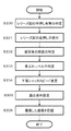
図3は、実施の形態1におけるデジタルカメラ100の動作概要を示すフローチャートである。図3を用いてデジタルカメラ100の動作概要を説明する。
2-1. Operation Overview FIG. 3 is a flowchart showing an operation overview of the
コントローラ130は、使用者によりレリーズ釦201が半押しされたか否かを判定する(S300)。レリーズ釦201の半押しの有無の判定は、コントローラ130がレリーズ釦201の全押しを受け付けるまで実行される。コントローラ130は、使用者によるレリーズ釦201の全押しを受け付ける(S301)と、レリーズ釦201の半押しの有無の判定結果を確定する。
The
続いて、コントローラ130はレリーズ釦201の全押し直前のタイミングに生成された画像データから被写体の照度を判定する(S302)。
Subsequently, the
また、コントローラ130は、使用者がレリーズ釦201を操作したか否かに関わらず、常時(少なくともレリーズ釦201が操作される前から)、ジャイロ160からのジャイロ信号の変化および設定されている焦点距離に基づいて、像ぶれレベルを算出している。コントローラ130は、レリーズ釦201の全押しを受け付けた直前に算出した像ぶれレベルを、像ぶれレベルの判定結果として採用する(S303)。
Further, the
コントローラ130は、上記で判定したレリーズ釦半押しの有無、照度、及び像ぶれレベルに基づいて、選択可能なシャッタスピードの下限を変更する(S304)。コントローラ130は、変更したシャッタスピードの下限を考慮して、適切な露出条件を設定する(S305)。
The
ここで、シャッタスピードの設定について説明する。コントローラ130は、使用者によりマニュアル操作でシャッタスピードが設定される場合を除き、CCD120の感度、被写体の照度、撮影モード等に基づいて、適切なシャッタスピードを設定する機能を有している。その際、設定可能なシャッタスピードの下限値が別途設定されている。本実施形態では、そのシャッタスピードの下限値を、レリーズ釦半押しの有無、照度、及び像ぶれレベルに基づいて適宜変更している。
Here, the setting of the shutter speed will be described. The
最後に、コントローラ130は、設定した露出条件で撮像され、生成された画像データをメモリカード140に記憶する(S306)。
Finally, the
次に、上述した各動作をより詳細に説明する。 Next, each operation described above will be described in more detail.
2−1−1.半押し有無判定
図4は、レリーズ釦201の半押し有無判定処理(図3のステップS300)のフローチャートである。図4を用いて、半押し有無判定処理を説明する。
2-1-1. FIG. 4 is a flowchart of the half-pressed presence / absence determination process of the release button 201 (step S300 in FIG. 3). The half-pressed presence / absence determination process will be described with reference to FIG.
レリーズ釦201が使用者により半押し操作されると、レリーズ釦201から半押し信号が送信され、コントローラ130のポートに、半押し信号を受信したことを示すフラグ(以下「半押しフラグ」と呼ぶ)が設定される。すなわち、半押しフラグがONに設定される。なお、レリーズ釦201の半押し状態が解除されると、半押し信号の送信が停止し、半押しフラグは「OFF」に設定される。
When the
コントローラ130は、所定時間毎(本例では、10msec毎)にポートにおける半押しフラグを確認する(S401)。半押しフラグが「OFF」であるとき、すなわち、使用者がレリーズ釦201の半押し操作を解除したとき、コントローラ130は半押し「無し」と判定する(S405)。
The
コントローラ130は、所定時間(10msec)毎にポートにおける半押しフラグを確認し、3回連続して半押しフラグが「ON」であるか否かを判断する(S403)。ポートに3回連続して半押しフラグが存在している場合、コントローラ130は、半押し「有り」と判定する(S404)。一方、半押しフラグがONであることが3回連続していない場合、コントローラ130は半押し「無し」と判定する(S405)。つまり、一度半押し「有り」と判定された場合であっても、ポートにおいて3回連続して半押しフラグがONされなかったときには、コントローラ130は半押し「無し」と判定する。
The
上記のようにして、レリーズ釦201の半押しは、ステップS401からステップS405までの動作により判定される。一方、レリーズ釦201が全押しされると、上記の半押し判定動作に割り込んで、レリーズ釦201の全押しが判定される。コントローラ130はレリーズ釦201の半押しの有無の判定を、全押しを受け付けるまで定期的に繰り返す。レリーズ釦201の全押しが判定されたときに、半押し「有り」と判定されていれば、半押し「有り」が確定する。また、レリーズ釦201の全押しが判定されたときに、半押し「無し」と判定されていれば、半押し「無し」が確定する。
As described above, half-pressing of the
以上の方法により、コントローラ130は、レリーズ釦201の全押し動作が半押しされずに一気になされたか、半押し動作を経てなされたかを判断できる。また、レリーズ釦201の全押し時には半押しの有無が確定しているため、コントローラ130は使用者の操作状況に応じた瞬時の制御が可能となる。
With the above method, the
なお、上記の方法では、3回連続して半押しフラグがONである場合に半押し「有り」と判定する例を説明したが、この方法に限定されない。すなわち、半押しの有無が判定できれば、半押しフラグの判定回数は3回に限定されない。 In the above-described method, the example in which the half-pressed “present” is determined when the half-pressed flag is ON for three consecutive times has been described. However, the present invention is not limited to this method. That is, if the presence or absence of half-pressing can be determined, the determination number of the half-pressing flag is not limited to three.
2−1−2.被写体の照度の判定
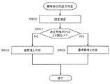
図5は、被写体の照度の判定処理(図3のステップS302)を示すフローチャートである。図5を用いて、被写体の照度判定処理を説明する。
2-1-2. Determination of Subject Illumination FIG. 5 is a flowchart showing the determination processing of the subject illumination (step S302 in FIG. 3). The illuminance determination process for the subject will be described with reference to FIG.
コントローラ130は、CCDイメージセンサ120により生成された画像データの照度を測定する(S500)。続いて、コントローラ130は、測定した照度がEV2よりも明るいか否かを判定する(S501)。
The
測定した照度がEV2よりも明るい場合、コントローラ130は撮像した被写体像の照度が「通常照度」であると判定する(S502)。一方、測定した照度がEV2よりも暗い場合、コントローラ130は撮像した被写体像の照度が「低照度」であると判定する(S503)。なお、低照度であると判定された場合、コントローラ130は、被写体像の照度を、照度の値(EV値)に基づいてより細かく分類する。これは、低照度になる程、適正露出を得るための露光時間が長くなり、像ぶれが生じやすくなることから、より適切に露光時間を設定するためである。
When the measured illuminance is brighter than EV2, the
2−1−3.像ぶれレベルの判定
図6は、像ぶれレベルの判定処理(図3のステップS303)を説明するための図である。図6を用いて、像ぶれレベルの判定について説明する。
2-1-3. Image Blur Level Determination FIG. 6 is a diagram for explaining the image blur level determination process (step S303 in FIG. 3). The determination of the image blur level will be described with reference to FIG.
コントローラ130は、ジャイロ160からの出力信号と、現在の光学系により定まる焦点距離とから、像ぶれ量を算出する。これは、被写体像のぶれ量は、ズームの程度及びカメラのぶれの量に応じて変化するからである。例えば、ジャイロ160により検出されたカメラのぶれ量が同じであっても、ズーム倍率が大きいほど(すなわち焦点距離が長いほど)、被写体像のぶれ量はより大きくなる。像ぶれ量はCCDイメージセンサ120の画素数に換算して算出される。
The
本実施形態では、図6に示すように、像ぶれレベルを0〜3の4段階に設定し、コントローラ130は、像ぶれレベルを像ぶれ量に応じて判定する。例えば、像ぶれ量が1〜5画素分であった場合、像ぶれレベルは0と判定する。また、像ぶれ量が16画素以上の場合、像ぶれレベルは3と判定する。
In the present embodiment, as shown in FIG. 6, the image blur level is set in four stages of 0 to 3, and the
なお、ジャイロ160からの出力信号は波形の変動が大きいため、コントローラ130はこの出力信号を時定数で安定させる必要がある。そのため、コントローラ130は、時系列に受信したジャイロ信号にローパスフィルタをかけ、その結果をジャイロ160からの出力信号として用いる。
Since the output signal from the
コントローラ130は、レリーズ釦201が全押しされた時の像ぶれレベルを、露光時間調節のための情報として採用する。コントローラ130は、レリーズ釦201の全押し操作を受け付けて撮影動作を実行する。そのため、コントローラ130は、レリーズ釦201の全押し時の像ぶれレベルを採用することにより、撮影する被写体像に対して、より適切な露光時間を設定することが可能となる。
The
図6に示すテーブルは一例であり、本実施形態の思想は図6に示す値に限定されるものではない。 The table shown in FIG. 6 is an example, and the idea of the present embodiment is not limited to the values shown in FIG.
また、正確なぶれ検出のためには、ぶれを検出するためのサンプリング時間をある程度の長さ確保する必要がある。特許文献1のカメラでは、レリーズ釦の半押しを検出したときに、ぶれ検出を開始しているため、使用者が半押しを行わずに一気にレリーズ釦を全押しした場合、ぶれ検出のためのサンプリング時間を十分に確保することができず、ぶれ検出に基づいた制御を正確に行うことができないという問題があった。これに対して、本実施形態のコントローラ130は、使用者がレリーズ釦201を操作したか否かに関わらず、常時(少なくともレリーズ釦201が操作される前から)、像ぶれレベルを検出している。そのため、コントローラ130は、ぶれ検出のためのサンプリング時間を十分長く確保することができ、時定数で安定されたジャイロ160からの出力結果を得ることができ、ぶれ検出に基づいた制御を正確に行うことを可能としている。
For accurate shake detection, it is necessary to secure a certain length of sampling time for detecting shake. In the camera of
2−1−4.下限シャッタスピードの変更
図7は、本実施形態のデジタルカメラ100による下限シャッタスピードの変更処理(図3のステップS304)における、下限シャッタスピードの設定値の例を示した図である。図7を用いて、下限シャッタスピードの変更処理を説明する。
2-1-4. Change of Lower Limit Shutter Speed FIG. 7 is a diagram showing an example of a lower limit shutter speed setting value in the lower limit shutter speed change process (step S304 in FIG. 3) by the
前述のように、コントローラ130は、下限シャッタスピードを、レリーズ釦201の半押しの有無と、照度と、像ぶれレベルとに基づいて決定する。図7に示すように、照度と像ぶれレベルが同じであれば、半押し無しの場合の下限シャッタスピードの値は、半押し有りの場合の値よりも、速い(小さい)値に設定されている。また、全体的に、像ぶれ量が大きいほど、下限シャッタスピードの値をより速い(小さい)値に設定する傾向にある。また、全体的に、照度が明るいほど、下限シャッタスピードの値をより速い(小さい)値に設定する傾向にある。レリーズ釦201が半押しされずに一気に全押しされた場合の方が半押しされた場合よりも、発生するカメラのぶれ量が多いと考えられることから、半押し無しの場合の下限シャッタスピードを速い値に設定することで、像ぶれに対するカメラのぶれの影響を低減するようにしている。
As described above, the
具体的には、例えば、半押し「有り」で、像ぶれレベルが「0」、通常照度の場合の下限シャッタスピードは1/8secに設定される。また、例えば、半押し「無し」で、像ぶれレベルが「3」、低照度の場合の下限シャッタスピードは1/30secに設定される。 Specifically, for example, when the half-press is “present”, the image blur level is “0”, and the normal illuminance is set, the lower limit shutter speed is set to 1/8 sec. Further, for example, the lower limit shutter speed is set to 1/30 sec when the half-press is “none”, the image blur level is “3”, and the illuminance is low.
さらに被写体の照度が「低照度」の場合、照度の値(EVの値)に応じて細かく下限シャッタスピードの設定値を設定する。例えば、低照度の場合であって、半押し「有り」、像ぶれレベルが「2」の場合に、EVが「0」のときは、下限シャッタスピードを1/2secに設定し、EVが「1」のときは、下限シャッタスピードを1/4secに設定し、EVが「2」のときは、下限シャッタスピードを1/8secに設定する。このように、低照度の時は、照度の値(EV値)毎に細かく下限シャッタスピードを設定することで、より適切に露光時間を設定することが可能となる。 Further, when the illuminance of the subject is “low illuminance”, the lower limit shutter speed setting value is finely set according to the illuminance value (EV value). For example, in the case of low illuminance, when the half-press is “present” and the image blur level is “2”, and EV is “0”, the lower limit shutter speed is set to 1/2 sec, and EV is “ When “1”, the lower limit shutter speed is set to ¼ sec. When EV is “2”, the lower limit shutter speed is set to 1 / sec. As described above, when the illuminance is low, the exposure time can be set more appropriately by finely setting the lower limit shutter speed for each illuminance value (EV value).
なお、図7に示すテーブルは一例であり、本実施形態の思想は図7に示す値に限定されるものではない。 The table shown in FIG. 7 is an example, and the idea of the present embodiment is not limited to the values shown in FIG.
コントローラ130は適正露出が得られるように、決定されたシャッタスピードに対し、ISO感度を調節する。コントローラ130は、このように露出条件が決定されて撮像され生成された画像データをメモリカード140に記憶する。
The
以上のように、半押しの有無、被写体の照度、像ぶれレベルに応じて下限シャッタスピードを決定することは、特に夜景撮影の場合に有効である。夜景撮影の場合、シャッタスピードが遅い方がきれいな写真を撮影できるが、シャッタスピードを遅くすることは、像ぶれへの影響が大きくなってしまう。しかし、本実施の形態のデジタルカメラ100によれば、夜景撮影であっても、像ぶれレベルが低いときは、像ぶれの影響を許容できる範囲でシャッタスピードをできるだけ遅く設定できる。
As described above, determining the lower limit shutter speed according to the presence / absence of half-press, the illuminance of the subject, and the image blur level is particularly effective in night scene shooting. In night scene shooting, a slower shutter speed can capture a beautiful photograph, but a slower shutter speed has a greater effect on image blurring. However, according to the
また、一般にカメラ初心者はレリーズ釦201の半押しをせずに、撮影のために一気にレリーズ釦201を全押しすることが多い。このようにレリーズ釦201を一気に全押しすることにより、デジタルカメラ100のぶれが大きくなる可能性が高くなる。また、カメラ初心者はカメラの保持に不慣れなため、レリーズ釦201の押下時にカメラ本体のぶれが大きくなる可能性が高い。このようにカメラ初心者は撮影時に像ぶれを起こす可能性が高い。しかし、本実施の形態のデジタルカメラ100によれば、レリーズ釦201の全押し時において半押しの有無および像ぶれレベルの判定を行い、半押しが無いときでも適切な露光時間の設定ができる。また、使用者のレリーズ釦201の全押しの瞬間にはすでにレリーズ釦の半押しの有無および像ぶれレベルの判定がされているため、瞬間的に露光時間の設定ができる。このため、本実施の形態のデジタルカメラ100によれば、カメラ初心者の使用に対しても、撮影時に像ぶれを起こす可能性を低減できる。
In general, a camera beginner often presses the
3.まとめ
実施の形態1のデジタルカメラ100は、光学系110を介して生成された被写体像を撮像して画像データを生成するCCDイメージセンサ120と、生成した画像データをメモリカード140に記録するカードスロット141とからなる構成と、CCDイメージセンサ120に対する露光時間を調節するシャッタ114およびコントローラ130からなる構成と、自機のぶれを検出するジャイロ160およびコントローラ130からなる構成と、使用者により操作され、全押し状態および半押し状態をとり得るレリーズ釦201と、レリーズ釦201が全押し状態となったときに、CCDイメージセンサ120が生成する画像データをメモリカード140に記録するようカードスロット141を制御するコントローラ130とを備える。コントローラ130は、レリーズ釦201が全押し状態となる前に半押し状態となったか否かを判定し、その判定結果と、ジャイロ160およびコントローラ130とからなる構成で検出された自機のぶれとに基づいて、CCDイメージセンサ120に対する露光時間を調節する。この構成により、デジタルカメラ100は、レリーズ釦201の全押し時において、半押しの有無の判定結果および自機のぶれの検出結果とに基づいて露光時間を適切に調節することができる。
3. Summary The
その他の実施形態
デジタルカメラ100は、被写体のシーンを判定するシーン判定手段をさらに備えていてもよい。そして、例えば、人物のいない夜景、人物を含む夜景、夜景以外などのシーンを判別し、判別したシーンを考慮して下限シャッタスピードを設定してもよい。例えば、図8に示すように、テーブルに判別シーンごとの下限シャッタスピードを設定してもよい。夜景の場合、被写体の照度が低くなることから、設定されるシャッタスピードは、その下限値に設定される。なお、図8に示すテーブルは一例であり、本実施形態の思想は図8に示す値に限定されるものではない。
Other Embodiments The
実施の形態1では、露光時間の調整として、設定可能なシャッタスピードの下限を変更したが、設定可能なシャッタスピードの下限の代わりに、レリーズ釦全押し時に設定されているシャッタスピードの値自体を変更してもよい。 In the first embodiment, the lower limit of the settable shutter speed is changed as the exposure time adjustment. Instead of the lower limit of the settable shutter speed, the shutter speed value itself set when the release button is fully pressed is used. It may be changed.
上記の実施の形態の思想は、交換レンズ式のデジタルカメラにも適用可能である。このとき、交換レンズにジャイロセンサが搭載されている場合であっても、デジタルカメラ本体がジャイロセンサからの検出情報を取得できる構成であれば、上記実施の形態の思想が適用可能であることは、当業者であれば自明である。また、上記の実施の形態の思想は、デジタルカメラ以外の撮像装置にも適用可能である。すなわち、上記の思想が、画像を撮像する装置であって、撮像装置のぶれを検出する機能を有する、ムービーカメラ、カメラ付き携帯電話などの撮像装置にも適用することができることは言うまでも無い。 The idea of the above embodiment can also be applied to an interchangeable lens type digital camera. At this time, even if the gyro sensor is mounted on the interchangeable lens, the idea of the above embodiment can be applied as long as the digital camera body can obtain detection information from the gyro sensor. Those skilled in the art will appreciate. Further, the idea of the above embodiment can be applied to an imaging apparatus other than a digital camera. That is, it is needless to say that the above-described idea can be applied to an imaging device such as a movie camera or a camera-equipped mobile phone that has a function of detecting a shake of the imaging device. .
本発明は、ぶれを検出する装置を搭載したデジタルカメラ、ムービーカメラ、カメラ付き携帯電話などの撮像装置に有用である。 The present invention is useful for an imaging device such as a digital camera, a movie camera, or a camera-equipped mobile phone equipped with a device for detecting blur.
100…デジタルカメラ
111…フォーカスレンズ
112…ズームレンズ
113…絞り
114…シャッタ
120…CCDイメージセンサ
121…AFE(Analog Front End)
122…画像処理部
123…液晶ディスプレイ
124…バッファメモリ
130…コントローラ
140…メモリカード
141…カードスロット
142…フラッシュメモリ
150…操作部
160…ジャイロセンサ
201…レリーズ釦
202…ズームダイヤル
203…選択釦
DESCRIPTION OF
122 ...
Claims (10)
前記生成した画像データを記録媒体に記録する記録手段と、
前記撮像手段に対する露光時間を調節する調節手段と、
自機のぶれを検出するぶれ検出手段と、
使用者により操作され、第一の操作状態および第二の操作状態をとり得る操作手段と、
前記操作手段が第一の操作状態となったときに、前記撮像手段が生成する画像データを前記記録媒体に記録するよう記録手段を制御する制御手段と、を備え、
前記制御手段は、前記操作手段が前記第一の操作状態となる前に前記第二の操作状態となったか否かを判定し、その判定結果と、前記ぶれ検出手段で検出された自機のぶれとに基づいて、前記調節手段の露光時間を調節する、
撮像装置。 An imaging unit that captures a subject image generated via an optical system and generates image data;
Recording means for recording the generated image data on a recording medium;
Adjusting means for adjusting an exposure time for the imaging means;
A shake detection means for detecting the shake of the aircraft,
An operation means that is operated by a user and can take a first operation state and a second operation state;
Control means for controlling the recording means so as to record image data generated by the imaging means on the recording medium when the operating means is in a first operation state;
The control means determines whether or not the operation means is in the second operation state before becoming the first operation state, and the determination result and the own detection unit detected by the shake detection means. Adjusting the exposure time of the adjusting means based on the blur;
Imaging device.
前記制御手段は、前記判定結果と前記ぶれ検出手段で検出された自機のぶれに加えてさらに前記照度に基づいて前記露光時間を調節する、
請求項1または2に記載の撮像装置。 Illuminance acquisition means for acquiring information on the illuminance of the subject from the image data,
The control means further adjusts the exposure time based on the illuminance in addition to the determination result and the shake of the own device detected by the shake detection means.
The imaging device according to claim 1 or 2.
請求項1または2に記載の撮像装置。 The control means adjusts the exposure time based on the determination result and the focal length determined by the optical system in addition to the own camera shake detected by the shake detection means,
The imaging device according to claim 1 or 2.
前記生成した画像データを記録媒体に記録する記録手段と、
前記撮像手段に対する露光時間を調節する調節手段と、
自機のぶれに関する情報を取得する取得手段と、
使用者により操作され、第一の操作状態および第二の操作状態をとり得る操作手段と、
前記操作手段が第一の操作状態となったときに、前記撮像手段が生成する画像データを前記記録媒体に記録するよう記録手段を制御する制御手段と、を備え、
前記制御手段は、前記操作手段が前記第一の操作状態となる前に前記第二の操作状態となったか否かを判定し、その判定結果と、前記取得手段で取得した自機のぶれに関する情報とに基づいて、前記調節手段の露光時間を調節する、
撮像装置。 An imaging unit that captures a subject image generated via an optical system and generates image data;
Recording means for recording the generated image data on a recording medium;
Adjusting means for adjusting an exposure time for the imaging means;
An acquisition means for acquiring information relating to the shake of the aircraft;
An operation means that is operated by a user and can take a first operation state and a second operation state;
Control means for controlling the recording means so as to record image data generated by the imaging means on the recording medium when the operating means is in a first operation state;
The control means determines whether or not the operation means is in the second operation state before becoming the first operation state, and relates to the determination result and the shake of the own device acquired by the acquisition means. Adjusting the exposure time of the adjusting means based on the information;
Imaging device.
Priority Applications (1)
| Application Number | Priority Date | Filing Date | Title |
|---|---|---|---|
| JP2010168279A JP2011050048A (en) | 2009-07-27 | 2010-07-27 | Imaging apparatus |
Applications Claiming Priority (2)
| Application Number | Priority Date | Filing Date | Title |
|---|---|---|---|
| JP2009174073 | 2009-07-27 | ||
| JP2010168279A JP2011050048A (en) | 2009-07-27 | 2010-07-27 | Imaging apparatus |
Publications (2)
| Publication Number | Publication Date |
|---|---|
| JP2011050048A true JP2011050048A (en) | 2011-03-10 |
| JP2011050048A5 JP2011050048A5 (en) | 2013-09-12 |
Family
ID=43496996
Family Applications (1)
| Application Number | Title | Priority Date | Filing Date |
|---|---|---|---|
| JP2010168279A Pending JP2011050048A (en) | 2009-07-27 | 2010-07-27 | Imaging apparatus |
Country Status (3)
| Country | Link |
|---|---|
| US (1) | US8345150B2 (en) |
| JP (1) | JP2011050048A (en) |
| CN (1) | CN101968596A (en) |
Cited By (1)
| Publication number | Priority date | Publication date | Assignee | Title |
|---|---|---|---|---|
| WO2024048069A1 (en) * | 2022-08-30 | 2024-03-07 | ソニーグループ株式会社 | Information processing device, information processing method, and program |
Families Citing this family (4)
| Publication number | Priority date | Publication date | Assignee | Title |
|---|---|---|---|---|
| CN103905735B (en) * | 2014-04-17 | 2017-10-27 | 深圳市世尊科技有限公司 | The mobile terminal and its dynamic for chasing after shooting function with dynamic chase after shooting method |
| CN107615744B (en) * | 2016-04-27 | 2020-07-24 | 华为技术有限公司 | Image shooting parameter determining method and camera device |
| CN106791459A (en) * | 2016-11-17 | 2017-05-31 | 努比亚技术有限公司 | A kind of signal processing method and equipment |
| CN108111744A (en) * | 2016-11-25 | 2018-06-01 | 努比亚技术有限公司 | A kind of filming apparatus and method |
Citations (4)
| Publication number | Priority date | Publication date | Assignee | Title |
|---|---|---|---|---|
| JPH05207345A (en) * | 1992-01-28 | 1993-08-13 | Canon Inc | Picture recorder |
| JPH08294041A (en) * | 1995-04-20 | 1996-11-05 | Hitachi Ltd | Image pickup device |
| JP3550608B2 (en) * | 1995-09-13 | 2004-08-04 | 株式会社ニコン | Camera shake correction device |
| JP2006091398A (en) * | 2004-09-24 | 2006-04-06 | Casio Comput Co Ltd | Camera apparatus |
Family Cites Families (28)
| Publication number | Priority date | Publication date | Assignee | Title |
|---|---|---|---|---|
| JP2622485B2 (en) | 1992-12-21 | 1997-06-18 | 株式会社ニコン | Camera shake prevention camera |
| US6272289B1 (en) * | 1998-09-14 | 2001-08-07 | Canon Kabushiki Kaisha | Camera |
| JP2000180911A (en) * | 1998-12-15 | 2000-06-30 | Canon Inc | Image blur correcting device |
| JP2001157110A (en) * | 1999-11-30 | 2001-06-08 | Olympus Optical Co Ltd | Electronic camera device |
| JP3939889B2 (en) * | 2000-02-01 | 2007-07-04 | ペンタックス株式会社 | Image blur prevention digital camera |
| JP2004012603A (en) * | 2002-06-04 | 2004-01-15 | Canon Inc | Apparatus for prevention of image shake, and camera |
| JP4272863B2 (en) * | 2002-09-20 | 2009-06-03 | キヤノン株式会社 | Camera and camera system |
| JP2004361486A (en) * | 2003-06-02 | 2004-12-24 | Nikon Corp | Digital still camera |
| JP2005181355A (en) * | 2003-12-15 | 2005-07-07 | Canon Inc | Imaging apparatus |
| JP4173457B2 (en) * | 2004-03-12 | 2008-10-29 | 富士フイルム株式会社 | Imaging apparatus and control method thereof |
| JP2006203477A (en) * | 2005-01-19 | 2006-08-03 | Fuji Photo Film Co Ltd | Photographing apparatus |
| US20060170816A1 (en) * | 2005-01-28 | 2006-08-03 | Silverstein D A | Method and system for automatically adjusting exposure parameters of an imaging device |
| JP2006245815A (en) * | 2005-03-01 | 2006-09-14 | Fuji Photo Film Co Ltd | Imaging apparatus |
| JP2007033543A (en) * | 2005-07-22 | 2007-02-08 | Fujifilm Holdings Corp | Imaging apparatus |
| JP4766320B2 (en) * | 2006-02-06 | 2011-09-07 | カシオ計算機株式会社 | Imaging apparatus and program thereof |
| JP2007225763A (en) * | 2006-02-22 | 2007-09-06 | Sony Corp | Imaging apparatus, imaging method, and program |
| US7877004B2 (en) * | 2006-03-03 | 2011-01-25 | Olympus Imaging Corp. | Imaging apparatus and imaging method |
| JP4594257B2 (en) * | 2006-03-10 | 2010-12-08 | 富士フイルム株式会社 | Digital imaging device |
| JP2007300595A (en) * | 2006-04-06 | 2007-11-15 | Winbond Electron Corp | Method of avoiding shaking during still image photographing |
| JP4823179B2 (en) * | 2006-10-24 | 2011-11-24 | 三洋電機株式会社 | Imaging apparatus and imaging control method |
| JP2008209650A (en) | 2007-02-26 | 2008-09-11 | Olympus Imaging Corp | Imaging apparatus and control method for imaging apparatus |
| JP2009003219A (en) * | 2007-06-22 | 2009-01-08 | Seiko Epson Corp | Camera shake preventing device, camera shake preventing method and imaging equipment |
| JP2009017078A (en) * | 2007-07-03 | 2009-01-22 | Fujifilm Corp | Digital still camera and its operation controlling method |
| JP4986175B2 (en) * | 2007-12-28 | 2012-07-25 | カシオ計算機株式会社 | Imaging apparatus and program |
| JP5065060B2 (en) * | 2008-01-16 | 2012-10-31 | キヤノン株式会社 | Imaging apparatus and control method thereof |
| CN101489035A (en) * | 2008-01-16 | 2009-07-22 | 三洋电机株式会社 | Image shooting apparatus and blur correction method |
| JP5067234B2 (en) | 2008-03-28 | 2012-11-07 | カシオ計算機株式会社 | Imaging apparatus, imaging method, and imaging control program |
| US20100277603A1 (en) * | 2009-04-29 | 2010-11-04 | Apple Inc. | Image Capture Device to Minimize the Effect of Device Movement |
-
2010
- 2010-07-23 US US12/842,236 patent/US8345150B2/en not_active Expired - Fee Related
- 2010-07-27 CN CN2010102396081A patent/CN101968596A/en active Pending
- 2010-07-27 JP JP2010168279A patent/JP2011050048A/en active Pending
Patent Citations (4)
| Publication number | Priority date | Publication date | Assignee | Title |
|---|---|---|---|---|
| JPH05207345A (en) * | 1992-01-28 | 1993-08-13 | Canon Inc | Picture recorder |
| JPH08294041A (en) * | 1995-04-20 | 1996-11-05 | Hitachi Ltd | Image pickup device |
| JP3550608B2 (en) * | 1995-09-13 | 2004-08-04 | 株式会社ニコン | Camera shake correction device |
| JP2006091398A (en) * | 2004-09-24 | 2006-04-06 | Casio Comput Co Ltd | Camera apparatus |
Cited By (1)
| Publication number | Priority date | Publication date | Assignee | Title |
|---|---|---|---|---|
| WO2024048069A1 (en) * | 2022-08-30 | 2024-03-07 | ソニーグループ株式会社 | Information processing device, information processing method, and program |
Also Published As
| Publication number | Publication date |
|---|---|
| US20110019069A1 (en) | 2011-01-27 |
| US8345150B2 (en) | 2013-01-01 |
| CN101968596A (en) | 2011-02-09 |
Similar Documents
| Publication | Publication Date | Title |
|---|---|---|
| JP2006208691A (en) | Imaging apparatus, its camera main body, and interchangeable lens | |
| JP2007264196A (en) | Strobe control unit and method | |
| KR20070086061A (en) | Image processing and image processing program of image processing | |
| US8872929B2 (en) | Picture imaging apparatus and imaging control method | |
| JP2007150802A (en) | Control apparatus, photographing apparatus, control method of photographing apparatus, and control program | |
| JPWO2007057971A1 (en) | Digital camera, electronic device equipped with digital camera, imaging method of digital camera, and storage medium storing digital camera program | |
| JP2011050048A (en) | Imaging apparatus | |
| US20060197866A1 (en) | Image taking apparatus | |
| JP2004104463A (en) | Imaging device | |
| JP5618765B2 (en) | Imaging apparatus and control method thereof | |
| JP4717840B2 (en) | Imaging apparatus and control method thereof | |
| JP2007041206A (en) | Photographing apparatus | |
| JP2013088446A (en) | Imaging apparatus | |
| JP2007028546A (en) | Imaging apparatus | |
| JP2005184246A (en) | Imaging unit | |
| JP2007300269A (en) | Exposure correcting device, photographing device, image restoring device, exposure value setting device, exposure correction value calculation method and control program | |
| JP5810304B2 (en) | Imaging apparatus and information display method in imaging apparatus | |
| JP2009135670A (en) | Image device and its control method | |
| JP2008085839A (en) | Error notification method of imaging apparatus, and imaging apparatus | |
| JP2007013586A (en) | Image pickup device | |
| JP4378237B2 (en) | Imaging device | |
| JP2009015184A (en) | Imaging device | |
| JP2008092047A (en) | Electronic camera | |
| WO2020158007A1 (en) | Image-capturing device | |
| JP2006339867A (en) | Photographing apparatus and control method thereof |
Legal Events
| Date | Code | Title | Description |
|---|---|---|---|
| A521 | Request for written amendment filed |
Free format text: JAPANESE INTERMEDIATE CODE: A523 Effective date: 20130726 |
|
| A621 | Written request for application examination |
Free format text: JAPANESE INTERMEDIATE CODE: A621 Effective date: 20130726 |
|
| A977 | Report on retrieval |
Free format text: JAPANESE INTERMEDIATE CODE: A971007 Effective date: 20140214 |
|
| A131 | Notification of reasons for refusal |
Free format text: JAPANESE INTERMEDIATE CODE: A131 Effective date: 20140218 |
|
| A02 | Decision of refusal |
Free format text: JAPANESE INTERMEDIATE CODE: A02 Effective date: 20140729 |