JP2011032003A - Recorder - Google Patents

Recorder Download PDF

Info

Publication number
JP2011032003A
JP2011032003A JP2009177436A JP2009177436A JP2011032003A JP 2011032003 A JP2011032003 A JP 2011032003A JP 2009177436 A JP2009177436 A JP 2009177436A JP 2009177436 A JP2009177436 A JP 2009177436A JP 2011032003 A JP2011032003 A JP 2011032003A
Authority
JP
Japan
Prior art keywords
recording medium
width
recording
guide
insertion port
Prior art date
Legal status (The legal status is an assumption and is not a legal conclusion. Google has not performed a legal analysis and makes no representation as to the accuracy of the status listed.)
Withdrawn
Application number
JP2009177436A
Other languages
Japanese (ja)
Inventor
Akira Nakazawa
章 中沢
Current Assignee (The listed assignees may be inaccurate. Google has not performed a legal analysis and makes no representation or warranty as to the accuracy of the list.)
Seiko Epson Corp
Original Assignee
Seiko Epson Corp
Priority date (The priority date is an assumption and is not a legal conclusion. Google has not performed a legal analysis and makes no representation as to the accuracy of the date listed.)
Filing date
Publication date
Application filed by Seiko Epson Corp filed Critical Seiko Epson Corp
Priority to JP2009177436A priority Critical patent/JP2011032003A/en
Publication of JP2011032003A publication Critical patent/JP2011032003A/en
Withdrawn legal-status Critical Current

Links

Images

Landscapes

  • Sheets, Magazines, And Separation Thereof (AREA)

Abstract

<P>PROBLEM TO BE SOLVED: To insert a recording medium even into a position exceeding this range, by guiding the recording medium to the desired range of an insertion port for insetting the recording medium, in a recorder. <P>SOLUTION: A dot impact printer 10 has a recording head 18 for recording on the recording medium, and has a manual feeding port 15 having a width of a recordable range P or more determined as a recordable range by the recording head 18, and has a paper guide 61 for regulating the width of the manual feeding port 15 in a width smaller than the recordable range P. The paper guide 61 has a guide part 64C capable of inserting the recording medium Sc into the manual feeding port 15 by getting over the paper guide 61. <P>COPYRIGHT: (C)2011,JPO&amp;INPIT

Description

本発明は、記録媒体が挿入される挿入口を備えた記録装置に関する。   The present invention relates to a recording apparatus having an insertion slot into which a recording medium is inserted.

従来、記録装置において、挿入口における記録媒体の位置を特定の位置に保持するため、記録媒体の給紙台に、記録媒体の幅方向の端を案内するガイドを設けたものが知られている。このガイドは、例えば、様々なサイズの記録媒体に対応するためにスライド可能に構成されている(例えば、特許文献1参照)。   2. Description of the Related Art Conventionally, in a recording apparatus, in order to hold the position of a recording medium at an insertion port at a specific position, a recording medium feeding base is provided with a guide for guiding an end in the width direction of the recording medium. . For example, the guide is configured to be slidable to cope with recording media of various sizes (see, for example, Patent Document 1).

特開平11−292347号公報JP-A-11-292347

ところで、記録媒体を案内すべき範囲が限られている場合には、記録媒体の幅方向の端を案内するガイドを広範囲で自在にスライド可能にする必要性が薄い。このため、ガイドの位置を固定的にして、構造を単純化することが望ましいが、ガイドを固定してしまうと、ガイドの位置を超えるサイズの記録媒体の使用の妨げになってしまうという問題がある。また、ガイドにより案内される範囲を超えた位置に記録媒体を挿入することも困難になってしまうという問題がある。
本発明は、上述した事情に鑑みてなされたものであり、記録媒体が挿入される挿入口の所望の範囲に記録媒体を案内するとともに、この範囲を超える位置に記録媒体を挿入することも可能な記録装置を提供することを目的とする。
By the way, when the range in which the recording medium should be guided is limited, there is little need to make the guide for guiding the end in the width direction of the recording medium freely slidable in a wide range. Therefore, it is desirable to simplify the structure by fixing the position of the guide. However, if the guide is fixed, there is a problem that the use of a recording medium having a size exceeding the position of the guide is hindered. is there. Also, there is a problem that it becomes difficult to insert the recording medium at a position beyond the range guided by the guide.
The present invention has been made in view of the above-described circumstances, and it is possible to guide the recording medium to a desired range of the insertion port into which the recording medium is inserted and to insert the recording medium at a position exceeding this range. It is an object to provide a simple recording apparatus.

上記目的を達成するため、本発明は、記録媒体に記録を行う記録部を備えた記録装置において、前記記録部により記録可能な範囲として定められた記録可能範囲以上の幅を有する挿入口を有し、前記挿入口の幅を、前記記録可能範囲よりも小さい幅に規制する幅規制部を備え、前記幅規制部は、該幅規制部を乗り越えて前記記録媒体を前記挿入口に挿入可能とする案内部を有することを特徴とする記録装置を提供する。
この構成によれば、挿入口の幅が幅規制部によって記録部の記録可能範囲よりも小さい幅に規制されるため、記録可能範囲よりも小さい所望の範囲に記録媒体を案内できる。さらに、幅規制部が有する案内部を乗り越えて記録媒体を挿入可能であるため、幅規制部に挿入口の幅を規制されないようにして所望の位置に記録媒体を挿入することもできる。これにより、記録媒体が挿入される挿入口の所望の範囲に記録媒体を案内すると共に、この範囲を超える位置に記録媒体を挿入することもできる。
In order to achieve the above object, the present invention provides a recording apparatus including a recording unit that performs recording on a recording medium, and has an insertion slot having a width equal to or larger than a recordable range defined as a recordable range by the recording unit. And a width restricting portion that restricts the width of the insertion port to a width smaller than the recordable range, and the width restricting portion can overcome the width restricting portion and insert the recording medium into the insertion port. Provided is a recording apparatus having a guide portion.
According to this configuration, the width of the insertion slot is regulated to a width smaller than the recordable range of the recording unit by the width regulating unit, so that the recording medium can be guided to a desired range smaller than the recordable range. Furthermore, since the recording medium can be inserted over the guide portion of the width restricting portion, the recording medium can be inserted at a desired position so that the width restricting portion does not restrict the width of the insertion port. Accordingly, the recording medium can be guided to a desired range of the insertion slot into which the recording medium is inserted, and the recording medium can be inserted at a position exceeding this range.

また、本発明は、記録媒体に記録を行う記録部と、前記記録媒体を挿入する挿入口と、前記挿入口から挿入された前記記録媒体を搬送する搬送部とを備え、前記挿入口は、前記搬送部によって前記記録媒体が搬送される搬送範囲に対応した幅を有する開口であり、前記挿入口において前記記録媒体を挿入可能な幅を、より小さい幅に規制する幅規制部を備え、前記幅規制部は、該幅規制部を乗り越えて前記記録媒体を前記挿入口に挿入可能とする案内部を有することを特徴とする記録装置を提供する。
この構成によれば、挿入口の幅が幅規制部によって搬送部の搬送範囲よりも小さい幅に規制されるため、搬送範囲よりも小さい所望の範囲に記録媒体を案内できる。さらに、幅規制部が有する案内部を乗り越えて記録媒体を挿入可能であるため、幅規制部に挿入口の幅を規制されないようにして所望の位置に記録媒体を挿入することもできる。これにより、記録媒体が挿入される挿入口の所望の範囲に記録媒体を案内できると共に、この範囲を超える位置に記録媒体を挿入することもできる。
Further, the present invention comprises a recording unit for recording on a recording medium, an insertion port for inserting the recording medium, and a transport unit for conveying the recording medium inserted from the insertion port, An opening having a width corresponding to a conveyance range in which the recording medium is conveyed by the conveyance unit, and includes a width regulating unit that regulates a width in which the recording medium can be inserted into the insertion port to a smaller width, The width restricting portion includes a guide portion that allows the recording medium to be inserted into the insertion port over the width restricting portion.
According to this configuration, since the width of the insertion port is regulated to a width smaller than the conveyance range of the conveyance unit by the width regulating unit, the recording medium can be guided to a desired range smaller than the conveyance range. Furthermore, since the recording medium can be inserted over the guide portion of the width restricting portion, the recording medium can be inserted at a desired position so that the width restricting portion does not restrict the width of the insertion port. Accordingly, the recording medium can be guided to a desired range of the insertion slot into which the recording medium is inserted, and the recording medium can be inserted at a position exceeding this range.

また、前記挿入口の縁に連なり、前記挿入口に進入する記録媒体を支持する媒体挿入台を設け、前記幅規制部は、前記媒体挿入台に立設された凸部であり、前記案内部は、前記幅規制部の頂部から前記挿入口の奥側に向かって下方に傾斜する斜面で構成されても良い。
この場合、案内部が挿入口の奥側に向かって下方に傾斜した斜面で構成され、記録媒体が斜面に沿うように案内されるため、記録媒体を挿入口の奥側にスムーズに挿入できる。また、記録媒体が挿入口から排出される際に斜面に沿うように排出されるため、記録媒体が幅規制部に引っ掛かることが無く、記録媒体をスムーズに排出できる。
さらに、前記挿入口から挿入された前記記録媒体の表面を光学的に読み取る読取部を備え、前記幅規制部は、前記挿入口において前記記録媒体を挿入可能な幅を、前記読取部の読み取り可能範囲に合わせて規制しても良い。
この場合、幅規制部によって、挿入口の幅が読取部の読み取り可能範囲に合わせて規制され、記録媒体が読取部の読み取り可能範囲に案内されるため、確実に記録媒体の情報を読み取りできる。
In addition, a medium insertion base that is connected to an edge of the insertion opening and supports a recording medium that enters the insertion opening is provided, and the width restricting portion is a convex portion standing on the medium insertion base, and the guide portion May be composed of a slope inclined downward from the top of the width restricting portion toward the back side of the insertion port.
In this case, since the guide portion is composed of a slope inclined downward toward the back side of the insertion slot, and the recording medium is guided along the slope, the recording medium can be smoothly inserted into the back side of the insertion slot. In addition, since the recording medium is discharged along the inclined surface when the recording medium is discharged from the insertion port, the recording medium is not caught by the width regulating portion, and the recording medium can be discharged smoothly.
The reading unit further includes a reading unit that optically reads the surface of the recording medium inserted from the insertion port, and the width restricting unit can read the width in which the recording medium can be inserted into the insertion port. You may regulate according to the range.
In this case, the width restricting portion restricts the width of the insertion slot in accordance with the readable range of the reading unit, and the recording medium is guided to the readable range of the reading unit, so that information on the recording medium can be read reliably.

さらにまた、前記挿入口から挿入された前記記録媒体の向きを、前記搬送部による搬送方向に沿って整える整列機構を備え、前記整列機構は、前記記録媒体の後端が前記挿入口から突出する位置で前記記録媒体の向きを整えても良い。
この場合、整列動作が記録媒体の後端が挿入口から突出する位置機構で行われ、整列の際に幅規制部によって記録媒体の移動可能な範囲が規制されるため、記録媒体が整列動作の影響を受けて搬送されるべき位置からずれてしまうことを防止できる。
Furthermore, an alignment mechanism that adjusts the direction of the recording medium inserted from the insertion port along a conveyance direction by the conveyance unit, and the alignment mechanism has a rear end of the recording medium that protrudes from the insertion port. The orientation of the recording medium may be adjusted at the position.
In this case, the alignment operation is performed by a position mechanism in which the rear end of the recording medium protrudes from the insertion port, and the range in which the recording medium can be moved is regulated by the width regulating unit during the alignment. It is possible to prevent the position from being transported due to the influence.

また、前記幅規制部を前記挿入口の幅方向の一端側に設け、前記挿入口の他端側に、前記幅規制部の前記案内部と略同一高さで前記記録媒体が乗り越え可能な支持部を設けても良い。
この場合、挿入口の幅方向の一端側に幅規制部を設け、他端側に幅規制部の案内部と略同一高さで記録媒体が乗り越え可能な支持部を設けたため、記録媒体を幅方向に渡って略同一高さで支持でき、記録媒体を略水平な状態で案内できる。このため、記録媒体をスムーズに搬送できる。
また、前記支持部の下方には、前記搬送部によって搬送される前記記録媒体が通過可能な空間が形成され、前記支持部は、前記空間を通過する前記記録媒体の上方から前記記録媒体を押さえる上面ガイドを備えても良い。
この場合、支持部の下方の空間を通して記録媒体を挿入できるため、挿入口の幅に影響を及ぼすことなく支持部を設けることができる。また、上面ガイドによって記録媒体を上方から押さえるため、記録媒体の浮き上がりを防止できる。
The width restricting portion is provided on one end side in the width direction of the insertion port, and the recording medium can be supported on the other end side of the insertion port at a height substantially equal to the guide portion of the width restricting portion. A part may be provided.
In this case, the width restricting portion is provided on one end side in the width direction of the insertion slot, and the support portion on the other end side is provided with a support portion on which the recording medium can get over at substantially the same height as the guide portion of the width restricting portion. It can be supported at substantially the same height across the direction, and the recording medium can be guided in a substantially horizontal state. For this reason, a recording medium can be conveyed smoothly.
In addition, a space through which the recording medium conveyed by the conveying unit can pass is formed below the support unit, and the support unit presses the recording medium from above the recording medium passing through the space. An upper surface guide may be provided.
In this case, since the recording medium can be inserted through the space below the support portion, the support portion can be provided without affecting the width of the insertion slot. Further, since the recording medium is pressed from above by the upper surface guide, it is possible to prevent the recording medium from being lifted.

本発明によれば、記録装置において、記録媒体が挿入される挿入口の所望の範囲に記録媒体を案内できると共に、この範囲を超える位置に記録媒体を挿入することもできる。   According to the present invention, in the recording apparatus, the recording medium can be guided to a desired range of the insertion port into which the recording medium is inserted, and the recording medium can be inserted at a position exceeding this range.

第1の実施の形態のドットインパクトプリンターの外観斜視図である。1 is an external perspective view of a dot impact printer according to a first embodiment. プリンター本体を示す斜視図である。FIG. 2 is a perspective view showing a printer body. プリンター本体の側断面図である。FIG. 3 is a side sectional view of the printer body. プリンター本体の前部を示す平面図である。FIG. 3 is a plan view showing a front portion of the printer main body. プリンター本体の前部の側断面図である。FIG. 3 is a side sectional view of a front portion of the printer main body. 第2の実施の形態のドットインパクトプリンターの正面図である。It is a front view of a dot impact printer of a second embodiment.

以下、本発明の実施形態について図面を参照して説明する。
[第1の実施の形態]
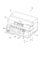
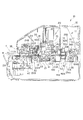
図1は、第1の実施の形態に係るドットインパクトプリンター(記録装置)の外観を示す正面斜視図である。図2は、プリンター本体11を示す外観斜視図である。図3は、図1のドットインパクトプリンター10を示す側断面図である。
図1に示す記録装置としてのドットインパクトプリンター10は、記録ヘッド18(図2、図3参照)が備える複数の記録ワイヤーを、リボンカートリッジ(図示略)から繰り出したインクリボン(図示略)を介して記録媒体Saに押し付け、この記録媒体Saの記録面上にドットを形成することにより、文字や記号、画像等を記録するものである。
また、ドットインパクトプリンター10は、光学読取装置200(図3参照)を有し、この光学読取装置200によって記録媒体Saの表面に表示された文字や記号、画像等を読み取り可能である。
以下の説明では、図3中の左側をフロント(前)側とし、図3中の右側をリア(後)側とする。
Embodiments of the present invention will be described below with reference to the drawings.
[First Embodiment]
FIG. 1 is a front perspective view showing an appearance of a dot impact printer (recording apparatus) according to the first embodiment. FIG. 2 is an external perspective view showing the printer main body 11. FIG. 3 is a side sectional view showing the dot impact printer 10 of FIG.
A dot impact printer 10 as a recording apparatus shown in FIG. 1 includes a plurality of recording wires provided in a recording head 18 (see FIGS. 2 and 3) via an ink ribbon (not shown) that is fed out from a ribbon cartridge (not shown). Then, the characters, symbols, images and the like are recorded by pressing the recording medium Sa and forming dots on the recording surface of the recording medium Sa.
The dot impact printer 10 includes an optical reading device 200 (see FIG. 3), and can read characters, symbols, images, and the like displayed on the surface of the recording medium Sa by the optical reading device 200.
In the following description, the left side in FIG. 3 is the front (front) side, and the right side in FIG. 3 is the rear (rear) side.

ドットインパクトプリンター10で使用可能な記録媒体としては、所定長さに切断されたカットシートと、複数枚が連接された連続シートとがある。カットシートとしては、例えば単票紙や単票複写紙などの他、通帳や葉書、封筒、カードなどがあり、連続シートは複数枚の紙が連接された連続紙や複写紙が連接された連続複写紙等を含む。
図1に示す記録媒体Saは通帳であり、ここでいう通帳とは、複数枚の記録用紙が綴じられた冊子形態となっており、この冊子を開いた内側の面が記録面となっている。さらに、通帳の裏表紙には、磁気ストライプMSが設けられている。この磁気ストライプMSには磁気的に各種情報を記録し、読み取ることが可能である。
なお、以下の説明において、矩形の記録媒体Saの4辺のうち、ドットインパクトプリンター10へ向かって差し込まれる側の辺を先端とし、この先端と対向する側の辺を後端とする。
Recording media that can be used in the dot impact printer 10 include a cut sheet cut to a predetermined length and a continuous sheet in which a plurality of sheets are connected. Cut sheets include, for example, cut paper and cut copy paper, as well as passbooks, postcards, envelopes, cards, etc. Continuous sheets are continuous paper with multiple sheets connected or continuous with copy paper connected. Includes copy paper.
The recording medium Sa shown in FIG. 1 is a passbook, and the passbook here is in the form of a booklet in which a plurality of recording sheets are bound, and the inner surface of the booklet is the recording surface. . Further, a magnetic stripe MS is provided on the back cover of the passbook. Various information can be magnetically recorded and read in the magnetic stripe MS.
In the following description, of the four sides of the rectangular recording medium Sa, the side that is inserted toward the dot impact printer 10 is the leading end, and the side that faces the leading end is the trailing end.

ドットインパクトプリンター10は、図1に示すように、外装体としての上部カバー12、上部ケース13及び下部ケース14を備えており、上部ケース13及び下部ケース14の前面には、記録媒体Saを挿入あるいは排出する手差口15(挿入口)が開口している。また、下部ケース14には、手差口15から前側に突出した媒体挿入台60が設けられている。
ドットインパクトプリンター10は、図2に示すように、上部カバー12、上部ケース13及び下部ケース14に覆われるプリンター本体11を有している。このプリンター本体11は、下本体部11Aと、この下本体部11Aの後端部に軸11Cで支持される上本体部(図示略)とを備え、下本体部11Aは、上部ケース13及び下部ケース14(図1)に収納される。上記上本体部は、上本体部の左側面に設置されている開閉レバー(図示略)の操作によって回転され、上本体部が開かれるとプリンター本体11内部が露出される。
As shown in FIG. 1, the dot impact printer 10 includes an upper cover 12, an upper case 13, and a lower case 14 as exterior bodies, and a recording medium Sa is inserted in front of the upper case 13 and the lower case 14. Or the manual feed port 15 (insertion port) which discharges is opening. In addition, the lower case 14 is provided with a medium insertion base 60 that protrudes forward from the manual insertion slot 15.
As shown in FIG. 2, the dot impact printer 10 includes a printer main body 11 covered with an upper cover 12, an upper case 13, and a lower case 14. The printer main body 11 includes a lower main body portion 11A and an upper main body portion (not shown) supported by a shaft 11C at a rear end portion of the lower main body portion 11A. The lower main body portion 11A includes an upper case 13 and a lower portion. It is stored in the case 14 (FIG. 1). The upper main body is rotated by an operation of an open / close lever (not shown) installed on the left side surface of the upper main body, and when the upper main body is opened, the inside of the printer main body 11 is exposed.

図2及び図3に示すように、プリンター本体11は、ベースフレーム16、右サイドフレーム17A及び左サイドフレーム17Bを備えた本体フレームと、記録ヘッド18(記録部)及びキャリッジ19を備えた記録機構部20と、プラテン21、第1駆動ローラー22A、第1従動ローラー22B、第2駆動ローラー23A、第2従動ローラー23B、第3駆動ローラー124A、第3従動ローラー124B、下案内面24A、上案内面24B、媒体搬送モーター26及び駆動輪列部27を備えた搬送機構100(搬送部)と、記録媒体Saを整列させる整列板28を備えた整列機構30と、記録媒体Saの磁気ストライプMSに記録された情報の読み取りを行う磁気ヘッド34を備えた磁気データ読書部29と、磁気ストライプMSの読み取りを含む磁気情報処理の実行時に、記録媒体Saの浮き上がりを抑制すべく、記録媒体Sa上から押える媒体押え部35と、を有している。
また、光学読取装置200は、表面スキャナー111(読取部)、裏面スキャナー112(読取部)、及び、搬送機構100を備えて構成される。
2 and 3, the printer main body 11 includes a main body frame including a base frame 16, a right side frame 17A, and a left side frame 17B, a recording mechanism including a recording head 18 (recording unit), and a carriage 19. Part 20, platen 21, first drive roller 22A, first driven roller 22B, second drive roller 23A, second driven roller 23B, third drive roller 124A, third driven roller 124B, lower guide surface 24A, upper guide The conveyance mechanism 100 (conveyance unit) including the surface 24B, the medium conveyance motor 26 and the drive wheel train 27, the alignment mechanism 30 including the alignment plate 28 for aligning the recording medium Sa, and the magnetic stripe MS of the recording medium Sa A magnetic data reading unit 29 including a magnetic head 34 for reading recorded information, and reading of the magnetic stripe MS Taken when running the magnetic information processing, including the order to suppress the floating of the recording medium Sa, it has a media pressure unit 35 that presses from the recording medium Sa, a.
The optical reading device 200 includes a front surface scanner 111 (reading unit), a back surface scanner 112 (reading unit), and a transport mechanism 100.

ベースフレーム16の略両端部には、右サイドフレーム17A及び左サイドフレーム17Bが立設されている。これら両サイドフレーム17A、17Bの間には、キャリッジガイド軸31が架け渡されると共に、両サイドフレーム17A、17B間に平坦な下案内面24Aが固定して設けられる。そして、下案内面24Aの上方には、下案内面24Aに対向して上案内面24Bが配設されている。下案内面24Aと上案内面24Bとの間の空間は、記録媒体Saが搬送される搬送路Aを構成し、この搬送路Aは、プラテン21の前方側に位置する前媒体案内部24、及び、プラテン21の後方側に位置する後媒体案内部25を有している。手差口15から挿入された記録媒体Saは、前媒体案内部24を通ってプラテン21の側へ、或いは、プラテン21を越えて後媒体案内部25の表面スキャナー111側へ搬送される。
プラテン21の上方には、プラテン21に対向するように記録ヘッド18が配置されている。
A right side frame 17 </ b> A and a left side frame 17 </ b> B are erected on substantially both ends of the base frame 16. A carriage guide shaft 31 is bridged between the side frames 17A and 17B, and a flat lower guide surface 24A is fixed between the side frames 17A and 17B. An upper guide surface 24B is disposed above the lower guide surface 24A so as to face the lower guide surface 24A. The space between the lower guide surface 24A and the upper guide surface 24B constitutes a transport path A in which the recording medium Sa is transported, and the transport path A is a front medium guide portion 24 positioned on the front side of the platen 21, In addition, a rear medium guide portion 25 is provided on the rear side of the platen 21. The recording medium Sa inserted from the manual feed port 15 is conveyed to the platen 21 side through the front medium guide unit 24 or to the surface scanner 111 side of the rear medium guide unit 25 beyond the platen 21.
A recording head 18 is disposed above the platen 21 so as to face the platen 21.

キャリッジ19は、キャリッジガイド軸31に摺動自在に挿通され、当該キャリッジ19を駆動するキャリッジ駆動モーター(図示略)の正転又は逆転により、無端形状の駆動ベルト(図示略)を介して駆動され、キャリッジガイド軸31に案内されて往復移動される。キャリッジ19の移動方向は、図1中符号Xで示す方向、すなわち、キャリッジガイド軸31の軸方向及びプラテン21の長手方向と一致する主走査方向である。また、キャリッジ19の移動(走査)範囲は、一対のサイドフレーム17A、17Bの間である。なお、キャリッジ19の主走査方向Xに直交する方向、すなわち図1中符号Yで示す方向を、副走査方向とする。
キャリッジ19に搭載される記録ヘッド18は、キャリッジ19と共に主走査方向に走行される間に、その先端面においてプラテン21に対向するワイヤー突出部(図示略)から記録ワイヤーを突出させてインクリボンに打ち当て、このインクリボンのインクを、プラテン21と記録ヘッド18との間に搬送される記録媒体Saに付着させて、記録媒体Saに記録を行う。このインクリボンは、上記の本体フレーム又はキャリッジ19に装着されるリボンカートリッジ(図示略)内に折り畳まれて収納され、キャリッジ19の走査に伴って繰り出される。
プラテン21は、キャリッジ19の走行方向に延在して平面形状に形成され、その両端が、付勢ばね41により記録ヘッド18に向けて付勢されると共に弾性支持され、搬送される記録媒体の厚さに応じて上下に変位する。
The carriage 19 is slidably inserted into the carriage guide shaft 31 and is driven via an endless drive belt (not shown) by forward or reverse rotation of a carriage drive motor (not shown) that drives the carriage 19. The reciprocating movement is guided by the carriage guide shaft 31. The movement direction of the carriage 19 is the main scanning direction that coincides with the direction indicated by the symbol X in FIG. 1, that is, the axial direction of the carriage guide shaft 31 and the longitudinal direction of the platen 21. The range of movement (scanning) of the carriage 19 is between the pair of side frames 17A and 17B. Note that the direction orthogonal to the main scanning direction X of the carriage 19, that is, the direction indicated by the symbol Y in FIG.
While the recording head 18 mounted on the carriage 19 travels in the main scanning direction together with the carriage 19, the recording wire protrudes from a wire protruding portion (not shown) facing the platen 21 at the front end surface thereof to form an ink ribbon. The ink on the ink ribbon is applied to the recording medium Sa conveyed between the platen 21 and the recording head 18 to perform recording on the recording medium Sa. The ink ribbon is folded and stored in a ribbon cartridge (not shown) mounted on the main body frame or the carriage 19 and is fed out as the carriage 19 is scanned.
The platen 21 extends in the traveling direction of the carriage 19 and is formed in a planar shape. Both ends of the platen 21 are urged toward the recording head 18 by an urging spring 41 and are elastically supported and conveyed. Displaces vertically depending on the thickness.

搬送機構100は、第1駆動ローラー22A、第1従動ローラー22Bが、プラテン21及び記録ヘッド18に対してプリンター本体11のフロント側に配置され、第2駆動ローラー23A、第2従動ローラー23Bが、プラテン21及び記録ヘッド18に対してプリンター本体11のリア側に配置され、第3駆動ローラー124A、第3従動ローラー124Bが、表面スキャナー111のリア側に配置されて構成される。第1駆動ローラー22Aと第1従動ローラー22Bとは、上下方向に配置されて対をなし、第2駆動ローラー23Aと第2従動ローラー23Bとは、上下方向に配置されて対をなし、第3駆動ローラー124Aと第3従動ローラー124Bとは、上下方向に配置されて対をなす。
第1駆動ローラー22A、第2駆動ローラー23A及び第3駆動ローラー124Aは、媒体搬送モーター26及び駆動輪列部27によって回転駆動される駆動ローラーであり、第1従動ローラー22B、第2従動ローラー23B及び第3従動ローラー124Bは、それぞれ第1駆動ローラー22A、第2駆動ローラー23A、及び、第3駆動ローラー124A側に所定の押圧力でばね42A、42B、42Cによりばね付勢されている従動ローラーである。これによって、第1駆動ローラー22Aと第1従動ローラー22Bとが互いに反対方向に回転駆動され、第2駆動ローラー23Aと第2従動ローラー23Bとが互いに反対方向に回転駆動され、第3駆動ローラー124Aと第3従動ローラー124Bとが互いに反対方向に回転駆動される。
In the transport mechanism 100, the first drive roller 22A and the first driven roller 22B are arranged on the front side of the printer main body 11 with respect to the platen 21 and the recording head 18, and the second drive roller 23A and the second driven roller 23B are The platen 21 and the recording head 18 are arranged on the rear side of the printer main body 11, and the third driving roller 124 </ b> A and the third driven roller 124 </ b> B are arranged on the rear side of the surface scanner 111. The first driving roller 22A and the first driven roller 22B are arranged in a vertical direction to make a pair, and the second driving roller 23A and the second driven roller 23B are arranged in a vertical direction to make a pair, a third The driving roller 124A and the third driven roller 124B are arranged in the vertical direction to make a pair.
The first driving roller 22A, the second driving roller 23A, and the third driving roller 124A are driving rollers that are rotationally driven by the medium transport motor 26 and the driving wheel train 27, and are a first driven roller 22B and a second driven roller 23B. And the third driven roller 124B are respectively driven by the springs 42A, 42B, and 42C with a predetermined pressing force toward the first drive roller 22A, the second drive roller 23A, and the third drive roller 124A. It is. Accordingly, the first driving roller 22A and the first driven roller 22B are rotationally driven in opposite directions, the second driving roller 23A and the second driven roller 23B are rotationally driven in opposite directions, and the third driving roller 124A. And the third driven roller 124B are rotationally driven in directions opposite to each other.

第1駆動ローラー22Aは、記録媒体Saの幅方向に延びる第1ローラー軸32に円筒状のローラー2が複数挿通されて構成されている。各々のローラー2は、第1ローラー軸32の軸方向に互いに略等間隔をあけて配設され、下案内面24Aの開口から搬送路A内に露出している。また、第1従動ローラー22B、第2駆動ローラー23A、第2従動ローラー23B、第3駆動ローラー124A及び第3従動ローラー124Bも第1駆動ローラー22Aと同様に、軸に対してローラーが複数挿通されて構成されている。第1従動ローラー22B、第2駆動ローラー23A、第2従動ローラー23B、第3駆動ローラー124A及び第3従動ローラー124Bの各々において各ローラー2が設けられた位置は、軸方向において第1駆動ローラー22Aの各ローラー2と同一の位置である。   The first drive roller 22A is configured by inserting a plurality of cylindrical rollers 2 through a first roller shaft 32 extending in the width direction of the recording medium Sa. Each roller 2 is disposed at substantially equal intervals in the axial direction of the first roller shaft 32, and is exposed in the transport path A from the opening of the lower guide surface 24 </ b> A. Similarly to the first drive roller 22A, the first driven roller 22B, the second drive roller 23A, the second driven roller 23B, the third drive roller 124A, and the third driven roller 124B have a plurality of rollers inserted through the shaft. Configured. In each of the first driven roller 22B, the second driving roller 23A, the second driven roller 23B, the third driving roller 124A, and the third driven roller 124B, the position where each roller 2 is provided is the first driving roller 22A in the axial direction. It is the same position as each roller 2.

駆動輪列部27は、図2に示すように、右サイドフレーム17Aの外側に配置される。この駆動輪列部27は、正転及び逆転可能な媒体搬送モーター26の駆動軸に回転一体に固定されたモーターピニオン51を備える。このモーターピニオン51からの駆動力が、減速ギア52、第2駆動ギア53B、中間ギア54、第1駆動ギア53A、及び、駆動ベルト(図示略)等によって各駆動ローラーを同一方向に回転させ、記録媒体Saをプリンター本体11内に搬送する。図3に示す第1駆動ローラー22A、第2駆動ローラー23A、及び、第3駆動ローラー124Aは、媒体搬送モーター26が正転している場合、副走査方向に沿って、図3中符号Fで示すようにプリンター本体11内に記録媒体Saを搬送し、媒体搬送モーター26が逆転している場合、図3中符号Rで示すように、プリンター本体11内から排出する方向に記録媒体Saを搬送する。   As shown in FIG. 2, the drive wheel train 27 is disposed outside the right side frame 17A. The drive wheel train 27 includes a motor pinion 51 that is rotatably and integrally fixed to a drive shaft of a medium transport motor 26 that can rotate forward and backward. The driving force from the motor pinion 51 causes the driving rollers to rotate in the same direction by the reduction gear 52, the second driving gear 53B, the intermediate gear 54, the first driving gear 53A, a driving belt (not shown), etc. The recording medium Sa is conveyed into the printer main body 11. The first drive roller 22A, the second drive roller 23A, and the third drive roller 124A shown in FIG. 3 are denoted by reference symbol F in FIG. 3 along the sub-scanning direction when the medium transport motor 26 is rotating forward. As shown, when the recording medium Sa is transported into the printer main body 11 and the medium transport motor 26 is reversely rotated, the recording medium Sa is transported in the direction of ejection from the printer main body 11 as indicated by reference numeral R in FIG. To do.

整列機構30は、記録ヘッド18により記録媒体Saに記録を行う前に、或いは、光学読取装置200により記録媒体Saを読み取る前に記録媒体Saを整列する機構である。
整列機構30は、第1駆動ローラー22A、第1従動ローラー22B、前媒体案内部24、整列板28、及び整列板28を駆動する整列モーター(図示略)を備えて構成される。整列機構30は、搬送路Aに突出した整列板28に対し、記録媒体Saの先端部を突き当てることで記録媒体Saの向きを変え、記録媒体Saの向きが搬送方向に沿うように整列する。また、整列機構30は、記録媒体の後端が手差口15から突出する位置で整列動作を行う。
The alignment mechanism 30 is a mechanism for aligning the recording medium Sa before recording on the recording medium Sa by the recording head 18 or before reading the recording medium Sa by the optical reading device 200.
The alignment mechanism 30 includes a first drive roller 22A, a first driven roller 22B, a front medium guide 24, an alignment plate 28, and an alignment motor (not shown) that drives the alignment plate 28. The alignment mechanism 30 changes the direction of the recording medium Sa by abutting the leading end portion of the recording medium Sa against the alignment plate 28 protruding in the conveyance path A, and aligns the direction of the recording medium Sa along the conveyance direction. . The alignment mechanism 30 performs an alignment operation at a position where the rear end of the recording medium protrudes from the manual feed port 15.

そして、ドットインパクトプリンター10は、記録ヘッド18の走査位置の近傍において記録媒体Saを検出する各種センサーを備えている。
第1駆動ローラー22Aの近傍には、搬送路Aにおける記録媒体Saの有無を検出する媒体検出センサー47が、キャリッジ19の主走査方向に沿って複数設置されている。媒体検出センサー47は、搬送路Aに向けて光を発する光源と、その反射光を検出する受光部とを備えた反射型光センサー、或いは、搬送路Aを挟んで対向するように光源と受光部とを配した透過型光センサーである。媒体検出センサー47は、手差口15からの記録媒体Saの挿入、及び、プリンター本体11内からの記録媒体Saの排出完了を検出するためのセンサーである。
キャリッジ19には、記録媒体Saの幅を検出する媒体幅センサー55が搭載され、この媒体幅センサー55はキャリッジ19と共にプラテン21上を走査される。従って、キャリッジ19の走査時に媒体幅センサー55よって記録媒体Saの幅方向の端を検出し、その検出位置とキャリッジ19の走査位置とを対応付けることにより、記録媒体Saの位置を求めることができる。
すなわち、ドットインパクトプリンター10では、媒体幅センサー55によって記録媒体Saの位置を検出可能なため、検出された記録媒体Saの位置に対応させてキャリッジ19を制御することで、記録媒体Saが挿入された位置にかかわらず、記録ヘッド18による記録を行うことができ、さらに、光学読取装置200による読み取りを行うことができる。つまり、ドットインパクトプリンター10においては、手差口15の幅方向の任意の位置から記録媒体Saを挿入して記録及び読み取りを実行できる。
The dot impact printer 10 includes various sensors that detect the recording medium Sa in the vicinity of the scanning position of the recording head 18.
In the vicinity of the first drive roller 22 </ b> A, a plurality of medium detection sensors 47 that detect the presence or absence of the recording medium Sa in the transport path A are installed along the main scanning direction of the carriage 19. The medium detection sensor 47 is a reflection-type optical sensor that includes a light source that emits light toward the conveyance path A and a light receiving unit that detects the reflected light, or a light source that receives light from the light source so as to face the conveyance path A. Is a transmissive optical sensor. The medium detection sensor 47 is a sensor for detecting the insertion of the recording medium Sa from the manual feed slot 15 and the completion of discharging of the recording medium Sa from the inside of the printer main body 11.
A medium width sensor 55 that detects the width of the recording medium Sa is mounted on the carriage 19, and the medium width sensor 55 is scanned on the platen 21 together with the carriage 19. Therefore, the position of the recording medium Sa can be obtained by detecting the end of the recording medium Sa in the width direction by the medium width sensor 55 during scanning of the carriage 19 and associating the detected position with the scanning position of the carriage 19.
That is, in the dot impact printer 10, since the position of the recording medium Sa can be detected by the medium width sensor 55, the recording medium Sa is inserted by controlling the carriage 19 corresponding to the detected position of the recording medium Sa. Regardless of the position, recording by the recording head 18 can be performed, and further, reading by the optical reader 200 can be performed. That is, in the dot impact printer 10, recording and reading can be executed by inserting the recording medium Sa from an arbitrary position in the width direction of the manual feed slot 15.

また、第1駆動ローラー22Aの後方には、キャリッジ19の主走査方向に沿って、8個の整列検出センサー58が互いに間隔をあけて並べて配設される。これら8個の整列検出センサー58は、例えば、媒体検出センサー47と同様に、搬送路Aを挟んで上下に対向する発光部(LED等)と受光部(フォトトランジスター等)により構成され、記録媒体Saの有無を検出する。これら整列検出センサー58は、整列板28が搬送路Aに突出した状態で、整列板28に突き当てられた記録媒体Saの有無を検出する。これにより、整列検出センサー58の出力に基づいて、整列板28による整列後の記録媒体Saの搬送方向に対する傾きが、許容される傾きの範囲内にあるか否かを判定することができる。例えば、主走査方向に並ぶ整列検出センサー58のうち、隣り合う2個が記録媒体Saを同時に検出した場合、整列が完了したと判断される。
また、ドットインパクトプリンター10は、媒体搬送モーター26の駆動制御、キャリッジ19の走行制御、記録ヘッド18の記録ワイヤーによる記録動作の制御、光学読取装置200の読み取り動作の制御等、ドットインパクトプリンター10の全体を制御する制御部として、例えばプリンター本体11の後側の下方に、制御基板部(図示略)を備えている。
Further, eight alignment detection sensors 58 are arranged behind the first drive roller 22A along the main scanning direction of the carriage 19 with a space therebetween. These eight alignment detection sensors 58 are configured by, for example, a light emitting unit (LED or the like) and a light receiving unit (phototransistor or the like) that are vertically opposed to each other across the transport path A, like the medium detection sensor 47, and a recording medium. The presence or absence of Sa is detected. These alignment detection sensors 58 detect the presence or absence of the recording medium Sa abutted against the alignment plate 28 in a state where the alignment plate 28 protrudes into the conveyance path A. Thereby, based on the output of the alignment detection sensor 58, it can be determined whether or not the inclination of the recording medium Sa after the alignment by the alignment plate 28 with respect to the transport direction is within an allowable inclination range. For example, when two adjacent detection sensors 58 aligned in the main scanning direction simultaneously detect the recording medium Sa, it is determined that the alignment is completed.
Further, the dot impact printer 10 includes the drive control of the medium transport motor 26, the travel control of the carriage 19, the control of the recording operation by the recording wire of the recording head 18, the control of the reading operation of the optical reading device 200, etc. As a control unit for controlling the whole, for example, a control board unit (not shown) is provided below the rear side of the printer main body 11.

ここで、ドットインパクトプリンター10の整列に関わる動作を説明する。まず、電源投入時、整列板28が搬送路Aに突出する。次にドットインパクトプリンター10は、手差口15から挿入される記録媒体Saを媒体検出センサー47によって検出すると、第1駆動ローラー22Aを駆動する。そして、記録媒体Saは、第1駆動ローラー22A及び第1従動ローラー22Bにより搬送され、整列板28に対し先端部が突き当てられて整列が行われる。その後、ドットインパクトプリンター10は、整列板28の前に並ぶ各整列検出センサー58によって記録媒体Saの先端部の状態を検出し、整列が正しく実施されたか否かを判定する。この判定により、記録媒体Saの整列が正しく実施されたと判断された場合には、記録媒体Saを記録ヘッド18又は光学読取装置200へ搬送し、記録或いは読み取りを実行する。一方、記録媒体Saの整列が正しく実施されていないと判断された場合には、ドットインパクトプリンター10は再度、整列動作を行うことができ、さらに、繰り返し整列動作を行っても整列ができなければ、記録媒体Saを手差口15から排出する。   Here, operations related to the alignment of the dot impact printer 10 will be described. First, the alignment plate 28 projects into the transport path A when the power is turned on. Next, when the dot detection printer 10 detects the recording medium Sa inserted from the manual insertion slot 15 by the medium detection sensor 47, the dot impact printer 10 drives the first drive roller 22A. The recording medium Sa is transported by the first driving roller 22A and the first driven roller 22B, and the leading end of the recording medium Sa is abutted against the alignment plate 28 for alignment. Thereafter, the dot impact printer 10 detects the state of the leading end of the recording medium Sa by the alignment detection sensors 58 arranged in front of the alignment plate 28, and determines whether the alignment is correctly performed. If it is determined by this determination that the recording media Sa have been correctly aligned, the recording media Sa are transported to the recording head 18 or the optical reading device 200, and recording or reading is executed. On the other hand, if it is determined that the alignment of the recording media Sa is not correctly performed, the dot impact printer 10 can perform the alignment operation again, and if the alignment cannot be performed even after repeated alignment operations. The recording medium Sa is discharged from the manual feed slot 15.

図3に示すように、裏面スキャナー112は、記録媒体Saの裏面側に記録されている文字や記号、画像等の情報を読み取るイメージセンサーである。表面スキャナー111は、裏面スキャナー112と対向する位置に配置され、記録媒体Saの表面側に記録されている情報を読み取るイメージセンサーである。表面スキャナー111及び裏面スキャナー112は、第2駆動ローラー23Aと第3駆動ローラー124Aとの間に配置され、搬送中の記録媒体Saの情報を連続的に読み取る。表面スキャナー111及び裏面スキャナー112は、例えば、CIS(Contact Image Sensor)型の画像読取センサーであり、記録媒体Saに密着する平坦なガラス面111A、112Aと、LED等の光源から出力される光を記録媒体Saの読み取り領域に対して照射する照射部(図示略)と、主走査方向(X方向)に一列に配列された複数の受光センサー(図示略)と、この受光センサーからの信号を上記制御基板部に出力する出力部(図示略)と、をそれぞれ備えて構成される。ここでは表面スキャナー111及び裏面スキャナー112としてCIS型を用いたが、CCD(Charge Coupled Device)型を用いてもよい。   As shown in FIG. 3, the back scanner 112 is an image sensor that reads information such as characters, symbols, and images recorded on the back side of the recording medium Sa. The front surface scanner 111 is an image sensor that is disposed at a position facing the rear surface scanner 112 and reads information recorded on the front surface side of the recording medium Sa. The front surface scanner 111 and the back surface scanner 112 are arranged between the second drive roller 23A and the third drive roller 124A, and continuously read information on the recording medium Sa being conveyed. The front surface scanner 111 and the rear surface scanner 112 are, for example, CIS (Contact Image Sensor) type image reading sensors, and light output from light sources such as flat glass surfaces 111A and 112A that are in close contact with the recording medium Sa and LEDs. An irradiation unit (not shown) for irradiating the reading area of the recording medium Sa, a plurality of light receiving sensors (not shown) arranged in a line in the main scanning direction (X direction), and a signal from the light receiving sensor And an output unit (not shown) for outputting to the control board unit. Although the CIS type is used as the front surface scanner 111 and the back surface scanner 112 here, a CCD (Charge Coupled Device) type may be used.

また、図2に示すように、裏面スキャナー112はプラテン21と略平行にドットインパクトプリンター10の幅方向に延在して長手形状に構成され、ガラス面112Aが下案内面24Aの開口から後媒体案内部25に露出している。
表面スキャナー111は、図3に示すように、ガラス面111Aがガラス面112Aに対向するように裏面スキャナー112の上方に設けられ、幅方向においても裏面スキャナー112と略同一の長さの長手形状に形成されている。表面スキャナー111の上部には付勢部材113が設けられ、表面スキャナー111は、付勢部材113によって後媒体案内部25の記録媒体Saに対して近接するように付勢されている。また、付勢部材113は、表面スキャナー111を幅方向に渡って略均一な力で裏面スキャナー112側に押し付けている。ここで、付勢部材113としては、コイルばねや板ばね、弾性を有するエラストマー等を使用することができる。
また、ガラス面111Aとガラス面112Aとの間には、所定の厚さの記録媒体が入り込み可能な間隔が設けられており、記録媒体Saを読み取る際には、搬送された記録媒体Saによって表面スキャナー111が上方に押し退けられ、付勢部材113が縮むことによりガラス面111Aとガラス面112Aとの間を記録媒体Saが通過可能となる。すなわち、光学読取装置200では、付勢部材113によって付勢された表面スキャナー111によって記録媒体Saを裏面スキャナー112側に押し付けることで、記録媒体Saとガラス面111A、112Aとを確実に密着させて、読み取り品質を向上させている。
As shown in FIG. 2, the back scanner 112 is formed in a longitudinal shape extending in the width direction of the dot impact printer 10 substantially in parallel with the platen 21, and the glass surface 112A extends from the opening of the lower guide surface 24A to the rear medium. It is exposed to the guide part 25.
As shown in FIG. 3, the front surface scanner 111 is provided above the back surface scanner 112 so that the glass surface 111A faces the glass surface 112A, and has a longitudinal shape substantially the same length as the back surface scanner 112 in the width direction. Is formed. An urging member 113 is provided above the surface scanner 111, and the surface scanner 111 is urged by the urging member 113 so as to be close to the recording medium Sa of the rear medium guide unit 25. The urging member 113 presses the front surface scanner 111 against the back surface scanner 112 side with a substantially uniform force across the width direction. Here, as the urging member 113, a coil spring, a leaf spring, an elastic elastomer, or the like can be used.
Further, a space where a recording medium having a predetermined thickness can enter is provided between the glass surface 111A and the glass surface 112A. When the recording medium Sa is read, the surface of the recording medium Sa is transferred by the conveyed recording medium Sa. When the scanner 111 is pushed upward and the urging member 113 contracts, the recording medium Sa can pass between the glass surface 111A and the glass surface 112A. In other words, in the optical reading apparatus 200, the recording medium Sa is pressed against the back scanner 112 side by the front surface scanner 111 urged by the urging member 113, so that the recording medium Sa and the glass surfaces 111A and 112A are securely brought into close contact with each other. , Improve the reading quality.

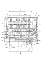
図4は、プリンター本体11を示す平面図である。
ところで、ドットインパクトプリンター10は、図4に示すように、記録媒体Saよりも大きな幅を有する記録媒体Sbや、記録媒体Sbよりも大きな幅を有する記録媒体Scを用いることも可能である。ここで、記録媒体Sbは、一例として、A4サイズの用紙であり、210(mm)の用紙幅を有し、記録媒体Scは、一例として、216(mm)の用紙幅を有するA4リーガルサイズよりも大きな幅を有する用紙である。記録媒体Sb及び記録媒体Scの表裏の面には表面スキャナー111及び裏面スキャナー112によって読み取られるべき情報がそれぞれ記録されている。
FIG. 4 is a plan view showing the printer main body 11.
Incidentally, as shown in FIG. 4, the dot impact printer 10 can also use a recording medium Sb having a larger width than the recording medium Sa and a recording medium Sc having a larger width than the recording medium Sb. Here, the recording medium Sb is an A4 size paper, for example, and has a paper width of 210 (mm), and the recording medium Sc is, for example, an A4 legal size having a paper width of 216 (mm). Is a sheet having a large width. Information to be read by the front surface scanner 111 and the back surface scanner 112 is recorded on the front and back surfaces of the recording medium Sb and the recording medium Sc, respectively.

搬送路Aに連通した手差口15には、手差口15の縁に連なって前方に略水平に突出した媒体挿入台60が設けられ、この媒体挿入台60の上面の媒体セット面60Aは、キャリッジ19(図3参照)の走行可能範囲に対応して幅広に形成され、主走査方向に沿って延在している。媒体セット面60Aは、手差口15に挿入される記録媒体を下方から支持し、記録媒体の挿入を安定させている。媒体セット面60Aの幅方向の両端には、媒体セット面60Aよりも上方に突出した段部62A、62Bがそれぞれ設けられている。これら段部62A、62Bの間の間隔である搬送範囲Wは手差口15の幅に一致し、手差口15に挿入して搬送機構100により搬送可能な記録媒体の最大幅を規定している。この搬送範囲Wの大きさ及び幅方向の位置は、キャリッジガイド軸31に沿って幅方向に走査される記録ヘッド18の記録可能範囲Pに一致している。ここでは、搬送範囲Wの幅、すなわち、手差口15の幅は、記録可能範囲Pに一致しているものとして説明したが、手差口15の幅は記録可能範囲Pの幅以上であっても良い。
また、媒体挿入台60の幅方向の左端側(一端側)に設けられた段部62Aは、記録媒体の幅方向の端を案内するガイドとして機能する。
The manual insertion slot 15 that communicates with the conveyance path A is provided with a medium insertion table 60 that continues to the edge of the manual insertion slot 15 and protrudes substantially horizontally forward. A medium setting surface 60A on the upper surface of the medium insertion table 60 is The carriage 19 (see FIG. 3) is formed in a wide width corresponding to the travelable range and extends along the main scanning direction. The medium setting surface 60A supports the recording medium inserted into the manual insertion slot 15 from below, and stabilizes the insertion of the recording medium. At both ends in the width direction of the medium setting surface 60A, step portions 62A and 62B are provided that protrude upward from the medium setting surface 60A. The conveyance range W, which is the distance between the stepped portions 62A and 62B, coincides with the width of the manual feed port 15 and defines the maximum width of the recording medium that can be inserted into the manual feed port 15 and conveyed by the conveyance mechanism 100. Yes. The size of the transport range W and the position in the width direction coincide with the recordable range P of the recording head 18 scanned in the width direction along the carriage guide shaft 31. Here, the width of the conveyance range W, that is, the width of the manual feed port 15 has been described as being coincident with the recordable range P. However, the width of the manual feed port 15 is equal to or greater than the width of the recordable range P. May be.
Further, the stepped portion 62A provided on the left end side (one end side) in the width direction of the medium insertion table 60 functions as a guide for guiding the end in the width direction of the recording medium.

媒体挿入台60には、記録媒体Sbの搬送方向に平行に延びる用紙ガイド61(幅規制部)が設けられている。用紙ガイド61は、媒体セット面60Aに立設された凸部であり、媒体挿入台60の幅方向の右端側(他端側)に位置している。用紙ガイド61の内側面は記録媒体を案内する案内面63となっている。
用紙ガイド61は、段部62Aとの間に所定の幅に設定された間隔Lをあけて配置されている。詳細には、間隔Lは、記録媒体Sbを案内可能なように記録媒体Sbの用紙幅よりも僅かに大きく形成されており、用紙ガイド61は、記録媒体Sbの挿入位置を左端側の段部62A寄りに規制している。また、間隔Lは搬送範囲Wよりも狭く形成されており、用紙ガイド61は、記録ヘッド18の記録可能範囲Pよりも狭い記録可能範囲の端位置に対応した位置に配置されている。すなわち、用紙ガイド61は、手差口15の幅を記録可能範囲Pの幅よりも小さい幅に規制している。
The medium insertion table 60 is provided with a paper guide 61 (width restricting portion) extending in parallel with the conveyance direction of the recording medium Sb. The paper guide 61 is a convex portion standing on the medium setting surface 60 </ b> A, and is located on the right end side (the other end side) in the width direction of the medium insertion table 60. The inner surface of the paper guide 61 is a guide surface 63 that guides the recording medium.
The sheet guide 61 is disposed with a gap L set to a predetermined width between the sheet guide 61 and the stepped portion 62A. Specifically, the interval L is formed to be slightly larger than the paper width of the recording medium Sb so that the recording medium Sb can be guided, and the paper guide 61 has a step portion on the left end side of the insertion position of the recording medium Sb. It is restricted to 62A. The interval L is formed narrower than the conveyance range W, and the paper guide 61 is disposed at a position corresponding to the end position of the recordable range narrower than the recordable range P of the recording head 18. In other words, the paper guide 61 regulates the width of the manual feed slot 15 to be smaller than the width of the recordable range P.

図4に示すように、ドットインパクトプリンター10の幅方向において、表面スキャナー111及び裏面スキャナー112の読取可能範囲T(読み取り可能範囲)の一端は、段部62Aの位置に一致し、読取可能範囲Tの他端は、用紙ガイド61における案内面63の位置に一致している。すなわち、用紙ガイド61は読取可能範囲Tに記録媒体Sbを案内する位置に設けられ、左端側の段部62A及び用紙ガイド61に案内されて搬送された記録媒体Sbは、必ず表面スキャナー111及び裏面スキャナー112の読取可能範囲T内に搬送されるため、確実に読み取りを行うことができる。また、記録媒体Saのような、記録媒体Sbよりも幅が狭い記録媒体の読み取りを行う場合においても、用紙ガイド61によって挿入位置が規制され、段部62Aと用紙ガイド61との間に記録媒体が挿入されるため、表面スキャナー111及び裏面スキャナー112の読取可能範囲T内に確実に記録媒体を搬送できる。   As shown in FIG. 4, in the width direction of the dot impact printer 10, one end of the readable range T (readable range) of the front surface scanner 111 and the rear surface scanner 112 coincides with the position of the stepped portion 62A. The other end coincides with the position of the guide surface 63 in the paper guide 61. That is, the paper guide 61 is provided at a position for guiding the recording medium Sb to the readable range T, and the recording medium Sb guided and conveyed by the left end side stepped portion 62A and the paper guide 61 is always the front scanner 111 and the back surface. Since it is conveyed within the readable range T of the scanner 112, it can be read reliably. Even when reading a recording medium having a width smaller than that of the recording medium Sb, such as the recording medium Sa, the insertion position is restricted by the paper guide 61, and the recording medium is interposed between the stepped portion 62 </ b> A and the paper guide 61. Therefore, the recording medium can be reliably conveyed within the readable range T of the front surface scanner 111 and the back surface scanner 112.

図5は、プリンター本体11の前部の側断面図である。
図5に示すように、用紙ガイド61は、側面視において略三角形の形状に形成されており、上方に突出した曲面状の頂部64Aと、頂部64Aから媒体セット面60Aまで前下がりに傾斜した前斜面部64Bと、頂部64Aから手差口15の奥側に向かって媒体セット面60Aまで傾斜した案内部64Cとを有している。この案内部64Cは、用紙ガイド61上を乗り越えて記録媒体を搬送可能とする斜面で構成される。
手差口15は、記録媒体が通過する通路部15Aと、通路部15Aの上端から用紙ガイド61の側へ前上がりに傾斜した導入部15Bとを有し、導入部15Bの上端は、頂部64Aよりも上方に位置している。
ドットインパクトプリンター10の前方側から手差口15に挿入される記録媒体Scは、先端が前斜面部64Bに乗り上げるようにして頂部64Aに達し、案内部64Cに沿うようにして下り、通路部15Aに挿入される。また、記録媒体Scが案内部64Cに完全に沿わなかった場合においても、案内部64Cの下流側に導入部15Bが設けられており、記録媒体Scの先端が導入部15Bに沿って通路部15Aに案内されるため、確実に記録媒体Scを挿入できる。
FIG. 5 is a side sectional view of the front portion of the printer main body 11.
As shown in FIG. 5, the paper guide 61 is formed in a substantially triangular shape in a side view, and has a curved top portion 64A that protrudes upward, and a front slope that is inclined downward from the top portion 64A to the medium setting surface 60A. A slope portion 64B and a guide portion 64C inclined from the top portion 64A to the medium setting surface 60A toward the back side of the manual feed port 15 are provided. The guide portion 64C is configured by a slope that allows the recording medium to be conveyed over the paper guide 61.
The manual feed opening 15 includes a passage portion 15A through which the recording medium passes, and an introduction portion 15B that is inclined upward from the upper end of the passage portion 15A toward the sheet guide 61. The upper end of the introduction portion 15B has a top portion 64A. It is located above.
The recording medium Sc inserted into the manual feed slot 15 from the front side of the dot impact printer 10 reaches the top part 64A so that the tip rides on the front slope part 64B, descends along the guide part 64C, and passes through the passage part 15A. Inserted into. Further, even when the recording medium Sc does not completely follow the guide portion 64C, the introduction portion 15B is provided on the downstream side of the guide portion 64C, and the leading end of the recording medium Sc extends along the introduction portion 15B to the passage portion 15A. Therefore, the recording medium Sc can be reliably inserted.

図4に示すように、ドットインパクトプリンター10は、読取可能範囲Tよりも幅広の記録可能範囲Pを有しており、間隔Lよりも大きな用紙幅を有する記録媒体Scは、手差口15に挿入された状態では、用紙ガイド61に重なることとなる。ドットインパクトプリンター10においては、用紙ガイド61が案内部64Cを有し、用紙ガイド61上を乗り越えるようにして記録媒体Scを搬送できるため、用紙ガイド61に重なる幅を有する記録媒体Scであってもスムーズに搬送できる。   As shown in FIG. 4, the dot impact printer 10 has a recordable range P wider than the readable range T, and a recording medium Sc having a paper width larger than the interval L is placed in the manual feed port 15. In the inserted state, it overlaps the paper guide 61. In the dot impact printer 10, since the paper guide 61 has the guide portion 64 </ b> C and can transport the recording medium Sc so as to get over the paper guide 61, even the recording medium Sc having a width overlapping the paper guide 61. It can be transported smoothly.

ここで、ドットインパクトプリンター10による記録媒体Sbの読み取り動作の概略を説明する。
まず、記録媒体Sbが左端側の段部62Aと用紙ガイド61との間に載置されるようにして手差口15に挿入されると、ドットインパクトプリンター10は媒体検出センサー47によって記録媒体Sbの挿入を検出し、第1駆動ローラー22Aを駆動する。
そして、記録媒体Sbは、第1駆動ローラー22A及び第1従動ローラー22Bにより搬送され、整列板28に対し先端部が突き当てられて整列され、第2駆動ローラー23A及び第2従動ローラー23Bによって、表面スキャナー111及び裏面スキャナー112の側に搬送される。この際、記録媒体Sbが段部62Aと用紙ガイド61とによって案内されるため、効果的に整列できる。さらに、整列動作時に用紙ガイド61によって記録媒体Sbの位置が規制され、記録媒体Sbが他端側の段部62Bの側に移動することが防止されるため、記録媒体Sbを確実に読取可能範囲T内に搬送できる。
表面スキャナー111と裏面スキャナー112との間に入り込んだ記録媒体Sbは、表面スキャナー111と裏面スキャナー112との間に狭持された状態で、搬送されながら連続的に表裏の面を読み取られる。読み取りが終了すると、搬送機構100は逆回転され、記録媒体Sbは段部62Aと用紙ガイド61との間を通って手差口15の側に排出される。
Here, an outline of the reading operation of the recording medium Sb by the dot impact printer 10 will be described.
First, when the recording medium Sb is inserted into the manual feed slot 15 so as to be placed between the step 62A on the left end side and the paper guide 61, the dot impact printer 10 is detected by the medium detection sensor 47 by the recording medium Sb. Is detected, and the first drive roller 22A is driven.
Then, the recording medium Sb is conveyed by the first driving roller 22A and the first driven roller 22B, aligned with the leading end abutting against the alignment plate 28, and by the second driving roller 23A and the second driven roller 23B. It is conveyed to the front scanner 111 and back scanner 112 side. At this time, since the recording medium Sb is guided by the stepped portion 62A and the paper guide 61, it can be effectively aligned. Further, the position of the recording medium Sb is regulated by the paper guide 61 during the alignment operation, and the recording medium Sb is prevented from moving to the stepped portion 62B on the other end side, so that the recording medium Sb can be reliably read. Can be transported within T.
The recording medium Sb that has entered between the front surface scanner 111 and the back surface scanner 112 is read between the front and back surfaces while being conveyed while being sandwiched between the front surface scanner 111 and the back surface scanner 112. When reading is completed, the transport mechanism 100 is rotated in the reverse direction, and the recording medium Sb passes between the stepped portion 62 </ b> A and the paper guide 61 and is discharged to the manual feed port 15 side.

次に、ドットインパクトプリンター10による記録媒体Scの記録動作の概略を説明する。
まず、記録媒体Scが段部62Aと段部62Bとの間に、用紙ガイド61を乗り越えるようにして挿入されると、ドットインパクトプリンター10は媒体検出センサー47によって記録媒体Scの挿入を検出し、第1駆動ローラー22Aを駆動する。
そして、記録媒体Scは、第1駆動ローラー22A及び第1従動ローラー22Bにより搬送され、整列板28に対し先端部が突き当てられて整列され、その後、記録ヘッド18により記録される。記録が終了すると、搬送機構100は逆回転され、記録媒体Scは手差口15の側に排出される。
Next, an outline of the recording operation of the recording medium Sc by the dot impact printer 10 will be described.
First, when the recording medium Sc is inserted between the stepped portion 62A and the stepped portion 62B so as to get over the paper guide 61, the dot impact printer 10 detects the insertion of the recording medium Sc by the medium detecting sensor 47, and The first drive roller 22A is driven.
Then, the recording medium Sc is conveyed by the first driving roller 22A and the first driven roller 22B, aligned with the leading end abutting against the alignment plate 28, and then recorded by the recording head 18. When the recording is completed, the transport mechanism 100 is rotated in the reverse direction, and the recording medium Sc is discharged to the manual feed port 15 side.

本第1の実施の形態では、媒体セット面60Aに用紙ガイド61を設けたため、記録媒体Sbを読取可能範囲T内に確実に搬送可能であり、さらに、用紙ガイド61に案内部64Cを設けたため、用紙ガイド61が記録媒体Scの搬送を妨げることが無く、記録媒体Sb或いは間隔Lより大きな用紙幅の記録媒体Scをスムーズに搬送することができる。
すなわち、ドットインパクトプリンター10では、記録媒体Sbのように読取可能範囲Tと同等の幅の記録媒体、或いは記録媒体Saのような読取可能範囲Tより幅狭の記録媒体を、表面スキャナー111及び裏面スキャナー112によって読み取る際には、用紙ガイド61によって手差口15の幅を規制して、記録媒体を確実に読取可能範囲T内に案内することができる。また、記録媒体Scのように読取可能範囲Tよりも幅広な記録媒体に記録ヘッド18による記録を行う場合には、用紙ガイド61を乗り越えて記録媒体を挿入することができる。
In the first embodiment, since the paper guide 61 is provided on the medium setting surface 60A, the recording medium Sb can be reliably conveyed within the readable range T, and the guide portion 64C is provided on the paper guide 61. The sheet guide 61 does not hinder the conveyance of the recording medium Sc, and the recording medium Sc having a sheet width larger than the interval L can be smoothly conveyed.
That is, in the dot impact printer 10, a recording medium having a width equivalent to the readable range T, such as the recording medium Sb, or a recording medium having a width narrower than the readable range T, such as the recording medium Sa, is used. When reading by the scanner 112, the width of the manual feed opening 15 is regulated by the paper guide 61, and the recording medium can be reliably guided within the readable range T. Further, when recording by the recording head 18 on a recording medium wider than the readable range T like the recording medium Sc, the recording medium can be inserted over the paper guide 61.

以上説明したように、本発明を適用した第1の実施の形態によれば、手差口15の幅が用紙ガイド61によって記録ヘッド18の記録可能範囲Pよりも小さい幅に規制されるため、記録可能範囲Pよりも小さい所望の範囲に記録媒体Sbを案内できる。さらに、用紙ガイド61が有する案内部64Cを乗り越えて記録媒体Scを挿入可能であるため、用紙ガイド61に手差口15の幅を規制されないようにして所望の位置に記録媒体Scを挿入することもできる。これにより、記録媒体が挿入される手差口15の所望の範囲に記録媒体を案内すると共に、この範囲を超える位置に記録媒体を挿入することもできる。
また、手差口15の幅が用紙ガイド61によって搬送機構100の搬送範囲Wよりも小さい幅に規制されるため、搬送範囲Wよりも小さい所望の範囲に記録媒体Sbを案内できる。さらに、用紙ガイド61が有する案内部64Cを乗り越えて記録媒体Scを挿入可能であるため、用紙ガイド61に手差口15の幅を規制されないようにして所望の位置に記録媒体Scを挿入することもできる。これにより、記録媒体が挿入される手差口15の所望の範囲に記録媒体を案内できると共に、この範囲を超える位置に記録媒体を挿入することもできる。
As described above, according to the first embodiment to which the present invention is applied, the width of the manual feed opening 15 is regulated by the paper guide 61 to be smaller than the recordable range P of the recording head 18. The recording medium Sb can be guided to a desired range smaller than the recordable range P. Furthermore, since the recording medium Sc can be inserted over the guide portion 64C of the paper guide 61, the recording medium Sc is inserted at a desired position so that the width of the manual feed opening 15 is not restricted by the paper guide 61. You can also. Accordingly, the recording medium can be guided to a desired range of the manual feed slot 15 into which the recording medium is inserted, and the recording medium can be inserted at a position exceeding this range.
In addition, since the width of the manual feed opening 15 is regulated to a width smaller than the conveyance range W of the conveyance mechanism 100 by the paper guide 61, the recording medium Sb can be guided to a desired range smaller than the conveyance range W. Furthermore, since the recording medium Sc can be inserted over the guide portion 64C of the paper guide 61, the recording medium Sc is inserted at a desired position so that the width of the manual feed opening 15 is not restricted by the paper guide 61. You can also. Thereby, the recording medium can be guided to a desired range of the manual feed slot 15 into which the recording medium is inserted, and the recording medium can be inserted at a position exceeding this range.

さらに、案内部64Cが手差口15の奥側に向かって下方に傾斜した斜面で構成され、記録媒体Scが斜面に沿うように案内されるため、記録媒体Scを用紙ガイド61を乗り越えて手差口15の奥側にスムーズに挿入できる。また、記録媒体Scが手差口15から排出される際に案内部64Cの斜面に沿うように排出されるため、記録媒体Scが用紙ガイド61に引っ掛かることが無く、記録媒体Scをスムーズに排出できる。
さらにまた、用紙ガイド61によって、手差口15の幅が表面スキャナー111及び裏面スキャナー112の読取可能範囲Tに合わせて規制され、記録媒体Sbが読取可能範囲Tに案内されるため、確実に記録媒体Sbの情報を読み取りできる。
また、整列動作が記録媒体Sbの後端が手差口15から突出する位置で行われ、整列の際に用紙ガイド61によって記録媒体Sbの移動可能な範囲が規制されるため、記録媒体Sbが整列動作の影響を受けて搬送されるべき位置からずれてしまうことを防止できる。
Further, since the guide portion 64C is configured with a slope inclined downward toward the back side of the manual feed slot 15, and the recording medium Sc is guided along the slope, the recording medium Sc is passed over the paper guide 61 and is handed. It can be smoothly inserted into the back side of the slot 15. Further, since the recording medium Sc is discharged along the inclined surface of the guide portion 64C when the recording medium Sc is discharged from the manual feed slot 15, the recording medium Sc is not caught by the paper guide 61, and the recording medium Sc is discharged smoothly. it can.
Furthermore, the width of the manual feed slot 15 is regulated by the paper guide 61 according to the readable range T of the front surface scanner 111 and the back surface scanner 112, and the recording medium Sb is guided to the readable range T, so that the recording is surely performed. Information on the medium Sb can be read.
Further, the alignment operation is performed at a position where the rear end of the recording medium Sb protrudes from the manual feed slot 15, and the movable range of the recording medium Sb is regulated by the paper guide 61 during the alignment. It is possible to prevent the shift from the position to be conveyed due to the influence of the alignment operation.

[第2の実施の形態]
以下、図5及び図6を参照して、本発明を適用した第2の実施の形態について説明する。この第2の実施の形態において、上記第1の実施の形態と同様に構成される部分については、同符号を付して説明を省略する。
第2の実施の形態は、上記第1の実施の形態における段部62Aの側に記録媒体の上面を案内する上面ガイド71を設け、この上面ガイド71に記録媒体を支持する支持部72を設けたものである。
[Second Embodiment]
Hereinafter, a second embodiment to which the present invention is applied will be described with reference to FIGS. 5 and 6. In the second embodiment, parts that are configured in the same manner as in the first embodiment are given the same reference numerals, and descriptions thereof are omitted.
In the second embodiment, an upper surface guide 71 for guiding the upper surface of the recording medium is provided on the side of the step portion 62A in the first embodiment, and a support portion 72 for supporting the recording medium is provided on the upper surface guide 71. It is a thing.

図6は、本発明の第2の実施の形態に係るドットインパクトプリンター70の正面図である。
図6に示すように、ドットインパクトプリンター70は、媒体挿入台60及び用紙ガイド61を備え、媒体挿入台60の左端側の段部62Aの側には、上方に突出した支持部72が設けられている。
支持部72は、段部62Aから媒体セット面60Aと平行に用紙ガイド61の側へ延びる板状の上面ガイド71を備え、上面ガイド71の上面に立設されている。この上面ガイド71は、媒体セット面60Aとの間に所定の高さの空間Uが確保されるように配置され、この空間Uの高さは、ドットインパクトプリンター70に挿入可能な記録媒体の内、最も板厚の厚い記録媒体が通過可能な高さに設定されている。すなわち、記録媒体は空間Uを通過可能であり、その上面を上面ガイド71によって案内されて搬送される。
段部62Aと上面ガイド71の先端との間の長さは、段部62Bから用紙ガイド61までの長さと同等である。
FIG. 6 is a front view of a dot impact printer 70 according to the second embodiment of the present invention.
As shown in FIG. 6, the dot impact printer 70 includes a medium insertion table 60 and a paper guide 61, and a support portion 72 that protrudes upward is provided on the left end side stepped portion 62 </ b> A of the medium insertion table 60. ing.
The support portion 72 includes a plate-like upper surface guide 71 extending from the stepped portion 62 </ b> A to the paper guide 61 side in parallel with the medium setting surface 60 </ b> A, and is erected on the upper surface of the upper surface guide 71. The upper surface guide 71 is disposed so as to ensure a space U having a predetermined height between the upper surface guide 71 and the medium setting surface 60 </ b> A. The height of the space U is within the recording medium that can be inserted into the dot impact printer 70. The height is set such that the thickest recording medium can pass through. That is, the recording medium can pass through the space U, and its upper surface is guided by the upper surface guide 71 and conveyed.
The length between the step portion 62A and the tip of the upper surface guide 71 is equal to the length from the step portion 62B to the paper guide 61.

図5に2点鎖線で示すように、支持部72は用紙ガイド61と同様に側面視で略三角形の形状に形成されている。支持部72は、上方に突出した曲面状の頂部74Aと、頂部74Aから上面ガイド71の上面71Aまで前下がりに傾斜した前斜面部74Bと、頂部74Aから手差口15の奥側に向かって上面71Aまで傾斜した第2の案内部74Cとを有している。第2の案内部74Cは、支持部72上を乗り越えて記録媒体を搬送可能とする斜面で構成される。
また、頂部74Aの高さは、用紙ガイド61の頂部64Aの高さと略等しい高さに位置している。なお、図5では、用紙ガイド61及び支持部72を示す線の重複を避けるために支持部72の輪郭線を用紙ガイド61の内側に示したが、支持部72と用紙ガイド61の上部とは、略同一形状かつ略同一高さである。
As indicated by a two-dot chain line in FIG. 5, the support portion 72 is formed in a substantially triangular shape in a side view like the paper guide 61. The support portion 72 has a curved top portion 74A that protrudes upward, a front slope portion 74B that slopes downward from the top portion 74A to the upper surface 71A of the upper surface guide 71, and from the top portion 74A toward the back side of the manual feed opening 15. A second guide portion 74C inclined to the upper surface 71A. The second guide portion 74C is configured by an inclined surface that allows the recording medium to be conveyed over the support portion 72.
Further, the height of the top portion 74 </ b> A is located at a height substantially equal to the height of the top portion 64 </ b> A of the paper guide 61. In FIG. 5, the outline of the support portion 72 is shown inside the paper guide 61 in order to avoid overlapping of the lines indicating the paper guide 61 and the support portion 72, but the support portion 72 and the upper portion of the paper guide 61 are different from each other. , Approximately the same shape and approximately the same height.

ここで、ドットインパクトプリンター70による記録媒体Sbの読み取り動作の概略を説明する。
まず、記録媒体Sbが、段部62Aと用紙ガイド61との間に挿入されると共に、上面ガイド71と媒体セット面60Aとの間に通されると、ドットインパクトプリンター70は媒体検出センサー47によって記録媒体Sbの挿入を検出し、第1駆動ローラー22Aを駆動する。
そして、記録媒体Sbは、第1駆動ローラー22A及び第1従動ローラー22Bにより搬送され、整列板28に対し先端部が突き当てられて整列され、第2駆動ローラー23A及び第2従動ローラー23Bによって、表面スキャナー111及び裏面スキャナー112の側に搬送されて読み取られる。この際、用紙ガイド61によって記録媒体Sbの位置が規制されるため、記録媒体Sbを確実に読取可能範囲T内に搬送でき、さらに、記録媒体Sbの上面の位置を上面ガイド71によって規制できるため、記録媒体Sbの浮き上がりを防止でき、スムーズに搬送できる。
読み取りが終了すると、搬送機構100は逆回転され、記録媒体Sbは、段部62Aと用紙ガイド61との間を通りつつ、上面ガイド71に上面を案内されて手差口15の側に排出される。
Here, an outline of the reading operation of the recording medium Sb by the dot impact printer 70 will be described.
First, when the recording medium Sb is inserted between the step portion 62A and the paper guide 61 and passed between the upper surface guide 71 and the medium setting surface 60A, the dot impact printer 70 is detected by the medium detection sensor 47. The insertion of the recording medium Sb is detected, and the first drive roller 22A is driven.
Then, the recording medium Sb is conveyed by the first driving roller 22A and the first driven roller 22B, aligned with the leading end abutting against the alignment plate 28, and by the second driving roller 23A and the second driven roller 23B. It is conveyed to the side of the front surface scanner 111 and the back surface scanner 112 and read. At this time, since the position of the recording medium Sb is regulated by the paper guide 61, the recording medium Sb can be reliably conveyed within the readable range T, and further, the position of the upper surface of the recording medium Sb can be regulated by the upper surface guide 71. In addition, the recording medium Sb can be prevented from being lifted, and can be smoothly conveyed.
When the reading is completed, the transport mechanism 100 is rotated in the reverse direction, and the recording medium Sb is guided between the upper surface guide 71 and discharged to the manual feed port 15 side while passing between the stepped portion 62A and the paper guide 61. The

次に、ドットインパクトプリンター70による記録媒体Scの記録動作の概略を説明する。
まず、記録媒体Scは、用紙ガイド61及び支持部72上に載置され、頂部64A、74Aの間に掛け渡されるようにしてセットされる。ドットインパクトプリンター70は媒体検出センサー47によって記録媒体Scの挿入を検出し、第1駆動ローラー22Aを駆動する。
そして、記録媒体Scは、第1駆動ローラー22A及び第1従動ローラー22Bよって、用紙ガイド61及び支持部72を乗り越えるようにして搬送され、整列板28に対し先端部が突き当てられて整列され、その後、記録ヘッド18により記録される。記録が終了すると、搬送機構100は逆回転され、記録媒体Scは空間U及び案内部64Cを経て手差口15の側に排出される。
Next, an outline of the recording operation of the recording medium Sc by the dot impact printer 70 will be described.
First, the recording medium Sc is placed on the paper guide 61 and the support portion 72, and is set so as to be spanned between the top portions 64A and 74A. The dot impact printer 70 detects the insertion of the recording medium Sc by the medium detection sensor 47 and drives the first drive roller 22A.
Then, the recording medium Sc is conveyed by the first drive roller 22A and the first driven roller 22B so as to get over the paper guide 61 and the support portion 72, and the leading end is abutted against the alignment plate 28 and aligned. Thereafter, recording is performed by the recording head 18. When the recording is completed, the transport mechanism 100 is rotated in the reverse direction, and the recording medium Sc is discharged to the manual feed port 15 side through the space U and the guide portion 64C.

本第2の実施の形態では、用紙ガイド61に加えて、媒体挿入台60の左端側に案内部64Cと略同一高さを有する支持部72を設けて、記録媒体Scの幅方向の両端部をそれぞれ支持するため、記録媒体Scを略水平に保った状態で搬送でき、記録媒体Scをスムーズに、かつ、真直ぐに搬送できる。
また、支持部72を上面ガイド71に立設し、支持部72及び上面ガイド71の下方に記録媒体Sbを挿入可能な空間Uを確保したため、記録媒体Scを略水平に支持して支持部72を乗り越えて搬送可能でありながら、記録媒体Sbの挿入スペースを確保し、記録媒体Sbの挿入位置を用紙ガイド61で規制可能な構造を実現できる。
In the second embodiment, in addition to the paper guide 61, a support portion 72 having substantially the same height as the guide portion 64C is provided on the left end side of the medium insertion base 60, and both end portions in the width direction of the recording medium Sc. Therefore, the recording medium Sc can be transported in a substantially horizontal state, and the recording medium Sc can be transported smoothly and straight.
Further, since the support portion 72 is erected on the upper surface guide 71 and the space U into which the recording medium Sb can be inserted is secured below the support portion 72 and the upper surface guide 71, the support portion 72 supports the recording medium Sc substantially horizontally. However, it is possible to secure a space for inserting the recording medium Sb and to control the insertion position of the recording medium Sb with the paper guide 61.

以上説明したように、本発明を適用した第2の実施の形態によれば、手差口15の幅方向の右端側に用紙ガイド61を設け、左端側に用紙ガイド61の案内部64Cと略同一高さで記録媒体Scが乗り越え可能な支持部72を設けたため、記録媒体Scを幅方向に渡って同一高さで支持でき、記録媒体Scを略水平な状態で案内できる。このため、記録媒体Scをスムーズに搬送できる。
また、上面ガイド71によって記録媒体Sbを上方から押さえるため、記録媒体Sbの浮き上がりを防止できる。さらに、支持部72の下方の空間Uを通して記録媒体Sbを挿入できるため、手差口15の幅に影響を及ぼすことなく支持部72を設けることができ、手差口15の幅を大きくできる。従って、上面ガイド71及び支持部72の下方を通して記録媒体Sbを挿入できると共に、支持部72を乗り越えるようにして記録媒体Scを挿入することもできる。
As described above, according to the second embodiment to which the present invention is applied, the paper guide 61 is provided on the right end side of the manual feed port 15 in the width direction, and the guide portion 64C of the paper guide 61 is substantially provided on the left end side. Since the support portion 72 on which the recording medium Sc can get over at the same height is provided, the recording medium Sc can be supported at the same height in the width direction, and the recording medium Sc can be guided in a substantially horizontal state. For this reason, the recording medium Sc can be smoothly conveyed.
Further, since the recording medium Sb is pressed from above by the upper surface guide 71, the recording medium Sb can be prevented from being lifted. Furthermore, since the recording medium Sb can be inserted through the space U below the support portion 72, the support portion 72 can be provided without affecting the width of the manual feed port 15, and the width of the manual feed port 15 can be increased. Accordingly, the recording medium Sb can be inserted through the upper surface guide 71 and the support portion 72, and the recording medium Sc can be inserted so as to get over the support portion 72.

以上、本発明の実施の形態について説明したが、本発明は、上記第1の実施の形態及び上記第2の実施の形態に限定されない。
上記実施の形態では、用紙ガイド61を、媒体挿入台60の幅方向の右端側に設けるもとして説明したが、本発明はこれに限定されるものではなく、用紙ガイドを媒体挿入台60の幅方向に複数設けても良い。例えば、用紙ガイド61に加え、用紙ガイド61よりも媒体挿入台60の中央側に用紙ガイド61よりも高さが低い用紙ガイドを設けても良い。
また、上記実施の形態では、用紙ガイド61は、読取可能範囲Tに記録媒体Sbを案内する位置に設けられるものとして説明したが、本発明はこれに限定されるものではなく、例えば、ドットインパクトプリンター10が表面スキャナー111及び裏面スキャナー112を有していない構成において、用紙ガイド61を、記録ヘッド18の記録可能範囲P内において記録可能範囲Pよりも狭い範囲に記録媒体Sbを案内する位置に設けても良い。この場合においても、記録媒体Sbの挿入位置を規制できると共に、用紙ガイド61を乗り越えて記録媒体Scを搬送することもできる。
As mentioned above, although embodiment of this invention was described, this invention is not limited to the said 1st Embodiment and the said 2nd Embodiment.
In the above embodiment, the paper guide 61 is described as being provided on the right end side in the width direction of the medium insertion table 60, but the present invention is not limited to this, and the paper guide is arranged in the width of the medium insertion table 60. A plurality may be provided in the direction. For example, in addition to the paper guide 61, a paper guide having a height lower than that of the paper guide 61 may be provided on the center side of the medium insertion table 60 relative to the paper guide 61.
In the above embodiment, the paper guide 61 is described as being provided at a position where the recording medium Sb is guided to the readable range T. However, the present invention is not limited to this, and for example, dot impact In the configuration in which the printer 10 does not include the front surface scanner 111 and the back surface scanner 112, the paper guide 61 is positioned to guide the recording medium Sb to a range narrower than the recordable range P within the recordable range P of the recording head 18. It may be provided. Even in this case, the insertion position of the recording medium Sb can be restricted, and the recording medium Sc can be transported over the paper guide 61.

また、上記実施の形態では、用紙ガイド61は、表面スキャナー111及び裏面スキャナー112の読取可能範囲Tに記録媒体Sbを案内する位置に設けられるものとして説明したが、これに限らず、用紙ガイド61は他の読取装置の読取可能範囲に合わせて設けても良く、例えば、磁気ヘッド34の読取可能範囲に記録媒体を案内する位置に用紙ガイド61を設けても良い。
さらに、本発明はドットインパクト式のプリンターに限らず、インクジェット式のプリンターや、感熱媒体を加熱して画像を記録するサーマルプリンターにおいても適用可能である。さらに、ドットインパクトプリンター10のように独立したプリンターとして使用される機器に限らず、他の機器(ATM(Automated Teller Machine)やCD(Cash Dispenser)等)に組み込まれたものであってもよく、多様な機器に適用可能である。
In the above embodiment, the paper guide 61 is described as being provided at a position for guiding the recording medium Sb to the readable range T of the front surface scanner 111 and the back surface scanner 112. However, the present invention is not limited to this, and the paper guide 61 is not limited thereto. May be provided in accordance with the readable range of another reading device. For example, a paper guide 61 may be provided at a position where the recording medium is guided to the readable range of the magnetic head 34.
Furthermore, the present invention is not limited to a dot impact type printer, but can also be applied to an ink jet type printer or a thermal printer that records an image by heating a thermal medium. Furthermore, it is not limited to a device used as an independent printer such as the dot impact printer 10, but may be incorporated in other devices (ATM (Automated Teller Machine), CD (Cash Displacer), etc.) Applicable to various devices.

10、70…ドットインパクトプリンター(記録装置)、15…手差口(挿入口)、18…記録ヘッド(記録部)、30…整列機構、61…用紙ガイド(幅規制部)、64A…頂部、64C…案内部、71…上面ガイド、72…支持部、74C…第2の案内部、100…搬送機構(搬送部)、111…表面スキャナー(読取部)、112…裏面スキャナー(読取部)、P…記録可能範囲、Sa…記録媒体、Sb…記録媒体、Sc…記録媒体、T…読取可能範囲(読み取り可能範囲)、W…搬送範囲。   DESCRIPTION OF SYMBOLS 10, 70 ... Dot impact printer (recording apparatus), 15 ... Manual feed port (insertion port), 18 ... Recording head (recording part), 30 ... Alignment mechanism, 61 ... Paper guide (width regulation part), 64A ... Top part, 64C ... guide unit, 71 ... upper surface guide, 72 ... support unit, 74C ... second guide unit, 100 ... conveying mechanism (conveying unit), 111 ... front surface scanner (reading unit), 112 ... back surface scanner (reading unit), P ... recordable range, Sa ... recording medium, Sb ... recording medium, Sc ... recording medium, T ... readable range (readable range), W ... transport range.

Claims (7)

記録媒体に記録を行う記録部を備えた記録装置において、
前記記録部により記録可能な範囲として定められた記録可能範囲以上の幅を有する挿入口を有し、
前記挿入口の幅を、前記記録可能範囲よりも小さい幅に規制する幅規制部を備え、
前記幅規制部は、該幅規制部を乗り越えて前記記録媒体を前記挿入口に挿入可能とする案内部を有すること、
を特徴とする記録装置。
In a recording apparatus having a recording unit for recording on a recording medium,
Having an insertion slot having a width equal to or larger than a recordable range determined as a recordable range by the recording unit;
A width restricting portion for restricting the width of the insertion port to a width smaller than the recordable range;
The width restricting portion has a guide portion that allows the recording medium to be inserted into the insertion port over the width restricting portion;
A recording apparatus.
記録媒体に記録を行う記録部と、前記記録媒体を挿入する挿入口と、前記挿入口から挿入された前記記録媒体を搬送する搬送部とを備え、
前記挿入口は、前記搬送部によって前記記録媒体が搬送される搬送範囲に対応した幅を有する開口であり、
前記挿入口において前記記録媒体を挿入可能な幅を、より小さい幅に規制する幅規制部を備え、
前記幅規制部は、該幅規制部を乗り越えて前記記録媒体を前記挿入口に挿入可能とする案内部を有すること、
を特徴とする記録装置。
A recording unit for recording on a recording medium, an insertion port for inserting the recording medium, and a transport unit for transporting the recording medium inserted from the insertion port,
The insertion port is an opening having a width corresponding to a conveyance range in which the recording medium is conveyed by the conveyance unit,
A width restricting portion for restricting a width into which the recording medium can be inserted into the insertion port to a smaller width;
The width restricting portion has a guide portion that allows the recording medium to be inserted into the insertion port over the width restricting portion;
A recording apparatus.
前記挿入口の縁に連なり、前記挿入口に進入する記録媒体を支持する媒体挿入台を設け、
前記幅規制部は、前記媒体挿入台に立設された凸部であり、
前記案内部は、前記幅規制部の頂部から前記挿入口の奥側に向かって下方に傾斜する斜面で構成されること、
を特徴とする請求項2記載の記録装置。
Provided with a medium insertion table that is connected to the edge of the insertion slot and supports a recording medium that enters the insertion slot;
The width restricting portion is a convex portion erected on the medium insertion table,
The guide portion is configured by a slope that is inclined downward from the top of the width regulating portion toward the back side of the insertion port,
The recording apparatus according to claim 2.
前記挿入口から挿入された前記記録媒体の表面を光学的に読み取る読取部を備え、
前記幅規制部は、前記挿入口において前記記録媒体を挿入可能な幅を、前記読取部の読み取り可能範囲に合わせて規制すること、
を特徴とする請求項2または3記載の記録装置。
A reading unit that optically reads the surface of the recording medium inserted from the insertion port;
The width restricting portion restricts a width in which the recording medium can be inserted in the insertion port according to a readable range of the reading portion;
The recording apparatus according to claim 2, wherein the recording apparatus is a recording apparatus.
前記挿入口から挿入された前記記録媒体の向きを、前記搬送部による搬送方向に沿って整える整列機構を備え、
前記整列機構は、前記記録媒体の後端が前記挿入口から突出する位置で前記記録媒体の向きを整えること、
を特徴とする請求項2から4のいずれかに記載の記録装置。
An alignment mechanism for adjusting the direction of the recording medium inserted from the insertion port along the transport direction by the transport unit;
The alignment mechanism adjusts the orientation of the recording medium at a position where the rear end of the recording medium protrudes from the insertion port;
The recording apparatus according to claim 2, wherein:
前記幅規制部を前記挿入口の幅方向の一端側に設け、
前記挿入口の他端側に、前記幅規制部の前記案内部と略同一高さで前記記録媒体が乗り越え可能な支持部を設けたこと、
を特徴とする請求項2から5のいずれかに記載の記録装置。
The width restricting portion is provided on one end side in the width direction of the insertion port,
Provided on the other end side of the insertion port is a support portion on which the recording medium can get over at substantially the same height as the guide portion of the width restricting portion;
The recording apparatus according to claim 2, wherein:
前記支持部の下方には、前記搬送部によって搬送される前記記録媒体が通過可能な空間が形成され、
前記支持部は、前記空間を通過する前記記録媒体の上方から前記記録媒体を押さえる上面ガイドを備えること、
を特徴とする請求項6に記載の記録装置。
A space through which the recording medium transported by the transport section can pass is formed below the support section.
The support portion includes an upper surface guide for pressing the recording medium from above the recording medium passing through the space;
The recording apparatus according to claim 6.
JP2009177436A 2009-07-30 2009-07-30 Recorder Withdrawn JP2011032003A (en)

Priority Applications (1)

Application Number Priority Date Filing Date Title
JP2009177436A JP2011032003A (en) 2009-07-30 2009-07-30 Recorder

Applications Claiming Priority (1)

Application Number Priority Date Filing Date Title
JP2009177436A JP2011032003A (en) 2009-07-30 2009-07-30 Recorder

Publications (1)

Publication Number Publication Date
JP2011032003A true JP2011032003A (en) 2011-02-17

Family

ID=43761472

Family Applications (1)

Application Number Title Priority Date Filing Date
JP2009177436A Withdrawn JP2011032003A (en) 2009-07-30 2009-07-30 Recorder

Country Status (1)

Country Link
JP (1) JP2011032003A (en)

Citations (4)

* Cited by examiner, † Cited by third party
Publication number Priority date Publication date Assignee Title
JPS53131111A (en) * 1977-04-21 1978-11-15 Fujitsu Ltd Dual front inserter
JPH0325455U (en) * 1989-07-24 1991-03-15
JP3000608U (en) * 1994-01-31 1994-08-09 船井電機株式会社 Paper introduction mechanism
JP2002321838A (en) * 2001-02-23 2002-11-08 Canon Inc Paper feeding device and recording device provided with the same

Patent Citations (4)

* Cited by examiner, † Cited by third party
Publication number Priority date Publication date Assignee Title
JPS53131111A (en) * 1977-04-21 1978-11-15 Fujitsu Ltd Dual front inserter
JPH0325455U (en) * 1989-07-24 1991-03-15
JP3000608U (en) * 1994-01-31 1994-08-09 船井電機株式会社 Paper introduction mechanism
JP2002321838A (en) * 2001-02-23 2002-11-08 Canon Inc Paper feeding device and recording device provided with the same

Similar Documents

Publication Publication Date Title
JP4396727B2 (en) Guide device and image recording device
JP2011146835A (en) Optical reader, method of controlling the same, and program
US7618035B2 (en) Image recording apparatus
JP5369968B2 (en) Alignment / conveyance apparatus, control method for alignment / conveyance apparatus, and recording apparatus
JP2012025078A (en) Information reading and printing apparatus, control method for the information reading and printing apparatus, and control program
US8218158B2 (en) Sheet processing apparatus
JP2011032004A (en) Optical reader and recorder
JP2012162035A (en) Recording apparatus, and method for controlling the same
JP5282509B2 (en) Sheet detecting apparatus and image recording apparatus
JP2011032003A (en) Recorder
JP2007137035A (en) Control method of print medium processor and print medium processor
JP2007230721A (en) Recorder and control method of recorder
JP6987665B2 (en) Transport and recording equipment
JP4735383B2 (en) Recording apparatus and method for controlling recording apparatus
JP2009223947A (en) Recording device and method for controlling the same
JP5018389B2 (en) Recording apparatus and recording apparatus control method
JP7113640B2 (en) Image scanner adapters and image scanners
JP2010116225A (en) Recording device and method for controlling recording device
JP2011035502A (en) Optical reader
JP4089536B2 (en) Printer
JP5861253B2 (en) Recording apparatus and method for controlling recording apparatus
JP2007230071A (en) Recording device and method of controlling recording device
JP2009161314A (en) Recorder and aligning mechanism thereof
JP2006248100A (en) Recorder
JP2007160592A (en) Recorder

Legal Events

Date Code Title Description
A621 Written request for application examination

Free format text: JAPANESE INTERMEDIATE CODE: A621

Effective date: 20120301

A977 Report on retrieval

Free format text: JAPANESE INTERMEDIATE CODE: A971007

Effective date: 20130527

A131 Notification of reasons for refusal

Free format text: JAPANESE INTERMEDIATE CODE: A131

Effective date: 20130604

A761 Written withdrawal of application

Free format text: JAPANESE INTERMEDIATE CODE: A761

Effective date: 20130730