JP2011031237A - Method for improving activity of denitrification catalyst in flue gas denitrification apparatus - Google Patents
Method for improving activity of denitrification catalyst in flue gas denitrification apparatus Download PDFInfo
- Publication number
- JP2011031237A JP2011031237A JP2010038145A JP2010038145A JP2011031237A JP 2011031237 A JP2011031237 A JP 2011031237A JP 2010038145 A JP2010038145 A JP 2010038145A JP 2010038145 A JP2010038145 A JP 2010038145A JP 2011031237 A JP2011031237 A JP 2011031237A
- Authority
- JP
- Japan
- Prior art keywords
- catalyst
- water
- flue gas
- catalytic activity
- acid
- Prior art date
- Legal status (The legal status is an assumption and is not a legal conclusion. Google has not performed a legal analysis and makes no representation as to the accuracy of the status listed.)
- Granted
Links
Images


Landscapes
- Catalysts (AREA)
Abstract
【課題】 本発明では、シリカ・アルミナ・硫酸カルシウム系の被毒物質で活性が低下した脱硝触媒の活性の回復方法を提供することを目的とするものである。
【解決手段】 シリカ・アルミナ・硫酸カルシウム系の被毒物質で活性が低下した脱硝触媒を予め水洗いし、含水させた後に有機酸とフッ化水素酸との混酸を用いて同物質を常温で洗浄除去することを特徴とし、上記混酸の有機酸がシュウ酸又はクエン酸であって、活性が低下した脱硝触媒に上記混酸をかけ流した後、又は上記混酸を入れたタンクに脱硝触媒を所定時間浸漬し引き上げた後、触媒底部から送風して水切りを行うことを特徴とする触媒活性の改良方法。
【選択図】 図2PROBLEM TO BE SOLVED: To provide a method for recovering the activity of a denitration catalyst whose activity has been reduced by a silica / alumina / calcium sulfate-based poisoning substance.
SOLUTION: A denitration catalyst whose activity has been reduced by a silica / alumina / calcium sulfate-based poisoning substance is washed with water in advance, and after hydration, the substance is washed at room temperature using a mixed acid of an organic acid and hydrofluoric acid. The mixed acid is oxalic acid or citric acid, and the mixed acid is poured over the denitration catalyst whose activity has been reduced, or the denitration catalyst is placed in a tank containing the mixed acid for a predetermined time. A method for improving catalytic activity, comprising: dipping and pulling up, then blowing air from the bottom of the catalyst to drain water.
[Selection] Figure 2
Description
本発明は、ボイラー等の排ガスに使用する排煙脱硝装置において、被毒物質が触媒に蓄積し、それによって活性が低下した脱硝触媒の活性の改良方法に関するものである。 The present invention relates to a method for improving the activity of a denitration catalyst in which poisonous substances accumulate in the catalyst in the flue gas denitration apparatus used for exhaust gas such as boilers and the activity is thereby reduced.
近年の石炭性状の多様化や運用形態の変化も加わり、触媒表面にシリカ・アルミナ・硫酸カルシウム系の被毒物質の緻密なコート層を形成し、従来の触媒の再生工法では上記被毒物質が十分に除去されないケースが見られるようになってきている。 With the recent diversification of coal properties and changes in operational forms, a dense coating layer of silica / alumina / calcium sulfate-based poisonous substances is formed on the catalyst surface. Cases that are not sufficiently removed have been seen.
シリカ系の被毒物質で性能低下した脱硝触媒の再生方法として、洗浄液中のフッ化水素酸の濃度を0.3〜3重量%とし、溶解除去力高めるために洗浄液温を40〜80℃に維持する方法が用いられた(特許文献1)。 As a method of regenerating a denitration catalyst whose performance has deteriorated due to a silica-based poisonous substance, the concentration of hydrofluoric acid in the cleaning liquid is set to 0.3 to 3% by weight, and the cleaning liquid temperature is set to 40 to 80 ° C. in order to increase dissolution and removal power A maintenance method was used (Patent Document 1).
一般的にフッ化水素酸はシリカに対して著しく溶解除去力が高いことが知られている。
フッ化水素酸は、濃度を高くすれば被毒物質の溶解除去力が増す反面、副作用として触媒強度を低下させる問題がある。
又フッ化水素酸で活性が低下した触媒を直接洗うと、溶解除去力が大きいことから被毒物質の溶解除去だけでなく、触媒成分のバナジウムやタングステンも溶出し、反って性能回復が悪くなることがある。さらに、フッ化水素酸の液温を高めると低濃度でも溶解力が大きくなり、前述の触媒強度低下を助長する恐れがある。
In general, hydrofluoric acid is known to have an extremely high ability to dissolve and remove silica.
Hydrofluoric acid increases the ability to dissolve and remove poisonous substances if the concentration is increased, but has a problem of reducing the catalyst strength as a side effect.
In addition, when a catalyst whose activity has been lowered with hydrofluoric acid is washed directly, the ability to dissolve and remove is large, so that not only the poisoning substance is dissolved and removed, but also the catalyst components vanadium and tungsten are eluted, and the performance recovery is worsened. Sometimes. Further, when the liquid temperature of hydrofluoric acid is increased, the dissolving power increases even at a low concentration, which may promote the above-described decrease in catalyst strength.
又触媒には、被毒物質のシリカ以外にフッ化水素酸と反応して難溶性の化合物を生成するカルシウム成分も含まれており、同化合物が被毒物質のコート層に沈着した場合、シリカの溶解除去を阻害する問題がある。 In addition to the poisoning substance silica, the catalyst also contains a calcium component that reacts with hydrofluoric acid to form a poorly soluble compound. When this compound is deposited on the poisoning substance coating layer, There is a problem that hinders the dissolution and removal of sucrose.
一方、触媒は多孔質であり、その乾燥重量の2〜3割相当の吸水能力がある。
このため、そのままで触媒の洗浄に入ると、洗浄液の消費量が甚だしいだけではなく、必要でない触媒の構成素材内部にまで洗浄液中のフッ化水素酸が浸入し、触媒強度の維持に必要な無機繊維中のシリカの溶解による触媒強度の低下の原因となる。
On the other hand, the catalyst is porous and has a water absorption capacity corresponding to 20 to 30% of its dry weight.
For this reason, when the catalyst cleaning is started as it is, not only is the consumption of the cleaning liquid excessive, but also hydrofluoric acid in the cleaning liquid penetrates into the unnecessary constituent material of the catalyst, and the inorganic necessary for maintaining the catalyst strength. It causes a decrease in catalyst strength due to dissolution of silica in the fiber.
又被毒物質の組成に近い物質を含む燃焼灰も付着しており、フッ化水素酸がこれらの溶解にも費やされるので、予め洗浄液中のフッ化水素酸濃度を高めておかないと溶解除去力の不足につながる。 Combustion ash containing substances close to the composition of poisonous substances is also attached, and hydrofluoric acid is also used to dissolve these substances. Therefore, if the concentration of hydrofluoric acid in the cleaning liquid is not increased in advance, it will be dissolved and removed. It leads to lack of power.
現行の触媒活性の改良工法では、繰り返し施工した場合や長期使用で著しく活性が低下している触媒で再生率が低下し、洗浄時間を長くしないと十分な効果が得られなくなるケースがある。
洗浄時間の延長は、施工期間の延長につながるため、工期の面から触媒活性改良工法の適用が困難になることも考えられる。
この原因は、次の1、2、3であることを突き止めた。
1.シリカ・アルミナ・硫酸カルシウム系の被毒物質のコート層が運用条件によっては緻密化し、難溶化する。
2.シリカ・アルミナ・硫酸カルシウム系の被毒物質のコート層の中でシリカ成分の除去が不十分となる。
3.再生によるシリカ・アルミナ・硫酸カルシウム系の被毒物質のコート層が十分除去できないと触媒成分を追加付着させても性能回復させなければならない。
本発明では、シリカ・アルミナ・硫酸カルシウム系の被毒物質で活性が低下した脱硝触媒の活性の回復方法を提供することを目的とするものである。
In the current method for improving the catalytic activity, there are cases where the regeneration rate is lowered with a catalyst that has been repeatedly applied or has been significantly reduced in long-term use, and a sufficient effect cannot be obtained unless the washing time is lengthened.
Since the extension of the cleaning time leads to the extension of the construction period, it may be difficult to apply the catalytic activity improvement method from the viewpoint of construction period.
The cause was as follows 1, 2, and 3.
1. Depending on the operating conditions, the silica / alumina / calcium sulfate-based poisoning layer becomes dense and hardly soluble.
2. Removal of the silica component is insufficient in the coating layer of the silica / alumina / calcium sulfate based poisoning substance.
3. If the coating layer of silica, alumina, and calcium sulfate-based poisoning substances due to regeneration cannot be removed sufficiently, performance must be restored even if additional catalyst components are deposited.
It is an object of the present invention to provide a method for recovering the activity of a denitration catalyst whose activity has been reduced by a silica / alumina / calcium sulfate-based poisoning substance.
上記の目的を達成するため本発明は
第1にボイラー等の排ガスに使用する排煙脱硝装置における触媒活性改良方法において、シリカ・アルミナ・硫酸カルシウム系の被毒物質で活性が低下した脱硝触媒を予め水洗いし、含水させた後に有機酸とフッ化物との混液を用いて同物質を常温で洗浄除去することを特徴とする排煙脱硝装置における触媒活性改良方法、
第2に上記混液の有機酸がシュウ酸又はクエン酸である上記第1発明記載の排煙脱硝装置における触媒活性改良方法、
第3に上記混液のフッ化物がフッ化水素酸又は水溶性フッ化物塩である上記第1発明記載の排煙脱硝装置における触媒活性改良方法、
第4に活性が低下した上記脱硝触媒に上記混液をかけ流した後、引き上げて水切りした後、フッ化物を後工程に持ち込まないように付着混液を水又は希薄な有機酸でリンスし、さらに触媒成分を含む水溶液でリンスして洗い流した後、触媒底部から送風して水切りを行うことを特徴とする上記第1〜第3発明の何れかに記載の排煙脱硝装置における触媒活性改良方法、
第5に上記触媒成分がバナジウム化合物とタングステン化合物である上記第4発明記載の排煙脱硝装置における触媒活性改良方法、
第6に上記混液の槽中に上記触媒を浸漬し、該触媒上部に設置したポンプで上記混液を該触媒底部から吸引し循環流動させた後、引き上げて水切りした後、上記フッ化物を後工程に持ち込まないように付着混液を水又は希薄な有機酸でリンスして洗い流した後、該触媒の底部から送風して水切りを行うことを特徴とする上記第1〜第3発明のいずれかに記載の排煙脱硝装置における触媒活性改良方法、
第7に触媒上部から、混液をシャワーノズルで散布し、触媒底部から流れ出る混液を回収し、ポンプで汲み上げてシャワーノズルに供給して循環洗浄後、引き上げて水切りした後、フッ化物を後工程に持ち込まないように付着混液を水又は希薄な有機酸でリンスし、さらに触媒成分を含む水溶液でリンスして洗い流した後、同触媒の底部から送風して水切りを行うことを特徴とする上記第1〜第4発明のいずれかに記載の排煙脱硝装置における触媒活性改良方法、
によって構成される。
In order to achieve the above object, the present invention provides a method for improving the catalytic activity of a flue gas denitration apparatus used for exhaust gas from a boiler or the like. A method for improving the catalytic activity in a flue gas denitrification apparatus, wherein the substance is washed and removed in advance and washed with water at room temperature using a mixture of an organic acid and a fluoride.
Second, the method for improving the catalytic activity in the flue gas denitrification device according to the first invention, wherein the organic acid in the mixed solution is oxalic acid or citric acid,
Third, the catalyst activity improving method in the flue gas denitrification apparatus according to the first invention, wherein the fluoride of the mixed solution is hydrofluoric acid or a water-soluble fluoride salt,
Fourth, after pouring the mixed solution over the denitration catalyst having reduced activity, draining and draining, the adhering mixed solution is rinsed with water or dilute organic acid so that the fluoride is not brought into the subsequent process, and further the catalyst The method for improving catalytic activity in a flue gas denitration device according to any one of the first to third inventions, wherein the water is exhausted by rinsing and washing with an aqueous solution containing components and then blown from the bottom of the catalyst.
Fifthly, the catalyst activity improving method in the flue gas denitrification apparatus according to the fourth invention, wherein the catalyst components are a vanadium compound and a tungsten compound,
Sixth, the catalyst is immersed in the tank of the mixed solution, and the mixed solution is sucked from the bottom of the catalyst by a pump installed on the top of the catalyst and circulated and then drained, drained, and then the fluoride is subjected to a post-process. In any one of the first to third aspects of the present invention, the adhering mixture is rinsed with water or a dilute organic acid so as not to be brought into the water and washed away, and then blown from the bottom of the catalyst to drain the water. Method for improving catalytic activity in flue gas denitration equipment,
Seventh, the mixture is sprayed from the top of the catalyst with a shower nozzle, the mixture flowing out from the bottom of the catalyst is recovered, pumped up by a pump, supplied to the shower nozzle, circulated and washed, drained and drained, and then the fluoride is passed on to the subsequent process. Rinse the adhering mixed solution with water or dilute organic acid so as not to bring it in, rinse with an aqueous solution containing a catalyst component, rinse, and blow off from the bottom of the catalyst to drain the water. ~ Method for improving catalytic activity in flue gas denitration device according to any one of the fourth invention
Consists of.
シリカ・アルミナ・硫酸カルシウム系の被毒物質でコーティングされた活性の低下した触媒を、予め水洗いを行い、飽和吸水させた後に、有機酸とフッ化物の混液による洗浄を行う。
有機酸としては、アルミナやカルシウム化合物の除去に有効なシュウ酸又はクエン酸が望ましい。
上記混液による洗浄は、上記槽内の混液浴への浸漬洗浄、循環シャワー洗浄のいずれかで数分間すれば良い。
洗浄後は、フッ化物を後工程に持ち込まないように付着混液を十分に水又は希薄な有機酸でリンスして洗い流した後、触媒底部から送風して水切りを行う。
A catalyst with reduced activity coated with a silica-alumina-calcium sulfate-based poisoning substance is washed with water in advance and saturated with water, and then washed with a mixture of organic acid and fluoride.
As the organic acid, oxalic acid or citric acid effective for removing alumina and calcium compounds is desirable.
Cleaning with the mixed liquid may be performed for several minutes by either immersion cleaning in the mixed liquid bath in the tank or circulating shower cleaning.
After washing, the adhering mixture is sufficiently rinsed with water or dilute organic acid so as not to bring the fluoride into the subsequent process, and then drained by blowing air from the bottom of the catalyst.
混液で洗浄する前に、予め触媒を水洗いして吸水させておくことで、以下の効果が得られる。
1.シリカ・アルミナ・硫酸カルシウム成分を含有する付着灰の大半が取り除かれるため、同付着灰の溶解に消費される混液の量と濃度を低減できる。
2.混液洗浄時における触媒及び触媒間(図8の間隙t)に介在する触媒緩衝材としてのセラミックスペーパーへの混液の吸収が抑制されることで混液消費量の大幅な削減。
3.セラミックスペーパーの隙間内に水分が満たされることで、混液の上記ペーパーへの侵入が阻止され、混液によるセラミックスペーパーの損傷と脱落を防止。
4.触媒内部に吸水した水分で混液が侵入するのを阻止することで、触媒強度を高めるために添加されているフィラー中のシリカの溶解による触媒強度の低下防止。
5.混液が触媒内部に吸収されずに触媒表面の数ミクロン以下の極薄い被毒物質コート層に作用するため、低い酸濃度で且つ触媒自体の損傷を抑えて洗浄ができる。
6.フッ化水素酸の代わりにフッ化物塩を使用することで作業環境中のフッ化水素濃度が低く抑えられるので層内装着での触媒洗浄作業も可能となる。
7.混液として水溶性フッ化物塩を使用する場合は、混液が毒物ではないので、屋内での洗浄作業が可能となる。
The following effects are obtained by washing the catalyst with water in advance before washing with the mixed solution.
1. Since most of the attached ash containing the silica, alumina, and calcium sulfate components is removed, the amount and concentration of the mixed liquid consumed for dissolution of the attached ash can be reduced.
2. The consumption of the mixed liquid is greatly reduced by suppressing the absorption of the mixed liquid into the ceramic paper as a catalyst buffer material interposed between the catalyst and the catalyst (gap t in FIG. 8) during the mixed liquid cleaning.
3. By filling the gaps in the ceramic paper with moisture, the mixed liquid is prevented from entering the paper, preventing damage and falling off of the ceramic paper due to the mixed liquid.
4). By preventing the mixed liquid from entering with the water absorbed in the catalyst, the catalyst strength is prevented from lowering due to dissolution of silica in the filler added to increase the catalyst strength.
5). Since the mixed solution is not absorbed inside the catalyst and acts on an extremely thin poisonous substance coating layer of several microns or less on the surface of the catalyst, cleaning can be performed with a low acid concentration and suppressing damage to the catalyst itself.
6). By using a fluoride salt in place of hydrofluoric acid, the concentration of hydrogen fluoride in the working environment can be kept low, so that it is possible to perform a catalyst cleaning operation with in-layer mounting.
7). When a water-soluble fluoride salt is used as a mixed liquid, the mixed liquid is not a poisonous substance, so that an indoor cleaning operation is possible.
有機酸とフッ化物との混液にすることで、以下の効果が得られる。
1.フッ化物と反応してシリカの溶解促進を阻害する難溶性の化合物を生成するカルシウム化合物が存在する場合でも、有機酸でこれを溶解できる。
2.シリカ・アルミナ・硫酸カルシウム化合物系の被毒物質のコート層を数分間で溶解除去できる。
3.触媒の強度低下に影響を与えるフッ化物の濃度を抑えて、加温することなく常温でシリカ・アルミナ・硫酸カルシウム系の被毒物質コート層を洗浄除去できる。
4.上記フッ化物洗浄により触媒成分が溶出し、触媒成分の損失を補うため、触媒成分(バナジウム化合物とタングステン化合物)を含む水溶液でリンスし、触媒表面の触媒成分を補填し、触媒性能の低下を防止することができる。
By using a mixture of an organic acid and a fluoride, the following effects can be obtained.
1. Even in the presence of a calcium compound that reacts with fluoride to form a sparingly soluble compound that inhibits the dissolution promotion of silica, it can be dissolved with an organic acid.
2. Silica / alumina / calcium sulfate compound-based poisoning layer can be dissolved and removed in a few minutes.
3. It is possible to wash and remove the silica / alumina / calcium sulfate-based poisonous substance coating layer at room temperature without heating by suppressing the fluoride concentration which affects the strength reduction of the catalyst.
4). In order to compensate for the loss of the catalyst component due to the above-mentioned fluoride cleaning, the catalyst component is rinsed with an aqueous solution containing the catalyst component (vanadium compound and tungsten compound), and the catalyst component on the catalyst surface is compensated to prevent deterioration of the catalyst performance. can do.
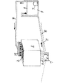
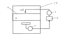
本発明は、ボイラー等の排ガスに使用する排煙脱硝装置において、シリカ・アルミナ・硫酸カルシウム系の被毒物質でコーティングされた活性の低下した触媒(バナジウムとチタニアを主成分とする脱硝触媒)2をバスケット1内に保持し、これを水槽3内の清水4内に浸漬して予め水洗いすること(図1)、又はシャワーノズル10での散水による触媒2の水洗い工程(図5)によって付着灰を取り除く構成、次にこれを常温の混液収容槽5内に浸漬し、混液6をポンプ7及びパイプ8で上記バスケット1内を通過循環させる混液での洗浄工程(図2)、又はシャワーノズル10によって混液6を散布する洗浄工程(図4)、洗浄後のバスケット1の付着混液を水又は希薄な有機酸(リンス液12)でリンスして洗い流すリンス工程13(図5)、及び図3、図6に示す送風ブロワー9による水切り乾燥工程からなる。
The present invention relates to a catalyst with reduced activity (denitration catalyst mainly composed of vanadium and titania) coated with a poisoning substance of silica, alumina and calcium sulfate in a flue gas denitration apparatus used for exhaust gas such as
<触媒層内での循環散布洗浄のケース>
基本的には、特許第3872656号及び特許第4263930号に記載の方法に準じて実施する。即ち、図7に示すように脱硝装置14内にセットされた状態の脱硝触媒2の上からシャワーノズル10によって混液を散布するが、その前の工程として図4のシャワーノズル10での散水による触媒の水洗い工程が追加される。
触媒の水洗いに先立ち、100本前後の触媒が収まったバスケット1間の隙間(バスケット1を複数台並設する場合)や、バスケット1内に並設されている隣接する触媒2間の隙間tに弾力性のあるスポンジ15をつめるか(図8)、或いは耐水テープ15で目張りを行う。
これは、バスケット1内や触媒2間の隙間t内に詰まっている灰は次の1、2の理由から、上記隙間tに、極力洗浄液がかからないようにすることが、薬品の使用量と濃度の低減から有利なためである。
<Case of circulating spray cleaning in the catalyst layer>
Basically, it is carried out according to the methods described in Japanese Patent Nos. 3,872,656 and 4,263,930. That is, as shown in FIG. 7, the mixed liquid is sprayed by the
Prior to washing the catalyst with water, there are gaps between the
This is because the amount of chemicals used and the concentration of ash clogged in the
1.完全に洗い流すには長時間を要し、且つ洗浄水量が大量に必要となり、
また排水処理量も増える。
2.除去すべき触媒表面の被毒物質の量に比べてはるかに多く、薬品消費量が多くなる。
1. It takes a long time to wash away completely, and a large amount of water is needed.
Also, the amount of wastewater treatment increases.
2. Compared to the amount of poisoning material on the catalyst surface to be removed, the chemical consumption is increased.
目張りを終えた触媒上部から清水を散水して触媒内の付着灰を洗い流し、触媒の下部から流れ出る水の濁りがない程度にまで十分に洗い流すことで、全ての触媒に十分吸水させる。
このとき発生した排水は、排水処理装置にかけて排水の性状に応じた処理を行い、放流する。
水洗い後の触媒バスケットから水が垂れない状態になったら、供給タンク5に溶解した2wt%のシュウ酸とフッ化水素酸0.5wt%又は0.5〜5.0wt%のフッ化アンモニウムとの混液6を所定流量と所定時間で触媒2上部から散布し、触媒2下部から流出してくる混液をシート上で回収し、ポンプ7で回収ピット5(又は回収タンク)に移送する(図4)。
回収ピット5に回収した混液は、供給タンクレベルの制御でポンプを自動発停させ、供給タンクへ補給を行う。
Clean water is sprinkled from the top of the catalyst after finishing the scuffing to wash away the adhering ash in the catalyst, and the water flowing out from the bottom of the catalyst is washed away to the extent that it does not become cloudy, so that all the catalysts absorb enough water.
The wastewater generated at this time is discharged through a wastewater treatment device according to the properties of the wastewater.
When water does not drip from the catalyst basket after washing with water, 2 wt% of oxalic acid dissolved in the
The mixed liquid recovered in the
混液6での洗浄条件は、洗浄流量が約15L/分・本、洗浄時間が5分程度で良い。
洗浄中は、混液濃度を定期的にモニターして濃度が初期濃度の約8割にまで低下したら、初期濃度になるように各酸液を回収タンクに追加補充する。
混液6で所定時間洗浄後、フッ化物を後工程に持ち込まないように付着混液を十分に水又は希薄(1〜2wt%)な有機酸(シュウ酸又はクエン酸)でリンスして洗い流した後、さらに触媒成分を含む水溶液でリンスする。そして、触媒バスケット1底部から送風ブロワー9で空気を送風し、液が滴り落ちない程度まで水切りを行う(図6)。上記触媒成分はバナジウム化合物(0.1〜2.0wt%)とタングステン化合物(0.1〜5.0wt%)であって、上記フッ化物洗浄による触媒成分の溶出を阻止し、触媒表面の触媒成分を補填することができる。
水切り後の触媒バスケット1は、触媒2を装着後、自然乾燥又は送風機による通風乾燥若しくは通常の運転操作の中で排ガスを導入し、乾燥することで触媒活性の改良効果が得られる。
The cleaning conditions with the mixed liquid 6 may be a cleaning flow rate of about 15 L / min · main and a cleaning time of about 5 minutes.
During washing, the concentration of the mixed solution is regularly monitored, and when the concentration drops to about 80% of the initial concentration, each acid solution is additionally replenished to the recovery tank so that the initial concentration is obtained.
After washing with the mixed solution 6 for a predetermined time, the adhering mixed solution is sufficiently rinsed with water or dilute (1 to 2 wt%) organic acid (oxalic acid or citric acid) so as not to bring the fluoride into the subsequent process, and then washed away. Furthermore, it rinses with the aqueous solution containing a catalyst component. Then, air is blown from the bottom of the
The
<脱硝装置から取り外しての洗浄のケース その1>
触媒バスケット1は、予め真空掃除機や圧縮空気によるエアブローで堆積灰や付着灰を取り除いた状態で、触媒バスケット1が完全に浸漬できるサイズの水槽3に清水4を張り込み、この水槽3に触媒バスケット1を1分間程度浸漬する(図1)。
浸漬後、触媒バスケット1を引き上げて、高さ20cm程度のH型鋼を平行に2本並べた上に触媒バスケット1を置き、水4が滴り落ちない程度まで水切りを行う。
<Case of cleaning after removing from the
In the
After soaking, the
水切り完了後、触媒バスケット1を2wt%のシュウ酸と0.5wt%のフッ化水素酸又は2.5%のフッ化アンモニウムとの混液6を完全に浸漬できる程度まで張り込んだ回収ピット5に約5分間浸漬する(図2)。この場合、回収ピット5内に水中ポンプ7を入れて、起動停止を行い、間欠的に混液6を攪拌させ溶解平衡状態を乱すことで洗浄除去効果を高めても良い。
所定時間浸漬した後、触媒バスケット1を引き上げて、フッ化物を後工程に持ち込まないように付着混液を十分に水又は希薄(1〜2wt%)な有機酸(シュウ酸又はクエン酸)でリンスし、さらに触媒成分(バナジウム化合物とタングステン化合物)を含む水溶液でリンスして洗い流した後、高さ20cm程度のH型鋼を平行に2本並べた上に触媒バスケット1を置き、底部からブロワー9で送風して、水が滴り落ちない程度まで水切りを行う(図3)。
水切り後の触媒バスケット1は、触媒2を装着後、通常の運転操作の中で排ガスを導入し、乾燥することで触媒2の活性の改良効果が得られる。
After draining is completed, the
After soaking for a predetermined time, the
After the draining of the
<脱硝装置から取り外しての洗浄のケース その2>
触媒バスケット1は、予め真空掃除機や圧縮空気によるエアブローで堆積灰や付着灰を取り除いた状態で、触媒バスケット1が完全に浸漬できるサイズの水槽3に清水4を張り込み、この水槽3に触媒バスケット1を1分間程度浸漬する(図1)。
浸漬後、触媒バスケット1を引き上げて、高さ20cm程度のH型鋼を平行に2本並べた上に触媒バスケット1を置き、水4が滴り落ちない程度まで水切りを行う(図3)。
<Case of cleaning after removing from the
In the
After the immersion, the
水洗い後の触媒バスケット1から水が垂れない状態になったら、供給タンク5に溶解した2wt%のシュウ酸とフッ化水素酸0.5wt%又は0.5〜5.0wt%のフッ化アンモニウムとの混液6を所定流量と所定時間で触媒上部から散布し、触媒下部から流出してくる混液をシート上で回収し、ポンプ7で回収ピット5(又は回収タンク)に移送する(図4)。
回収ピットに回収した混液は、供給タンクレベルの制御でポンプを自動発停させ、供給タンクへ補給を行う。
When water does not drip from the
The mixed liquid collected in the collection pit is supplied to the supply tank by automatically starting and stopping the pump by controlling the supply tank level.
混液6での洗浄条件は、洗浄流量が約15L/分・本、洗浄時間が5分程度で良い。
洗浄中は、混液濃度を定期的にモニターして濃度が初期濃度の約8割にまで低下したら、初期濃度になるように各酸液を回収ピット5に追加補充する。
混液6で所定時間洗浄後、フッ化物を後工程に持ち込まないように付着混液を十分に水又は希薄(1〜2wt%)な有機酸(シュウ酸又はクエン酸)でリンスし、さらに触媒成分(バナジウム化合物とタングステン化合物)を含む水溶液でリンスして洗い流した後(図5)、触媒バスケット1底部から送風ブロワー9で空気を送風し、液が滴り落ちない程度まで水切りを行う(図6)。
水切り後の触媒バスケット1は、触媒2を装着後、自然乾燥又は送風機による通風乾燥若しくは通常の運転操作の中で排ガスを導入し、乾燥することで触媒活性の改良効果が得られる。
The cleaning conditions with the mixed liquid 6 may be a cleaning flow rate of about 15 L / min · main and a cleaning time of about 5 minutes.
During the cleaning, the mixed solution concentration is regularly monitored, and when the concentration drops to about 80% of the initial concentration, each acid solution is additionally replenished to the
After washing with the mixed solution 6 for a predetermined time, the adhering mixed solution is sufficiently rinsed with water or dilute (1 to 2 wt%) organic acid (oxalic acid or citric acid) so as not to bring the fluoride into the subsequent process, and further the catalyst component ( After rinsing with an aqueous solution containing a vanadium compound and a tungsten compound (FIG. 5), air is blown from the bottom of the
The

サンプル触媒の性能測定結果に示されるように、水洗い工程を追加すると共に、希釈な有機酸(シュウ酸2wt%)とフッ化物の混液を用いることで、0.5wt%の低濃度のフッ化水素酸を使用した常温の混液(ケース3、11、14)、即ち低濃度のフッ化水素酸であっても触媒の十分な再生を実現することができることがわかった。また、0.5wt%、2.5wt%の低濃度のフッ化アンモニウム(又はフッ化ナトリウム)を使用した常温の混液(ケース7,8,8”)、即ち低濃度のフッ化アンモニウム等の水溶性フッ化物塩を使用しても触媒の十分な再生を実現することができることがわかった。
フッ化アンモニウム等の水溶性フッ化物塩の濃度は5.0wt%(ケース8’)が上限であり、これ以上フッ化アンモニウムの濃度を増しても触媒の再生能力は変わらないことがわかった。このことから、水溶性フッ化物塩の濃度は、0.5wt%〜5.0wt%の範囲内の何れかの濃度が好ましい。
また、有機酸はクエン酸(2wt%)を用いても、上記と同様の結果が得られた。
As shown in the performance measurement results of the sample catalyst, a water washing step is added and a dilute organic acid (
The concentration of water-soluble fluoride salt such as ammonium fluoride is 5.0 wt% (
Moreover, the same result as above was obtained even when citric acid (2 wt%) was used as the organic acid.
1 バスケット
2 触媒
3 水槽
4 清水
5 回収ピット
6 混液
7 ポンプ
8 パイプ
9 送風ブロワー
12 リンス液
13 リンス工程
DESCRIPTION OF
Claims (7)
Priority Applications (1)
| Application Number | Priority Date | Filing Date | Title |
|---|---|---|---|
| JP2010038145A JP4870217B2 (en) | 2009-07-10 | 2010-02-24 | Denitration catalytic activity improvement method in flue gas denitration equipment |
Applications Claiming Priority (3)
| Application Number | Priority Date | Filing Date | Title |
|---|---|---|---|
| JP2009163321 | 2009-07-10 | ||
| JP2009163321 | 2009-07-10 | ||
| JP2010038145A JP4870217B2 (en) | 2009-07-10 | 2010-02-24 | Denitration catalytic activity improvement method in flue gas denitration equipment |
Publications (2)
| Publication Number | Publication Date |
|---|---|
| JP2011031237A true JP2011031237A (en) | 2011-02-17 |
| JP4870217B2 JP4870217B2 (en) | 2012-02-08 |
Family
ID=43760837
Family Applications (1)
| Application Number | Title | Priority Date | Filing Date |
|---|---|---|---|
| JP2010038145A Active JP4870217B2 (en) | 2009-07-10 | 2010-02-24 | Denitration catalytic activity improvement method in flue gas denitration equipment |
Country Status (1)
| Country | Link |
|---|---|
| JP (1) | JP4870217B2 (en) |
Cited By (11)
| Publication number | Priority date | Publication date | Assignee | Title |
|---|---|---|---|---|
| JP2014507273A (en) * | 2011-02-03 | 2014-03-27 | シュテアグ エナジー サーヴィシィズ ゲゼルシャフト ミット ベシュレンクテル ハフツング | Method for treating an SCR catalyst with accumulated iron compounds |
| JP2016159272A (en) * | 2015-03-04 | 2016-09-05 | 中国電力株式会社 | Regeneration process of denitration catalyst |
| WO2017010402A1 (en) * | 2015-07-10 | 2017-01-19 | 三菱日立パワーシステムズ株式会社 | Denitration catalyst regeneration method, denitration catalyst regeneration system, and cleaning agent for denitration catalyst |
| CN106423194A (en) * | 2016-09-28 | 2017-02-22 | 北京科技大学 | Preparation method of low-temperature efficient sulfur-resistant and water-resistant denitration catalyst |
| CN106492821A (en) * | 2016-09-28 | 2017-03-15 | 北京科技大学 | A kind of efficient cryogenic sulfur resistive water resistant cooperates with the preparation method of denitration demercuration catalyst |
| KR20190082259A (en) | 2016-12-15 | 2019-07-09 | 미츠비시 히타치 파워 시스템즈 가부시키가이샤 | Method for regenerating used denitration catalyst |
| WO2020194851A1 (en) * | 2019-03-28 | 2020-10-01 | 三菱日立パワーシステムズ株式会社 | Denitration catalyst regeneration method and denitration catalyst regeneration system |
| WO2021100609A1 (en) * | 2019-11-20 | 2021-05-27 | 三菱パワー株式会社 | Catalyst cleaning method, catalyst cleaning device, and program |
| WO2021261477A1 (en) * | 2020-06-24 | 2021-12-30 | 三菱パワー株式会社 | Method for regenerating catslyst, apparatus for regenerating catslyst and program |
| CN115178302A (en) * | 2022-08-29 | 2022-10-14 | 潍柴动力股份有限公司 | Chemical polishing method of catalyst |
| CN120790245A (en) * | 2025-08-14 | 2025-10-17 | 美斯顿(天津)催化剂有限公司 | Regeneration liquid and regeneration method of corrugated plate denitration catalyst |
Citations (6)
| Publication number | Priority date | Publication date | Assignee | Title |
|---|---|---|---|---|
| JPS5998739A (en) * | 1982-11-30 | 1984-06-07 | Mitsubishi Heavy Ind Ltd | Regeneration of catalyst |
| JPS631429A (en) * | 1986-06-20 | 1988-01-06 | Ishikawajima Harima Heavy Ind Co Ltd | Denitrification catalyst regeneration method |
| JPH10156192A (en) * | 1996-12-03 | 1998-06-16 | Ishikawajima Harima Heavy Ind Co Ltd | Method and apparatus for regenerating denitration catalyst activity |
| JP3377715B2 (en) * | 1997-02-27 | 2003-02-17 | 三菱重工業株式会社 | Regeneration method of denitration catalyst |
| JP3872656B2 (en) * | 2001-03-16 | 2007-01-24 | 九州電力株式会社 | Method and apparatus for improving activity of denitration catalyst |
| JP4263930B2 (en) * | 2003-03-10 | 2009-05-13 | 九州電力株式会社 | Device for improving the activity of degraded honeycomb catalysts |
-
2010
- 2010-02-24 JP JP2010038145A patent/JP4870217B2/en active Active
Patent Citations (6)
| Publication number | Priority date | Publication date | Assignee | Title |
|---|---|---|---|---|
| JPS5998739A (en) * | 1982-11-30 | 1984-06-07 | Mitsubishi Heavy Ind Ltd | Regeneration of catalyst |
| JPS631429A (en) * | 1986-06-20 | 1988-01-06 | Ishikawajima Harima Heavy Ind Co Ltd | Denitrification catalyst regeneration method |
| JPH10156192A (en) * | 1996-12-03 | 1998-06-16 | Ishikawajima Harima Heavy Ind Co Ltd | Method and apparatus for regenerating denitration catalyst activity |
| JP3377715B2 (en) * | 1997-02-27 | 2003-02-17 | 三菱重工業株式会社 | Regeneration method of denitration catalyst |
| JP3872656B2 (en) * | 2001-03-16 | 2007-01-24 | 九州電力株式会社 | Method and apparatus for improving activity of denitration catalyst |
| JP4263930B2 (en) * | 2003-03-10 | 2009-05-13 | 九州電力株式会社 | Device for improving the activity of degraded honeycomb catalysts |
Cited By (25)
| Publication number | Priority date | Publication date | Assignee | Title |
|---|---|---|---|---|
| JP2014507273A (en) * | 2011-02-03 | 2014-03-27 | シュテアグ エナジー サーヴィシィズ ゲゼルシャフト ミット ベシュレンクテル ハフツング | Method for treating an SCR catalyst with accumulated iron compounds |
| JP2016159272A (en) * | 2015-03-04 | 2016-09-05 | 中国電力株式会社 | Regeneration process of denitration catalyst |
| KR102112426B1 (en) * | 2015-07-10 | 2020-05-19 | 미츠비시 히타치 파워 시스템즈 가부시키가이샤 | Denitrification catalyst regeneration method and denitration catalyst regeneration system, and denitration catalyst cleaning agent |
| WO2017010402A1 (en) * | 2015-07-10 | 2017-01-19 | 三菱日立パワーシステムズ株式会社 | Denitration catalyst regeneration method, denitration catalyst regeneration system, and cleaning agent for denitration catalyst |
| US11045799B2 (en) | 2015-07-10 | 2021-06-29 | Mitsubishi Power, Ltd. | Denitration catalyst regeneration method, denitration catalyst regeneration system, and cleaning agent for denitration catalyst |
| JPWO2017010402A1 (en) * | 2015-07-10 | 2017-08-31 | 三菱日立パワーシステムズ株式会社 | Denitration catalyst regeneration method, denitration catalyst regeneration system, and denitration catalyst cleaning agent |
| KR20180017103A (en) * | 2015-07-10 | 2018-02-20 | 미츠비시 히타치 파워 시스템즈 가부시키가이샤 | A regeneration method of a denitration catalyst, a regeneration system of a denitration catalyst, and a detergent |
| TWI640360B (en) * | 2015-07-10 | 2018-11-11 | 日商三菱日立電力系統股份有限公司 | Denitration catalyst regeneration method and denitration catalyst regeneration system and denitration catalyst detergent |
| CN106492821A (en) * | 2016-09-28 | 2017-03-15 | 北京科技大学 | A kind of efficient cryogenic sulfur resistive water resistant cooperates with the preparation method of denitration demercuration catalyst |
| CN106423194A (en) * | 2016-09-28 | 2017-02-22 | 北京科技大学 | Preparation method of low-temperature efficient sulfur-resistant and water-resistant denitration catalyst |
| KR20190082259A (en) | 2016-12-15 | 2019-07-09 | 미츠비시 히타치 파워 시스템즈 가부시키가이샤 | Method for regenerating used denitration catalyst |
| WO2020194851A1 (en) * | 2019-03-28 | 2020-10-01 | 三菱日立パワーシステムズ株式会社 | Denitration catalyst regeneration method and denitration catalyst regeneration system |
| JP2020163242A (en) * | 2019-03-28 | 2020-10-08 | 三菱日立パワーシステムズ株式会社 | Denitration catalyst regeneration method and denitration catalyst regeneration system |
| KR20230079497A (en) | 2019-03-28 | 2023-06-07 | 미츠비시 파워 가부시키가이샤 | Denitration catalyst regeneration method and denitration catalyst regeneration system |
| US12128393B2 (en) | 2019-03-28 | 2024-10-29 | Mitsubishi Heavy Industries, Ltd. | Denitration catalyst regeneration method and denitration catalyst regeneration system |
| KR20210124477A (en) | 2019-03-28 | 2021-10-14 | 미츠비시 파워 가부시키가이샤 | Regeneration method of denitration catalyst and regeneration system of denitration catalyst |
| CN113573812A (en) * | 2019-03-28 | 2021-10-29 | 三菱动力株式会社 | Regeneration method of denitration catalyst and regeneration system of denitration catalyst |
| KR102596835B1 (en) * | 2019-03-28 | 2023-11-02 | 미츠비시 파워 가부시키가이샤 | Denitrification catalyst regeneration method and denitrification catalyst regeneration system |
| WO2021100609A1 (en) * | 2019-11-20 | 2021-05-27 | 三菱パワー株式会社 | Catalyst cleaning method, catalyst cleaning device, and program |
| CN114761128A (en) * | 2019-11-20 | 2022-07-15 | 三菱重工业株式会社 | Catalyst cleaning method, catalyst cleaning device, and program |
| JP2021079341A (en) * | 2019-11-20 | 2021-05-27 | 三菱パワー株式会社 | Catalyst cleaning method, catalyst cleaning apparatus and program |
| WO2021261477A1 (en) * | 2020-06-24 | 2021-12-30 | 三菱パワー株式会社 | Method for regenerating catslyst, apparatus for regenerating catslyst and program |
| CN115178302A (en) * | 2022-08-29 | 2022-10-14 | 潍柴动力股份有限公司 | Chemical polishing method of catalyst |
| CN115178302B (en) * | 2022-08-29 | 2023-12-15 | 潍柴动力股份有限公司 | Chemical polishing method of catalyst |
| CN120790245A (en) * | 2025-08-14 | 2025-10-17 | 美斯顿(天津)催化剂有限公司 | Regeneration liquid and regeneration method of corrugated plate denitration catalyst |
Also Published As
| Publication number | Publication date |
|---|---|
| JP4870217B2 (en) | 2012-02-08 |
Similar Documents
| Publication | Publication Date | Title |
|---|---|---|
| JP4870217B2 (en) | Denitration catalytic activity improvement method in flue gas denitration equipment | |
| KR100626925B1 (en) | Regeneration method of used deNOx or dedioxin catalysts | |
| JP6298579B2 (en) | Denitration catalyst regeneration method, denitration catalyst regeneration system, and denitration catalyst cleaning agent | |
| US7723251B2 (en) | Method of regeneration of SCR catalyst | |
| JP7013258B2 (en) | Denitration catalyst regeneration method and denitration catalyst regeneration system | |
| CN103350004A (en) | SCR denitrification catalyst regeneration method and mixture for SCR denitrification catalyst regeneration liquid | |
| JP4578048B2 (en) | Denitration catalyst regeneration method | |
| CN108687029A (en) | A kind of cleaning of silicon material | |
| CN106732824A (en) | The regeneration washing liquid and the renovation process of denitrating catalyst of a kind of denitrating catalyst | |
| KR102596835B1 (en) | Denitrification catalyst regeneration method and denitrification catalyst regeneration system | |
| CN108187763A (en) | A kind of regeneration technology of denitration SCR catalyst | |
| JPH10156192A (en) | Method and apparatus for regenerating denitration catalyst activity | |
| CN102296008A (en) | Neutral cleaning agent for cleaning scaling substances on GGH (gas-gas heater) of flue gas desulphurization system | |
| WO2019004123A1 (en) | Regeneration method for denitration catalyst and regeneration system for denitration catalyst | |
| KR101153569B1 (en) | A method for regenerating scr catalyst | |
| TWI771685B (en) | Desulfurization, nitrification catalyst and catalyst device, and preparation, activation and regeneration method thereof | |
| JP3108937B2 (en) | Work cleaning method and cleaning device | |
| JP3872656B2 (en) | Method and apparatus for improving activity of denitration catalyst | |
| CN112473752A (en) | High-dust-blockage honeycomb type SCR denitration catalyst cleaning solution and preparation and cleaning methods thereof | |
| JP3873344B2 (en) | Denitration catalyst activity regeneration method and apparatus | |
| CN105032504B (en) | A kind of application of cleaning agent, cleaning method and cleaning agent for the dust stratification that cleans in SCR denitration | |
| JP2007160268A (en) | Denitration catalyst regeneration treatment method | |
| KR101143857B1 (en) | Acid pickling apparatus to prevent noxious gas leakage | |
| JP7679180B2 (en) | Method for regenerating catalyst, device for regenerating catalyst, and program | |
| JP2006105086A (en) | Method for regenerating diesel particulate filter |
Legal Events
| Date | Code | Title | Description |
|---|---|---|---|
| A977 | Report on retrieval |
Free format text: JAPANESE INTERMEDIATE CODE: A971007 Effective date: 20110810 |
|
| A131 | Notification of reasons for refusal |
Free format text: JAPANESE INTERMEDIATE CODE: A131 Effective date: 20110816 |
|
| A521 | Request for written amendment filed |
Free format text: JAPANESE INTERMEDIATE CODE: A523 Effective date: 20110922 |
|
| TRDD | Decision of grant or rejection written | ||
| A01 | Written decision to grant a patent or to grant a registration (utility model) |
Free format text: JAPANESE INTERMEDIATE CODE: A01 Effective date: 20111018 |
|
| A01 | Written decision to grant a patent or to grant a registration (utility model) |
Free format text: JAPANESE INTERMEDIATE CODE: A01 |
|
| A61 | First payment of annual fees (during grant procedure) |
Free format text: JAPANESE INTERMEDIATE CODE: A61 Effective date: 20111116 |
|
| R150 | Certificate of patent or registration of utility model |
Free format text: JAPANESE INTERMEDIATE CODE: R150 Ref document number: 4870217 Country of ref document: JP Free format text: JAPANESE INTERMEDIATE CODE: R150 |
|
| FPAY | Renewal fee payment (event date is renewal date of database) |
Free format text: PAYMENT UNTIL: 20141125 Year of fee payment: 3 |
|
| R250 | Receipt of annual fees |
Free format text: JAPANESE INTERMEDIATE CODE: R250 |
|
| R250 | Receipt of annual fees |
Free format text: JAPANESE INTERMEDIATE CODE: R250 |
|
| R250 | Receipt of annual fees |
Free format text: JAPANESE INTERMEDIATE CODE: R250 |
|
| R250 | Receipt of annual fees |
Free format text: JAPANESE INTERMEDIATE CODE: R250 |
|
| R250 | Receipt of annual fees |
Free format text: JAPANESE INTERMEDIATE CODE: R250 |
|
| R250 | Receipt of annual fees |
Free format text: JAPANESE INTERMEDIATE CODE: R250 |
|
| R250 | Receipt of annual fees |
Free format text: JAPANESE INTERMEDIATE CODE: R250 |
|
| R250 | Receipt of annual fees |
Free format text: JAPANESE INTERMEDIATE CODE: R250 |
|
| R250 | Receipt of annual fees |
Free format text: JAPANESE INTERMEDIATE CODE: R250 |
|
| R250 | Receipt of annual fees |
Free format text: JAPANESE INTERMEDIATE CODE: R250 |
|
| R250 | Receipt of annual fees |
Free format text: JAPANESE INTERMEDIATE CODE: R250 |
|
| R250 | Receipt of annual fees |
Free format text: JAPANESE INTERMEDIATE CODE: R250 |