JP2011027302A - Wind direction adjusting device and indoor unit for air conditioner - Google Patents
Wind direction adjusting device and indoor unit for air conditioner Download PDFInfo
- Publication number
- JP2011027302A JP2011027302A JP2009172016A JP2009172016A JP2011027302A JP 2011027302 A JP2011027302 A JP 2011027302A JP 2009172016 A JP2009172016 A JP 2009172016A JP 2009172016 A JP2009172016 A JP 2009172016A JP 2011027302 A JP2011027302 A JP 2011027302A
- Authority
- JP
- Japan
- Prior art keywords
- wind direction
- moving
- rotation center
- shaft
- bearing
- Prior art date
- Legal status (The legal status is an assumption and is not a legal conclusion. Google has not performed a legal analysis and makes no representation as to the accuracy of the status listed.)
- Granted
Links
- 238000007664 blowing Methods 0.000 claims description 11
- 230000008878 coupling Effects 0.000 claims description 7
- 238000010168 coupling process Methods 0.000 claims description 7
- 238000005859 coupling reaction Methods 0.000 claims description 7
- 238000009423 ventilation Methods 0.000 abstract description 9
- 230000000694 effects Effects 0.000 abstract description 7
- 238000006073 displacement reaction Methods 0.000 abstract 2
- 238000011144 upstream manufacturing Methods 0.000 description 5
- 238000004140 cleaning Methods 0.000 description 4
- 239000000463 material Substances 0.000 description 4
- 239000000428 dust Substances 0.000 description 3
- 239000011347 resin Substances 0.000 description 3
- 229920005989 resin Polymers 0.000 description 3
- 229920000122 acrylonitrile butadiene styrene Polymers 0.000 description 1
- 210000000078 claw Anatomy 0.000 description 1
- 239000000470 constituent Substances 0.000 description 1
- 230000003670 easy-to-clean Effects 0.000 description 1
- 238000009434 installation Methods 0.000 description 1
- 239000000314 lubricant Substances 0.000 description 1
- 230000001050 lubricating effect Effects 0.000 description 1
- 238000004519 manufacturing process Methods 0.000 description 1
- 230000005855 radiation Effects 0.000 description 1
- 239000003507 refrigerant Substances 0.000 description 1
- 238000005096 rolling process Methods 0.000 description 1
Images


Classifications
-
- F—MECHANICAL ENGINEERING; LIGHTING; HEATING; WEAPONS; BLASTING
- F24—HEATING; RANGES; VENTILATING
- F24F—AIR-CONDITIONING; AIR-HUMIDIFICATION; VENTILATION; USE OF AIR CURRENTS FOR SCREENING
- F24F1/00—Room units for air-conditioning, e.g. separate or self-contained units or units receiving primary air from a central station
- F24F1/0007—Indoor units, e.g. fan coil units
- F24F1/0011—Indoor units, e.g. fan coil units characterised by air outlets
-
- F—MECHANICAL ENGINEERING; LIGHTING; HEATING; WEAPONS; BLASTING
- F24—HEATING; RANGES; VENTILATING
- F24F—AIR-CONDITIONING; AIR-HUMIDIFICATION; VENTILATION; USE OF AIR CURRENTS FOR SCREENING
- F24F13/00—Details common to, or for air-conditioning, air-humidification, ventilation or use of air currents for screening
- F24F13/08—Air-flow control members, e.g. louvres, grilles, flaps or guide plates
- F24F13/10—Air-flow control members, e.g. louvres, grilles, flaps or guide plates movable, e.g. dampers
- F24F13/14—Air-flow control members, e.g. louvres, grilles, flaps or guide plates movable, e.g. dampers built up of tilting members, e.g. louvre
- F24F13/1426—Air-flow control members, e.g. louvres, grilles, flaps or guide plates movable, e.g. dampers built up of tilting members, e.g. louvre characterised by actuating means
-
- F—MECHANICAL ENGINEERING; LIGHTING; HEATING; WEAPONS; BLASTING
- F24—HEATING; RANGES; VENTILATING
- F24F—AIR-CONDITIONING; AIR-HUMIDIFICATION; VENTILATION; USE OF AIR CURRENTS FOR SCREENING
- F24F13/00—Details common to, or for air-conditioning, air-humidification, ventilation or use of air currents for screening
- F24F13/08—Air-flow control members, e.g. louvres, grilles, flaps or guide plates
- F24F13/10—Air-flow control members, e.g. louvres, grilles, flaps or guide plates movable, e.g. dampers
- F24F13/14—Air-flow control members, e.g. louvres, grilles, flaps or guide plates movable, e.g. dampers built up of tilting members, e.g. louvre
- F24F13/15—Air-flow control members, e.g. louvres, grilles, flaps or guide plates movable, e.g. dampers built up of tilting members, e.g. louvre with parallel simultaneously tiltable lamellae
-
- F—MECHANICAL ENGINEERING; LIGHTING; HEATING; WEAPONS; BLASTING
- F24—HEATING; RANGES; VENTILATING
- F24F—AIR-CONDITIONING; AIR-HUMIDIFICATION; VENTILATION; USE OF AIR CURRENTS FOR SCREENING
- F24F13/00—Details common to, or for air-conditioning, air-humidification, ventilation or use of air currents for screening
- F24F13/08—Air-flow control members, e.g. louvres, grilles, flaps or guide plates
- F24F13/10—Air-flow control members, e.g. louvres, grilles, flaps or guide plates movable, e.g. dampers
- F24F13/14—Air-flow control members, e.g. louvres, grilles, flaps or guide plates movable, e.g. dampers built up of tilting members, e.g. louvre
- F24F13/1426—Air-flow control members, e.g. louvres, grilles, flaps or guide plates movable, e.g. dampers built up of tilting members, e.g. louvre characterised by actuating means
- F24F2013/1473—Air-flow control members, e.g. louvres, grilles, flaps or guide plates movable, e.g. dampers built up of tilting members, e.g. louvre characterised by actuating means with cams or levers
Abstract
Description
本発明は風向調整装置および空気調和機の室内機、特に、空気調和機の室内機に設置される風向調整装置、および該風向調整装置が設置された空気調和機の室内機に関するものである。 The present invention relates to a wind direction adjusting device and an indoor unit of an air conditioner, and more particularly to a wind direction adjusting device installed in an indoor unit of an air conditioner, and an indoor unit of an air conditioner in which the wind direction adjusting device is installed.
空気調和機の室内機(室内ユニットに同じ)の吹出口には、冷却または加熱された空気の吹き出し方向を調整する風向調整装置が設置されている。かかる風向調整装置は、古くは、湾曲自在な軟質部を有する風向板(垂直フラップに同じ)を備え、軟質部を湾曲させることによって吹き出し方向を調整するものが開示されている(例えば、特許文献1参照)。
また、互いに平行に配置された駆動アームおよび従動アームと、駆動アームおよび従動アームに両端部が回動自在に接続された第一列の複数枚の風向板(ベーン)と、駆動アームおよび従動アームに両端部が回動自在に接続された第二列の複数枚の風向板(ベーン)と、を有し、駆動アーム、従動アームおよび第一列の複数枚の風向板によって形成される平行四辺形の傾斜角(底辺と斜辺とがなす角度)と、駆動アーム、従動アームおよび第二列の複数枚の風向板によって形成される平行四辺形の傾斜角とを相違させることによって、吹き出し方向を調整するものが開示されている(例えば、特許文献2参照)。
At the air outlet of the indoor unit (same as the indoor unit) of the air conditioner, a wind direction adjusting device that adjusts the blowing direction of the cooled or heated air is installed. In the past, such a wind direction adjusting device has been disclosed that includes a wind direction plate (same as a vertical flap) having a soft part that can be bent, and adjusts the blowing direction by curving the soft part (for example, Patent Documents). 1).
Further, a driving arm and a driven arm arranged in parallel to each other, a plurality of first-direction wind direction plates (vanes) whose both ends are rotatably connected to the driving arm and the driven arm, and the driving arm and the driven arm A plurality of wind direction plates (vanes) in a second row whose both ends are pivotally connected to each other, and formed by a drive arm, a driven arm, and a plurality of wind direction plates in the first row. By changing the inclination angle of the shape (the angle formed by the base and the hypotenuse) and the inclination angle of the parallelogram formed by the driving arm, the driven arm and the second row of wind direction plates, the blowing direction is changed. What is adjusted is disclosed (for example, refer to Patent Document 2).
特許文献1に開示された風向板は、両端に配置される剛質部に挟まれた軟質部は、湾曲自在および伸縮自在であるため、風向板を形成する材料が限定されると共に、剛質部と軟質部との接合面が剥離するおそれがあった。このため、製造コストが上昇すると共に、信頼性が低下するという問題があった。
一方、特許文献2に開示された第一列の風向板および第一列の風向板は、何れも一体的に成形されるため、前記問題は解消される。しかしながら、第一列の風向板と第二列の風向板とが、互いに千鳥状に配置、すなわち、吹き出し方向に垂直な面において、所定の間隔を空けて配置されている。このため、空気流が、第一列の風向板の風上側の端面と第二列の風向板の風上側の端面との両方に衝突し、通風抵抗が大きくなって、エネルギー損失が生じるという問題があった。
In the wind direction plate disclosed in Patent Document 1, since the soft portion sandwiched between the rigid portions disposed at both ends is bendable and extendable, the material for forming the wind direction plate is limited and rigid. There was a possibility that the joint surface between the part and the soft part might peel off. For this reason, there existed a problem that reliability increased while manufacturing cost raised.
On the other hand, the first row of wind direction plates and the first row of wind direction plates disclosed in Patent Document 2 are integrally formed, so the problem is solved. However, the first row of wind direction plates and the second row of wind direction plates are arranged in a staggered manner, that is, at a predetermined interval on a plane perpendicular to the blowing direction. For this reason, the problem is that the air flow collides with both the windward end surface of the first row wind direction plate and the windward end surface of the second row wind direction plate, resulting in increased ventilation resistance and energy loss. was there.
本発明は、上記のような課題を解決するためになされたものであって、通風抵抗の上昇を抑えて、省エネ効果が得られる風向調整装置、および該風向調整装置が設置された空気調和機の室内機を得るものである。 The present invention has been made in order to solve the above-described problems, and is provided with a wind direction adjusting device capable of suppressing an increase in ventilation resistance and obtaining an energy saving effect, and an air conditioner provided with the wind direction adjusting device. The indoor unit is obtained.
本発明に係る風向調整装置は、基台と、
該基台に基準回転中心において回転自在に設置された第1ベーンと、
該第1ベーンに連結回転中心において回転自在に設置された第2ベーンと、
前記第1ベーンが第1回転中心において、且つ、前記第2ベーンが第2回転中心において、それぞれ回転自在に設置された移動部材と、
該移動部材を前記基台に対して相対移動させる駆動手段と、
を有し、
前記移動部材が相対移動する量に応じて、前記基準回転中心と前記連結回転中心とを結ぶ第1仮想線と、前記連結回転中心と前記第2回転中心とを結ぶ第2仮想線と、がなす角度が変動することを特徴とする。
A wind direction adjusting device according to the present invention includes a base,
A first vane rotatably mounted on the base at a reference rotation center;
A second vane rotatably mounted on the first vane at the connecting rotation center;
A movable member rotatably installed at the first vane at the first rotation center and the second vane at the second rotation center;
Drive means for moving the moving member relative to the base;
Have
A first imaginary line connecting the reference rotation center and the connection rotation center and a second imaginary line connecting the connection rotation center and the second rotation center according to an amount of relative movement of the moving member. The formed angle varies.
本発明に係る風向調整装置は、第1ベーンが移動部材の移動によって基準回転中心を支点に、第1回転中心を力点にして回転され、連結回転中心が円弧状の軌跡を描いて移動する。同様に、第2ベーンは移動部材の移動によって連結回転中心を支点に、第2回転中心を力点にして回転される。
このとき、第1ベーンと第2ベーンとが共に連結回転中心において回転自在に連結されているため、第1ベーンと第2ベーンとは、あたかも一枚の板であるかのように挙動する。特に、正面方向に吹き出す際、第1ベーンと第2ベーンとが重なって1枚の平板状を呈するから、空気は第1ベーンまたは第2ベーンの一方の端面に衝突するだけであって、従来の千鳥配置の場合のように、第1ベーンおよび第2ベーンの双方の端面に衝突するようなことがない。したがって、空気流は滑らかとなって、通風抵抗の上昇が抑えられ、省エネ効果が得られる。
なお、前記では、第2ベーンは、連結回転中心を支点にして第2回転中心を力点にして回転されるとしているが、連結回転中心を力点にして第2回転中心を支点にして回転されるとみなしてもよい。
In the wind direction adjusting apparatus according to the present invention, the first vane is rotated with the reference rotation center as a fulcrum and the first rotation center as a power point by the movement of the moving member, and the connection rotation center moves along an arcuate locus. Similarly, the second vane is rotated by the movement of the moving member about the connection rotation center as a fulcrum and the second rotation center as a power point.
At this time, since both the first vane and the second vane are rotatably connected at the connection rotation center, the first vane and the second vane behave as if they are a single plate. In particular, when blowing out in the front direction, the first vane and the second vane overlap to form a single flat plate, so that the air only collides with one end face of the first vane or the second vane, As in the case of the staggered arrangement, the end faces of both the first vane and the second vane do not collide. Therefore, the air flow becomes smooth, an increase in ventilation resistance is suppressed, and an energy saving effect is obtained.
In the above description, the second vane is rotated with the connection rotation center as a fulcrum and the second rotation center as a power point. However, the second vane is rotated with the connection rotation center as a force point and the second rotation center as a fulcrum. May be considered.
[実施の形態1]
(空気調和機の室内機)
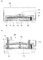
図1〜図3は本発明の実施の形態1に係る空気調和機の室内機を説明するものであって、図1の(a)は略正面から見た外観図、(b)は真下から真上に向かって見た外観図、図2は構成部材を分解して示す斜視図、図3は側面視の断面図である。なお、各図は模式的に描いたものであって、本発明は図示された形態に限定するものではない。
図1〜図3において、空気調和機の室内機(以下「室内機」と称す)100は、吸引口111および吹出口112を具備する本体110と、吸引口111から吹出口112に至る風路113を形成する送風手段120と、風路113内に配置された熱交換手段130と、風路113内に配置された左右風向調整装置(以下、「風向調整装置」と称す)200と、を有している。
[Embodiment 1]
(Air conditioner indoor unit)
1 to 3 illustrate an indoor unit of an air conditioner according to Embodiment 1 of the present invention, in which (a) in FIG. 1 is an external view as viewed from substantially the front, and (b) is from directly below. FIG. 2 is an exploded perspective view showing components and FIG. 3 is a sectional view in side view. In addition, each figure is drawn typically and this invention is not limited to the form shown in figure.
In FIG. 1 to FIG. 3, an indoor unit (hereinafter referred to as “indoor unit”) 100 of an air conditioner includes a
本体110は、室内の壁等に固定される基台114(以下、基台114側を「後面」と称す)と、基台114に固定される筐体115と、筐体115の前面に着脱自在かつ回動自在に設置される前面意匠パネル116と、を具備している。筐体115の上面には吸引口111が形成され、筐体115の下面(上面の一部を含む)には吹出口112が形成され、基台114の一部が風路113の一部(後面側)を形成している。
また、吹出口112には、前面上下風向ベーン301と底面上下風向ベーン302とを具備する上下風向調整装置300が設置されている。
The
In addition, the
熱交換手段130は後面側部分と前面側部分とを具備し、風路113の送風手段120よりも上流側に配置され、図示しない室外機から供給される冷媒が流通する伝熱管131と、伝熱管131が貫通する複数枚の放熱フィン132とを具備している。
そして、熱交換手段130の前面側部分の下方には、ドレンパンユニット140が設置されている。ドレンパンユニット140は熱交換手段130から滴下したドレンを受け止めるドレンパン上面141と、風路113の一部(前面ないし下面側)を形成するドレンパン下面142と、を具備している。
The heat exchanging means 130 includes a rear surface side portion and a front surface side portion, and is disposed upstream of the air blowing means 120 of the
A
そして、ドレンパン下面142に風向調整装置200が設置されている。風向調整装置200は実施の形態2において詳細に説明する風向調整装置200であるため、実施の形態1においては簡単に説明する。すなわち、風向調整装置200は、ドレンパン下面142に設置された基台40と、基台40に基準回転中心Aにおいて回転自在に設置された第1部材10と、第1部材10に回転自在に設置された第2部材20とを有している。
このとき、風路113に対してなす第1部材10の角度と、風路113に対してなす第2部材20の角度とが相違しているから、たとえば、上流側に配置された第2部材20の角度は小さく、下流側に配置された第1部材10の角度を大きくすることができ、空気流れを左右方向の所望の方向に滑らかに変更することができる。したがって、通風抵抗の上昇が抑えられ、省エネ効果が得られる(これについては、実施の形態2において詳細に説明する)
The wind
At this time, since the angle of the
なお、以下の説明の便宜上、基準回転中心Aの方向を「Z方向」、Z方向に垂直で本体110の幅方向を「X方向」、Z方向に垂直で本体110の略前後方向(正確には、前面かつ下面に向かった傾斜している方向)を「Y方向」と定義する(実施の形態2においても同様)。したがって、図1の(a)は正面側から「−Y方向」に見た外観図であり、図1の(b)は、図3の紙面の下方から上方に(本体110の真下から真上に)向かって見た外観図である。
For the convenience of the following description, the direction of the reference rotation center A is the “Z direction”, the width direction of the
さらに、基台114には、電気品箱117が装着されている。また、風路113の吸引口111の近くにはフィルター151が着脱自在かつ移動自在に設置されている。室内機100はフィルター自動清掃装置ユニット150を具備するため、前面寄りの位置に、フィルター151から落下した塵埃を貯溜するためのダストボックス152が設置されている。
また、室内機100には、運転状況等を前面意匠パネル116に表示する表示装置161と、室内に居る人間の位置(人間の不在を含む)を検知する赤外線センサー162と、が幅方向の略中央に設置されている。
なお、本発明は、フィルター自動清掃装置ユニット150、表示装置161、あるいは赤外線センサー162の設置を必須とするものではないから、これらの設置を省略してもよい。
Further, an
In addition, the
In the present invention, the automatic filter
[実施の形態2]
(風向調整装置)
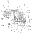
図4〜図7本発明の実施の形態2に係る風向調整装置を説明するものであって、図4は模式的に示す側面図、図5は構成部材を分解して示す斜視図、図6は組立状況を示す斜視図(正面吹き、および斜め吹き)、図7はリンク機構を説明する平面図(正面吹き、および斜め吹き)である。なお、各図は模式的に描いたものであって、本発明は図示された形態に限定するものではない。
図4〜図7において、風向調整装置200は、第1部材10と、第2部材20と、移動部材30と、基台40と、駆動手段50と、を組み立てたものである。基台40は、室内機100(実施の形態1)のドレンパン下面142に設置されるものである。
[Embodiment 2]
(Wind direction adjusting device)
4 to 7 illustrate a wind direction adjusting apparatus according to Embodiment 2 of the present invention, in which FIG. 4 is a schematic side view, FIG. 5 is an exploded perspective view of constituent members, and FIG. FIG. 7 is a perspective view (front blow and oblique blow) showing the assembly situation, and FIG. 7 is a plan view (front blow and oblique blow) explaining the link mechanism. In addition, each figure is drawn typically and this invention is not limited to the form shown in figure.
4 to 7, the wind
(第1部材)
第1部材10は、基準軸11と、基準軸11の中心線(以下、「基準回転中心A」と称す)を含む平面で、板状の第1風向板(第1ベーンに同じ)12と、を有している。第1風向板12には、一方の側縁13から基準回転中心Aに向かって陥入する切欠部14が形成されている。
また、切欠部14の下端縁14aで一方の側縁13の近くに上端縁14bに向かって突出して形成され、基準回転中心Aと平行な中心線(以下、「連結回転中心B」と称す)を具備する下連結軸15aと、切欠部14の上端縁14bで一方の側縁13の近くに下端縁14aに向かって突出して形成され、下連結軸と同一の中心線(連結回転中心B)を具備する上連結軸15bが設けられている。なお、下連結軸15aおよび上連結軸15bをまとめて「連結軸15」と称す場合がある。
(First member)
The
In addition, the
さらに、切欠部14の下端縁14aに上端縁14bに向かって突出して形成され、基準軸11と下連結軸15aとの間に配置された第1移動軸16が設けられている(以下、第1移動軸16の軸心を「第1回転中心C]と称す)。また、下連結軸15aおよび上連結軸15bには、それぞれ連結回転中心Bに垂直な上端面および下端面を具備する下連結座15cおよび上連結座15dが設けられ、第1移動軸16には第1回転中心Cに垂直な上端面を具備する第1移動座16cが設けられている。
なお、第1風向板12の板厚は全域で均一ではなく、切欠部14の周囲において厚く、特に、切欠部14の上端縁14bにおいては第1風向板12の面に垂直方向にフランジ状に突出したテーブル状を呈している。このとき、本発明は第1部材10の形態を図示するものに限定するものではなく、組み立てられて使用される際の、第1部材10の各部に作用する力や空気流との関係において決定される設計的事項である。また、第1部材10の数量は限定するものではない。
Further, a first moving
The thickness of the first
(第2部材)
第2部材20は、下連結軸15aおよび上連結軸15bを回転自在に支持する同一の中心線(組立状態において連結回転中心Bに一致する)を具備する下連結軸受25aおよび上連結軸受25bと、下連結軸受25aおよび上連結軸受25bの中心線を含む平面で、下連結軸受25aおよび上連結軸受25bの側面の一方側に突出して形成された第2風向板(第1ベーンに同じ)22とを有している。なお、下連結軸受25aおよび上連結軸受25bをまとめて「連結軸受25」と称す場合がある。
また、下連結軸受25aおよび上連結軸受25bの側面の他方側(第2風向板22とは反対の方向)に突出する突出部24が設けられ、突出部24の下面には第2移動軸26(以下、第2移動軸26の軸心を「第2回転中心D」と称す)が、突出部24の上面には当接突起27が、それぞれ設けられている。
(Second member)
The
In addition, a
そして、下連結軸受25aの上端面、上連結軸受25bの下端面、および突出部24の下面は、それぞれ両者の中心線(組立状態において連結回転中心Bに一致する)に垂直に形成されている。
したがって、組立状態において、第1部材10の下連結座15cの上端面および上連結座15dの下端面は、それぞれ第2部材20の下連結軸受25aの上端面および上連結軸受25bの下端面に当接する(なお、図4においては、各部の組立状態の理解を容易にするため、かかる当接する部材間に隙間を設けて描いている)。
And the upper end surface of the
Therefore, in the assembled state, the upper end surface of the
(移動部材)
移動部材30は、長手方向が組立状態においてX方向に一致する移動本体部33と、移動本体部33に対して垂直方向(組立状態においてY方向)に突出した移動腕部34と、を有している。そして、移動本体部33には第1移動軸受31が、移動腕部34には第2移動軸受32が、それぞれ形成されている。
第1移動軸受31は、組立状態において、第1部材10の第1移動軸16を回転自在に支持するものであって、移動本体部33の下面は、少なくとも第1移動座16cの上端面が当接する範囲が第1移動軸受31の軸心に垂直な平面に形成されている。したがって、組立状態において、第1部材10の第1移動座16cの上端面は移動本体部33の下面に当接する(なお、図4においては、各部の組立状態の理解を容易にするため、かかる当接する部材間に隙間を設けて描いている)。
また、第1移動軸受31の長手方向の両側には、貫通するスリット状の移動溝31aが形成され、第1移動軸受31への第1移動軸16の設置(陥入)を容易にしている。
(Moving member)
The moving
The first moving
Further, a slit-like moving groove 31 a is formed on both sides of the first moving
一方、第2移動軸受32は、組立状態において、第2部材20の第2移動軸26を回転自在およびY方向に移動自在に支持するものであって、Y方向に長い長孔である。また、組立状態において、移動腕部34の上面の少なくとも第2移動軸受32の周囲は第1移動軸受31の軸心に垂直な平面に形成されている。
このとき、組立状態において、移動腕部34の上面は、第2部材20の突出部24の下面が当接する(なお、図4においては、各部の組立状態の理解を容易にするため、かかる当接する部材間に隙間を設けて描いている)。
On the other hand, the second moving
At this time, in the assembled state, the upper surface of the
(駆動手段)
さらに、移動本体部33の一方の端部には、連結棒51の一方の端部が回転自在に接続され、連結棒51の他方の端部には、モーター連結部材52が回転自在に接続されている。
モーター連結部材52は、モーター53の出力軸に接続されるモーター接続部52aと、モーター接続部52aに固定され、先端が連結棒51に接続されるモーター連結アーム52bと、を有している。
したがって、モーター53が回転すると、モーター連結棒は並進運動をすることになる。なお、モーター連結部材52は前記構成に限定するものではなく、ラック/ピニオン構造でもよい。また、モーター53に替えて、ソレノイド等のアクチュエータを設置してもよい。
(Driving means)
Further, one end of the connecting
The
Therefore, when the
また、図4に示す組立状態において、第1移動軸16が第1移動軸受31を貫通して移動本体部33の上面から突出しているため、第1移動軸16と第2部材の突出部24との干渉を回避するため、かかる突出量よりも僅かに大きい量、移動腕部34の上面が移動本体部33の上面から突出している。このとき、移動本体部33と移動腕部34との厚さを同じにしたり(移動本体部33の下面と移動腕部34の下面との間に段差が生じる)、移動本体部33を第1移動軸16の全長を収納自在な厚さにしたり(移動本体部33の上面と移動腕部34の上面との間に段差が無くなり、重量が増加する)してもよい。
In the assembled state shown in FIG. 4, the first moving
(基台)
基台40は、組立状態において、基準軸11の端面を基準回転中心Aに対して垂直に支持する支持面41と、基準軸11が基台40から離脱しないように、且つ、基準軸11を基準回転中心Aを中心に回転自在に保持する保持手段(基準軸11の側面に突出して形成された円盤状の基準軸フランジ11aを包囲する爪)42とを有している。
また、基台40の一方の端部には、ドレンパン下面142に回転自在に係止する回転係止部43が、他方の端部には、ドレンパン下面142に設置された基台40が回転しないように固定するための固定係止部44が、設けられている。
すなわち、後記するように、室内機100の運転中は、基台40は風路113に対して垂直方向(X方向)に設置され、室内機100を清掃する際には、風路113に対して平行に設置され、一部は、吹出口112から本体110の外部に突き出すようにすることが可能になっている。
(Base)
In the assembled state, the
Moreover, the rotation latching | locking
That is, as will be described later, during the operation of the
(素材)
以上は、基台40はPP樹脂、第1部材10はABS樹脂、第2部材20はPOM樹脂、移動部材30はPP樹脂によって、それぞれ形成し、連結される樹脂同士を異種材料としている。本発明はこれらの部材を形成する素材を前記組み合わせに限定するものではなく、他の組み合わせでもよい。また、同一材料同士が連結される(当接する)ようにして、転結部(当接部)に潤滑手段を設置する(潤滑材の塗布する)等をしてもよい。
(Material)
As described above, the
(動作−正面吹き)
図6の(a)および(b)において、風向調整装置200は、第1部材10の基準軸11(基準回転中心A)、第1移動軸16(第1回転中心C)および連結軸15(連結回転中心B)がY方向で一直線上に位置している。また、第1部材20の、第2移動軸26(第2回転中心D)および連結軸受25(連結回転中心B)がY方向で一直線上に位置している。
したがって、第1風向板12と第2風向板22とは、Y方向で一直線上に並んでいる。このとき、第1風向板12の一方の側縁13と第2風向板22の他方の側縁23とは近接しているから、両者はあたかも一枚の平板のような形態を呈している。
したがって、空気は第2風向板22の風上側の端面に衝突するだけであって、従来の千鳥配置(所定の間隔を空けて平行に配置されている)の場合のように第1風向板12および第2風向板22の双方の端面に衝突するようなことがない。したがって、空気流は滑らかとなって、通風抵抗の上昇が抑えられ、省エネ効果が得られる。
(Operation-Front blow)
6A and 6B, the airflow
Therefore, the 1st
Therefore, air only collides with the windward end face of the second
すなわち、第2風向板22を風路113の上流側に、第1風向板12を風路113の下流側に配置すれば、空気流は両者の側縁に衝突したり、両者の側縁から剥離したりすることがないから、通風抵抗の上昇が抑えられ、省エネ効果が得られる。
このとき、第1風向板12および第2風向板22は何れも、一方の面(たとえば、+X方向側の面)が正圧面(流速が速い)に、他方の面(たとえば、−X方向側の面)が負圧面(流速が遅い)に、明りょうになるものではないため、流れのバラツキによって、第1風向板12または第2風向板22の一方または両方に振動が生じる場合がある。しかしながら、風向調整装置200は、正面吹きのとき、第2部材20の当接突起27が、第1部材10の切欠部14の上端縁14bに当接しているから、かかる振動が抑えられている。
That is, if the second
At this time, in both the first
(動作−斜め吹き)
図7の(a)および(b)において、風向調整装置200の第1部材10は、移動部材30(第1移動軸受31)が−X方向に移動させられているから、第1移動軸16(第1回転中心C)および連結軸15(連結回転中心B)は、固定点である基準軸11(基準回転中心A)に対してそれぞれ円弧状の軌跡を描いて、主に−X方向に移動している。そして、基準軸11(基準回転中心A)、第1移動軸16(第1回転中心C)および連結軸15(連結回転中心B)を結ぶ第1仮想線L1が、Y方向に対して「角度(以下、「第1傾斜角度」と称す)φ」傾斜している。
一方、第2部材20は、連結軸受25が連結軸15と同様に移動する。また、第2移動軸26(第2回転中心D)は第1移動軸16と同じ距離だけ−X方向に移動すると共に、第2移動軸受32内を−Y方向に移動している。したがって、連結軸受25(第2連結回転中心B)と第2移動軸26(第2回転中心D)とを結ぶ第2仮想線L2は、Y方向に対して「角度(以下、「第2傾斜角度」と称す)θ」傾斜している。
(Operation-oblique blow)
7 (a) and 7 (b), the
On the other hand, in the
そして、第1風向板12の一方の側縁13と第2風向板22の他方の側縁23とは近接しているから、両者はあたかも一枚の平板が連結軸15(連結軸受25)において、折れ曲がったような形態を呈している。
すなわち、正面吹き同様に、第2風向板22を風路113の上流側に、第1風向板12を風路113の下流側に配置すれば、空気流は両者の側縁に衝突したり、両者の側縁から剥離したりすることがないから、通風抵抗の上昇が抑えられ、省エネ効果が得られる。
このとき、第2部材20の当接突起27が、第1部材10の切欠部14の上端縁14bから離れているが、第1風向板12および第2風向板22は何れも、一方の面(たとえば、+X方向側の面)が正圧面(流速が速い)に、他方の面(たとえば、−X方向側の面)が負圧面(流速が遅い)に、明りょうになるため、空気流にバラツキが生じても、第1風向板12または第2風向板22の一方または両方に振動が生じることはない(少ない)。
And since one
That is, similarly to the front blowing, if the second
At this time, the
図7の(b)において、第1部材10の第1移動軸16と連結軸15との中心間距離を「m」、第2部材20の第2移動軸26と連結軸受25との中心間距離を「n」とすると、両者には
m・sin(φ)=n・sin(θ)・・・・・・式(1)
の関係がある。
したがって、たとえば、下流側の配置される第1風向板12の風路113に対する第1傾斜角度φを、上流側の配置される第2風向板12の風路113に対する第2傾斜角度θの「2倍」にするには、
m・sin(2・θ)=n・sin(θ)・・・・・・式(2)
n/m=2・cos(θ) ・・・・・・式(3)
の関係があればよい。
In FIG. 7B, the distance between the centers of the first moving
There is a relationship.
Therefore, for example, the first inclination angle φ with respect to the
m · sin (2 · θ) = n · sin (θ) ··· Equation (2)
n / m = 2 · cos (θ) (3)
If there is a relationship.
したがって、角度θを「−30°〜+30°(−3<θ<+30)」で変更する場合、たとえば、「cos(20°)=0.940」を代入して、
n/m=1.88 ・・・・・・式(4)
となる。
また、第2移動軸受26のY方向の長さ「p」は、
p=n・(cos(0°)−cos(30°)) ・・・・・・式(5)
p=n・(1−0.866)=0.13・n ・・・・・・式(6)
となる(なお、n/mを固定すると、φ/θの値が僅かに変動するから、式(6)は厳密には正確でない)。
Therefore, when the angle θ is changed from “−30 ° to + 30 ° (−3 <θ <+30)”, for example, “cos (20 °) = 0.940” is substituted,
n / m = 1.88 Expression (4)
It becomes.
Further, the length “p” of the second moving bearing 26 in the Y direction is:
p = n · (cos (0 °) −cos (30 °)) (5)
p = n · (1−0.866) = 0.13 · n Equation (6)
(Note that if n / m is fixed, the value of φ / θ slightly fluctuates, so that the expression (6) is not strictly accurate).
以上説明した、風向調整装置200において、たとえば、連結軸15の中心と連結軸受25と中心とが連結回転中心Bにおいて一致しているとか、連結回転中心Bに垂直な上端面および下端面を具備する下連結座15cおよび上連結座15dが設けられるとか、記載されているが、かかる「一致」や「垂直」は幾何学的に厳密な「一致」や「垂直」を指すものではなく、工業的に許容される誤差を含むものである。
また、軸と該軸を支持する軸受との設置場所については、設置位置を入れ替えてもよい。たとえば、第1部材に連結軸15を設けて第2部材に連結軸受25を設けているのに替えて、第2部材に連結軸を設けて第2部材に該連結軸を支持する連結軸受を設けてもよい。
さらに、第1移動軸16を切欠部14の上端縁14bに設置して、移動部材30を第2部材20の突出部24の上方に配置してもよい。このとき、第2移動軸26は突出部24の上面に設けられる。
In the wind
Further, the installation positions of the shaft and the bearing that supports the shaft may be switched. For example, instead of providing the connecting shaft 15 on the first member and the connecting bearing 25 on the second member, a connecting bearing that provides the connecting shaft on the second member and supports the connecting shaft on the second member is provided. It may be provided.
Further, the first moving
図1の(b)において、室内機100は停止し、風向調整装置200は吹出口112から外側に突き出している。すなわち、基台40の固定係止部44がドレンパン下面142から離され、回転係止部43を中心に回転している。したがって、左右に配置された一対の風向調整装置200は観音開き状に開いている。よって、本体110の内部の清掃や風向調整装置200自体の清掃が容易になる。
In FIG. 1B, the
本発明によれば、通風抵抗の上昇を抑えて、空気の吹き出し方向を設定(変更)することができるため、省エネ性に優れているから、空気吹出口に設置される各種風向調整装置として、また、該風向調整装置が設置される各種空気調和機の室内機として、広く利用することができる。 According to the present invention, since it is possible to set (change) the blowing direction of air while suppressing an increase in ventilation resistance, since it is excellent in energy saving, as various wind direction adjusting devices installed at the air outlet, Further, it can be widely used as an indoor unit of various air conditioners in which the wind direction adjusting device is installed.
10;第1部材、11;基準軸、11a;基準軸フランジ、12;第1風向板、13;側縁、14;切欠部、14a;下端縁、14b;上端縁、15a;下連結軸、15b;上連結軸、15c;下連結座、15d;上連結座、16;第1移動軸、16c;第1移動座、20;第2部材、22;第2風向板、23;側縁、24;突出部、25a;下連結軸受、25b;上連結軸受、26;第2移動軸、27;当接突起、30;移動部材、31;第1移動軸受、31a;移動溝、32;第2移動軸受、33;移動本体部、34;移動腕部、40;基台、41;支持面、43;回転係止部、44;固定係止部、50;駆動手段、51;連結棒、52;モーター連結部材、52a;モーター接続部、52b;モーター連結アーム、53;モーター、100;室内機、110;本体、111;吸引口、112;吹出口、113;風路、114;基台、115;筐体、116;前面意匠パネル、117;電気品箱、120;送風手段、130;熱交換手段、131;伝熱管、132;放熱フィン、140;ドレンパンユニット、141;ドレンパン上面、142;ドレンパン下面、150;フィルター自動清掃装置ユニット、151;フィルター、152;ダストボックス、161;表示装置、162;赤外線センサー、200;風向調整装置、300;上下風向調整装置、301;前面上下風向ベーン、302;底面上下風向ベーン、A;基準回転中心、B;連結回転中心、C;第1回転中心、D;第2回転中心、L1;第1仮想線、L2;第2仮想線、φ;第1傾斜角度、θ;第2傾斜角度。
10; first member, 11; reference shaft, 11a; reference shaft flange, 12; first wind direction plate, 13; side edge, 14; notch, 14a; lower edge, 14b; upper edge, 15a; 15b; upper connecting shaft, 15c; lower connecting seat, 15d; upper connecting seat, 16; first moving shaft, 16c; first moving seat, 20; second member, 22; second wind direction plate, 23; 24; projecting portion, 25a; lower connecting bearing, 25b; upper connecting bearing, 26; second moving shaft, 27; abutting protrusion, 30; moving member, 31; first moving bearing, 31a; 2 moving bearings, 33; moving body, 34; moving arm, 40; base, 41; support surface, 43; rotation locking portion, 44; fixed locking portion, 50; driving means, 51; 52; motor connecting member, 52a; motor connecting portion, 52b; motor connecting arm, 53; motor, 1 0; indoor unit, 110; main body, 111; suction port, 112; air outlet, 113; air channel, 114; base, 115; housing, 116; front design panel, 117; , 130; Heat exchange means, 131; Heat transfer tube, 132; Radiation fin, 140; Drain pan unit, 141; Drain pan upper surface, 142; Drain pan lower surface, 150; Filter automatic cleaning device unit, 151; Filter, 152; Dust box, 161; Display device 162; Infrared sensor 200; Wind direction adjusting device 300; Vertical air direction adjusting device 301; Front vertical wind direction vane 302; Bottom vertical wind direction vane A; Standard rotation center B; 1 rotation center, D; second rotation center, L1; first imaginary line, L2; second imaginary line, φ: first inclination angle, θ: second inclination angle.
Claims (5)
該基台に基準回転中心において回転自在に設置された第1ベーンと、
該第1ベーンに連結回転中心において回転自在に設置された第2ベーンと、
前記第1ベーンが第1回転中心において、且つ、前記第2ベーンが第2回転中心において、それぞれ回転自在に設置された移動部材と、
該移動部材を前記基台に対して相対移動させる駆動手段と、
を有し、
前記移動部材が相対移動する量に応じて、前記基準回転中心と前記連結回転中心とを結ぶ第1仮想線と、前記連結回転中心と前記第2回転中心とを結ぶ第2仮想線と、がなす角度が変動することを特徴とする風向調整装置。 The base,
A first vane rotatably mounted on the base at a reference rotation center;
A second vane rotatably mounted on the first vane at the connecting rotation center;
A movable member rotatably installed at the first vane at the first rotation center and the second vane at the second rotation center;
Drive means for moving the moving member relative to the base;
Have
A first imaginary line connecting the reference rotation center and the connection rotation center and a second imaginary line connecting the connection rotation center and the second rotation center according to an amount of relative movement of the moving member. A wind direction adjusting device characterized in that the angle formed changes.
前記基準軸を回転自在に支持する基台と、
前記一対の連結軸を回転自在に支持する一対の連結軸受と、該連結軸受の中心線を含む平面で、前記連結軸受の側面の一方側に突出して形成された第2風向板と、前記連結軸受の側面の他方側に突出して形成された突出部と、該突出部に形成された第2移動軸と、を有する第2部材と、
前記基台に対して相対移動自在で、前記第1移動軸を回転自在に支持する第1移動軸受と、前記第2移動軸を回転自在に支持する第2移動軸受と、を有する移動部材と、
前記移動部材を前記基台に対して相対移動させる駆動手段と、
を有し、
前記第1移動軸受と前記第2移動軸受とが、前記移動部材の前記基台に対する相対移動の方向に垂直方向で所定の距離だけ離れていることを特徴とする風向調整装置。 A first wind direction plate having a reference axis, a plane including a center line of the reference axis, and having a notch that is recessed from one side edge toward the center line; and the one side edge at the notch A pair of connecting shafts that project in the vicinity and have a center line that is parallel to the center line of the reference shaft, are formed to project from the notch, and are disposed between the reference shaft and the connecting shaft. A first member having a first movement axis;
A base that rotatably supports the reference shaft;
A pair of coupling bearings rotatably supporting the pair of coupling shafts; a second wind direction plate formed on a plane including a center line of the coupling bearing and projecting from one side surface of the coupling bearing; and the coupling A second member having a protrusion formed to protrude to the other side of the side surface of the bearing, and a second moving shaft formed on the protrusion;
A moving member having a first moving bearing that is movable relative to the base and that rotatably supports the first moving shaft; and a second moving bearing that rotatably supports the second moving shaft; ,
Drive means for moving the moving member relative to the base;
Have
The wind direction adjusting device according to claim 1, wherein the first moving bearing and the second moving bearing are separated by a predetermined distance in a direction perpendicular to a direction of relative movement of the moving member with respect to the base.
前記吸引口から前記吹出口に至る風路を形成する送風手段と、
前記風路内に配置された熱交換手段と、
前記風路内に配置された請求項1乃至4の何れかに記載の風向調整装置と、
を有することを特徴とする空気調和機の室内機。
A body having a suction port and a blowout port;
A blowing means for forming an air passage from the suction port to the blowout port;
Heat exchange means disposed in the air path;
The wind direction adjusting device according to any one of claims 1 to 4, which is disposed in the air path;
An indoor unit of an air conditioner characterized by comprising:
Priority Applications (3)
| Application Number | Priority Date | Filing Date | Title |
|---|---|---|---|
| JP2009172016A JP5042281B2 (en) | 2009-07-23 | 2009-07-23 | Wind direction adjusting device and air conditioner indoor unit |
| EP10003179.8A EP2292984B1 (en) | 2009-07-23 | 2010-03-25 | Wind direction adjusting apparatus and indoor unit of air conditioner |
| CN2010101716769A CN101963388B (en) | 2009-07-23 | 2010-04-28 | Wind direction adjusting apparatus and indoor unit of air conditioner |
Applications Claiming Priority (1)
| Application Number | Priority Date | Filing Date | Title |
|---|---|---|---|
| JP2009172016A JP5042281B2 (en) | 2009-07-23 | 2009-07-23 | Wind direction adjusting device and air conditioner indoor unit |
Publications (3)
| Publication Number | Publication Date |
|---|---|
| JP2011027302A true JP2011027302A (en) | 2011-02-10 |
| JP2011027302A5 JP2011027302A5 (en) | 2011-08-25 |
| JP5042281B2 JP5042281B2 (en) | 2012-10-03 |
Family
ID=42990239
Family Applications (1)
| Application Number | Title | Priority Date | Filing Date |
|---|---|---|---|
| JP2009172016A Expired - Fee Related JP5042281B2 (en) | 2009-07-23 | 2009-07-23 | Wind direction adjusting device and air conditioner indoor unit |
Country Status (3)
| Country | Link |
|---|---|
| EP (1) | EP2292984B1 (en) |
| JP (1) | JP5042281B2 (en) |
| CN (1) | CN101963388B (en) |
Cited By (6)
| Publication number | Priority date | Publication date | Assignee | Title |
|---|---|---|---|---|
| JP2013044511A (en) * | 2011-08-26 | 2013-03-04 | Daikin Industries Ltd | Air conditioner |
| KR200466184Y1 (en) * | 2011-01-03 | 2013-04-05 | 한전케이피에스 주식회사 | A nipple type type link-road structure |
| JP2014009826A (en) * | 2012-06-28 | 2014-01-20 | Sharp Corp | Air conditioner |
| CN107860067A (en) * | 2017-11-27 | 2018-03-30 | 广东美的制冷设备有限公司 | Cabinet air-conditioner and air conditioner |
| CN108151271A (en) * | 2018-01-29 | 2018-06-12 | 珠海格力电器股份有限公司 | Wind guiding mechanism, air conditioner indoor unit and air conditioner |
| WO2019008666A1 (en) * | 2017-07-04 | 2019-01-10 | 三菱電機株式会社 | Air flow modification device for air conditioners, indoor unit comprising same air flow modification device, and air conditioner comprising same indoor unit |
Families Citing this family (1)
| Publication number | Priority date | Publication date | Assignee | Title |
|---|---|---|---|---|
| CN106705398A (en) * | 2017-02-25 | 2017-05-24 | 上海路美思电气有限公司 | Air stop device of air conditioner |
Citations (2)
| Publication number | Priority date | Publication date | Assignee | Title |
|---|---|---|---|---|
| JPS61145248U (en) * | 1985-02-27 | 1986-09-08 | ||
| JPH11173652A (en) * | 1997-12-15 | 1999-07-02 | Mitsubishi Electric Corp | Wind direction adjuster for air conditioner |
Family Cites Families (6)
| Publication number | Priority date | Publication date | Assignee | Title |
|---|---|---|---|---|
| JPH0337351A (en) | 1989-07-05 | 1991-02-18 | Mitsubishi Electric Corp | Idle rotation controller of engine |
| EP0770831B1 (en) * | 1993-03-05 | 2001-12-19 | Mitsubishi Denki Kabushiki Kaisha | Air-direction adjusting apparatus in air-conditioning equipment |
| CN2733237Y (en) * | 2004-10-08 | 2005-10-12 | 宁波威霖塑料制品有限公司 | Wind grid regulation and control switch |
| JP4513548B2 (en) * | 2004-12-22 | 2010-07-28 | パナソニック株式会社 | Air conditioner indoor unit |
| JP4698262B2 (en) * | 2005-03-28 | 2011-06-08 | 三菱電機株式会社 | Air conditioner indoor unit wind direction adjustment device |
| JP4377370B2 (en) | 2005-11-14 | 2009-12-02 | 三菱電機株式会社 | Wind direction adjusting device and air conditioner equipped with wind direction adjusting device |
-
2009
- 2009-07-23 JP JP2009172016A patent/JP5042281B2/en not_active Expired - Fee Related
-
2010
- 2010-03-25 EP EP10003179.8A patent/EP2292984B1/en not_active Not-in-force
- 2010-04-28 CN CN2010101716769A patent/CN101963388B/en not_active Expired - Fee Related
Patent Citations (2)
| Publication number | Priority date | Publication date | Assignee | Title |
|---|---|---|---|---|
| JPS61145248U (en) * | 1985-02-27 | 1986-09-08 | ||
| JPH11173652A (en) * | 1997-12-15 | 1999-07-02 | Mitsubishi Electric Corp | Wind direction adjuster for air conditioner |
Cited By (7)
| Publication number | Priority date | Publication date | Assignee | Title |
|---|---|---|---|---|
| KR200466184Y1 (en) * | 2011-01-03 | 2013-04-05 | 한전케이피에스 주식회사 | A nipple type type link-road structure |
| JP2013044511A (en) * | 2011-08-26 | 2013-03-04 | Daikin Industries Ltd | Air conditioner |
| JP2014009826A (en) * | 2012-06-28 | 2014-01-20 | Sharp Corp | Air conditioner |
| WO2019008666A1 (en) * | 2017-07-04 | 2019-01-10 | 三菱電機株式会社 | Air flow modification device for air conditioners, indoor unit comprising same air flow modification device, and air conditioner comprising same indoor unit |
| CN110799794A (en) * | 2017-07-04 | 2020-02-14 | 三菱电机株式会社 | Wind direction changing device for air conditioner, indoor unit provided with same, and air conditioner provided with same |
| CN107860067A (en) * | 2017-11-27 | 2018-03-30 | 广东美的制冷设备有限公司 | Cabinet air-conditioner and air conditioner |
| CN108151271A (en) * | 2018-01-29 | 2018-06-12 | 珠海格力电器股份有限公司 | Wind guiding mechanism, air conditioner indoor unit and air conditioner |
Also Published As
| Publication number | Publication date |
|---|---|
| EP2292984A3 (en) | 2014-12-17 |
| CN101963388A (en) | 2011-02-02 |
| CN101963388B (en) | 2013-06-19 |
| EP2292984B1 (en) | 2017-08-16 |
| JP5042281B2 (en) | 2012-10-03 |
| EP2292984A2 (en) | 2011-03-09 |
Similar Documents
| Publication | Publication Date | Title |
|---|---|---|
| JP5042281B2 (en) | Wind direction adjusting device and air conditioner indoor unit | |
| US6786061B2 (en) | Air conditioner | |
| WO2006009047A1 (en) | Air conditioner | |
| JP6268586B2 (en) | Air conditioner | |
| JP2009019831A (en) | Air conditioner | |
| WO2021073437A1 (en) | Slat for backflow prevention, backflow prevention apparatus, and electronic device | |
| US10895388B2 (en) | Indoor unit air-conditioning apparatus | |
| WO2017134723A1 (en) | Indoor unit for air-conditioner | |
| JP2002061944A (en) | Decoration panel of air conditioner, supply opening unit, and air conditioner | |
| JP2009074731A (en) | Wind direction changing device and air conditioner comprising the same | |
| JP2012032054A (en) | Air conditioner | |
| JP2011027302A5 (en) | ||
| JP2012225643A (en) | Air conditioning indoor unit | |
| CN211503184U (en) | Air guide blade, air guide assembly, panel assembly and air conditioner of air conditioner | |
| JP6934610B2 (en) | Air conditioner | |
| JP2007132636A (en) | Wind direction adjusting device and air conditioner comprising the same | |
| CN112484147A (en) | Air conditioner | |
| WO2019042325A1 (en) | Floor-standing air conditioner indoor unit, air guide device and assembly method therefor | |
| JP2009103431A (en) | Indoor unit | |
| WO2020052482A1 (en) | Yaw blade, and cabinet-type air-conditioner indoor unit having same | |
| CN105074343A (en) | Air conditioner | |
| JP2012177518A (en) | Air conditioning device | |
| JPH0828949A (en) | Air conditioner | |
| JPWO2018163574A1 (en) | Air conditioner | |
| JP5709952B2 (en) | Air conditioner and method of assembling the same |
Legal Events
| Date | Code | Title | Description |
|---|---|---|---|
| A521 | Request for written amendment filed |
Free format text: JAPANESE INTERMEDIATE CODE: A523 Effective date: 20110708 |
|
| A621 | Written request for application examination |
Free format text: JAPANESE INTERMEDIATE CODE: A621 Effective date: 20110708 |
|
| A977 | Report on retrieval |
Free format text: JAPANESE INTERMEDIATE CODE: A971007 Effective date: 20111124 |
|
| A131 | Notification of reasons for refusal |
Free format text: JAPANESE INTERMEDIATE CODE: A131 Effective date: 20111129 |
|
| A521 | Request for written amendment filed |
Free format text: JAPANESE INTERMEDIATE CODE: A523 Effective date: 20120120 |
|
| TRDD | Decision of grant or rejection written | ||
| A01 | Written decision to grant a patent or to grant a registration (utility model) |
Free format text: JAPANESE INTERMEDIATE CODE: A01 Effective date: 20120612 |
|
| A01 | Written decision to grant a patent or to grant a registration (utility model) |
Free format text: JAPANESE INTERMEDIATE CODE: A01 |
|
| A61 | First payment of annual fees (during grant procedure) |
Free format text: JAPANESE INTERMEDIATE CODE: A61 Effective date: 20120710 |
|
| R150 | Certificate of patent or registration of utility model |
Ref document number: 5042281 Country of ref document: JP Free format text: JAPANESE INTERMEDIATE CODE: R150 Free format text: JAPANESE INTERMEDIATE CODE: R150 |
|
| FPAY | Renewal fee payment (event date is renewal date of database) |
Free format text: PAYMENT UNTIL: 20150720 Year of fee payment: 3 |
|
| R250 | Receipt of annual fees |
Free format text: JAPANESE INTERMEDIATE CODE: R250 |
|
| R250 | Receipt of annual fees |
Free format text: JAPANESE INTERMEDIATE CODE: R250 |
|
| R250 | Receipt of annual fees |
Free format text: JAPANESE INTERMEDIATE CODE: R250 |
|
| R250 | Receipt of annual fees |
Free format text: JAPANESE INTERMEDIATE CODE: R250 |
|
| R250 | Receipt of annual fees |
Free format text: JAPANESE INTERMEDIATE CODE: R250 |
|
| R250 | Receipt of annual fees |
Free format text: JAPANESE INTERMEDIATE CODE: R250 |
|
| R250 | Receipt of annual fees |
Free format text: JAPANESE INTERMEDIATE CODE: R250 |
|
| R250 | Receipt of annual fees |
Free format text: JAPANESE INTERMEDIATE CODE: R250 |
|
| LAPS | Cancellation because of no payment of annual fees |