JP2011025671A - Image forming device, and low electric power control method therefor - Google Patents
Image forming device, and low electric power control method therefor Download PDFInfo
- Publication number
- JP2011025671A JP2011025671A JP2010114159A JP2010114159A JP2011025671A JP 2011025671 A JP2011025671 A JP 2011025671A JP 2010114159 A JP2010114159 A JP 2010114159A JP 2010114159 A JP2010114159 A JP 2010114159A JP 2011025671 A JP2011025671 A JP 2011025671A
- Authority
- JP
- Japan
- Prior art keywords
- unit
- control unit
- standby mode
- mac
- data
- Prior art date
- Legal status (The legal status is an assumption and is not a legal conclusion. Google has not performed a legal analysis and makes no representation as to the accuracy of the status listed.)
- Pending
Links
Images


Classifications
-
- H—ELECTRICITY
- H04—ELECTRIC COMMUNICATION TECHNIQUE
- H04L—TRANSMISSION OF DIGITAL INFORMATION, e.g. TELEGRAPHIC COMMUNICATION
- H04L12/00—Data switching networks
- H04L12/02—Details
- H04L12/10—Current supply arrangements
-
- B—PERFORMING OPERATIONS; TRANSPORTING
- B41—PRINTING; LINING MACHINES; TYPEWRITERS; STAMPS
- B41J—TYPEWRITERS; SELECTIVE PRINTING MECHANISMS, i.e. MECHANISMS PRINTING OTHERWISE THAN FROM A FORME; CORRECTION OF TYPOGRAPHICAL ERRORS
- B41J29/00—Details of, or accessories for, typewriters or selective printing mechanisms not otherwise provided for
- B41J29/38—Drives, motors, controls or automatic cut-off devices for the entire printing mechanism
- B41J29/393—Devices for controlling or analysing the entire machine ; Controlling or analysing mechanical parameters involving printing of test patterns
-
- G—PHYSICS
- G03—PHOTOGRAPHY; CINEMATOGRAPHY; ANALOGOUS TECHNIQUES USING WAVES OTHER THAN OPTICAL WAVES; ELECTROGRAPHY; HOLOGRAPHY
- G03G—ELECTROGRAPHY; ELECTROPHOTOGRAPHY; MAGNETOGRAPHY
- G03G15/00—Apparatus for electrographic processes using a charge pattern
- G03G15/50—Machine control of apparatus for electrographic processes using a charge pattern, e.g. regulating differents parts of the machine, multimode copiers, microprocessor control
- G03G15/5004—Power supply control, e.g. power-saving mode, automatic power turn-off
-
- G—PHYSICS
- G03—PHOTOGRAPHY; CINEMATOGRAPHY; ANALOGOUS TECHNIQUES USING WAVES OTHER THAN OPTICAL WAVES; ELECTROGRAPHY; HOLOGRAPHY
- G03G—ELECTROGRAPHY; ELECTROPHOTOGRAPHY; MAGNETOGRAPHY
- G03G15/00—Apparatus for electrographic processes using a charge pattern
- G03G15/50—Machine control of apparatus for electrographic processes using a charge pattern, e.g. regulating differents parts of the machine, multimode copiers, microprocessor control
- G03G15/5075—Remote control machines, e.g. by a host
- G03G15/5087—Remote control machines, e.g. by a host for receiving image data
-
- G—PHYSICS
- G03—PHOTOGRAPHY; CINEMATOGRAPHY; ANALOGOUS TECHNIQUES USING WAVES OTHER THAN OPTICAL WAVES; ELECTROGRAPHY; HOLOGRAPHY
- G03G—ELECTROGRAPHY; ELECTROPHOTOGRAPHY; MAGNETOGRAPHY
- G03G21/00—Arrangements not provided for by groups G03G13/00 - G03G19/00, e.g. cleaning, elimination of residual charge
-
- G—PHYSICS
- G06—COMPUTING; CALCULATING OR COUNTING
- G06F—ELECTRIC DIGITAL DATA PROCESSING
- G06F1/00—Details not covered by groups G06F3/00 - G06F13/00 and G06F21/00
- G06F1/26—Power supply means, e.g. regulation thereof
- G06F1/32—Means for saving power
- G06F1/3203—Power management, i.e. event-based initiation of a power-saving mode
- G06F1/3206—Monitoring of events, devices or parameters that trigger a change in power modality
- G06F1/3209—Monitoring remote activity, e.g. over telephone lines or network connections
-
- G—PHYSICS
- G03—PHOTOGRAPHY; CINEMATOGRAPHY; ANALOGOUS TECHNIQUES USING WAVES OTHER THAN OPTICAL WAVES; ELECTROGRAPHY; HOLOGRAPHY
- G03G—ELECTROGRAPHY; ELECTROPHOTOGRAPHY; MAGNETOGRAPHY
- G03G2215/00—Apparatus for electrophotographic processes
- G03G2215/00025—Machine control, e.g. regulating different parts of the machine
- G03G2215/00109—Remote control of apparatus, e.g. by a host
Abstract
Description
本発明は、画像形成装置及びその低電力制御方法に関し、特に、詳細には待機モード時の電力消費を最小限化することのできる画像形成装置及びその低電力制御方法に関する。 The present invention relates to an image forming apparatus and a low power control method thereof, and more particularly to an image forming apparatus capable of minimizing power consumption in a standby mode and a low power control method thereof.
画像形成装置の電力消費と関連した動作モードは、印刷、スキャニング、コピー等を行うための活性化モードと、このような機能を行わずに待機する待機モードとに分けられる。
活性化モードは、画像形成装置の電力スイッチがオンになっていて正常な機能を行う状態であり、待機モードは、画像形成装置の電力スイッチはオフになっているが、主電力には依然として電力が供給される状態である。画像形成装置だけでなく、多くの電子製品は活性化モードよりは待機モードの状態で多くの時間を費やす。従って、待機モードでのエネルギー消費の減少がエネルギーの節約を左右する。
The operation modes related to the power consumption of the image forming apparatus are classified into an activation mode for performing printing, scanning, copying, and the like, and a standby mode for performing standby without performing such a function.
The activation mode is a state in which the power switch of the image forming apparatus is turned on to perform a normal function, and the standby mode is a state in which the power switch of the image forming apparatus is turned off, but the main power is still power. Is in a state of being supplied. In addition to the image forming apparatus, many electronic products spend more time in the standby mode than in the activation mode. Therefore, the reduction of energy consumption in the standby mode affects the energy saving.
しかしながら、従来の画像形成装置では、待機モードに移行した以降にも、装置のウェイクアップの要請が入力される場合に備えて、メインコントローラを含んだ周辺装置の電力を完全にオフにできず、これにより待機モードでの待機電力を最小化することができないという問題があった。 However, in the conventional image forming apparatus, the power of the peripheral device including the main controller cannot be completely turned off in preparation for a case where a request for wake-up of the apparatus is input even after shifting to the standby mode. Accordingly, there is a problem that standby power in the standby mode cannot be minimized.
そこで、本発明は上記従来の画像形成装置における問題点に鑑みてなされたものであって、本発明の目的は、待機モードでの電力消費を最小限化することのできる画像形成装置及びその低電力制御方法を提供することにある。 Accordingly, the present invention has been made in view of the above-described problems in the conventional image forming apparatus, and an object of the present invention is an image forming apparatus capable of minimizing power consumption in the standby mode and its low level. It is to provide a power control method.
上記目的を達成するためになされた本発明による画像形成装置は、複数の動作ユニットを含む画像形成装置において、電力を供給する主電力供給部と、前記電力が供給される活性化モードで前記複数の動作ユニットを制御する主制御部と、少なくとも一つ以上の通信インターフェース部と、前記主電力供給部から前記主制御部及び前記動作ユニットへの電力供給を遮断して前記主制御部が待機モードに移行するようにし、接続された前記少なくとも一つ以上の通信インターフェース部によって受信されるデータを分析して前記待機モードから前記活性化モードに切り替えるか否かを判断する副制御部とを有することを特徴とする。 In order to achieve the above object, an image forming apparatus according to the present invention includes a main power supply unit that supplies power and an activation mode in which the power is supplied in an image forming apparatus that includes a plurality of operation units. A main control unit for controlling the operation unit, at least one or more communication interface units, and the main control unit is in standby mode by cutting off power supply from the main power supply unit to the main control unit and the operation unit. And a sub-control unit that analyzes data received by the connected at least one communication interface unit and determines whether to switch from the standby mode to the activation mode. It is characterized by.
前記副制御部は、前記通信インターフェース部を介して入力されるデータを受信する第1MAC(Media Access Controller)と、前記第1MACを介して受信されたデータを分析して前記待機モードから前記活性化モードへの切り替えが必要であるものと判断されると、前記主制御部に前記電力を供給するように前記主電力供給部を制御するプロセッサと、前記待機モードから前記活性化モードに切り替えられると、前記第1MACで受信されたデータを前記主制御部に中継する第2MACとを含むことが好ましい。
前記副制御部は、前記第2MACが前記データをMII(Media Independent Interface)、GMII(Gigabit MII)、及びRGMII(Reduce GMII)の形態で転送する場合、前記データの転送タイミングを調節するスイッチを更に含むことが好ましい。
前記副制御部は、前記通信インターフェース部を介してデータを受信するUSBデバイス部と、前記待機モードから前記活性化モードに切り替えられた時、前記USBデバイス部を介して受信されるデータを前記主制御部に中継するUSBホスト部とを更に含み、前記プロセッサは、前記USBデバイス部を介して受信されたデータを分析して前記待機モードから前記活性化モードに切り替えるか否かを判断することが好ましい。
The sub control unit analyzes a data received through the first MAC (Media Access Controller) that receives data input through the communication interface unit, and activates the activation from the standby mode. When it is determined that it is necessary to switch to the mode, the processor that controls the main power supply unit to supply the power to the main control unit, and when the standby mode is switched to the activation mode The second MAC relays the data received by the first MAC to the main control unit.
The sub-control unit further includes a switch that adjusts the data transfer timing when the second MAC transfers the data in the form of Media Independent Interface (MII), GMII (Gigabit MII), and RGMII (Reduce GMII). It is preferable to include.
The sub-control unit includes: a USB device unit that receives data via the communication interface unit; and a data received via the USB device unit when the standby mode is switched to the activation mode. A USB host unit relaying to the control unit, wherein the processor analyzes data received through the USB device unit to determine whether to switch from the standby mode to the activation mode. preferable.
前記副制御部は、前記通信インターフェース部の内の1つを介してデータを受信するMACと、前記受信されたデータを分析して前記待機モードから前記活性化モードへの切り替えが必要であるものと判断されると、前記主制御部に前記電力を供給するように前記主電力供給部を制御するプロセッサと、前記待機モードから前記活性化モードに切り替えられると、前記MACを介して受信されたデータを前記主制御部に中継するUSBホスト部とを含むことが好ましい。
前記副制御部は、前記通信インターフェース部の内の他の1つを介してデータを受信するUSBデバイス部を更に含み、前記プロセッサは、前記USBデバイス部を介して受信されたデータを分析して前記待機モードから前記活性化モードに切り替えるか否かを判断し、前記待機モードから前記活性化モードに切り替えられると、前記USBホスト部は前記USBデバイス部を介して受信されたデータを前記主制御部に中継することが好ましい。
前記副制御部は、前記通信インターフェース部の内の1つを介してデータを受信するUSBデバイス部と、前記受信されたデータを分析して前記待機モードから前記活性化モードへの切り替えが必要であるものと判断されると、前記主制御部に前記電力を供給するように前記主電力供給部を制御するプロセッサと、前記待機モードから前記活性化モードに切り替えられると、前記USBデバイス部を介して受信されたデータを前記主制御部に中継するデータ出力MACとを含むことが好ましい。
前記副制御部は、前記通信インターフェース部の内の他の1つを介してデータを受信するデータ入力MACを更に含み、前記プロセッサは、前記データ入力MACを介して受信されたデータを分析して前記待機モードから前記活性化モードに切り替えるか否かを判断し、前記待機モードから前記活性化モードに切り替えられると、前記データ出力MACは前記データ入力MACを介して受信されたデータを前記主制御部に中継することが好ましい。
The sub-control unit needs to switch from the standby mode to the activation mode by analyzing the received data and a MAC that receives data via one of the communication interface units. A processor that controls the main power supply unit to supply the power to the main control unit and received from the MAC when the standby mode is switched to the activation mode. It is preferable to include a USB host unit that relays data to the main control unit.
The sub-control unit further includes a USB device unit that receives data via the other one of the communication interface units, and the processor analyzes data received through the USB device unit. It is determined whether to switch from the standby mode to the activation mode, and when the standby mode is switched to the activation mode, the USB host unit transmits the data received via the USB device unit to the main control. It is preferable to relay to the part.
The sub-control unit needs to switch from the standby mode to the activation mode by analyzing the received data and a USB device unit that receives data via one of the communication interface units. When it is determined that there is a processor that controls the main power supply unit to supply the power to the main control unit, and when the standby mode is switched to the activation mode, the USB device unit And a data output MAC for relaying the received data to the main control unit.
The sub-control unit further includes a data input MAC that receives data via another one of the communication interface units, and the processor analyzes the data received through the data input MAC. It is determined whether to switch from the standby mode to the activation mode. When the standby mode is switched to the activation mode, the data output MAC transfers the data received via the data input MAC to the main control. It is preferable to relay to the part.
上記目的を達成するためになされた本発明による画像形成装置の低電力制御方法は、主電力供給部、主制御部、副制御部、及び複数の動作ユニットを含む画像形成装置の低電力制御方法において、活性化モードで前記複数の動作ユニットを制御する前記主制御部に前記主電力供給部から電力を供給するステップと、前記副制御部によって、前記主電力供給部から前記主制御部及び前記動作ユニットへの電力供給を遮断して待機モードに移行するステップと、前記副制御部に接続された少なくとも一つ以上の通信インターフェース部を介して受信されたデータを分析して前記待機モードから前記活性化モードに切り替えるか否かを判断するステップとを有することを特徴とする。 In order to achieve the above object, a low power control method for an image forming apparatus according to the present invention includes a main power supply unit, a main control unit, a sub control unit, and a plurality of operation units. In the activation mode, the step of supplying power from the main power supply unit to the main control unit that controls the plurality of operation units, and the sub control unit from the main power supply unit and the main control unit and the sub control unit Shutting off the power supply to the operation unit and shifting to the standby mode; analyzing data received through at least one communication interface unit connected to the sub-control unit; And determining whether to switch to the activation mode.
前記待機モードから前記活性化モードに切り替えるか否かを判断するステップは、前記通信インターフェース部から入力されるデータを第1MAC(Media Access Controller)にて受信するステップと、前記第1MACを介して受信したデータを分析して前記待機モードから前記活性化モードへの切り替えが必要であるものと判断されると、前記主制御部に前記電力を供給して前記待機モードから前記活性化モードに切り替えるステップと、前記第1MACを介して受信したデータを第2MACを介して前記主制御部に中継するステップとを含むことが好ましい。
前記第1MACを介して受信したデータを第2MACを介して前記主制御部に中継するステップは、前記第2MACが前記データをMII(Media Independent Interface)、GMII(Gigabit MII)及びRGMII(Reduce GMII)の形態で転送する場合、スイッチを用いて前記データの転送タイミングを調節して中継するステップを更に含むことが好ましい。
前記待機モードから前記活性化モードに切り替えるか否かを判断するステップは、前記通信インターフェース部の内の1つから入力されるデータをUSBデバイス部によって受信するステップと、前記待機モードから前記活性化モードに切り替えられると、USBホスト部によって、前記USBデバイス部を介して受信されたデータを前記主制御部に中継するステップとを更に含むことが好ましい。
The step of determining whether to switch from the standby mode to the activation mode includes receiving data input from the communication interface unit by a first MAC (Media Access Controller), and receiving the data through the first MAC. Analyzing the data and determining that it is necessary to switch from the standby mode to the activation mode, supplying the power to the main control unit to switch from the standby mode to the activation mode. And relaying data received via the first MAC to the main control unit via the second MAC.
The step of relaying data received via the first MAC to the main control unit via the second MAC is performed by the second MAC transmitting the data to the media independent interface (MII), GMII (Gigabit MII), and RGMII (Reduce GMII). In the case of transferring in the form of, it is preferable that the method further includes a step of adjusting and transferring the data using a switch.
The step of determining whether to switch from the standby mode to the activation mode includes: receiving data input from one of the communication interface units by a USB device unit; and activating the activation from the standby mode. Preferably, the method further includes the step of relaying the data received via the USB device unit to the main control unit by the USB host unit when the mode is switched.
前記待機モードから前記活性化モードに切り替えるか否かを判断するステップは、前記通信インターフェース部の内の1つから入力されるデータをMACによって受信するステップと、前記MACを介して受信したデータを分析して前記待機モードから前記活性化モードへの切り替えが必要であるものと判断されると、前記主制御部に前記電力を供給して前記待機モードから前記活性化モードに切り替えるステップと、前記MACを介して受信したデータをUSBホスト部により前記主制御部に中継するステップとを含むことが好ましい。
前記待機モードから前記活性化モードに切り替えるか否かを判断するステップは、前記通信インターフェース部の内の1つを介して入力されるデータをUSBデバイス部によって受信するステップと、前記USBデバイス部を介して受信したデータを分析して前記待機モードから前記活性化モードへの切り替えが必要であるものと判断されると、前記主電力供給部が前記主制御部に前記電力を供給して前記待機モードから前記活性化モードに切り替えるステップと、前記USBデバイス部を介して受信したデータをデータ出力MACを介して前記主制御部に中継するステップとを含むことが好ましい。
前記待機モードから前記活性化モードに切り替えるか否かを判断するステップは、前記通信インターフェース部の内の他の1つを介して入力されるデータをデータ入力MACにより受信するステップを更に含み、前記待機モードから前記活性化モードに切り替えられると、前記データ出力MACは前記データ入力MACにより受信したデータを前記主制御部に中継することが好ましい。
The step of determining whether to switch from the standby mode to the activation mode includes receiving data input from one of the communication interface units by a MAC, and receiving data received through the MAC. Analyzing and determining that it is necessary to switch from the standby mode to the activation mode, supplying the power to the main control unit to switch from the standby mode to the activation mode; It is preferable to include a step of relaying data received via the MAC to the main control unit by the USB host unit.
The step of determining whether to switch from the standby mode to the activation mode includes receiving data input via one of the communication interface units by a USB device unit; and The main power supply unit supplies the power to the main control unit and determines that it is necessary to switch from the standby mode to the activation mode. Preferably, the method includes a step of switching from a mode to the activation mode and a step of relaying data received via the USB device unit to the main control unit via a data output MAC.
The step of determining whether to switch from the standby mode to the activation mode further includes receiving data input via another one of the communication interface units by a data input MAC, When the standby mode is switched to the activation mode, the data output MAC preferably relays the data received by the data input MAC to the main control unit.
本発明に係る画像形成装置及びその低電力制御方法によれば、待機モードの際、主制御部への電力供給を完全に遮断して副制御部への電力供給は維持することで、電力消費を最小限化することができるという効果がある。
なお、外部から入力されるデータを副制御部と通信するように備えることで、待機モードの場合入力されるデータを効率良く処理することができる。即ち、入力されたデータが副制御部によって処理可能な場合、待機モードを維持しつつ副制御部が自ら処理し、主制御部によって処理可能な場合には活性化モードに切り替えるため、選択的に活性化モードに切り替えて、これにより電力消費を最小限化することができるという効果がある。
According to the image forming apparatus and the low power control method thereof according to the present invention, in the standby mode, the power supply to the main control unit is completely cut off and the power supply to the sub control unit is maintained. There is an effect that can be minimized.
In addition, by providing data input from the outside so as to communicate with the sub-control unit, it is possible to efficiently process the data input in the standby mode. That is, if the input data can be processed by the sub-control unit, the sub-control unit processes it while maintaining the standby mode, and if it can be processed by the main control unit, it switches to the activation mode. There is an effect that the power consumption can be minimized by switching to the activation mode.
次に、本発明に係る画像形成装置及びその低電力制御方法を実施するための形態の具体例を図面を参照しながら説明する。 Next, a specific example of an embodiment for carrying out the image forming apparatus and its low power control method according to the present invention will be described with reference to the drawings.
但し、本発明を説明する上で、関連した公知の機能或いは構成に関する具体的な説明が本発明の要旨を不明確にすると判断される場合、それに対する詳細な説明は省略する。 However, in describing the present invention, when it is determined that a specific description relating to a related known function or configuration obscures the gist of the present invention, a detailed description thereof will be omitted.
図1は、本発明の第1の実施形態に係る画像形成装置を示したブロック図である。
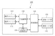
図1を参照すると、画像形成装置100は、複数の動作ユニット111、112、主電力供給部120、主制御部130、副制御部140、及び複数の通信インターフェース(interface:IF)部151、152を含む。
FIG. 1 is a block diagram showing an image forming apparatus according to the first embodiment of the present invention.
Referring to FIG. 1, an
画像形成装置100は、主電力供給部120から供給される電力により動作する装置として、節電のための待機モードでは動作ユニット111、112に供給される電力を遮断して主電力供給部120を完全にオフにすることで、画像形成装置100の消費電力を最小限化することができる。
The
活性化モードは、画像形成装置100が画像形成装置100として提供する固有機能を実行していたり、固有機能の実行が要請されると直ちに固有機能を行えるモードであり、待機モードは画像形成装置100が固有機能を実行せずに待機するモードとして本発明では、例えば、1W以下の低電力のみを消費する。
The activation mode is a mode in which a specific function provided by the
画像形成装置100は、画像データの生成、印刷、受信、転送等を行う装置として、プリンター、スキャナー、コピー機、ファクシミリ、複合機等を例として挙げられる。画像形成装置100で提供する低電力消費のための方式は、テレビ、コンピュータ、ノートパソコン等全ての電子製品に適用され得る。
The
複数の動作ユニット111、112は、例えば、印刷ユニット、コピーユニット、スキャンユニット、ADF(Auto Document Feeder)ユニット、フィニッシャ(Finisher)ユニット、HCF(High Capacity Feeder)ユニット、DCF(Double Capacity Feeder)ユニットのうちの一つでも良い。
The plurality of
主電力供給部120は、画像形成装置100が活性化モードである場合、複数の動作ユニット111、112、主制御部130、副制御部140、及び複数の通信IF部151、152に電力を供給し、待機モードである場合、複数の動作ユニット111、112と主制御部130に供給する電力を遮断する。
The main
主制御部130は、電力が供給される活性化モードで複数の動作ユニット111、112の動作を制御して各動作ユニット111、112で提供する機能を実行できるようにし、複数の通信IF部151、152及び副制御部140を介して中継されるデータをデータの特性に応じて処理する。例えば、通信IF部151及び副制御部140を介して入力されたデータが印刷するデータなら、主制御部130は印刷機能を行う動作ユニットにデータを転送して印刷されるようにする。
The
副制御部140は、主電力供給部120から主制御部130及び複数の動作ユニット111、112に供給される電力を遮断して主制御部130が待機モードに移行するようにし、接続された一つ以上の通信IF部151、152を介して受信されるデータを分析して活性化モードに切り替えるか否かを判断する。
The
例えば、予め設定された時間の間、複数の動作ユニット111、112が休止状態なら、主制御部130は待機モードに移行しなければならないものと判断してこれを副制御部140に通知し、副制御部140は主制御部130からの通知に従って、上記動作を行う。
なお、通信IF部151、152を介して受信されるデータが主制御部130の制御下で処理されなければならない場合、副制御部140は主電力供給部120が主制御部130及び複数の動作ユニット111、112に電力を供給して活性化モードに切り替えるようにする。
For example, if a plurality of
When data received via the communication IF
複数の通信IF部151、152は、副制御部140と通信できるように接続され、外部ソースから入力されるデータを主制御部130に直接入力せず、副制御部140を介して主制御部130に入力されるように設置される。これは、本発明の実施形態において待機モードと活性化モードをより効率良く切り替えて消費電力を最小化するためである。
The plurality of communication IF
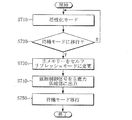
図2は、図1に示した画像形成装置の低電力制御方法を説明するためのフローチャートである。
図2を参照すると、画像形成装置100が正常に動作する活性化モードの状態で(ステップS210)、活性化モードから待機モードへの移行が必要かどうかを判断し(ステップS220)、待機モードへの移行が必要であるものと判断されると、主制御部130は副制御部140にこれを通知する。
FIG. 2 is a flowchart for explaining a low power control method of the image forming apparatus shown in FIG.
Referring to FIG. 2, in the state of the activation mode in which the
副制御部140は主制御部130からの通知によって、主制御部130及び複数の動作ユニット111、112に供給される電力を遮断するように主電力供給部120を制御する(ステップS230)。
これによって、画像形成装置100のモードは活性化モードから待機モードに移行する(ステップS240)。
待機モードに移行した後、副制御部140は複数の通信IF部151、152の内の一つを介して受信されるデータに応じて活性化モードに切り替えるか否かを判断する(ステップS250)。
The
As a result, the mode of the
After shifting to the standby mode, the
図3は、本発明の第2の実施形態に係る画像形成装置を示したブロック図である。
図3を参照すると、画像形成装置300は第1及び第2動作ユニット311、312、主電力供給部320、主制御部330、主メモリー340、ネットワークIF部351、PHY(Physical Layer Chip)チップ352、USB(Universal Serial Bus)IF部353、ウェイクアップ受信部354、ファックス送受信部355、低電力供給部360、副制御部370、及び副メモリー380を含む。
図3の各構成要素はバス(BUS)によって通信できるように接続され、主電力供給部320は各構成要素に電力を供給するために接続されるが、図面には示さない。
FIG. 3 is a block diagram showing an image forming apparatus according to the second embodiment of the present invention.
Referring to FIG. 3, the
3 are connected so as to communicate with each other via a bus (BUS), and the main
画像形成装置300、第1及び第2動作ユニット311、312、主電力供給部320、主制御部330及び副制御部370は、図1を参照して説明した複数の動作ユニット111、112、主電力供給部120、主制御部130及び副制御部140とほぼ同一であるため、詳細な説明は省略する。
第1及び第2動作ユニット311、312は2つ以上備えることができ、説明の便宜上、本実施形態では2つのみを示す。
The
Two or more first and
活性化モードで、主電力供給部320は、画像形成装置300の各構成要素に電力を供給する。
待機モードでは、主電力供給部320は、副制御部370に電力を供給する低電力供給部360が別途に設けられていない場合、第1及び第2動作ユニット311、312、主電力供給部320、主制御部330及び主メモリー340への電力供給を遮断して、ネットワークIF部351、PHYチップ352、USBIF部353、ウェイクアップ受信部354、ファックス送受信部355、副制御部370及び副メモリー380への電力供給は維持する。主電力供給部320は第1入出力(IO)部61を介して電力を供給する。
In the activation mode, the main
In the standby mode, the main
なお、待機モードで低電力供給部360が備えられている場合、主電力供給部320は第1及び第2動作ユニット311、312、主電力供給部320、主制御部330、主メモリー340、ネットワークIF部351、PHYチップ352、USBIF部353、ウェイクアップ受信部354、ファックス送受信部355、副制御部370及び副メモリー380への電力供給を遮断する。この時、低電力供給部360は副制御部370及び副メモリー380に電力を供給する。
When the low
以下では、待機モードに移行する以前の活性化モードについてまず説明する。
主制御部330は、電力を供給する活性化モードで第1及び第2動作ユニット311、312の動作を制御して、活性化モードを維持する。なお、予め設定された時間の間、画像形成装置300が動作しない場合、主制御部330は待機モードに移行しなければならないものと判断して、これを副制御部370に通知する。
Hereinafter, the activation mode before shifting to the standby mode will be described first.
The
主制御部330は、主MAC(Media Access Controller)331及び主USBデバイスモジュール332を含む。主MAC331は副制御部370のスイッチ30を介して第1MAC10又は第2MAC20とデータ通信する。主USBデバイスモジュール332は副制御部370のUSBホストモジュール50とデータ通信する。
The
主メモリー340は、画像形成装置300の電力がオンになって起動されると、画像形成装置300の駆動に必要な諸プログラムと画像形成装置300の状態情報をROM(read−only memory)(図示せず)からローディングして保存する。主メモリー340はRAM(random access memory)として例えば、DDRメモリーが挙げられるが、これに限らない。
When the
ネットワークIF部351は、通信IFとして外部ネットワークと通信するためのネットワークコネクタを提供する。ネットワークIF部351には例えば、ネットワークインターフェースカードが接続され、これによりネットワークを介してデータ送受信ができるようにし、インターネット機能を提供することができる。
The network IF
PHYチップ352は、ネットワークIF部351を介してネットワークから受信されるデータをOSI(Open Systems Interconnection)モデルの物理階層に対応するプロトコルを用いて第1MAC10に出力する。
The
USBIF部353は、USBデバイス又はUSBケーブルが接続されるコネクタとして、例えば、USBメモリー、パーソナルコンピュータ、ノートパソコン等多様なデバイスが接続されても良い。USBIF部353を介して外部から提供されるデータはUSBデバイスモジュール40に出力される。
The
ウェイクアップ受信部354は、画像形成装置300が待機モードである場合、ユーザーが人為的に活性化モードへの移行を要請するユーザーインターフェースとして、要請された信号を第2IO部62を介して副制御部370に出力する。ウェイクアップ受信部354は、画像形成装置300に備えられる物理的なボタンで実現されたり、遠隔制御器(図示せず)から入力される信号を受信するセンサーで実現することができる。
When the
ファックス送受信部355は、ファックス送受信を行う回路として、外部ファクシミリ(図示せず)からリング(ring)信号が受信されると、リング信号が受信されたことを第3IO部63を介して副制御部370に通知する。
When a ring signal is received from an external facsimile (not shown) as a fax transmission / reception circuit, the fax transmission /
低電力供給部360は選択的に備えられることができる。待機モードで主電力供給部320が副制御部370、副メモリー380及び構成要素(符号351〜355)にも電力を供給する場合、低電力供給部360は備えられなくても良い。一方、待機モードで主電力供給部320が副制御部370に電力を供給しない場合、低電力供給部360は備えられて副制御部370、副メモリー380及び前記構成要素351〜355に電力を供給する。
The low
以下では、低電力供給部360が備えられない場合を例として説明する。
副制御部370は、主制御部330から待機モードへの切り替えが要請されると、主電力供給部320から主制御部330及び第1及び第2動作ユニット311、312への電力供給を遮断して主制御部330が待機モードに移行するようにする。
なお、副制御部370は通信ができるように接続されたネットワークIF部351、USBIF部353、ウェイクアップ受信部354、又はファックス送受信部355により外部から受信されるデータを分析し、活性化モードに切り替えるか否かを判断する。
Below, the case where the low electric
When the
The
このために、副制御部370は、第1MAC10、第2MAC20、スイッチ30、USBデバイスモジュール40、USBホストモジュール50、(第1〜第3)IO部(61、62、63、)プロセッサ70、FIFO(First In First Out)部80、及びメモリー制御部90を含む。
For this purpose, the
第1MAC10は、ネットワークIF部351を介して受信されるデータをPHYチップ352を経由して受信し、通常のイーサネット(登録商標)MAC機能を行う。第1MAC10とPHYチップ352は、100Mbps転送のためのMII(Media Independent Interface)、1Gbps転送のためのGMII(Gigabit MII)、又はRGMII(Reduced GMII)によって接続されることができる。従って、第1MAC10はMII、GMII又はRGMII転送を支援することができる。
The
第1MAC10は、DMA(Direct Memory Access)機能を支援し、これによって、MII、GMII又はRGMIIによるデータを副制御部370の制御に従ってFIFO部80又は副メモリー380に出力する。以下では、副メモリー380に出力されて一時保存される場合を例えて説明する。
The
第2MAC20は、第1MAC10から出力されて副メモリー380に保存されたデータを読み出してスイッチ30に提供する。副メモリー380に保存されたデータの読み出しは、第2MAC20で支援するDMA機能によって行われることができる。
以下では、ネットワークIF部351、USBIF部353、ウェイクアップ受信部354及びファックス送受信部355を介して入力されるデータを主制御部に伝送してくれる機能を中継(relay)という。
The
Hereinafter, a function for transmitting data input via the network IF
スイッチ30は、第2MAC20から入力されるMII、GMII、又はRGMII形態のデータを主制御部330の主MAC331に中継し、この時、データの転送タイミングを調節する。このために、スイッチ30はスイッチ制御部31及びメモリー32を含む。スイッチ制御部31はMII、GMII、又はRGMII形態のデータをメモリー32に保存し、メモリー32に保存されたデータが主制御部330に直ちに転送されるように転送タイミングを制御する。
The switch 30 relays MII, GMII, or RGMII data input from the
実質的に、MII、GMII、又はRGMII形態のデータを主制御部330から副制御部370に転送するためには、図6に示すように2つ以上のPHYチップが必要であり、スイッチ30は2つ以上のPHYチップによって提供される機能を実行する。これによって、2つ以上のPHYチップの追加による材料費の増加及び電力消費を防止することができる。
In practice, in order to transfer data in the form of MII, GMII, or RGMII from the
USBデバイスモジュール40は、USBIF部353が外部から受信したデータが入力される。このために、USBデバイスモジュール40はUSBPHYチップ(図示せず)、USBデバイス(図示せず)及びDMA(図示せず)を含み、各機能は周知の技術であるため、詳細な説明は省略する。但し、USBIF部353の受信したデータはUSBPHYチップ(図示せず)を介して受信されて、USBデバイス(図示せず)及びDMA(図示せず)を介して副メモリー380に一時保存される。
The
USBホストモジュール50は、USBデバイスモジュール40の受信したデータを主USBデバイスモジュール332に中継する。このために、USBホストモジュール50はDMA(図示せず)、USBホスト(図示せず)及びUSBPHY(図示せず)を含み、各機能は周知の技術であるため、詳細な説明は省略する。但し、副メモリー380に一時保存されたデータはDMA(図示せず)によって読み出されて、USBホスト(図示せず)及びUSBPHYチップ(図示せず)を介して主制御部330にリレーされる。
The
(第1〜第3)IO部(61、62、63)は入出力インターフェースとして、入出力ピン又はケーブルコネクタ等で電力、信号、データ等を受信する。第1IO部61は、主電力供給部320と接続されて電力を提供され、主制御部330と接続されて多様な信号又はデータを受信する。第2IO部62は、ウェイクアップ受信部354と接続されて活性化モードへの切り替えを要請する信号を受信する。第3IO部63は、ファックス送受信部355と接続されてリング信号を受信し、外部のファクシミリから転送されるファックスデータを受信する。
The (first to third) IO units (61, 62, 63) receive power, signals, data, and the like through input / output pins or cable connectors as input / output interfaces. The
活性化モードで、プロセッサ70は、第1MAC10、USBデバイスモジュール40、第2及び第3IO部62、63から入力されるデータを分析し、主制御部330の制御によって処理されなければならないデータは主制御部330に中継し、副制御部370で処理可能なデータは自ら処理する。プロセッサ70は一例としてARM(Advanced RISC Machine)コアで実現することができる。
In the activation mode, the
なお、プロセッサ70は、主制御部330から待機モードへの切り替えを要請する信号が第1IO部61又はその他のIO部(図示せず)を介して受信されると、主電力供給部320に遮断制御信号を出力する。遮断制御信号は、主電力供給部320が主制御部330及び第1及び第2動作ユニット311、312に供給する電力を遮断するようにする信号である。これによって、主電力供給部320は、副制御部370及び副制御部370に接続された構成要素(符号351〜355、360、380)に最小限の電力を供給し、主制御部330と主制御部330に接続された構成要素(符号311、312、320、340)には電力を供給せずにオフにする。これによって、画像形成装置300は活性化モードから待機モードに移行することになる。
The
一方、主制御部330は、主制御部330と通信する主メモリー340をセルフリフレッシュ(Self−refresh)モードに変更し、これを指示する信号を第1IO部61を介して副制御部370に通知して待機モードへの切り替えを要請する。プロセッサ70は前記信号が受信されると、上述の遮断制御信号を低電力供給部360に出力して待機モードに移行する。セルフリフレッシュは、低電力消費等の目的のために外部から制御信号なしに内部でリフレッシュ要求信号及び制御信号を発生して、内部で生成されたアドレスによってリフレッシュ動作を実行するものである。
On the other hand, the
FIFO部80又は副メモリー380は、ネットワークIF部351、USBIF部353、ウェイクアップ受信部354又はファックス送受信部355を介して受信されるデータを一時保存する。
上記構成要素(符号351、353〜355)を介して受信されるデータを副メモリー380に一時保存するように設定された場合、メモリー制御部90は受信されたデータを副メモリー380に保存し、データ中継の際、副メモリー380に保存されたデータを読み出して第2MAC20又はUSBホストモジュール50に出力する。
The
When data received via the above components (
なお、メモリー制御部90は、画像形成装置300の電源がオンになって起動されると、上述のROM(図示せず)に保存された画像形成装置300の状態情報、待機モード駆動に必要なシステムプログラム、ウェイクアップ条件等をローディングして副メモリー380に保存する。画像形成装置300の状態情報は、例えば、トナー残量、ジョブの進行程度等の画像形成装置300の状態に関した情報でも良い。副制御部370又はプロセッサ70は、保存されたシステムプログラムを用いて活性化モード及び待機モードで画像形成装置300の一部動作を制御する。
When the
以下では、待機モードから活性化モードに切り替える工程についてまず説明する。
画像形成装置300が待機モードに移行すると、副制御部370は主電力供給部320又は低電力供給部360から供給される最小限の電力で駆動を維持する。
待機モードに移行した後、構成要素(符号351、353〜355)を介してデータが受信されると、プロセッサ70は受信されたデータを分析して、受信されたデータがウェイクアップ条件に該当するか、又は自ら処理可能であるかを判断する。
In the following, the process of switching from the standby mode to the activation mode will be described first.
When the
After the transition to the standby mode, when data is received via the components (
待機モードの状態で構成要素(符号351、353〜355)を介して受信されるデータが主制御部330で処理されなければならないと判断されると、これはウェイクアップ条件に該当する。
ウェイクアップ条件の例としては、受信されたデータがファックスリング信号であるか、ウェイクアップ受信部354の選択信号であるか印刷要請信号であるか、又はカバーオープン検出信号、トレイオープン検出信号、マウスクリック信号等様々である。
If it is determined that data received via the components (
Examples of wake-up conditions include whether the received data is a fax ring signal, a selection signal of the wake-up receiving
受信されたデータがウェイクアップ条件に該当する場合、プロセッサ70は活性化モードへの切り替えが必要であるものと判断し、第1IO部61を制御して主電力供給部320に供給制御信号を出力する。供給制御信号は、主電力供給部320が第1及び第2動作ユニット311、312、主制御部330及び主メモリー340に電力を供給するように指示する信号である。これによって、画像形成装置300は待機モードから活性化モードに切り替わる。
If the received data satisfies the wake-up condition, the
第一に、待機モードの状態で、ネットワークIF部351を介して受信されるデータ(以下、「ネットワークデータ」という)を中継する場合について説明する。ネットワークデータは、ネットワークIF部351及びPHYチップ352を経由して第1MAC10に入力される。
プロセッサ70は、第1MAC10で入力されたネットワークデータをFIFO部80又は副メモリー380に保存し、ネットワークデータを分析してウェイクアップ条件に該当するかを判断する。即ち、プロセッサ70は活性化モードへの切り替えが必要であるか否かを判断する。活性化モードへの切り替えが必要であるものと判断されると、プロセッサ70は主電力供給部320を制御して画像形成装置300に電力を供給するようにする。
First, a case where data received through the network IF unit 351 (hereinafter referred to as “network data”) is relayed in the standby mode will be described. The network data is input to the
The
活性化モードに切り替えられると、第2MAC20はFIFO部80又は副メモリー380に保存されたネットワークデータを読み出してスイッチ30に提供する。スイッチ30は、ネットワークデータを主制御部330の主MAC331に転送するがこの時、データ同期を取って転送する。主MAC331からネットワークIF部351へのデータ転送ルートは、上述の過程と逆である。
When switched to the activation mode, the
第二に、待機モードの状態でUSBIF部353を介して受信されるデータ(以下、「USBデータ」という)を中継する場合について説明する。
USBデータはUSBIF部353に接続された外部機器から入力されてプロセッサ70の制御によってFIFO部80又は副メモリー380に保存される。
Secondly, a case where data (hereinafter referred to as “USB data”) received via the
The USB data is input from an external device connected to the
プロセッサ70は、USBデータを分析して活性化モードへの切り替えが必要であるか否かを判断する。活性化モードへの切り替えが必要であるものと判断されると、プロセッサ70は主電力供給部320を制御して画像形成装置300に電力を供給するようにする。活性化モードに切り替わると、USBホストモジュール50はFIFO部80又は副メモリー380に保存されたUSBデータを読み出して主USBデバイスモジュール332に中継する。主USBデバイスモジュール332からUSBIF部353へのデータ転送ルートは、上述のと逆である。
The
第三に、待機モードの状態でウェイクアップ受信部354を介して受信されるデータ(以下、「ウェイクアップデータ」という)を中継する場合について説明する。
ウェイクアップデータは活性化モードへの切り替えを要請する直接的な信号であるため、プロセッサ70はウェイクアップデータをFIFO部80又は副メモリー380に保存し、主電力供給部320を制御して画像形成装置300に電力を供給するようにする。これによって、画像形成装置300は活性化モードに切り替わる。活性化モードに切り替わると、プロセッサ70は保存されたウェイクアップデータを読み出して第1IO部61を介して主制御部330に中継する。
Third, a case where data received via the wake-up receiving
Since the wake-up data is a direct signal for requesting switching to the activation mode, the
第四に、待機モードの状態でファックス送受信部355を介して受信されるデータ(以下、「ファックスデータ」という)を中継する場合について説明する。
ファックス送受信部355と通信できるように接続された外部ファクシミリは転送するファックスデータをファックス送受信部355に転送する。ファックスデータはリング信号とスキャンされて印刷される実際のデータを含む。ファックス送受信部355は転送されたリング信号を第2IO部62を介して副制御部370に提供し、プロセッサ70はリング信号はウェイクアップ条件に符合する信号であるため、主電力供給部320を制御して画像形成装置300に電力を供給するようにする。
Fourthly, a case where data (hereinafter referred to as “fax data”) received via the fax transmission /
The external facsimile connected so as to be able to communicate with the fax transmission /
これによって、活性化モードに切り替わると、ファックス送受信部355は外部ファクシミリから実際データを受信し、プロセッサは実際データをFIFO部80又は副メモリー380に保存し、第3IO部63を介して主制御部330にリレーする。主制御部330はリレーされた実際のデータをスキャン及び印刷するように該当動作ユニット(例えば、311)を制御する。
As a result, when switching to the activation mode, the fax transmission /
図4は、本発明の第3の実施形態に係る画像形成装置を示したブロック図である。
図4を参照すると、画像形成装置400は、第1及び第2動作ユニット411、412、主電力供給部420、主制御部430、主メモリー440、ネットワークIF部451、PHYチップ452、USBIF部453、低電力供給部460、副制御部470、及び副メモリー480を含む。
画像形成装置400の各構成要素は図3に示した画像形成装置300の各構成要素とほぼ同一であるため、詳細な説明は省略する。なお、説明の便宜上、ウェイクアップ受信部354、ファックス送受信部355、第2及び第3IO部62、63の図示は省略する。
FIG. 4 is a block diagram showing an image forming apparatus according to the third embodiment of the present invention.
Referring to FIG. 4, the
Each component of the
但し、図4に示した主制御部430は、主MAC331を含まずに、副制御部470は第2MAC20とスイッチ30を含まない。
従って、ネットワークIF部451を介して受信されるネットワークデータは第1MAC471、メモリー制御部477、副メモリー480、USBホストモジュール473を経由して主制御部430の主USBデバイスモジュール431に中継される。中継工程は、副制御部470又はプロセッサ475によって制御される。
However, the
Accordingly, network data received via the network IF
具体的に説明すると、待機モードでネットワークデータは、ネットワークIF部451、PHYチップ452、第1MAC471及びメモリー制御部477を経由して副メモリー480に一時保存され、ネットワークIF部451、PHYチップ452及び第1MAC471を経由してFIFO部476に一時保存される。
More specifically, network data is temporarily stored in the
プロセッサ475は、ネットワークデータが主制御部430の制御によって処理されなければならないデータなら、画像形成装置400を活性化モードに切り替える。活性化モードに切り替わると、USBホストモジュール473はFIFO部476又は副メモリー480に保存されたネットワークデータを読み出して主USBデバイスモジュール431に中継する。
USBIF部453を介して受信されるUSBデータの中継は、図3を参照して説明したものと同一である。
If the network data is data that must be processed under the control of the
The relay of USB data received via the
図5は、本発明の第4の実施形態に係る画像形成装置を示したブロック図である。
図5を参照すると、画像形成装置500は、第1及び第2動作ユニット511、512、主電力供給部520、主制御部530、主メモリー540、ネットワークIF部551、PHYチップ552、USBIF部553、低電力供給部560、副制御部570、及び副メモリー580を含む。
画像形成装置500の各構成要素は、図3に示した画像形成装置300の各構成要素とほぼ同一であるため、詳細な説明は省略する。なお、説明の便宜上、ウェイクアップ受信部354、ファックス送受信部355、第2及び第3IO部62、63の図示は省略する。
FIG. 5 is a block diagram showing an image forming apparatus according to the fourth embodiment of the present invention.
Referring to FIG. 5, the
Each component of the
但し、図5に示した主制御部530は、主USBデバイスモジュール332を含まずに、副制御部570はUSBホストモジュール50を含まない。従って、USBIF部553を介して受信されるUSBデータはUSBデバイスモジュール574、メモリー制御部578、副メモリー580、第2MAC572、及びスイッチ573を経由して主MAC531に中継される。中継行程は、副制御部570又はプロセッサ576によって制御される。
However, the
具体的に説明すると、待機モードでUSBデータは、FIFO部577に一時保存されるか、又はUSBデバイスモジュール574及びメモリー制御部578を経由して副メモリー580に一時保存される。
プロセッサ576はUSBデータが主制御部530の制御によって処理されなけれなならないデータなら、画像形成装置500を活性化モードに切り替える。活性化モードに切り替わると、第2MAC531は一時保存されたUSBデータを読み出してスイッチ573に中継し、スイッチ573は転送タイミングに合わせてUSBデータを主MAC531に中継する。
ネットワークIF部551を介して受信されるネットワークデータの中継は、図3を参照して説明したものと同一である。
More specifically, USB data is temporarily stored in the
If the USB data is data that must be processed under the control of the
The relay of network data received via the network IF
図6は、本発明の第5の実施形態に係る画像形成装置を示したブロック図である。
図6を参照すれば、画像形成装置600は、図3に示した副制御部370のスイッチ30に代って2つのPHYチップ(390、385)を含む。2つのPHYチップ(390、385)は、MII、GMII、又はRGMII形態のデータを第2MAC20から主MAC331に中継するが、データ同期を取って中継する。2つのPHYチップ(390、385)は、図5の場合にも主制御部530と副制御部570の間に備えることができ、この場合、スイッチ573は備えない。
FIG. 6 is a block diagram showing an image forming apparatus according to the fifth embodiment of the present invention.
Referring to FIG. 6, the
図7は、図3に示した画像形成装置の低電力制御方法のうち、活性化モードから待機モードに切り替える工程を説明するためのフローチャートである。
図7を参照すると、画像形成装置300が正常に動作する活性化モードの状態で(ステップS710)、主制御部330は活性化モードから待機モードへの移行が必要かどうかを判断し(ステップS720)、待機モードへの移行が必要であるものと判断されると、主メモリー340をセルフリフレッシュモードに変更し、副制御部370に主メモリー340がセルフリフレッシュモードに変更されたことを通知する(ステップS730)。
FIG. 7 is a flowchart for explaining a step of switching from the activation mode to the standby mode in the low power control method for the image forming apparatus shown in FIG.
Referring to FIG. 7, in the state of the activation mode in which the
副制御部370は、ステップS730の通知によって、主制御部330が待機モードに移行する準備が完了したものと判断し、遮断制御信号を主電力供給部320に出力する(ステップS740)。
主電力供給部320は、遮断制御信号によって主制御部330及び複数の動作ユニット311、312に供給される電力を遮断し、これにより画像形成装置300は待機モードに移行する(ステップS750)。これによって、副制御部370及び副制御部370に接続された構成要素(符号351〜355、380)のみに電力が供給されて画像形成装置300は最小限の電力を消費することになる。
Based on the notification in step S730, the
The main
図8は、図3に示した画像形成装置の低電力制御方法のうち、待機モードから活性化モードに切り替える工程を説明するためのフローチャートである。
図8を参照すると、画像形成装置300は節電モードである待機モードの状態にある(ステップS810)。
FIG. 8 is a flowchart for explaining a step of switching from the standby mode to the activation mode in the low power control method of the image forming apparatus shown in FIG.
Referring to FIG. 8, the
副制御部370は外部からデータが入力されると(ステップS820)、データを分析して活性化モードに切り替えるか否かを判断する(ステップS830)。ステップS820で入力されるデータはネットワークIF部351、USBIF部353、ウェイクアップ受信部354、又はファックス送受信部355を介して入力される。
ステップS830で副制御部370は入力されたデータをFIFO部80又は副メモリー380に一時保存し、入力されたデータがウェイクアップ条件に符合する信号であるかどうかを判断する(ステップS840)。即ち、副制御部370は入力されたデータが副制御部370で処理可能であるか、又は主制御部330で処理されなければならないかどうかを判断する。
When data is input from the outside (step S820), the
In step S830, the
副制御部370で処理可能であると判断された場合、副制御部370は待機モードを維持し、副メモリー380に保存された情報を用いてデータを処理する(ステップS850)。例えば、入力されたデータが画像形成装置300の状態を問い合わせる場合、プロセッサ70は副メモリー380に保存された当該状態情報を検索して応答する。
一方、ステップS840で入力されたデータがウェイクアップ条件に符合する信号であると判断された場合、副制御部370は供給制御信号を主電力供給部320に出力する(ステップS860)。
If it is determined that the
On the other hand, when it is determined that the data input in step S840 is a signal that matches the wake-up condition, the
主電力供給部320は供給制御信号によって、主メモリー340のセルフリフレッシュモードを解除し(ステップS870)、主制御部330及び主制御部330に接続された構成要素(符号311、312、340)に電力を供給して活性化モードに切り替える(ステップS880)。
活性化モードに切り替えられると副制御部370はFIFO部80又は副メモリー380に一時保存されたデータを主制御部330に中継し、主制御部330は中継されたデータを処理するように当該動作ユニットを制御する(ステップS890)。
In response to the supply control signal, the main
When switched to the activation mode, the
ステップS890において、中継は、図3を参照して説明したため、ネットワークデータの中継、USBデータの中継、ウェイクアップ受信部354から入力されたデータの中継、及びファックスデータの中継に関する具体的な説明は省略する。
なお、上述の図8の工程は、図4〜図6に示した画像形成装置400、500、600についても適用することができる。
Since the relay has been described with reference to FIG. 3 in step S890, specific descriptions regarding the relay of network data, the relay of USB data, the relay of data input from the wake-up receiving
The above-described process of FIG. 8 can also be applied to the
図9は、本発明の第6の実施形態に係る画像形成装置を示したブロック図である。
図9を参照すると、画像形成装置900は、主電力供給部910、動作パネル部920、画像処理部930、画像形成部940、主メモリー950、主制御部960、ネットワークIF部971、USBIF部972、ウェイクアップ受信部973、ファックス送受信部974、副メモリー980、及び副制御部990を含む。
FIG. 9 is a block diagram showing an image forming apparatus according to the sixth embodiment of the present invention.
Referring to FIG. 9, the
本実施形態で、主電力供給部910、主メモリー950、主制御部960、ネットワークIF部551、USBIF部972、ウェイクアップ受信部973、ファックス送受信部974、副メモリー980、及び副制御部990の動作は、図3〜図6を参照して説明した各構成要素とほぼ同一であるため、詳細な説明は省略する。
In this embodiment, the main
動作パネル部920は、ユーザーインターフェースとして、ユーザーからユーザー命令が入力される複数の機能キー、タッチスクリーン等を含み、画像形成装置900の状態を表示する表示パネルを含む。
画像処理部930は、印刷データ、スキャニングデータ、又はファックスデータを各機能に適合したフォーマットに処理する。例えば、印刷データの場合、画像処理部930は印刷データを該当エミュレータを用いてビットマップデータに切り替える。印刷データは例えば、USBIF部972を介して接続されたパーソナルコンピュータから入力され、ファックスデータはファックス送受信部974を介して入力される。
The
The
画像形成部940は、画像処理部930で処理されたデータから画像を形成する。例えば、画像形成部940はスキャナー(図示せず)又は印刷エンジン部(図示せず)を備える場合、画像形成部940はデータをスキャニングするか、用紙上に印刷又はコピーをする。
主メモリー950は、画像形成装置900の機能を実現するのに必要な各種プログラム、画像形成装置900の動作遂行中に発生する各種データ、画像形成装置900の状態情報等を保存し、これは、ROM又はRAMでも良い。
The
The main memory 950 stores various programs necessary for realizing the functions of the
主制御部960は、保存された制御プログラムに従って画像形成装置900の全般の動作を制御する。例えば、ファックス送受信部974を介してリング信号が受信されて副制御部990の制御によって活性化モードに切り替えられると、主制御部960はファックス送受信部974及び副制御部990を介して中継されるファックスデータをスキャニングして印刷するように画像形成部940を制御する。
The
尚、本発明は、上述の実施形態に限られるものではない。本発明の技術的範囲から逸脱しない範囲内で多様に変更実施することが可能である。 The present invention is not limited to the embodiment described above. Various modifications can be made without departing from the technical scope of the present invention.
10、471、571 第1MAC
20、572 第2MAC
30、573 スイッチ
31 スイッチ制御部
32 メモリー
40、472、574 USBデバイスモジュール
50、473 USBホストモジュール
61、62、63 (第1〜第3)IO部
474、575 第1IO部
70、475、576 プロセッサ
80、476、577 FIFO部
90、477、578 メモリー制御部
100、300、400、500、600、900 画像形成装置
111、112 動作ユニット
311、312、411、412、511、512 (第1及び第2)動作ユニット
120、320、420、520、910 主電力供給部
130、330、430、530、960 主制御部
140、370、470、570、990 副制御部
151、152 通信インターフェース部
331、531 主MAC
332、431 主USBデバイスモジュール
340、440、540、950 主メモリー
351、451、551、971 ネットワークIF部
352、390、395、452、552 PHYチップ
353、453、553、972 USBIF部
354、973 ウェイクアップ受信部
355、974 ファックス送受信部
360、460、560 低電力供給部
380、480、580、980 副メモリー
920 動作パネル部
930 画像処理部
940 画像形成部
10, 471, 571 1st MAC
20, 572 Second MAC
30, 573 switch 31
332, 431 Main
Claims (15)
電力を供給する主電力供給部と、
前記電力が供給される活性化モードで前記複数の動作ユニットを制御する主制御部と、
少なくとも一つ以上の通信インターフェース部と、
前記主電力供給部から前記主制御部及び前記動作ユニットへの電力供給を遮断して前記主制御部が待機モードに移行するようにし、接続された前記少なくとも一つ以上の通信インターフェース部によって受信されるデータを分析して前記待機モードから前記活性化モードに切り替えるか否かを判断する副制御部とを有することを特徴とする画像形成装置。 In an image forming apparatus including a plurality of operation units,
A main power supply for supplying power;
A main control unit that controls the plurality of operation units in an activation mode in which the power is supplied;
At least one communication interface unit;
The power supply from the main power supply unit to the main control unit and the operation unit is cut off so that the main control unit shifts to a standby mode, and is received by the at least one communication interface unit connected. And a sub-control unit that determines whether or not to switch from the standby mode to the activation mode.
前記第1MACを介して受信されたデータを分析して前記待機モードから前記活性化モードへの切り替えが必要であるものと判断されると、前記主制御部に前記電力を供給するように前記主電力供給部を制御するプロセッサと、
前記待機モードから前記活性化モードに切り替えられると、前記第1MACで受信されたデータを前記主制御部に中継する第2MACとを含むことを特徴とする請求項1に記載の画像形成装置。 The sub control unit includes a first MAC (Media Access Controller) that receives data input through the communication interface unit;
When the data received through the first MAC is analyzed and it is determined that switching from the standby mode to the activation mode is necessary, the main controller is configured to supply the power to the main control unit. A processor that controls the power supply;
The image forming apparatus according to claim 1, further comprising: a second MAC that relays data received by the first MAC to the main control unit when the standby mode is switched to the activation mode.
前記待機モードから前記活性化モードに切り替えられた時、前記USBデバイス部を介して受信されるデータを前記主制御部に中継するUSBホスト部とを更に含み、
前記プロセッサは、前記USBデバイス部を介して受信されたデータを分析して前記待機モードから前記活性化モードに切り替えるか否かを判断することを特徴とする請求項1又は2に記載の画像形成装置。 The sub-control unit includes a USB device unit that receives data via the communication interface unit,
A USB host unit that relays data received via the USB device unit to the main control unit when the standby mode is switched to the activation mode;
The image formation according to claim 1, wherein the processor analyzes data received through the USB device unit and determines whether to switch from the standby mode to the activation mode. apparatus.
前記受信されたデータを分析して前記待機モードから前記活性化モードへの切り替えが必要であるものと判断されると、前記主制御部に前記電力を供給するように前記主電力供給部を制御するプロセッサと、
前記待機モードから前記活性化モードに切り替えられると、前記MACを介して受信されたデータを前記主制御部に中継するUSBホスト部とを含むことを特徴とする請求項1に記載の画像形成装置。 The sub-control unit receives data via one of the communication interface units; and
When the received data is analyzed and it is determined that switching from the standby mode to the activation mode is necessary, the main power supply unit is controlled to supply the power to the main control unit. A processor to
The image forming apparatus according to claim 1, further comprising: a USB host unit that relays data received via the MAC to the main control unit when the standby mode is switched to the activation mode. .
前記プロセッサは、前記USBデバイス部を介して受信されたデータを分析して前記待機モードから前記活性化モードに切り替えるか否かを判断し、前記待機モードから前記活性化モードに切り替えられると、前記USBホスト部は前記USBデバイス部を介して受信されたデータを前記主制御部に中継することを特徴とする請求項5に記載の画像形成装置。 The sub-control unit further includes a USB device unit that receives data via another one of the communication interface units,
The processor analyzes data received via the USB device unit to determine whether to switch from the standby mode to the activation mode, and when switched from the standby mode to the activation mode, 6. The image forming apparatus according to claim 5, wherein the USB host unit relays data received via the USB device unit to the main control unit.
前記受信されたデータを分析して前記待機モードから前記活性化モードへの切り替えが必要であるものと判断されると、前記主制御部に前記電力を供給するように前記主電力供給部を制御するプロセッサと、
前記待機モードから前記活性化モードに切り替えられると、前記USBデバイス部を介して受信されたデータを前記主制御部に中継するデータ出力MACとを含むことを特徴とする請求項1に記載の画像形成装置。 The sub-control unit includes a USB device unit that receives data via one of the communication interface units;
When the received data is analyzed and it is determined that switching from the standby mode to the activation mode is necessary, the main power supply unit is controlled to supply the power to the main control unit. A processor to
2. The image according to claim 1, further comprising: a data output MAC that relays data received via the USB device unit to the main control unit when the standby mode is switched to the activation mode. 3. Forming equipment.
前記プロセッサは、前記データ入力MACを介して受信されたデータを分析して前記待機モードから前記活性化モードに切り替えるか否かを判断し、前記待機モードから前記活性化モードに切り替えられると、前記データ出力MACは前記データ入力MACを介して受信されたデータを前記主制御部に中継することを特徴とする請求項7に記載の画像形成装置。 The sub-control unit further includes a data input MAC for receiving data via another one of the communication interface units,
The processor analyzes data received via the data input MAC to determine whether to switch from the standby mode to the activation mode, and when switched from the standby mode to the activation mode, The image forming apparatus according to claim 7, wherein the data output MAC relays data received via the data input MAC to the main control unit.
活性化モードで前記複数の動作ユニットを制御する前記主制御部に前記主電力供給部から電力を供給するステップと、
前記副制御部によって、前記主電力供給部から前記主制御部及び前記動作ユニットへの電力供給を遮断して待機モードに移行するステップと、
前記副制御部に接続された少なくとも一つ以上の通信インターフェース部を介して受信されたデータを分析して前記待機モードから前記活性化モードに切り替えるか否かを判断するステップとを有することを特徴とする画像形成装置の低電力制御方法。 In a low power control method of an image forming apparatus including a main power supply unit, a main control unit, a sub control unit, and a plurality of operation units,
Supplying power from the main power supply unit to the main control unit that controls the plurality of operation units in an activation mode;
Shutting off the power supply from the main power supply unit to the main control unit and the operation unit by the sub-control unit and shifting to a standby mode;
Analyzing data received through at least one communication interface unit connected to the sub-control unit and determining whether to switch from the standby mode to the activation mode. A low power control method for an image forming apparatus.
前記第1MACを介して受信したデータを分析して前記待機モードから前記活性化モードへの切り替えが必要であるものと判断されると、前記主制御部に前記電力を供給して前記待機モードから前記活性化モードに切り替えるステップと、
前記第1MACを介して受信したデータを第2MACを介して前記主制御部に中継するステップとを含むことを特徴とする請求項9に記載の画像形成装置の低電力制御方法。 The step of determining whether to switch from the standby mode to the activation mode includes receiving data input from the communication interface unit by a first MAC (Media Access Controller);
If it is determined that switching from the standby mode to the activation mode is necessary by analyzing the data received via the first MAC, the power is supplied to the main control unit from the standby mode. Switching to the activation mode;
The low power control method for an image forming apparatus according to claim 9, further comprising: relaying data received via the first MAC to the main control unit via the second MAC.
前記待機モードから前記活性化モードに切り替えられると、USBホスト部によって、前記USBデバイス部を介して受信されたデータを前記主制御部に中継するステップとを更に含むことを特徴とする請求項9に記載の画像形成装置の低電力制御方法。 The step of determining whether to switch from the standby mode to the activation mode includes receiving data input from one of the communication interface units by a USB device unit;
10. The method according to claim 9, further comprising the step of relaying data received via the USB device unit to the main control unit by the USB host unit when the standby mode is switched to the activation mode. 2. A low power control method for an image forming apparatus according to 1.
前記MACを介して受信したデータを分析して前記待機モードから前記活性化モードへの切り替えが必要であるものと判断されると、前記主制御部に前記電力を供給して前記待機モードから前記活性化モードに切り替えるステップと、
前記MACを介して受信したデータをUSBホスト部により前記主制御部に中継するステップとを含むことを特徴とする請求項9に記載の画像形成装置の低電力制御方法。 The step of determining whether to switch from the standby mode to the activation mode includes receiving data input from one of the communication interface units by the MAC,
When it is determined that switching from the standby mode to the activation mode is necessary by analyzing the data received via the MAC, the power is supplied to the main control unit from the standby mode. Switching to activation mode;
10. The low power control method for an image forming apparatus according to claim 9, further comprising a step of relaying data received via the MAC to the main control unit by a USB host unit.
前記USBデバイス部を介して受信したデータを分析して前記待機モードから前記活性化モードへの切り替えが必要であるものと判断されると、前記主電力供給部が前記主制御部に前記電力を供給して前記待機モードから前記活性化モードに切り替えるステップと、
前記USBデバイス部を介して受信したデータをデータ出力MACを介して前記主制御部に中継するステップとを含むことを特徴とする請求項9に記載の画像形成装置の低電力制御方法。 The step of determining whether to switch from the standby mode to the activation mode includes receiving data input via one of the communication interface units by a USB device unit;
When the data received via the USB device unit is analyzed and it is determined that switching from the standby mode to the activation mode is necessary, the main power supply unit supplies the power to the main control unit. Supplying and switching from the standby mode to the activation mode;
The low power control method for an image forming apparatus according to claim 9, further comprising: relaying data received via the USB device unit to the main control unit via a data output MAC.
前記待機モードから前記活性化モードに切り替えられると、前記データ出力MACは前記データ入力MACにより受信したデータを前記主制御部に中継することを特徴とする請求項14に記載の画像形成装置の低電力制御方法。
The step of determining whether to switch from the standby mode to the activation mode further includes receiving data input via another one of the communication interface units by a data input MAC.
15. The image forming apparatus according to claim 14, wherein when the standby mode is switched to the activation mode, the data output MAC relays data received by the data input MAC to the main control unit. Power control method.
Applications Claiming Priority (1)
| Application Number | Priority Date | Filing Date | Title |
|---|---|---|---|
| KR1020090067626A KR101158715B1 (en) | 2009-07-24 | 2009-07-24 | Image forming apparatus and method for controlling lower power thereof |
Publications (2)
| Publication Number | Publication Date |
|---|---|
| JP2011025671A true JP2011025671A (en) | 2011-02-10 |
| JP2011025671A5 JP2011025671A5 (en) | 2012-04-19 |
Family
ID=43443355
Family Applications (1)
| Application Number | Title | Priority Date | Filing Date |
|---|---|---|---|
| JP2010114159A Pending JP2011025671A (en) | 2009-07-24 | 2010-05-18 | Image forming device, and low electric power control method therefor |
Country Status (5)
| Country | Link |
|---|---|
| US (1) | US20110019225A1 (en) |
| EP (1) | EP2293147B1 (en) |
| JP (1) | JP2011025671A (en) |
| KR (1) | KR101158715B1 (en) |
| CN (1) | CN101964852A (en) |
Cited By (1)
| Publication number | Priority date | Publication date | Assignee | Title |
|---|---|---|---|---|
| JP2015208877A (en) * | 2014-04-24 | 2015-11-24 | 京セラドキュメントソリューションズ株式会社 | Information processor |
Families Citing this family (28)
| Publication number | Priority date | Publication date | Assignee | Title |
|---|---|---|---|---|
| US8160725B2 (en) * | 2009-05-20 | 2012-04-17 | Vega Grieshaber Kg | Energy saving control for a field device |
| US9141574B2 (en) * | 2009-09-09 | 2015-09-22 | Samsung Electronics Co., Ltd. | Image forming apparatus and low power driving method thereof |
| KR101569030B1 (en) * | 2009-10-14 | 2015-11-16 | 삼성전자주식회사 | Image forming apparatus and method for connecting network of thereof |
| KR101706773B1 (en) * | 2009-10-20 | 2017-02-14 | 에스프린팅솔루션 주식회사 | Image forming apparatus and control method thereof |
| CN102263874B (en) * | 2010-05-28 | 2014-03-12 | 京瓷办公信息系统株式会社 | Image forming apparatus having power saving mode |
| TW201227260A (en) * | 2010-12-22 | 2012-07-01 | Ralink Technology Corp | Usb system and power management module and method thereof |
| US9015509B2 (en) * | 2011-02-07 | 2015-04-21 | Silicon Image, Inc. | Mechanism for low power standby mode control circuit |
| KR20130006167A (en) * | 2011-07-08 | 2013-01-16 | 삼성전자주식회사 | Image display apparatus and method for controlling the image display apparatus |
| JP5836207B2 (en) * | 2011-07-25 | 2015-12-24 | 京セラドキュメントソリューションズ株式会社 | Image forming apparatus |
| US20130132740A1 (en) * | 2011-11-23 | 2013-05-23 | O2Micro, Inc. | Power Control for Memory Devices |
| KR102012436B1 (en) * | 2012-09-17 | 2019-08-20 | 휴렛-팩커드 디벨롭먼트 컴퍼니, 엘.피. | Image forming apparatus, driving method thereof, and computer-readable recording medium |
| CN103777973A (en) * | 2012-10-24 | 2014-05-07 | 英业达科技有限公司 | Computer device and arousing method thereof |
| KR102094902B1 (en) * | 2013-07-08 | 2020-03-30 | 삼성전자주식회사 | Storage system and ufs system changing interface mode in active state |
| JP6078453B2 (en) | 2013-10-31 | 2017-02-08 | 京セラドキュメントソリューションズ株式会社 | Image forming apparatus |
| CN103634666A (en) * | 2013-12-09 | 2014-03-12 | 乐视致新电子科技(天津)有限公司 | Method and system for protecting intelligent television in power-on state |
| CN104753619A (en) * | 2013-12-27 | 2015-07-01 | 上海仪电数字技术有限公司 | Handheld device and emergency broadcast receiving method |
| US9299194B2 (en) | 2014-02-14 | 2016-03-29 | Osterhout Group, Inc. | Secure sharing in head worn computing |
| US9401540B2 (en) | 2014-02-11 | 2016-07-26 | Osterhout Group, Inc. | Spatial location presentation in head worn computing |
| KR101595933B1 (en) * | 2014-08-13 | 2016-02-26 | 코스텔(주) | Intelligent Information Apparatus |
| KR20160041282A (en) * | 2014-10-07 | 2016-04-18 | 삼성전자주식회사 | Electronic device and controlling method thereof |
| KR102246120B1 (en) * | 2014-11-21 | 2021-04-29 | 삼성전자주식회사 | User terminal for controlling display apparatus and control method thereof |
| US10069718B2 (en) * | 2015-11-26 | 2018-09-04 | Dell Products, L.P. | Switching of host network traffic through baseboard management controller (BMC) |
| KR20170111218A (en) * | 2016-03-25 | 2017-10-12 | 엘에스산전 주식회사 | Slave module for monitoring electric system |
| US10536739B2 (en) * | 2017-01-04 | 2020-01-14 | Samsung Electronics Co., Ltd. | Display apparatus and control method thereof |
| JP6647257B2 (en) * | 2017-09-06 | 2020-02-14 | キヤノン株式会社 | Printing apparatus, control method thereof, and program |
| KR20190001686U (en) | 2017-12-26 | 2019-07-04 | 권오익 | Dog muzzle |
| CN108446139B (en) * | 2018-03-26 | 2021-11-16 | 京东方科技集团股份有限公司 | Awakening method and device for FPGA chip |
| JP2020179622A (en) * | 2019-04-26 | 2020-11-05 | セイコーエプソン株式会社 | Printing device and printing device control method |
Family Cites Families (23)
| Publication number | Priority date | Publication date | Assignee | Title |
|---|---|---|---|---|
| KR960010183B1 (en) | 1993-10-23 | 1996-07-26 | 김광호 | Image recording apparatus and control method thereof for energy economization |
| US5834857A (en) * | 1994-04-15 | 1998-11-10 | Canon Kabushiki Kaisha | Power supply device for communication apparatus |
| KR0149263B1 (en) * | 1995-03-31 | 1998-10-15 | 김광호 | Personal computer unified with printer system |
| JP3649920B2 (en) * | 1998-10-09 | 2005-05-18 | シャープ株式会社 | Image forming apparatus |
| US6460143B1 (en) * | 1999-05-13 | 2002-10-01 | Apple Computer, Inc. | Apparatus and method for awakening bus circuitry from a low power state |
| FI20011881A (en) * | 2001-09-25 | 2003-03-26 | Nokia Corp | Method of starting a base station's distributed processor architecture and a base station |
| JP4546040B2 (en) * | 2003-05-12 | 2010-09-15 | キヤノン株式会社 | Network service system, service agent processing method, computer-readable storage medium storing program, and program |
| JP4444710B2 (en) * | 2004-03-26 | 2010-03-31 | キヤノン株式会社 | Image processing apparatus, control method therefor, program, and storage medium |
| CN100359418C (en) * | 2004-07-05 | 2008-01-02 | 周先谱 | Control device of zero power consumption readiness power source |
| JP4273053B2 (en) * | 2004-07-27 | 2009-06-03 | キヤノン株式会社 | Information processing apparatus and method, and program |
| JP2006293983A (en) * | 2005-03-18 | 2006-10-26 | Ricoh Co Ltd | Network communication device, image forming device, network communication method, and program |
| JP2006270193A (en) * | 2005-03-22 | 2006-10-05 | Fuji Xerox Co Ltd | Image forming system and method, and image forming apparatus |
| JP2007296723A (en) * | 2006-04-28 | 2007-11-15 | Ricoh Co Ltd | Control device having function of switching power, image forming apparatus, and image reader |
| US8099613B2 (en) * | 2006-11-09 | 2012-01-17 | Kabushiki Kaisha Toshiba | Method and apparatus for reduced power consumption in an image forming device |
| JP4354483B2 (en) * | 2006-12-28 | 2009-10-28 | シャープ株式会社 | Image processing apparatus, image processing system, image processing method, and image processing program |
| KR20080076595A (en) * | 2007-02-16 | 2008-08-20 | 삼성전자주식회사 | Electronic apparatus and power control method thereof |
| US20080259378A1 (en) * | 2007-04-17 | 2008-10-23 | Kabushiki Kaisha Toshiba | Image forming apparatus and control method thereof |
| US8078892B2 (en) * | 2007-11-01 | 2011-12-13 | Ricoh Company, Limited | Information-processing apparatus, packet processing method, and computer program product for communicating with an external network device and switching between a normal power mode and a power saving mode |
| JP2009132050A (en) * | 2007-11-30 | 2009-06-18 | Ricoh Co Ltd | Image forming apparatus and control method and program of image forming apparatus |
| KR101012398B1 (en) * | 2008-03-03 | 2011-02-11 | 삼성전자주식회사 | Module for using O/S and image forming device for using it |
| JP5061034B2 (en) * | 2008-06-05 | 2012-10-31 | 株式会社リコー | Information processing apparatus, control method for information processing apparatus, program, and recording medium |
| JP4564554B2 (en) * | 2008-06-30 | 2010-10-20 | 株式会社沖データ | Image forming apparatus |
| US20100153760A1 (en) * | 2008-12-12 | 2010-06-17 | Microsoft Corporation | Power Settings in Wireless Ultra-Wide band Universal Serial Bus |
-
2009
- 2009-07-24 KR KR1020090067626A patent/KR101158715B1/en active IP Right Grant
-
2010
- 2010-03-23 EP EP10157329.3A patent/EP2293147B1/en not_active Not-in-force
- 2010-03-29 US US12/662,045 patent/US20110019225A1/en not_active Abandoned
- 2010-05-18 JP JP2010114159A patent/JP2011025671A/en active Pending
- 2010-05-21 CN CN2010101845295A patent/CN101964852A/en active Pending
Cited By (1)
| Publication number | Priority date | Publication date | Assignee | Title |
|---|---|---|---|---|
| JP2015208877A (en) * | 2014-04-24 | 2015-11-24 | 京セラドキュメントソリューションズ株式会社 | Information processor |
Also Published As
| Publication number | Publication date |
|---|---|
| EP2293147A2 (en) | 2011-03-09 |
| US20110019225A1 (en) | 2011-01-27 |
| EP2293147B1 (en) | 2016-08-24 |
| CN101964852A (en) | 2011-02-02 |
| EP2293147A3 (en) | 2011-06-01 |
| KR101158715B1 (en) | 2012-06-22 |
| KR20110010194A (en) | 2011-02-01 |
Similar Documents
| Publication | Publication Date | Title |
|---|---|---|
| JP2011025671A (en) | Image forming device, and low electric power control method therefor | |
| JP4459150B2 (en) | Printing apparatus and control method thereof | |
| US8364994B2 (en) | Image forming apparatus and power control method thereof | |
| JP6157097B2 (en) | Printing device | |
| EP2299681A2 (en) | Image forming apparatus and power control method thereof | |
| US8842304B2 (en) | Image processing apparatus, image processing circuit, and method of controlling image processing apparatus | |
| US9007605B2 (en) | Image formation apparatus | |
| US20170315606A1 (en) | Apparatus and method for information processing | |
| US20120293838A1 (en) | Image Forming Apparatus Using Option Controller for Printing | |
| JP2014210375A (en) | Information processing unit | |
| US8924696B2 (en) | Image processing device having a plurality of control units | |
| US10228645B2 (en) | Image forming apparatus, power control method of image forming apparatus, and storage medium | |
| JP5440153B2 (en) | Image processing device | |
| JP6050803B2 (en) | Image processing device | |
| US20110102825A1 (en) | Image processing device having a plurality of control units | |
| JP6355770B2 (en) | Image forming apparatus | |
| JP2021079672A (en) | Image forming device and communication control method | |
| JP7107238B2 (en) | Information processing equipment | |
| JP2010283734A (en) | Image formation device | |
| JP2004336417A (en) | Color image processing apparatus | |
| JP5645630B2 (en) | Information processing apparatus, stopping method, and program | |
| JP6136276B2 (en) | Image forming apparatus, power supply control apparatus, and control method for power supply control apparatus | |
| JP2007088570A (en) | Network adapter | |
| JP2010191743A (en) | Management system and management device for image forming apparatus, and image forming apparatus | |
| JP2011159191A (en) | Communication apparatus and method of controlling communication apparatus |
Legal Events
| Date | Code | Title | Description |
|---|---|---|---|
| A521 | Written amendment |
Free format text: JAPANESE INTERMEDIATE CODE: A523 Effective date: 20110221 |
|
| A521 | Written amendment |
Free format text: JAPANESE INTERMEDIATE CODE: A523 Effective date: 20120120 |
|
| A521 | Written amendment |
Free format text: JAPANESE INTERMEDIATE CODE: A523 Effective date: 20120306 |
|
| A621 | Written request for application examination |
Free format text: JAPANESE INTERMEDIATE CODE: A621 Effective date: 20130509 |
|
| A131 | Notification of reasons for refusal |
Free format text: JAPANESE INTERMEDIATE CODE: A131 Effective date: 20140128 |
|
| A977 | Report on retrieval |
Free format text: JAPANESE INTERMEDIATE CODE: A971007 Effective date: 20140129 |
|
| A521 | Written amendment |
Free format text: JAPANESE INTERMEDIATE CODE: A523 Effective date: 20140428 |
|
| A02 | Decision of refusal |
Free format text: JAPANESE INTERMEDIATE CODE: A02 Effective date: 20150106 |
|
| A521 | Written amendment |
Free format text: JAPANESE INTERMEDIATE CODE: A523 Effective date: 20150507 |
|
| A911 | Transfer to examiner for re-examination before appeal (zenchi) |
Free format text: JAPANESE INTERMEDIATE CODE: A911 Effective date: 20150514 |
|
| A912 | Re-examination (zenchi) completed and case transferred to appeal board |
Free format text: JAPANESE INTERMEDIATE CODE: A912 Effective date: 20150710 |