JP2011018564A - Connector - Google Patents
Connector Download PDFInfo
- Publication number
- JP2011018564A JP2011018564A JP2009162470A JP2009162470A JP2011018564A JP 2011018564 A JP2011018564 A JP 2011018564A JP 2009162470 A JP2009162470 A JP 2009162470A JP 2009162470 A JP2009162470 A JP 2009162470A JP 2011018564 A JP2011018564 A JP 2011018564A
- Authority
- JP
- Japan
- Prior art keywords
- detection member
- lock
- contact
- housings
- pair
- Prior art date
- Legal status (The legal status is an assumption and is not a legal conclusion. Google has not performed a legal analysis and makes no representation as to the accuracy of the status listed.)
- Granted
Links
- 238000001514 detection method Methods 0.000 claims abstract description 252
- 238000005452 bending Methods 0.000 claims abstract description 15
- 230000001105 regulatory effect Effects 0.000 abstract description 9
- 230000000452 restraining effect Effects 0.000 abstract 1
- 230000000694 effects Effects 0.000 description 2
- 230000002093 peripheral effect Effects 0.000 description 2
- 210000000078 claw Anatomy 0.000 description 1
- 230000013011 mating Effects 0.000 description 1
- 230000000717 retained effect Effects 0.000 description 1
Images
Classifications
-
- H—ELECTRICITY
- H01—ELECTRIC ELEMENTS
- H01R—ELECTRICALLY-CONDUCTIVE CONNECTIONS; STRUCTURAL ASSOCIATIONS OF A PLURALITY OF MUTUALLY-INSULATED ELECTRICAL CONNECTING ELEMENTS; COUPLING DEVICES; CURRENT COLLECTORS
- H01R13/00—Details of coupling devices of the kinds covered by groups H01R12/70 or H01R24/00 - H01R33/00
- H01R13/62—Means for facilitating engagement or disengagement of coupling parts or for holding them in engagement
- H01R13/639—Additional means for holding or locking coupling parts together, after engagement, e.g. separate keylock, retainer strap
-
- H—ELECTRICITY
- H01—ELECTRIC ELEMENTS
- H01R—ELECTRICALLY-CONDUCTIVE CONNECTIONS; STRUCTURAL ASSOCIATIONS OF A PLURALITY OF MUTUALLY-INSULATED ELECTRICAL CONNECTING ELEMENTS; COUPLING DEVICES; CURRENT COLLECTORS
- H01R13/00—Details of coupling devices of the kinds covered by groups H01R12/70 or H01R24/00 - H01R33/00
- H01R13/62—Means for facilitating engagement or disengagement of coupling parts or for holding them in engagement
- H01R13/627—Snap or like fastening
- H01R13/6271—Latching means integral with the housing
- H01R13/6272—Latching means integral with the housing comprising a single latching arm
Landscapes
- Details Of Connecting Devices For Male And Female Coupling (AREA)
Abstract
Description
本発明は、半嵌合状態を検知することができるコネクタに関する。 The present invention relates to a connector capable of detecting a half-fitted state.
従来、一対のハウジングの半嵌合状態を検知することができるコネクタとしては、一対のコネクタハウジングと、一方のコネクタハウジングに組付けられる嵌合検知部材とを備えたコネクタが知られている(例えば、特許文献1参照)。 Conventionally, as a connector capable of detecting a half-fitted state of a pair of housings, a connector including a pair of connector housings and a fitting detection member assembled to one connector housing is known (for example, , See Patent Document 1).
このコネクタでは、一方のコネクタハウジングに他方のコネクタハウジングによって撓み空間へ向けて弾性変形するロックアームが設けられ、検知部材にロックアームの撓み動作に連動して弾性変形させられる弾性アームが設けられ、この弾性アームに変形時に一方のコネクタハウジングの係止部に係止して撓み空間への押し込み規制を受ける受け部が設けられている。そして、検知部材は、一対のコネクタハウジングが正規嵌合状態に至ると、ロックアームの復元動作に連動して弾性アームが弾性復帰し、係止部と受け部との係止が解除されて撓み空間への押し込みが可能となる。 In this connector, one connector housing is provided with a lock arm that is elastically deformed toward the bending space by the other connector housing, and the detection member is provided with an elastic arm that is elastically deformed in conjunction with the bending operation of the lock arm, The elastic arm is provided with a receiving portion that is locked to the locking portion of one of the connector housings when being deformed and receives the restriction of pushing into the bending space. Then, when the pair of connector housings are brought into the normal fitting state, the detection member is flexibly released by the elastic arm returning elastically in conjunction with the restoring operation of the lock arm, and the engagement between the engagement portion and the receiving portion is released. Pushing into space is possible.
従って、一対のコネクタハウジングの正規嵌合状態では、検知部材の押し込みが可能となるため、作業者は一対のコネクタハウジングが正規嵌合状態に至っていることを検知することができる。 Therefore, the detection member can be pushed in when the pair of connector housings is properly fitted, so that the operator can detect that the pair of connector housings is in the properly fitted state.
しかしながら、上記のようなコネクタでは、検知部材の弾性アームがロックアームの撓み動作と連動して弾性変形するので、検知部材の複数回の使用によって弾性アームの復元動作力が低下する恐れがあり、検知部材の耐久性が低下する可能性があった。 However, in the connector as described above, since the elastic arm of the detection member elastically deforms in conjunction with the bending operation of the lock arm, there is a possibility that the restoring operation force of the elastic arm may be reduced by using the detection member multiple times. There was a possibility that the durability of the detection member would decrease.
また、検知部材の弾性アームは、ロックアームの撓み動作によって嵌合方向後側に後退する動作を伴うと共に、検知部材の幅方向に拡張する動作を伴うので、検知部材の後退動作や弾性アームの拡張動作を許容するスペースが必要となり、サイズが大型化していた。 Further, the elastic arm of the detection member is accompanied by an operation of moving backward in the fitting direction by the bending operation of the lock arm and an operation of extending in the width direction of the detection member. Space that allowed expansion operation was required, and the size was increased.
そこで、この発明は、検知部材の耐久性を向上させることができ、サイズの大型化を抑制することができるコネクタの提供を目的としている。 Therefore, an object of the present invention is to provide a connector capable of improving the durability of the detection member and suppressing the increase in size.
請求項1記載の発明は、互いに嵌合する一対のハウジングと、この一対のハウジングのうちいずれか一方のハウジングに組付けられ組付方向への移動によって前記一対のハウジングの嵌合状態を検知する検知部材とを備えたコネクタであって、前記一方のハウジングには撓み可能にロックバンド部が設けられ、他方のハウジングには前記一対のハウジングが嵌合するときに前記ロックバンド部を撓ませて前記ロックバンド部が乗り越え可能となると共に前記一対のハウジングの嵌合状態で前記ロックバンド部が係止されるロック部が設けられ、前記検知部材は前記ロックバンド部の上部に配置され前記ロックバンド部の撓みと共に配置位置が変動され、前記検知部材には、前記ロックバンド部が前記ロック部の上部に位置した状態で前記一方のハウジングに設けられた当接規制部と当接して組付方向への移動が規制される移動規制部が設けられ、この移動規制部は、前記ロックバンド部が前記ロック部と係止した状態で前記当接規制部との当接が解除されて前記検知部材の組付方向への移動が可能となることを特徴とする。 According to the first aspect of the present invention, a pair of housings to be fitted to each other, and a fitting state of the pair of housings are detected by movement in the assembling direction assembled to one of the pair of housings. A connector having a detection member, wherein the one housing is provided with a lock band portion so as to be bent, and the other housing is bent when the pair of housings are fitted. The lock band portion can be passed over, and a lock portion is provided in which the lock band portion is locked in a fitted state of the pair of housings, and the detection member is disposed on an upper portion of the lock band portion. The arrangement position is changed with the bending of the part, and the detection member has the lock band part positioned above the lock part. There is provided a movement restricting portion that is in contact with the contact restricting portion provided in the housing and is restricted from moving in the assembling direction. The movement restricting portion is in a state where the lock band portion is engaged with the lock portion. The contact with the contact restriction portion is released, and the detection member can be moved in the assembly direction.
請求項2記載の発明は、請求項1記載のコネクタであって、前記検知部材には、前記一対のハウジングが嵌合する前の状態で前記一方のハウジングに設けられたガタ当接規制部と当接して組付方向と交差する方向への移動が規制されるガタ規制部が設けられていることを特徴とする。 A second aspect of the present invention is the connector according to the first aspect, wherein the detection member includes a back-contact regulating portion provided on the one housing in a state before the pair of housings are fitted. There is provided a backlash restricting portion that is in contact with and restricted from moving in a direction crossing the assembly direction.
請求項3記載の発明は、請求項1又は2記載のコネクタであって、前記検知部材には、前記一対のハウジングが嵌合する前の状態で前記一方のハウジングに設けられた仮当接規制部と当接して組付方向への移動が規制される仮移動規制部が設けられていることを特徴とする。
Invention of
請求項4記載の発明は、請求項3記載のコネクタであって、前記他方のハウジングには、前記ロックバンド部が前記ロック部と係止した状態で前記仮当接規制部と前記仮移動規制部との当接を解除させた状態で保持させる仮ロック解除部が設けられていることを特徴とする。
The invention according to claim 4 is the connector according to
請求項5記載の発明は、請求項1乃至4のいずれか1項に記載のコネクタであって、前記検知部材には、前記一対のハウジングが嵌合する前の状態で前記一方のハウジングに設けられた解除当接規制部と当接して組付解除方向への移動が規制される解除移動規制部が設けられていることを特徴とする。
The invention according to
請求項6記載の発明は、請求項1乃至5のいずれか1項に記載のコネクタであって、前記検知部材には、前記一対のハウジングが嵌合し前記検知部材が組付方向に移動した状態で前記一方のハウジングに設けられた検知ロック部に係止されて前記検知部材の前記一方のハウジングに対する組付状態が保持される保持ロック部が設けられていることを特徴とする。
The invention according to claim 6 is the connector according to any one of
請求項1のコネクタは、検知部材がロックバンド部の上部に配置されロックバンド部の撓みと共に配置位置が変動される。この検知部材に設けられた移動規制部は、ロックバンド部がロック部の上部に位置した状態で一方のハウジングに設けられた当接規制部と当接して検知部材の組付方向への移動を規制し、ロックバンド部がロック部と係止した状態で当接規制部との当接が解除されて検知部材の組付方向への移動を可能としている。 In the connector according to the first aspect, the detection member is arranged on the upper portion of the lock band portion, and the arrangement position thereof is changed with the bending of the lock band portion. The movement restricting portion provided on the detection member makes contact with the contact restricting portion provided on one housing in a state where the lock band portion is located on the upper portion of the lock portion, and moves the detection member in the assembly direction. With the restriction, the contact with the contact restriction portion is released in a state where the lock band portion is engaged with the lock portion, and the detection member can be moved in the assembly direction.
このため、ロックバンド部の撓みによって検知部材が変形することがなく、検知部材自体の配置位置の変動によって移動規制部と当接規制部とが当接、又は当接解除され、検知部材の移動の規制、又は移動の規制解除が行われ、一対のハウジングの嵌合状態を検知することができる。 For this reason, the detection member is not deformed by the bending of the lock band portion, and the movement restricting portion and the contact restricting portion are brought into contact with or released from the contact due to the change in the arrangement position of the detection member itself, and the detection member moves. The restriction on the movement or the restriction on the movement is released, and the fitting state of the pair of housings can be detected.
従って、検知部材を複数回使用しても変形することがなく、検知部材の耐久性を向上することができる。また、検知部材が変形することがないので、検知部材の変形を許容するスペースを設ける必要がなく、サイズの大型化を抑制することができる。 Therefore, even if the detection member is used a plurality of times, it is not deformed and the durability of the detection member can be improved. In addition, since the detection member is not deformed, it is not necessary to provide a space for allowing deformation of the detection member, and an increase in size can be suppressed.
請求項2のコネクタは、検知部材に一対のハウジングが嵌合する前の状態で一方のハウジングに設けられたガタ当接規制部と当接して組付方向と交差する方向への移動が規制されるガタ規制部が設けられているので、一対のハウジングの嵌合前に検知部材が一方のハウジングに対してガタつくことがなく、検知部材を一方のハウジングに仮組した状態を安定して保持することができる。 The connector according to claim 2 is restricted from moving in a direction intersecting with the assembly direction by abutting against a backlash regulating portion provided in one housing before the pair of housings are fitted to the detection member. Since the backlash regulating portion is provided, the detection member does not rattle against one housing before the pair of housings are fitted together, and the state where the detection member is temporarily assembled to one housing is stably held. can do.
請求項3のコネクタは、検知部材に一対のハウジングが嵌合する前の状態で一方のハウジングの仮当接規制部と当接して組付方向への移動が規制される仮移動規制部が設けられているので、一対のハウジングの嵌合前に検知部材が一方のハウジングに対して組付けられることがなく、検知部材の検知前の位置を確実に保持することができる。
The connector according to
請求項4のコネクタは、他方のハウジングにロックバンド部がロック部と係止した状態で仮当接規制部と仮移動規制部との当接を解除させた状態で保持させる仮ロック解除部が設けられているので、ロックバンド部がロック部と係止した状態で検知部材を組付方向に移動させることができ、検知部材によって一対のハウジングの正規嵌合状態を確実に検知することができる。 According to a fourth aspect of the present invention, there is provided a temporary lock release portion that is held in a state in which the contact between the temporary contact restricting portion and the temporary movement restricting portion is released in a state where the lock band portion is engaged with the lock portion in the other housing. Since it is provided, the detection member can be moved in the assembly direction with the lock band portion engaged with the lock portion, and the normal fitting state of the pair of housings can be reliably detected by the detection member. .
請求項5のコネクタは、検知部材に一対のハウジングが嵌合する前の状態で一方のハウジングの解除当接規制部と当接して組付解除方向への移動が規制される解除移動規制部が設けられているので、一対のハウジングの嵌合前に検知部材が一方のハウジングから離脱することを防止でき、検知部材を一方のハウジングに仮組した状態で一方のハウジングと共に検知部材を搬送することができる。
The connector according to
請求項6のコネクタは、検知部材に一対のハウジングが嵌合し検知部材が組付方向に移動した状態で一方のハウジングの検知ロック部に係止されて検知部材の一方のハウジングに対する組付状態が保持される保持ロック部が設けられているので、一対のハウジングの嵌合した後の状態で検知部材を一方のハウジングに対して確実に保持させることができる。 The connector according to claim 6 is a state in which the pair of housings are fitted to the detection member and the detection member is moved in the assembly direction and is locked to the detection lock portion of the one housing, and the detection member is assembled to the one housing. Since the holding lock portion is provided, the detection member can be reliably held with respect to one housing in a state after the pair of housings are fitted.
図1〜図16を用いて本発明の実施の形態に係るコネクタについて説明する。 A connector according to an embodiment of the present invention will be described with reference to FIGS.
(第1実施形態)
図1〜図8を用いて第1実施形態について説明する。
(First embodiment)
The first embodiment will be described with reference to FIGS.
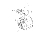
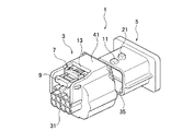
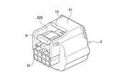
本実施の形態に係るコネクタ1は、互いに嵌合する一対のハウジング3,5と、一方のハウジングとしての雌ハウジング3に組付けられ組付方向への移動によって一対のハウジング3,5の嵌合状態を検知する検知部材7とを備えている。また、雌ハウジング3には撓み可能にロックバンド部9が設けられ、他方のハウジングとしての雄ハウジング5には一対のハウジング3,5が嵌合するときにロックバンド部9を撓ませてロックバンド部9が乗り越え可能となると共に一対のハウジング3,5の嵌合状態でロックバンド部9が係止されるロック部11が設けられ、検知部材7はロックバンド部9の上部に配置されロックバンド部9の撓みと共に配置位置が変動される。
The
そして、検知部材7には、ロックバンド部9がロック部11の上部に位置した状態で雌ハウジング3に設けられた当接規制部13と当接して組付方向への移動が規制される移動規制部15が設けられ、この移動規制部15は、ロックバンド部9がロック部11と係止した状態で当接規制部13との当接が解除されて検知部材7の組付方向への移動が可能となる。
Then, the
また、検知部材7には、一対のハウジング3,5が嵌合する前の状態で雌ハウジング3に設けられた仮当接規制部17と当接して組付方向への移動が規制される仮移動規制部19が設けられている。
Further, the
さらに、雄ハウジング5には、ロックバンド部9がロック部11と係止した状態で仮当接規制部17と仮移動規制部19との当接を解除させた状態で保持させる仮ロック解除部21が設けられている。
Further, the
また、検知部材7には、一対のハウジング3,5が嵌合する前の状態で雌ハウジング3に設けられた解除当接規制部23と当接して組付解除方向への移動が規制される解除移動規制部25が設けられている。
Further, the
さらに、検知部材7には、一対のハウジング3,5が嵌合し検知部材7が組付方向に移動した状態で雌ハウジング3に設けられた検知ロック部27に係止されて検知部材7の雌ハウジング3に対する組付状態が保持される保持ロック部29が設けられている。
Further, the
図1〜図8に示すように、雌ハウジング3は、筒状に形成され、内部に複数の端子収容室31が形成されている。複数の端子収容室31には、電線(不図示)などに電気的に接続された端子(不図示)が収容されている。また、雌ハウジング3の上部には、ロックバンド部9が撓み可能に設けられている。ロックバンド部9の先端には、下方に向けて係止突部33が突設されている。このロックバンド部9は、雄ハウジング5と嵌合する際に雄ハウジング5のロック部11と係止突部33とが係止することにより、雌ハウジング3と雄ハウジング5との嵌合状態が保持される。
As shown in FIGS. 1-8, the
雄ハウジング5は、雌ハウジング3よりも小径の筒状に形成され、内部に複数の端子収容室35が形成されている。複数の端子収容室35には、電線(不図示)などに電気的に接続され雌ハウジング3に収容された端子と電気的に接続される相手端子(不図示)が収容されている。また、雄ハウジング5の外周側の上部には、上方に向けてロック部11が突設されている。ロック部11は、雌ハウジング3との嵌合方向に向かって傾斜する傾斜面37が設けられている。このロック部11の嵌合方向後方には、ロック部11よりも突出高さが大きく形成された仮ロック解除部21が設けられ、ロック部11との間に係止凹部39を形成している。このロック部11は、雌ハウジング3と嵌合する際にロック部11の傾斜面37によって雌ハウジング3のロックバンド部9が上方に撓まされ、ロックバンド部9の係止突部33がロック部11を乗り越えることにより、係止突部33が係止凹部39内に係止され、ロック部11とロックバンド部9とが係止状態となる。
The
このように互いに嵌合する一対のハウジング3,5のうち雌ハウジング3には、ロックバンド部9の上方に空間部を形成するフード部41が設けられ、このフード部41内には、雌ハウジング3への組付方向の移動によって一対のハウジング3,5の嵌合状態を検知する検知部材7が組付けられる。
The
検知部材7は、ロックバンド部9の上部に配置されるようにフード部41内に組付けられ、ロックバンド部9の撓みと共に配置位置が変動される。この検知部材7は、移動規制部15と、仮移動規制部19と、解除移動規制部25と、保持ロック部29とを備えている。
The
移動規制部15は、検知部材7が雌ハウジング3に仮組されたときのロックバンド部9の上部に配置された状態で、雌ハウジング3に設けられた当接規制部13の下方に位置するように検知部材7に設けられている。この移動規制部15は、ロックバンド部9がロック部11の上部に位置することによって検知部材7の配置位置が上方に変動されることにより、当接規制部13に当接される。この当接により、ロックバンド部9とロック部11とが係止されていない状態、すなわち一対のハウジング3,5が半嵌合状態であるときには、検知部材7がフード部41内(組付方向)に向かって移動することができない。また、移動規制部15と当接規制部13との当接は、ロックバンド部9がロック部11と係止することによって検知部材7の配置位置が下方に変動されることにより、解除される。この当接解除により、ロックバンド部9がロック部11と係止した状態、すなわち一対のハウジング3,5が正規嵌合状態であるときには、検知部材7がフード部41内に向かって移動することができる。
The
仮移動規制部19は、基部からT字状に形成された部分の組付方向の先端面となっている。この仮移動規制部19は、検知部材7が雌ハウジング3に仮組された状態で、雌ハウジング3のフード部41内に突設されたサイドロック部43の検知部材7との対向面である仮当接規制部17と当接されている。この当接により、検知部材7が雌ハウジング3に仮組された状態では、検知部材7が組付方向に移動されることが防止されている。この仮移動規制部19と仮当接規制部17との当接は、ロックバンド部9とロック部11とが係止した状態で、検知部材7のT字状の解除移動規制部25が設けられた部分の下面45が雄ハウジング5の仮ロック解除部21の上部に乗り上げることによって解除状態が保持される。また、このとき、検知部材7のT字状の仮移動規制部19が設けられた部分の下面47も、サイドロック部43の上面49に乗り上がって解除状態が保持される。このため、一対のハウジング3,5が正規嵌合状態であるときには、検知部材7がフード部41内に向かって移動することができる。
The temporary
解除移動規制部25は、T字状に形成された部分の中央部の下方に設けられている。この解除移動規制部25は、検知部材7が雌ハウジング3に仮組された状態で、雌ハウジング3のロックバンド部9の基部側に設けられた解除当接規制部23と当接されている。この当接により、検知部材7が雌ハウジング3に仮組された状態では、検知部材7が組付解除方向に移動されることが防止されている。
The release
保持ロック部29は、T字状に形成された部分の仮移動規制部19が設けられた面の反対側の面となっている。この保持ロック部29は、一対のハウジング3,5が嵌合し検知部材7が組付方向に移動した状態で、サイドロック部43の仮当接規制部17が設けられた面の反対側の面である検知ロック部27に係止される。この係止により、検知部材7が雌ハウジング3に本組された状態(検知部材7がフード部41内に押し込まれた状態)では、検知部材7が組付解除方向に移動されることが防止され、検知部材7の本組状態が保持される。
The holding
なお、検知部材7には、作業者の指などを当接して検知部材7を組付方向に押圧移動させる操作部51が設けられている。例えば、一対のハウジング3,5が半嵌合状態である場合には当接規制部13と移動規制部15との当接により操作部51を押圧しても検知部材7が組付方向に移動することができず、一対のハウジング3,5が正規嵌合状態である場合には当接規制部13と移動規制部15との当接が解除されることにより操作部51を押圧することによって検知部材7を組付方向に移動させることができる。このように検知部材7に操作部51を設けることにより、一対のハウジング3,5の正規嵌合状態では検知部材7を組付方向に容易に押圧移動させることができる。
The
このように構成されたコネクタ1の一対のハウジング3,5の嵌合動作及び検知部材7の検知動作について説明する。
The fitting operation of the pair of
一対のハウジング3,5の嵌合前(もしくは嵌合開始)の状態では、仮移動規制部19と仮当接規制部17との当接及び解除移動規制部25と解除当接規制部23との当接によって、検知部材7の組付方向及び組付解除方向への移動が規制され、検知部材7の雌ハウジング3に対する仮組状態が保持されている。この状態では、検知部材7を雌ハウジング3に対して仮組したまま保持することができ、検知部材7と雌ハウジング3とを1つの部材として取り扱うことができる。
In a state before the pair of
一対のハウジング3,5の嵌合途中(もしくは半嵌合)の状態では、ロックバンド部9がロック部11によって上方に撓まされ、ロックバンド部9の上部に配置された検知部材7も配置位置が上方に変動される。この検知部材7の上方への移動により、移動規制部15と当接規制部13とが当接し、検知部材7のフード部41内への移動が規制される。このため、ロックバンド部9とロック部11とが係止していない状態、すなわち一対のハウジング3,5が半嵌合状態であるときには、検知部材7をフード部41内に移動させることができず、一対のハウジング3,5が正規嵌合に至っていないことを検知することができる。
When the pair of
一対のハウジング3,5が正規に嵌合した状態では、ロックバンド部9とロック部11とが係止状態となり、一対のハウジング3,5の嵌合状態が保持される。この状態では、ロックバンド部9が下方に復元し、ロックバンド部9の上部に配置された検知部材7も配置位置が下方に変動される。この検知部材7の下方への移動により、移動規制部15と当接規制部13との当接が解除される。また、このとき、検知部材7のT字状の部分の各下面45,47は、仮ロック解除部21の上部及びサイドロック部43の上面49に乗り上げられており、仮移動規制部19と仮当接規制部17との当接が解除された状態を保持されている。これらにより、検知部材7のフード部41内(組付方向)への移動規制が解除される。このため、ロックバンド部9とロック部11とが係止した状態、すなわち一対のハウジング3,5が正規嵌合状態であるときには、検知部材7をフード部41内に移動させることができ、一対のハウジング3,5が正規嵌合に至ったことを検知することができる。
In a state in which the pair of
一対のハウジング3,5が正規に嵌合した後では、検知部材7をフード部41内に移動させ、保持ロック部29を検知ロック部27に係止させる。この状態では、検知部材7が組付解除方向に移動されることが防止され、検知部材7の本組状態が保持される。
After the pair of
このようなコネクタ1では、検知部材7がロックバンド部9の上部に配置されロックバンド部9の撓みと共に配置位置が変動される。この検知部材7に設けられた移動規制部15は、ロックバンド部9がロック部11の上部に位置した状態で雌ハウジング3に設けられた当接規制部13と当接して検知部材7の組付方向への移動を規制し、ロックバンド部9がロック部11と係止した状態で当接規制部13との当接が解除されて検知部材7の組付方向への移動を可能としている。
In such a
このため、ロックバンド部9の撓みによって検知部材7が変形することがなく、検知部材7自体の配置位置の変動によって移動規制部15と当接規制部13とが当接、又は当接解除され、検知部材7の移動の規制、又は移動の規制解除が行われ、一対のハウジング3,5の嵌合状態を検知することができる。
For this reason, the
従って、検知部材7を複数回使用しても変形することがなく、検知部材7の耐久性を向上することができる。また、検知部材7が変形することがないので、検知部材7の変形を許容するスペースを設ける必要がなく、サイズの大型化を抑制することができる。さらには、一対のハウジング3,5の外径寸法を変更せずに検知部材7の作動スペースを確保することができ、既存のハウジングに対して大幅な設計変更を施す必要がない。
Therefore, even if the
また、検知部材7に一対のハウジング3,5が嵌合する前の状態で雌ハウジング3の仮当接規制部17と当接して組付方向への移動が規制される仮移動規制部19が設けられているので、一対のハウジング3,5の嵌合前に検知部材7が雌ハウジング3に対して組付けられることがなく、検知部材7の検知前の位置を確実に保持することができる。
Further, a temporary
さらに、雄ハウジング5にロックバンド部9がロック部11と係止した状態で仮当接規制部17と仮移動規制部19との当接を解除させた状態で保持させる仮ロック解除部21が設けられているので、ロックバンド部9がロック部11と係止した状態で検知部材7を組付方向に移動させることができ、検知部材7によって一対のハウジング3,5の正規嵌合状態を確実に検知することができる。
Furthermore, a temporary
また、検知部材7に一対のハウジング3,5が嵌合する前の状態で雌ハウジング3の解除当接規制部23と当接して組付解除方向への移動が規制される解除移動規制部25が設けられているので、一対のハウジング3,5の嵌合前に検知部材7が雌ハウジング3から離脱することを防止でき、検知部材7を雌ハウジング3に仮組した状態で雌ハウジング3と共に検知部材7を搬送することができる。
Further, the release
さらに、検知部材7に一対のハウジング3,5が嵌合し検知部材7が組付方向に移動した状態で雌ハウジング3の検知ロック部27に係止されて検知部材7の雌ハウジング3に対する組付状態が保持される保持ロック部29が設けられているので、一対のハウジング3,5の嵌合した後の状態で検知部材7を雌ハウジング3に対して確実に保持させることができる。
Further, the pair of
(第2実施形態)
図9〜図16を用いて第2実施形態について説明する。
(Second Embodiment)
A second embodiment will be described with reference to FIGS.
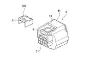
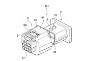
本実施の形態に係るコネクタ101は、検知部材103には、ロックバンド部9がロック部11の上部に位置した状態で雌ハウジング3に設けられた当接規制部13と当接して組付方向への移動が規制される移動規制部105が設けられ、この移動規制部105は、ロックバンド部9がロック部11と係止した状態で当接規制部13との当接が解除されて検知部材103の組付方向への移動が可能となる。
In the
また、検知部材103には、一対のハウジング3,5が嵌合する前の状態で雌ハウジング3に設けられた仮当接規制部としての当接規制部13と当接して組付方向への移動が規制される仮移動規制部107が設けられている。
Further, the
さらに、検知部材103には、一対のハウジング3,5が嵌合する前の状態で雌ハウジング3に設けられた解除当接規制部109と当接して組付解除方向への移動が規制される解除移動規制部111が設けられている。
Furthermore, the
また、検知部材103には、一対のハウジング3,5が嵌合し検知部材103が組付方向に移動した状態で雌ハウジング3に設けられた検知ロック部113に係止されて検知部材103の雌ハウジング3に対する組付状態が保持される保持ロック部115が設けられている。なお、第1実施形態と同一の構成には、同一の記号を記して説明を省略するが、第1実施形態と同一の構成であるので、構成及び機能説明は第1実施形態を参照するものとし省略するが、得られる効果は同一である。
The
図9〜図16に示すように、検知部材103は、ロックバンド部9の上部に配置されるようにフード部41内に組付けられ、ロックバンド部9の撓みと共に配置位置が変動される。この検知部材103は、移動規制部105と、仮移動規制部107と、解除移動規制部111と、保持ロック部115とを備えている。
As shown in FIGS. 9 to 16, the
移動規制部105は、検知部材103の組付方向先端側の2つの爪状に形成された部分の下方に設けられた傾斜面となっている。この爪状に形成された部分は、検知部材103が雌ハウジング3に仮組されたときのロックバンド部9の上部に配置された状態で、雌ハウジング3の当接規制部13の下方に位置されている。この移動規制部105は、ロックバンド部9がロック部11の上部に位置することによって検知部材103の配置位置が上方に変動されることにより、当接規制部13に当接される。この当接により、ロックバンド部9とロック部11とが係止されていない状態、すなわち一対のハウジング3,5が半嵌合状態であるときには、検知部材103がフード部41内に向かって移動することができない。また、移動規制部105と当接規制部13との当接は、ロックバンド部9がロック部11と係止することによって検知部材103の配置位置が下方に変動されることにより、解除される。この当接解除により、ロックバンド部9がロック部11と係止した状態、すなわち一対のハウジング3,5が正規嵌合状態であるときには、検知部材103がフード部41内に向かって移動することができる。
The
仮移動規制部107は、爪状に形成された部分の上方に設けられた傾斜面となっている。この仮移動規制部107は、検知部材103が雌ハウジング3に仮組された状態で、当接規制部13と当接されている。なお、当接規制部13に仮移動規制部107と同様の傾斜面を設けて仮当接規制部としてもよい。この当接により、検知部材103が雌ハウジング3に仮組された状態では、不意な外力などによって検知部材103が組付方向に移動されることが防止されている。この仮移動規制部107と当接規制部13との当接は、仮移動規制部107の傾斜がロックバンド部9がロック部11の上部に位置する程度の力で解除可能に設定されており、ロックバンド部9がロック部11の上部に位置したとき、もしくは検知部材103をフード部41内へ押し込むことによって解除される。このため、移動規制部105と当接規制部13との当接を妨げることがないと共に、一対のハウジング3,5が正規嵌合状態であるときには、検知部材103をフード部41内に向かって移動させることができる。
The temporary
解除移動規制部111は、検知部材の下方に設けられた傾斜面となっている。この解除移動規制部111は、検知部材103が雌ハウジング3に仮組された状態で、雌ハウジング3に解除移動規制部111と同様の傾斜面で設けられた解除当接規制部109と当接されている。この当接により、検知部材103が雌ハウジング3に仮組された状態では、不意な外力などによって検知部材103が組付解除方向に移動されることが防止されている。
The release
保持ロック部115は、爪状に形成された部分の仮移動規制部107が設けられた面の反対側の面となっている。この保持ロック部115は、一対のハウジング3,5が嵌合し検知部材103が組付方向に移動した状態で、フード部41内に突設された検知ロック部113に係止される。この係止により、検知部材103が雌ハウジング3に本組された状態では、検知部材103が組付解除方向に移動されることが防止され、検知部材103の本組状態が保持される。
The holding
このように構成されたコネクタ101の一対のハウジング3,5の嵌合動作及び検知部材103の検知動作について説明する。
The fitting operation of the pair of
一対のハウジング3,5の嵌合前(もしくは嵌合開始)の状態では、仮移動規制部107と当接規制部13との当接及び解除移動規制部111と解除当接規制部109との当接によって、検知部材103の組付方向及び組付解除方向への移動が規制され、検知部材103の雌ハウジング3に対する仮組状態が保持されている。この状態では、当接解除を目的とした外力以外の不意な外力によって当接が解除されることがなく、検知部材103を雌ハウジング3に対して仮組したまま保持することができ、検知部材103と雌ハウジング3とを1つの部材として取り扱うことができる。
In a state before the pair of
一対のハウジング3,5の嵌合途中(もしくは半嵌合)の状態では、ロックバンド部9がロック部11によって上方に撓まされ、ロックバンド部9の上部に配置された検知部材103も配置位置が上方に変動される。この検知部材103の上方への移動により、仮移動規制部107と当接規制部13との当接が解除され、移動規制部105と当接規制部13とが当接し、検知部材103のフード部41内(組付方向)への移動が規制される。このため、ロックバンド部9とロック部11とが係止していない状態、すなわち一対のハウジング3,5が半嵌合状態であるときには、検知部材103をフード部41内に移動させることができず、一対のハウジング3,5が正規嵌合に至っていないことを検知することができる。
In a state in which the pair of
一対のハウジング3,5が正規に嵌合した状態では、ロックバンド部9とロック部11とが係止状態となり、一対のハウジング3,5の嵌合状態が保持される。この状態では、ロックバンド部9が下方に復元し、ロックバンド部9の上部に配置された検知部材103も配置位置が下方に変動される。この検知部材103の下方への移動により、移動規制部105と当接規制部13との当接が解除される。なお、移動規制部105は傾斜面となっているため、ロックバンド部9の下方への復元(検知部材103の配置位置の下方への移動)によって当接規制部13との当接を解除することができる。このため、ロックバンド部9とロック部11とが係止した状態、すなわち一対のハウジング3,5が正規嵌合状態であるときには、検知部材103をフード部41内に押し込んで移動させることができ、一対のハウジング3,5が正規嵌合に至ったことを検知することができる。
In a state in which the pair of
一対のハウジング3,5が正規に嵌合した後では、検知部材103をフード部41内に押し込んで移動させ、保持ロック部115を検知ロック部113に係止させる。この状態では、検知部材103が組付解除方向に移動されることが防止され、検知部材103の本組状態が保持される。
After the pair of
このようなコネクタ101では、検知部材103がロックバンド部9の上部に配置されロックバンド部9の撓みと共に配置位置が変動される。この検知部材103に設けられた移動規制部105は、ロックバンド部9がロック部11の上部に位置した状態で雌ハウジング3に設けられた当接規制部13と当接して検知部材103の組付方向への移動を規制し、ロックバンド部9がロック部11と係止した状態で当接規制部13との当接が解除されて検知部材103の組付方向への移動を可能としている。
In such a
このため、ロックバンド部9の撓みによって検知部材103が変形することがなく、検知部材103自体の配置位置の変動によって移動規制部105と当接規制部13とが当接、又は当接解除され、検知部材103の移動の規制、又は移動の規制解除が行われ、一対のハウジング3,5の嵌合状態を検知することができる。
For this reason, the
従って、検知部材103を複数回使用しても変形することがなく、検知部材103の耐久性を向上することができる。また、検知部材103が変形することがないので、検知部材103の変形を許容するスペースを設ける必要がなく、サイズの大型化を抑制することができる。さらには、一対のハウジング3,5の外径寸法を変更せずに検知部材103の作動スペースを確保することができ、既存のハウジングに対して大幅な設計変更を施す必要がない。
Therefore, even if the
また、検知部材103に一対のハウジング3,5が嵌合する前の状態で雌ハウジング3の当接規制部13と当接して組付方向への移動が規制される仮移動規制部107が設けられているので、一対のハウジング3,5の嵌合前に検知部材103が雌ハウジング3に対して組付けられることがなく、検知部材103の検知前の位置を確実に保持することができる。
In addition, a provisional
さらに、検知部材103に一対のハウジング3,5が嵌合する前の状態で雌ハウジング3の解除当接規制部109と当接して組付解除方向への移動が規制される解除移動規制部111が設けられているので、一対のハウジング3,5の嵌合前に検知部材103が雌ハウジング3から離脱することを防止でき、検知部材103を雌ハウジング3に仮組した状態で雌ハウジング3と共に検知部材103を搬送することができる。
Further, the release
また、検知部材103に一対のハウジング3,5が嵌合し検知部材103が組付方向に移動した状態で雌ハウジング3の検知ロック部113に係止されて検知部材103の雌ハウジング3に対する組付状態が保持される保持ロック部115が設けられているので、一対のハウジング3,5の嵌合した後の状態で検知部材103を雌ハウジング3に対して確実に保持させることができる。
In addition, the pair of
(第3実施形態)
図17〜図20を用いて第3実施形態について説明する。
(Third embodiment)
A third embodiment will be described with reference to FIGS.
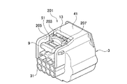
本実施の形態に係るコネクタ201は、検知部材203には、一対のハウジング3,5が嵌合する前の状態で雌ハウジング3に設けられたガタ当接規制部205と当接して組付方向と交差する方向への移動が規制されるガタ規制部207が設けられている。なお、第1実施形態と同一の構成には、同一の記号を記して説明を省略するが、第1実施形態と同一の構成であるので、構成及び機能説明は第1実施形態を参照するものとし省略するが、得られる効果は同一である。
The
図17〜図20に示すように、ガタ規制部207は、検知部材203の両側部に複数(ここでは3つ)設けられた突部の上面となっている。このガタ規制部207は、検知部材203が雌ハウジング3に仮組された状態で、雌ハウジング3のフード部41の側面となるガタ当接規制部205と当接されている。この当接により、検知部材203が雌ハウジング3に仮組された状態では、組付方向と交差する方向(検知部材203の側部方向)への移動、すなわち検知部材203の雌ハウジング3に対するガタつきが規制され、検知部材203の仮組状態を安定して保持することができる。
As shown in FIGS. 17 to 20, the
なお、ガタ規制部207は、側部の片側に複数設けられているが、検知部材203のガタつきを規制できるものであれば、1つであってもよく、さらに検知部材203のガタつきを規制するのであれば、さらに複数設けてもよい。また、本実施の形態に係るコネクタ201では、検知部材203の形状が第1実施形態と同様であるが、第2実施形態の形状の検知部材103にもガタ規制部207を設けることができる。また、ガタ規制部207及びガタ当接規制部205は、検知部材の雌ハウジング3に対するガタつきを規制できるものであれば、どのような形状であってもよい。
In addition, although the
このようなコネクタ201では、検知部材203に一対のハウジング3,5が嵌合する前の状態で雌ハウジング3に設けられたガタ当接規制部205と当接して組付方向と交差する方向への移動が規制されるガタ規制部207が設けられているので、一対のハウジング3,5の嵌合前に検知部材203が雌ハウジング3に対してガタつくことがなく、検知部材203を雌ハウジング3に仮組した状態を安定して保持することができる。
In such a
なお、本発明の実施の形態に係るコネクタでは、2種類の形状の検知部材を示しているが、これに限定されるものではなく、検知部材自体の位置が変動し、移動規制部などの各部分が検知部材の周辺に配置される周辺部材に対して影響を与えるような変形をするものでなければ、検知部材の形状はどのような形態であってもよい。 In the connector according to the embodiment of the present invention, two types of shapes of detection members are shown. However, the present invention is not limited to this, and the position of the detection member itself fluctuates. The shape of the detection member may be any shape as long as the portion does not deform so as to affect the peripheral member arranged around the detection member.
1,101,201…コネクタ
3,5…一対のハウジング
7,103,203…検知部材
9…ロックバンド部
11…ロック部
13…当接規制部
15,105…移動規制部
17…仮当接規制部
19,107…仮移動規制部
21…仮ロック解除部
23,109…解除当接規制部
25,111…解除移動規制部
27,113…検知ロック部
29,115…保持ロック部
205…ガタ当接規制部
207…ガタ規制部
DESCRIPTION OF SYMBOLS 1,101,201 ...
Claims (6)
前記一方のハウジングには撓み可能にロックバンド部が設けられ、他方のハウジングには前記一対のハウジングが嵌合するときに前記ロックバンド部を撓ませて前記ロックバンド部が乗り越え可能となると共に前記一対のハウジングの嵌合状態で前記ロックバンド部が係止されるロック部が設けられ、前記検知部材は前記ロックバンド部の上部に配置され前記ロックバンド部の撓みと共に配置位置が変動され、
前記検知部材には、前記ロックバンド部が前記ロック部の上部に位置した状態で前記一方のハウジングに設けられた当接規制部と当接して組付方向への移動が規制される移動規制部が設けられ、この移動規制部は、前記ロックバンド部が前記ロック部と係止した状態で前記当接規制部との当接が解除されて前記検知部材の組付方向への移動が可能となることを特徴とするコネクタ。 A connector provided with a pair of housings that fit together, and a detection member that is assembled to one of the pair of housings and detects a fitting state of the pair of housings by movement in the assembly direction. There,
The one housing is provided with a bendable lock band portion, and the other housing is bent when the pair of housings are fitted so that the lock band portion can be overcome and the lock band portion can be overcome. A lock portion is provided in which the lock band portion is locked in a fitted state of a pair of housings, and the detection member is arranged at an upper portion of the lock band portion, and the arrangement position is changed with bending of the lock band portion,
The detection member includes a movement restricting portion in which movement in the assembling direction is restricted by contacting a contact restricting portion provided on the one housing in a state where the lock band portion is positioned on the upper portion of the lock portion. The movement restricting portion can be moved in the assembling direction of the detection member by releasing the contact with the contact restricting portion in a state where the lock band portion is engaged with the lock portion. The connector characterized by becoming.
前記検知部材には、前記一対のハウジングが嵌合する前の状態で前記一方のハウジングに設けられたガタ当接規制部と当接して組付方向と交差する方向への移動が規制されるガタ規制部が設けられていることを特徴とするコネクタ。 The connector according to claim 1,
The detection member is in contact with a backlash contact restricting portion provided on the one housing in a state before the pair of housings are fitted to each other, and the backlash is restricted from moving in a direction crossing the assembly direction. A connector characterized in that a restricting portion is provided.
前記検知部材には、前記一対のハウジングが嵌合する前の状態で前記一方のハウジングに設けられた仮当接規制部と当接して組付方向への移動が規制される仮移動規制部が設けられていることを特徴とするコネクタ。 The connector according to claim 1 or 2,
The detection member has a temporary movement restricting portion that is in contact with a temporary contact restricting portion provided on the one housing before the pair of housings are fitted to restrict movement in the assembly direction. A connector characterized by being provided.
前記他方のハウジングには、前記ロックバンド部が前記ロック部と係止した状態で前記仮当接規制部と前記仮移動規制部との当接を解除させた状態で保持させる仮ロック解除部が設けられていることを特徴とするコネクタ。 The connector according to claim 3, wherein
The other housing includes a temporary lock release portion that holds the lock band portion in a state where the lock contact portion is engaged with the lock portion and the contact between the temporary contact restriction portion and the temporary movement restriction portion is released. A connector characterized by being provided.
前記検知部材には、前記一対のハウジングが嵌合する前の状態で前記一方のハウジングに設けられた解除当接規制部と当接して組付解除方向への移動が規制される解除移動規制部が設けられていることを特徴とするコネクタ。 The connector according to any one of claims 1 to 4,
The detection member is a release movement restricting portion that is in contact with a release contact restricting portion provided in the one housing before the pair of housings are fitted together and is restricted from moving in the assembly releasing direction. The connector characterized by being provided.
前記検知部材には、前記一対のハウジングが嵌合し前記検知部材が組付方向に移動した状態で前記一方のハウジングに設けられた検知ロック部に係止されて前記検知部材の前記一方のハウジングに対する組付状態が保持される保持ロック部が設けられていることを特徴とするコネクタ。 The connector according to any one of claims 1 to 5,
The detection member is engaged with the detection lock portion provided in the one housing in a state where the pair of housings are fitted and the detection member is moved in the assembly direction. A connector having a holding lock portion for holding an assembled state with respect to the connector.
Priority Applications (2)
| Application Number | Priority Date | Filing Date | Title |
|---|---|---|---|
| JP2009162470A JP5486859B2 (en) | 2009-07-09 | 2009-07-09 | connector |
| US12/784,600 US7980887B2 (en) | 2009-07-09 | 2010-05-21 | Connector |
Applications Claiming Priority (1)
| Application Number | Priority Date | Filing Date | Title |
|---|---|---|---|
| JP2009162470A JP5486859B2 (en) | 2009-07-09 | 2009-07-09 | connector |
Publications (2)
| Publication Number | Publication Date |
|---|---|
| JP2011018564A true JP2011018564A (en) | 2011-01-27 |
| JP5486859B2 JP5486859B2 (en) | 2014-05-07 |
Family
ID=43427814
Family Applications (1)
| Application Number | Title | Priority Date | Filing Date |
|---|---|---|---|
| JP2009162470A Active JP5486859B2 (en) | 2009-07-09 | 2009-07-09 | connector |
Country Status (2)
| Country | Link |
|---|---|
| US (1) | US7980887B2 (en) |
| JP (1) | JP5486859B2 (en) |
Cited By (1)
| Publication number | Priority date | Publication date | Assignee | Title |
|---|---|---|---|---|
| JP2018014243A (en) * | 2016-07-21 | 2018-01-25 | 矢崎総業株式会社 | connector |
Families Citing this family (14)
| Publication number | Priority date | Publication date | Assignee | Title |
|---|---|---|---|---|
| JP5764023B2 (en) * | 2011-09-27 | 2015-08-12 | 矢崎総業株式会社 | connector |
| US8628344B2 (en) * | 2011-10-12 | 2014-01-14 | Yazaki North America, Inc. | Connector and terminal positioning mechanism |
| JP5751196B2 (en) * | 2012-03-09 | 2015-07-22 | 住友電装株式会社 | connector |
| US8920187B2 (en) * | 2012-03-09 | 2014-12-30 | Sumitomo Wiring Systems, Ltd. | Connector and connector assembly |
| US8926355B2 (en) * | 2012-06-29 | 2015-01-06 | Lear Corporation | Connector position assurance device for a connector assembly |
| JP6143578B2 (en) * | 2013-06-26 | 2017-06-07 | 矢崎総業株式会社 | Electrical component equipment |
| JP2015079710A (en) | 2013-10-18 | 2015-04-23 | 住友電装株式会社 | Connector |
| JP6150172B2 (en) * | 2014-02-28 | 2017-06-21 | 住友電装株式会社 | connector |
| JP6560273B2 (en) * | 2017-02-06 | 2019-08-14 | 矢崎総業株式会社 | Mating connector |
| WO2019045038A1 (en) * | 2017-08-31 | 2019-03-07 | 矢崎総業株式会社 | Connector and connector unit |
| CN207320479U (en) * | 2017-10-17 | 2018-05-04 | 安费诺精密连接器(深圳)有限公司 | A kind of high-tension connector |
| WO2019131264A1 (en) * | 2017-12-26 | 2019-07-04 | 住友電装株式会社 | Connector |
| US10355414B1 (en) | 2018-02-08 | 2019-07-16 | Delphi Technologies, Llc | Connector with a connector position assurance device |
| JP7365931B2 (en) * | 2020-02-19 | 2023-10-20 | 住友電工オプティフロンティア株式会社 | optical connector |
Citations (3)
| Publication number | Priority date | Publication date | Assignee | Title |
|---|---|---|---|---|
| JP2004063090A (en) * | 2002-07-24 | 2004-02-26 | Sumitomo Wiring Syst Ltd | Fitting detecting connector |
| JP2008210530A (en) * | 2007-02-23 | 2008-09-11 | Sumitomo Wiring Syst Ltd | Connector |
| JP2009004318A (en) * | 2007-06-25 | 2009-01-08 | Sumitomo Wiring Syst Ltd | Connector |
Family Cites Families (11)
| Publication number | Priority date | Publication date | Assignee | Title |
|---|---|---|---|---|
| JP3496803B2 (en) * | 1997-12-04 | 2004-02-16 | 矢崎総業株式会社 | Connector mating detection mechanism |
| JP3841389B2 (en) * | 2000-02-25 | 2006-11-01 | 矢崎総業株式会社 | Connector mating structure |
| JP3887142B2 (en) * | 2000-05-18 | 2007-02-28 | 矢崎総業株式会社 | Half mating detection connector |
| JP3920055B2 (en) * | 2001-04-12 | 2007-05-30 | 矢崎総業株式会社 | Method of assembling half-fitting prevention connector and half-fitting prevention connector |
| JP3555591B2 (en) * | 2001-04-26 | 2004-08-18 | 住友電装株式会社 | connector |
| JP3813836B2 (en) * | 2001-05-18 | 2006-08-23 | 矢崎総業株式会社 | Half-mating prevention connector |
| JP3810285B2 (en) * | 2001-06-12 | 2006-08-16 | 矢崎総業株式会社 | Half-mating prevention connector |
| JP3976134B2 (en) * | 2001-09-05 | 2007-09-12 | 矢崎総業株式会社 | Half-mating prevention connector |
| JP2003142209A (en) * | 2001-11-07 | 2003-05-16 | Sumitomo Wiring Syst Ltd | Connector |
| JP3901053B2 (en) | 2002-08-05 | 2007-04-04 | 住友電装株式会社 | connector |
| JP5119909B2 (en) * | 2007-12-26 | 2013-01-16 | 住友電装株式会社 | connector |
-
2009
- 2009-07-09 JP JP2009162470A patent/JP5486859B2/en active Active
-
2010
- 2010-05-21 US US12/784,600 patent/US7980887B2/en active Active
Patent Citations (3)
| Publication number | Priority date | Publication date | Assignee | Title |
|---|---|---|---|---|
| JP2004063090A (en) * | 2002-07-24 | 2004-02-26 | Sumitomo Wiring Syst Ltd | Fitting detecting connector |
| JP2008210530A (en) * | 2007-02-23 | 2008-09-11 | Sumitomo Wiring Syst Ltd | Connector |
| JP2009004318A (en) * | 2007-06-25 | 2009-01-08 | Sumitomo Wiring Syst Ltd | Connector |
Cited By (1)
| Publication number | Priority date | Publication date | Assignee | Title |
|---|---|---|---|---|
| JP2018014243A (en) * | 2016-07-21 | 2018-01-25 | 矢崎総業株式会社 | connector |
Also Published As
| Publication number | Publication date |
|---|---|
| US20110008988A1 (en) | 2011-01-13 |
| JP5486859B2 (en) | 2014-05-07 |
| US7980887B2 (en) | 2011-07-19 |
Similar Documents
| Publication | Publication Date | Title |
|---|---|---|
| JP5486859B2 (en) | connector | |
| EP2866309B1 (en) | Connector structure | |
| US20130252455A1 (en) | Connector assembly | |
| JP2006339154A (en) | Connector having lock lever | |
| JP6335805B2 (en) | Connector lock structure | |
| CN109713518B (en) | Electric connector with position assurance device | |
| JP6138428B2 (en) | connector | |
| JP2011134656A (en) | Lock cover of electrical connection device | |
| JP2011034831A (en) | Connector | |
| JP2011029016A (en) | Connector | |
| JP2021026929A5 (en) | ||
| KR101676884B1 (en) | Connector | |
| CN111193142B (en) | Connector with a locking member | |
| JP5626118B2 (en) | connector | |
| JP2015185311A (en) | connector assembly and connector | |
| EP2751880B1 (en) | Waterproof connector | |
| JP2001068216A (en) | Lock mechanism of connector | |
| JP5739695B2 (en) | Connector device | |
| JP2008140731A (en) | Connector | |
| JP7181155B2 (en) | Connectors and wire harnesses | |
| JP4242378B2 (en) | Electrical connector with locking mechanism | |
| JP2019029080A (en) | Fitting detection connector device and female connector | |
| JP7096128B2 (en) | connector | |
| JP2010225391A (en) | Connector | |
| JP2010073364A (en) | Connector |
Legal Events
| Date | Code | Title | Description |
|---|---|---|---|
| A621 | Written request for application examination |
Free format text: JAPANESE INTERMEDIATE CODE: A621 Effective date: 20120531 |
|
| A977 | Report on retrieval |
Free format text: JAPANESE INTERMEDIATE CODE: A971007 Effective date: 20130530 |
|
| A131 | Notification of reasons for refusal |
Free format text: JAPANESE INTERMEDIATE CODE: A131 Effective date: 20130611 |
|
| TRDD | Decision of grant or rejection written | ||
| A01 | Written decision to grant a patent or to grant a registration (utility model) |
Free format text: JAPANESE INTERMEDIATE CODE: A01 Effective date: 20140212 |
|
| A61 | First payment of annual fees (during grant procedure) |
Free format text: JAPANESE INTERMEDIATE CODE: A61 Effective date: 20140224 |
|
| R150 | Certificate of patent or registration of utility model |
Ref document number: 5486859 Country of ref document: JP Free format text: JAPANESE INTERMEDIATE CODE: R150 |
|
| R250 | Receipt of annual fees |
Free format text: JAPANESE INTERMEDIATE CODE: R250 |
|
| R250 | Receipt of annual fees |
Free format text: JAPANESE INTERMEDIATE CODE: R250 |
|
| R250 | Receipt of annual fees |
Free format text: JAPANESE INTERMEDIATE CODE: R250 |
|
| R250 | Receipt of annual fees |
Free format text: JAPANESE INTERMEDIATE CODE: R250 |
|
| R250 | Receipt of annual fees |
Free format text: JAPANESE INTERMEDIATE CODE: R250 |
|
| R250 | Receipt of annual fees |
Free format text: JAPANESE INTERMEDIATE CODE: R250 |
|
| R250 | Receipt of annual fees |
Free format text: JAPANESE INTERMEDIATE CODE: R250 |
|
| S531 | Written request for registration of change of domicile |
Free format text: JAPANESE INTERMEDIATE CODE: R313531 |
|
| R350 | Written notification of registration of transfer |
Free format text: JAPANESE INTERMEDIATE CODE: R350 |
|
| R250 | Receipt of annual fees |
Free format text: JAPANESE INTERMEDIATE CODE: R250 |
