JP2011007912A - Illumination apparatus and projection display apparatus - Google Patents
Illumination apparatus and projection display apparatus Download PDFInfo
- Publication number
- JP2011007912A JP2011007912A JP2009149652A JP2009149652A JP2011007912A JP 2011007912 A JP2011007912 A JP 2011007912A JP 2009149652 A JP2009149652 A JP 2009149652A JP 2009149652 A JP2009149652 A JP 2009149652A JP 2011007912 A JP2011007912 A JP 2011007912A
- Authority
- JP
- Japan
- Prior art keywords
- light
- component light
- component
- light source
- polarization
- Prior art date
- Legal status (The legal status is an assumption and is not a legal conclusion. Google has not performed a legal analysis and makes no representation as to the accuracy of the status listed.)
- Pending
Links
Images


Classifications
-
- G—PHYSICS
- G03—PHOTOGRAPHY; CINEMATOGRAPHY; ANALOGOUS TECHNIQUES USING WAVES OTHER THAN OPTICAL WAVES; ELECTROGRAPHY; HOLOGRAPHY
- G03B—APPARATUS OR ARRANGEMENTS FOR TAKING PHOTOGRAPHS OR FOR PROJECTING OR VIEWING THEM; APPARATUS OR ARRANGEMENTS EMPLOYING ANALOGOUS TECHNIQUES USING WAVES OTHER THAN OPTICAL WAVES; ACCESSORIES THEREFOR
- G03B21/00—Projectors or projection-type viewers; Accessories therefor
- G03B21/14—Details
- G03B21/20—Lamp housings
- G03B21/2073—Polarisers in the lamp house
-
- H—ELECTRICITY
- H04—ELECTRIC COMMUNICATION TECHNIQUE
- H04N—PICTORIAL COMMUNICATION, e.g. TELEVISION
- H04N9/00—Details of colour television systems
- H04N9/12—Picture reproducers
- H04N9/31—Projection devices for colour picture display, e.g. using electronic spatial light modulators [ESLM]
- H04N9/3102—Projection devices for colour picture display, e.g. using electronic spatial light modulators [ESLM] using two-dimensional electronic spatial light modulators
- H04N9/3111—Projection devices for colour picture display, e.g. using electronic spatial light modulators [ESLM] using two-dimensional electronic spatial light modulators for displaying the colours sequentially, e.g. by using sequentially activated light sources
- H04N9/3114—Projection devices for colour picture display, e.g. using electronic spatial light modulators [ESLM] using two-dimensional electronic spatial light modulators for displaying the colours sequentially, e.g. by using sequentially activated light sources by using a sequential colour filter producing one colour at a time
Abstract
Description
本発明は、光源と、光源から出射される光を変調する反射型光変調素子とを備える照明装置及び投写型映像表示装置に関する。 The present invention relates to an illumination apparatus and a projection display apparatus including a light source and a reflective light modulation element that modulates light emitted from the light source.
従来、光源と、光源から出射された光を変調する光変調素子と、光変調素子から出射された光を投写面上に投写する投写ユニットとを有する投写型映像表示装置が知られている。 2. Description of the Related Art Conventionally, there is known a projection display apparatus including a light source, a light modulation element that modulates light emitted from the light source, and a projection unit that projects light emitted from the light modulation element onto a projection surface.
また、DMD(Digital Micromirror Device)などの反射型光変調素子を用いた投写型映像表示装置も知られている。このような投写型映像表示装置には、光源から出射された光を均一化する均一化部、均一化部によって均一化された光を分離する色分離部などが設けられる。均一化部としては、例えば、ロッドインテグレータやフライアイレンズなどが用いられる。色分離部としては、例えば、カラーホイールや色分離合成プリズムが用いられる。 A projection display apparatus using a reflective light modulation element such as a DMD (Digital Micromirror Device) is also known. Such a projection display apparatus is provided with a homogenizing unit that uniformizes light emitted from the light source, a color separation unit that separates the light homogenized by the homogenizing unit, and the like. For example, a rod integrator or a fly-eye lens is used as the uniformizing unit. For example, a color wheel or a color separation / combination prism is used as the color separation unit.
ここで、DMDなどの反射型光変調素子を用いた投写型映像表示装置において、不要光の除去によって、映像を構成する色成分光(例えば、赤成分光、緑成分光、青成分光)の純度を高める技術も提案されている(例えば、特許文献1)。 Here, in a projection display apparatus using a reflective light modulation element such as DMD, by removing unnecessary light, color component light (for example, red component light, green component light, blue component light) constituting an image is removed. A technique for increasing the purity has also been proposed (for example, Patent Document 1).
上述した投写型映像表示装置では、映像を構成する色成分光(例えば、赤成分光、緑成分光、青成分光)の純度を高めるために不要光が除去される。従って、反射型光変調素子に導かれる総光量が低下してしまう。 In the projection display apparatus described above, unnecessary light is removed in order to increase the purity of color component light (for example, red component light, green component light, and blue component light) that constitutes an image. Accordingly, the total amount of light guided to the reflective light modulation element is reduced.
そこで、本発明は、上述した課題を解決するためになされたものであり、反射型光変調素子に導かれる総光量の低下を抑制しながら、投写面に投写される映像の色再現範囲を切り替えることを可能とする照明装置及び投写型映像表示装置を提供することを目的とする。 Therefore, the present invention has been made to solve the above-described problems, and switches the color reproduction range of an image projected on the projection surface while suppressing a decrease in the total light amount guided to the reflective light modulation element. It is an object of the present invention to provide an illumination device and a projection display device that enable this.
第1の特徴に係る照明装置は、光源(光源10)と、前記光源から出射される光を変調する反射型光変調素子(DMD200)とを備える。照明装置は、前記光源から出射される光の偏光方向を単一の偏光方向に揃える偏光変換素子(偏光変換素子31)と、前記偏光変換素子によって前記単一の偏光方向に揃えられた光を分離する色分離部(プリズム70及びプリズム80、又は、カラーホイール140)と、前記光源から出射される光の波長帯のうち、所定波長帯の光の偏光状態を調整する狭帯域偏光状態調整素子(狭帯域偏光状態調整素子32)とを備える。前記狭帯域偏光状態調整素子は、前記光源から出射される光の光路上において、前記偏光変換素子と前記色分離部との間に設けられる。
The illumination device according to the first feature includes a light source (light source 10) and a reflective light modulation element (DMD 200) that modulates light emitted from the light source. The illumination device includes a polarization conversion element (polarization conversion element 31) that aligns the polarization direction of light emitted from the light source to a single polarization direction, and light that is aligned in the single polarization direction by the polarization conversion element. A color separation unit (the
第1の特徴において、前記色分離部は、少なくともダイクロイック面を有する。前記所定波長帯は、前記ダイクロイック面のカットオフ波長を含む。 In the first feature, the color separation unit has at least a dichroic surface. The predetermined wavelength band includes a cutoff wavelength of the dichroic surface.
第1の特徴において、前記色分離部は、回転可能に構成されており、円盤形状の盤面を有するカラーホイール(カラーホイール140)である。前記カラーホイールに設けられた前記盤面の法線は、前記光源から出射された光の光軸に対して傾いている。 In the first feature, the color separation unit is a color wheel (color wheel 140) configured to be rotatable and having a disk-shaped board surface. The normal of the board surface provided in the color wheel is inclined with respect to the optical axis of the light emitted from the light source.
第1の特徴において、前記所定波長帯は、青成分光の波長帯と緑成分光の波長帯、又は、緑成分光の波長帯と赤成分光の波長帯との間の波長帯を含む。 In the first feature, the predetermined wavelength band includes a wavelength band of blue component light and a wavelength band of green component light, or a wavelength band between a wavelength band of green component light and a wavelength band of red component light.
第2の特徴に係る投写型映像表示装置は、光源と、前記光源から出射される光を変調する反射型光変調素子と、前記反射型光変調素子から出射された光を投写面上に投写する投写ユニットとを備える。投写型映像表示装置は、前記光源から出射される光の偏光方向を単一の偏光方向に揃える偏光変換素子と、前記偏光変換素子によって前記単一の偏光方向に揃えられた光を分離する色分離部と、前記光源から出射される光の波長帯のうち、所定波長帯の光の偏光状態を調整する狭帯域偏光状態調整素子とを備える。前記狭帯域偏光状態調整素子は、前記光源から出射される光の光路上において、前記偏光変換素子と前記色分離部との間に設けられる。 A projection display apparatus according to a second feature projects a light source, a reflection type light modulation element that modulates light emitted from the light source, and light emitted from the reflection type light modulation element onto a projection surface. A projection unit. The projection display apparatus includes: a polarization conversion element that aligns the polarization direction of light emitted from the light source to a single polarization direction; and a color that separates the light aligned in the single polarization direction by the polarization conversion element. A separation unit; and a narrow-band polarization state adjusting element that adjusts a polarization state of light in a predetermined wavelength band among light wavelength bands emitted from the light source. The narrow-band polarization state adjusting element is provided between the polarization conversion element and the color separation unit on an optical path of light emitted from the light source.
本発明によれば、反射型光変調素子に導かれる総光量の低下を抑制しながら、投写面に投写される映像の色再現範囲を切り替えることを可能とする照明装置及び投写型映像表示装置を提供することができる。 According to the present invention, there is provided an illuminating device and a projection image display device capable of switching a color reproduction range of an image projected on a projection surface while suppressing a decrease in the total light amount guided to the reflective light modulation element. Can be provided.
以下において、本発明の実施形態に係る照明装置及び投写型映像表示装置について、図面を参照しながら説明する。なお、以下の図面の記載において、同一又は類似の部分には、同一又は類似の符号を付している。 Hereinafter, an illumination device and a projection display apparatus according to an embodiment of the present invention will be described with reference to the drawings. In the following description of the drawings, the same or similar parts are denoted by the same or similar reference numerals.
ただし、図面は模式的なものであり、各寸法の比率などは現実のものとは異なることに留意すべきである。従って、具体的な寸法などは以下の説明を参酌して判断すべきである。また、図面相互間においても互いの寸法の関係や比率が異なる部分が含まれていることは勿論である。 However, it should be noted that the drawings are schematic and ratios of dimensions and the like are different from actual ones. Therefore, specific dimensions and the like should be determined in consideration of the following description. Moreover, it is a matter of course that portions having different dimensional relationships and ratios are included between the drawings.
[実施形態の概要]
実施形態係る照明装置は、光源と、光源から出射される光を変調する反射型光変調素子とを備える。照明装置は、光源から出射される光の偏光方向を単一の偏光方向に揃える偏光変換素子と、偏光変換素子によって単一の偏光方向に揃えられた光を分離する色分離部と、光源から出射される光の波長帯のうち、所定波長帯の光の偏光状態を調整する狭帯域偏光状態調整素子とを備える。狭帯域偏光状態調整素子は、光源から出射される光の光路上において、偏光変換素子と色分離部との間に設けられる。
[Outline of Embodiment]
The illumination device according to the embodiment includes a light source and a reflective light modulation element that modulates light emitted from the light source. The illumination device includes a polarization conversion element that aligns the polarization direction of light emitted from the light source in a single polarization direction, a color separation unit that separates light aligned in the single polarization direction by the polarization conversion element, and a light source. A narrow-band polarization state adjusting element that adjusts a polarization state of light in a predetermined wavelength band out of the wavelength band of emitted light. The narrow-band polarization state adjusting element is provided between the polarization conversion element and the color separation unit on the optical path of the light emitted from the light source.
実施形態に係る投写型映像表示装置は、上述した照明装置に加えて、反射型光変調素子から出射された光を投写面上に投写する投写ユニットを備える。 In addition to the illumination device described above, the projection display apparatus according to the embodiment includes a projection unit that projects light emitted from the reflective light modulation element onto a projection surface.
実施形態では、偏光変換素子と色分離部との間に設けられた狭帯域偏光状態調整素子は、光源から出射される光の波長帯のうち、所定波長帯の光の偏光状態を調整する。一方で、色分離部に導かれた光を色分離部が分離する境目の波長(分離波長)は、色分離部に導かれた光の偏光状態に応じてシフトする。 In the embodiment, the narrowband polarization state adjusting element provided between the polarization conversion element and the color separation unit adjusts the polarization state of light in a predetermined wavelength band among the wavelength bands of light emitted from the light source. On the other hand, the wavelength (separation wavelength) at which the color separation unit separates the light guided to the color separation unit is shifted according to the polarization state of the light guided to the color separation unit.
これによって、反射型光変調素子に導かれる総光量の低下を抑制しながら、投写面に投写される映像の色再現範囲を切り替えることができる。 Accordingly, it is possible to switch the color reproduction range of the image projected on the projection surface while suppressing a decrease in the total light amount guided to the reflective light modulation element.
[第1実施形態]
(投写型映像表示装置)
以下において、第1実施形態に係る投写型映像表示装置について、図面を参照しながら説明する。図1は、第1実施形態に係る投写型映像表示装置100を示す図である。第1実施形態では、反射型光変調素子として、DMD(Digital Micromirror Device)を有する投写型映像表示装置100を例示する。
[First Embodiment]
(Projection-type image display device)
Hereinafter, the projection display apparatus according to the first embodiment will be described with reference to the drawings. FIG. 1 is a diagram showing a
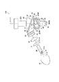
図1に示すように、投写型映像表示装置100は、光源10と、ロッドインテグレータ20と、偏光変換素子31と、狭帯域偏光状態調整素子32と、レンズ群(レンズ41、レンズ42、レンズ43)と、プリズム50と、プリズム60と、プリズム70と、プリズム80と、プリズム90と、複数のDMD;Digital Micromirror Device(DMD200R、DMD200G及びDMD200B)と、投写レンズユニット300とを有する。
As shown in FIG. 1, the
なお、第1実施形態では、光源10、プリズム群及びDMD群は、照明装置を構成する。すなわち、照明装置は、投写型映像表示装置100から投写レンズユニット300を除いた構成を有する。
In the first embodiment, the
光源10は、白色光を発するUHPランプやキセノンランプなどである。すなわち、光源10が発する光は、赤成分光R、緑成分光G及び青成分光Bを含む。また、光源10が発する光は、青成分光Bと緑成分光Gとの間の波長帯を有するシアン成分光Cy、緑成分光Gと赤成分光Rとの間の波長帯を有する黄成分光Yeを含む。
The
ロッドインテグレータ20は、光入射面と、光出射面と、光入射面の外周から光出射面の外周に亘って設けられる光反射側面とを有する。ロッドインテグレータ20は、光源10から出射された光を均一化する。すなわち、ロッドインテグレータ20は、光反射側面で光を反射することによって、光源10から出射された光を均一化する。
The
偏光変換素子31は、光源10が発する光の偏光方向を単一の偏光方向(例えば、P偏光方向)に揃えるPBS31A(Polarized Beam Splitter)及び位相差板31Bを有する。
The
狭帯域偏光状態調整素子32は、光源10から出射される光の波長帯のうち、所定波長帯の光の偏光状態を調整する。狭帯域偏光状態調整素子32は、光源10から出射された光の光路上において、偏光変換素子31と色分離部との間に設けられる。
The narrow-band polarization
なお、第1実施形態では、色分離部は、後述するように、プリズム70及びプリズム80によって構成される。また、所定波長帯は、色分離部に導かれた光を色分離部が分離する境界の波長(分離波長)を含む。
In the first embodiment, the color separation unit includes a
具体的には、狭帯域偏光状態調整素子32は、自素子に印加される電圧に応じて、所定波長帯の光の偏光状態のみを調整する。一方で、狭帯域偏光状態調整素子32は、自素子に印加される電圧によらずに、他の波長帯の光の偏光状態を調整しない。
Specifically, the narrow band polarization
第1実施形態では、所定波長帯を有する光は、シアン成分光Cy及び黄成分光Yeである。一方で、他の波長帯の光は、赤成分光R、緑成分光G及び青成分光Bである。 In the first embodiment, light having a predetermined wavelength band is cyan component light Cy and yellow component light Ye. On the other hand, light of other wavelength bands is red component light R, green component light G, and blue component light B.
例えば、狭帯域偏光状態調整素子32は、シアン成分光Cy及び黄成分光Yeの偏光方向を回転させない状態と、シアン成分光Cy及び黄成分光Yeの偏光方向を90°回転させる状態とを選択的に切り替え可能に構成される。又は、狭帯域偏光状態調整素子32は、0〜90°の範囲内において、シアン成分光Cy及び黄成分光Yeの偏光状態を調整してもよい。
For example, the narrowband polarization
レンズ群(レンズ41、レンズ42、レンズ43)は、ロッドインテグレータ20で均一化された光の拡大を抑制しながら、ロッドインテグレータ20で均一化された光を各DMD200に略結像するためのレンズである。
The lens group (
プリズム50は、透光性部材によって構成されており、面51及び面52を有する。プリズム50(面51)とプリズム60(面61)との間にはエアギャップが設けられており、レンズ群から出射された光が面51に入射する角度(入射角)は全反射角よりも大きいため、レンズ群から出射された光は面51で反射される。一方で、プリズム50(面52)とプリズム70(面71)との間にはエアギャップが設けられるが、レンズ群から出射される光が面52に入射する角度(入射角)は全反射角よりも小さいため、面51で反射された光は面52を透過する。
The
プリズム60は、透光性部材によって構成されており、面61を有する。
The
プリズム70は、透光性部材によって構成されており、面71及び面72を有する。プリズム50(面52)とプリズム70(面71)との間にはエアギャップが設けられており、面72で反射された赤成分光R及びDMD200Rから出射された赤成分光Rが面71に入射する角度(入射角)が全反射角よりも大きいため、面72で反射された赤成分光R及びDMD200Rから出射された赤成分光Rは面71で反射される。
The
面72は、緑成分光G及び青成分光Bを透過して、赤成分光Rを反射するダイクロイックミラー面である。従って、面51で反射された光のうち、緑成分光G及び青成分光Bは面72を透過し、赤成分光Rは面72で反射される。面71で反射された赤成分光Rは面72で反射される。
The
プリズム80は、透光性部材によって構成されており、面81及び面82を有する。プリズム70(面72)とプリズム80(面81)との間にはエアギャップが設けられており、面81を透過して面82で反射された青成分光B及びDMD200Bから出射された青成分光Bが再び面81に入射する角度(入射角)が全反射角よりも大きいため、面81を透過して面82で反射された青成分光B及びDMD200Bから出射された青成分光Bは面81で反射される。一方で、DMD200Bから出射されて面81で反射された後に面82で反射された青成分光Bが再び面81に入射する角度(入射角)が全反射角よりも小さいため、DMD200Bから出射されて面81で反射された後に面82で反射された青成分光Bは面81を透過する。
The
面82は、緑成分光Gを透過して、青成分光Bを反射するダイクロイックミラー面である。従って、面81を透過した光のうち、緑成分光Gは面82を透過し、青成分光Bは面82で反射される。面81で反射された青成分光Bは面82で反射される。DMD200Gから出射された緑成分光Gは面82を透過する。
The
ここで、プリズム70は、面72によって、緑成分光G及び青成分光Bを含む合成光と赤成分光Rとに白色光を分離する。プリズム80は、面82によって、緑成分光Gと青成分光Bとに合成光を分離する。すなわち、プリズム70及びプリズム80は、各色成分光を分離する色分離部として機能する。
Here, the
なお、第1実施形態では、プリズム70の面72のカットオフ波長は、赤成分光Rに相当する波長帯と緑成分光Gに相当する波長帯との間に設けられる。すなわち、プリズム70の面72のカットオフ波長は、黄成分光Yeの波長帯に設けられる。
In the first embodiment, the cutoff wavelength of the
また、第1実施形態では、プリズム80の面82のカットオフ波長は、緑成分光Gに相当する波長帯と青成分光Bに相当する波長帯との間に設けられる。すなわち、プリズム80の面82のカットオフ波長は、シアン成分光Cyの波長帯に設けられる。
In the first embodiment, the cutoff wavelength of the
一方で、プリズム80は、緑成分光Gと青成分光Bとを面82によって合成する。プリズム70は、緑成分光G及び青成分光Bを含む合成光と赤成分光Rとを面72によって合成する。すなわち、プリズム70及びプリズム80は、各色成分光を合成する色合成部として機能する。
On the other hand, the
プリズム90は、透光性部材によって構成されており、面91を有する。面91は、緑成分光Gを透過するように構成されている。なお、DMD200Gへ入射する緑成分光G及びDMD200Gから出射された緑成分光Gは面91を透過する。
The
DMD200R、DMD200G及びDMD200Bは、複数の微少ミラーによって構成されており、複数の微少ミラーは可動式である。各微少ミラーは、基本的に1画素に相当する。DMD200Rは、各微少ミラーの角度を変更することによって、投写レンズユニット300側に赤成分光Rを反射するか否かを切り替える。同様に、DMD200G及びDMD200Bは、各微少ミラーの角度を変更することによって、投写レンズユニット300側に緑成分光G及び青成分光Bを反射するか否かを切り替える。
DMD200R, DMD200G, and DMD200B are configured by a plurality of micromirrors, and the plurality of micromirrors are movable. Each minute mirror basically corresponds to one pixel. The DMD 200R switches whether to reflect the red component light R toward the
投写レンズユニット300は、プリズム90から出射された光(映像光)を投写面上に投写する。
The
(狭帯域偏光状態調整素子の構成)
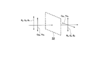
以下において、第1実施形態に係る狭帯域偏光状態調整素子の構成について、図面を参照しながら説明する。図2及び図3は、第1実施形態に係る狭帯域偏光状態調整素子32の近傍を示す図である。
(Configuration of narrow-band polarization adjustment element)
Hereinafter, the configuration of the narrowband polarization state adjusting element according to the first embodiment will be described with reference to the drawings. 2 and 3 are views showing the vicinity of the narrowband polarization
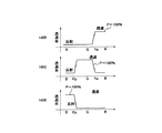
図2に示すように、狭帯域偏光状態調整素子32は、第1状態、例えば、自素子に電圧が印可されていない状態において、シアン成分光Cy及び黄成分光Yeの偏光状態を調整せずに透過する。すなわち、狭帯域偏光状態調整素子32の光出射側において、シアン成分光Cy及び黄成分光Yeの偏光状態は、赤成分光R、緑成分光G及び青成分光Bの偏光状態と同じである。
As shown in FIG. 2, the narrow-band polarization
図3に示すように、狭帯域偏光状態調整素子32は、第2状態、例えば、自素子に電圧が印可された状態において、シアン成分光Cy及び黄成分光Yeの偏光状態を調整して透過する。すなわち、狭帯域偏光状態調整素子32の光出射側において、シアン成分光Cy及び黄成分光Yeの偏光状態は、赤成分光R、緑成分光G及び青成分光Bの偏光状態と異なっている。
As shown in FIG. 3, the narrow-band polarization
上述したように、狭帯域偏光状態調整素子32は、0〜90°の範囲内において、シアン成分光Cy及び黄成分光Yeの偏光状態を調整してもよい。
As described above, the narrowband polarization
このように、狭帯域偏光状態調整素子32は、狭帯域偏光状態調整素子32の光出射側において、自素子に印可される電圧に応じて、シアン成分光Cy及び黄成分光Yeに含まれるP偏光成分及びS偏光成分の比率を制御する。
As described above, the narrowband polarization
なお、狭帯域偏光状態調整素子32によって偏光状態が調整される所定波長帯は、黄成分光Yeの波長帯に設けられる面72のカットオフ波長を含む。また、狭帯域偏光状態調整素子32によって偏光状態が調整される所定波長帯は、シアン成分光Cyの波長帯に設けられる面82のカットオフ波長を含む。
Note that the predetermined wavelength band whose polarization state is adjusted by the narrowband polarization
(カットオフ波長のシフト)
以下において、第1実施形態に係るカットオフ波長のシフトについて説明する。ダイクロイック面(プリズム70の面72及びプリズム80の面82)のカットオフ波長は、入射光の偏光状態に応じてシフトする。具体的には、P偏光成分が多いほど、ダイクロイック面を透過する透過光が多くなるように、ダイクロイック面のカットオフ波長がシフトする。S偏光成分が多いほど、ダイクロイック面で反射する反射光が多くなるように、ダイクロイック面のカットオフ波長がシフトする。
(Cutoff wavelength shift)
Hereinafter, the shift of the cutoff wavelength according to the first embodiment will be described. The cutoff wavelengths of the dichroic surfaces (the
例えば、緑成分光Gと赤成分光Rとを分離するプリズム70の面72では、緑成分光Gが透過光であるため、黄成分光Yeに含まれるP偏光成分が多いほど、緑成分光Gに重畳される黄成分光Yeが多い。緑成分光Gと赤成分光Rとを分離するプリズム70の面72では、赤成分光Rが反射光であるため、黄成分光Yeに含まれるS偏光成分が多いほど、赤成分光Rに重畳される黄成分光Yeが多い。
For example, on the
一方で、青成分光Bと緑成分光Gとを分離するプリズム80の面82では、緑成分光Gが透過光であるため、シアン成分光Cyに含まれるP偏光成分が多いほど、緑成分光Gに重畳されるシアン成分光Cyが多い。一方で、青成分光Bと緑成分光Gとを分離するプリズム80の面82では、青成分光Bが反射光であるため、シアン成分光Cyに含まれるS偏光成分が多いほど、青成分光Bに重畳されるシアン成分光Cyが多い。
On the other hand, on the
(偏光状態と色再現範囲との関係)
以下において、第1実施形態に係る偏光状態と色再現範囲との関係について、図面を参照しながら説明する。図4〜図9は、第1実施形態に係る偏光状態と色再現範囲との関係を示す図である。
(Relationship between polarization state and color reproduction range)
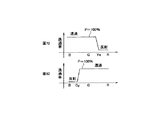
Hereinafter, the relationship between the polarization state and the color reproduction range according to the first embodiment will be described with reference to the drawings. 4 to 9 are diagrams illustrating the relationship between the polarization state and the color reproduction range according to the first embodiment.
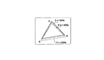
(1)P偏光成分の比率が100%であるケース
第1に、シアン成分光Cy及び黄成分光Yeに含まれるP偏光成分の比率が100%であるケースについて説明する。
(1) Case where the ratio of the P-polarized light component is 100% First, a case where the ratio of the P-polarized light component contained in the cyan component light Cy and the yellow component light Ye is 100% will be described.
図4に示すように、プリズム70の面72では、黄成分光Yeに含まれるP偏光成分の比率が100%であるため、黄成分光Yeは、主として緑成分光Gに重畳される。また、プリズム80の面82では、シアン成分光Cyに含まれるP偏光成分の比率が100%であるため、シアン成分光Cyは、主として緑成分光Gに重畳される。
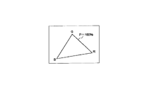
As shown in FIG. 4, since the ratio of the P-polarized component contained in the yellow component light Ye is 100% on the
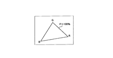
このようなケースでは、図5に示す色再現範囲が実現される。なお、後述する例では、P偏光成分の比率が100%であるケースを基準にして、色再現範囲について説明する。 In such a case, the color reproduction range shown in FIG. 5 is realized. In the example described later, the color reproduction range will be described based on the case where the ratio of the P-polarized light component is 100%.
(2)P偏光成分の比率が50%であり、S偏光成分の比率が50%であるケース
第2に、シアン成分光Cy及び黄成分光Yeに含まれるP偏光成分の比率が50%であり、S偏光成分の比率が50%であるケースについて説明する。
(2) Case where the ratio of the P polarization component is 50% and the ratio of the S polarization component is 50% Second, the ratio of the P polarization component included in the cyan component light Cy and the yellow component light Ye is 50%. A case where the ratio of the S polarization component is 50% will be described.
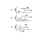
図6に示すように、プリズム70の面72では、黄成分光Yeが50%のP偏光成分及び50%のS偏光成分を含むため、黄成分光Yeは、赤成分光R及び緑成分光Gの双方に重畳される。言い換えると、黄成分光Yeは、赤成分光Rの光路又は緑成分光Gの光路に分配される。また、プリズム80の面82では、シアン成分光Cyが50%のP偏光成分及び50%のS偏光成分を含むため、シアン成分光Cyは、緑成分光G及び青成分光Bの双方に重畳される。言い換えると、黄成分光Yeは、緑成分光Gの光路又は青成分光Bの光路に分配される。
As shown in FIG. 6, since the yellow component light Ye includes 50% P-polarized component and 50% S-polarized component on the
このようなケースでは、図7に示す色再現範囲が実現される。シアン成分光Cy及び黄成分光Yeの一部が緑成分光Gに重畳されないため、図7に示す色再現範囲では、図5に示す色再現範囲よりも緑色の純度が上昇する。これに対して、シアン成分光Cyの一部が青成分光Bに重畳されるため、図7に示す色再現範囲では、図5に示す色再現範囲よりも青色の純度が低下する。同様に、黄成分光Yeの一部が赤成分光Rに重畳されるため、図7に示す色再現範囲では、図5に示す色再現範囲よりも赤色の純度が低下する。 In such a case, the color reproduction range shown in FIG. 7 is realized. Since some of the cyan component light Cy and the yellow component light Ye are not superimposed on the green component light G, the purity of green is higher in the color reproduction range shown in FIG. 7 than in the color reproduction range shown in FIG. On the other hand, since a part of the cyan component light Cy is superimposed on the blue component light B, the purity of blue is lower in the color reproduction range shown in FIG. 7 than in the color reproduction range shown in FIG. Similarly, since a part of the yellow component light Ye is superimposed on the red component light R, the purity of red is lower in the color reproduction range shown in FIG. 7 than in the color reproduction range shown in FIG.
(3)S偏光成分の比率が100%であるケース
第3に、シアン成分光Cy及び黄成分光Yeに含まれるS偏光成分の比率が100%であるケースについて説明する。
(3) Case where S-polarized component ratio is 100% Third, a case where the ratio of S-polarized component contained in cyan component light Cy and yellow component light Ye is 100% will be described.
図8に示すように、プリズム70の面72では、黄成分光Yeに含まれるS偏光成分の比率が100%であるため、黄成分光Yeは、主として赤成分光Rに重畳される。また、プリズム80の面82では、シアン成分光Cyに含まれるS偏光成分の比率が100%であるため、シアン成分光Cyは、主として青成分光Bに重畳される。
As shown in FIG. 8, on the
このようなケースでは、図9に示す色再現範囲が実現される。シアン成分光Cy及び黄成分光Yeがほとんど緑成分光Gに重畳されないため、図9に示す色再現範囲では、図5に示す色再現範囲よりも緑色の純度がさらに上昇する。すなわち、図9に示す色再現範囲では、図7に示す色再現範囲よりも緑色の純度が上昇する。 In such a case, the color reproduction range shown in FIG. 9 is realized. Since the cyan component light Cy and the yellow component light Ye are hardly superimposed on the green component light G, the purity of green is further increased in the color reproduction range shown in FIG. 9 than in the color reproduction range shown in FIG. That is, in the color reproduction range shown in FIG. 9, the green purity is higher than that in the color reproduction range shown in FIG.
これに対して、黄成分光Yeが主として赤成分光Rに重畳されるため、図9に示す色再現範囲では、図5に示す色再現範囲よりも赤色の純度がさらに低下する。同様に、シアン成分光Cyが青成分光Bに主として重畳されるため、図9に示す色再現範囲では、図5に示す色再現範囲よりも青色の純度がさらに低下する。すなわち、図9に示す色再現範囲では、図7に示す色再現範囲よりも赤色及び青色の純度が低下する。 On the other hand, since the yellow component light Ye is mainly superimposed on the red component light R, the purity of red is further reduced in the color reproduction range shown in FIG. 9 than in the color reproduction range shown in FIG. Similarly, since the cyan component light Cy is mainly superimposed on the blue component light B, the purity of blue is further lowered in the color reproduction range shown in FIG. 9 than in the color reproduction range shown in FIG. That is, in the color reproduction range shown in FIG. 9, the red and blue purity is lower than that in the color reproduction range shown in FIG.
(作用及び効果)
第1実施形態では、偏光変換素子31と色分離部(プリズム70及びプリズム80)との間に設けられた狭帯域偏光状態調整素子32は、光源10から出射される光の波長帯のうち、シアン成分光Cy及び黄成分光Yeの偏光状態を調整する。一方で、色分離部に導かれた光を分離する波長(面72及び面82のカットオフ波長)は、色分離部に導かれた光の偏光状態に応じてシフトする。
(Function and effect)
In the first embodiment, the narrow-band polarization
具体的には、赤成分光R、緑成分光G及び青成分光Bに重畳すべきシアン成分光Cy及び黄成分光Yeに含まれるP偏光成分及びS偏光成分の比率を狭帯域偏光状態調整素子32によって制御することによって、投写面に投写される映像の色再現範囲を切り替えることができる。
Specifically, the ratio of the P-polarized component and the S-polarized component contained in the cyan component light Cy and yellow component light Ye to be superimposed on the red component light R, green component light G, and blue component light B is adjusted in the narrowband polarization state. By controlling with the
これによって、DMD200に導かれる総光量の低下を抑制しながら、投写面に投写される映像の色再現範囲を切り替えることができる。
As a result, the color reproduction range of the image projected on the projection plane can be switched while suppressing a decrease in the total light amount guided to the
ここで、狭帯域偏光状態調整素子32によって偏光状態が制御される所定波長帯域は、面72及び面82のカットオフ波長を含む。従って、赤成分光R、緑成分光G及び青成分光Bの純度をある程度保ちながら、赤成分光R、緑成分光G及び青成分光Bの境界の波長を有する光(シアン成分光Cy及び黄成分光Ye)を適切に各光路に分配することができる。
Here, the predetermined wavelength band in which the polarization state is controlled by the narrowband polarization
ここで、DMD200は、微少ミラーの角度を変更することによって、色成分光を変調するように構成される。従って、反射型光変調素子としてDMD200が用いられるケースでは、各色成分光の偏光状態について注意を払わないことが一般的であることに留意すべきである。
Here, the
[第1変更例]
以下において、第1実施形態の第1変更例について、図面を参照しながら説明する。以下においては、第1実施形態との相違点について主として説明する。
[First modification]
Hereinafter, a first modification of the first embodiment will be described with reference to the drawings. In the following, differences from the first embodiment will be mainly described.
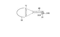
具体的には、第1実施形態では、ロッドインテグレータ20の光入射側に偏光変換素子31が設けられる。これに対して、変更例1では、図10に示すように、ロッドインテグレータ20の光出射側に偏光変換素子31(PBS31A及び位相差板31B)が設けられる。
Specifically, in the first embodiment, the
例えば、光源10に設けられたリフレクタの断面が楕円形状を有しており、リフレクタが光を集光するように構成されているケースにおいて、第1変更例を適用することが好ましい。
For example, it is preferable to apply the first modified example in a case where the reflector provided in the
[第2変更例]
以下において、第1実施形態の第2変更例について、図面を参照しながら説明する。以下においては、第1実施形態及び第1変更例との相違点について主として説明する。
[Second modification]
Hereinafter, a second modification of the first embodiment will be described with reference to the drawings. In the following, differences from the first embodiment and the first modification will be mainly described.
具体的には、第1実施形態及び第1変更例では、光源10から出射される光の集光について特に触れていない。これに対して、第2変更例では、図11に示すように、光源10から出射される光を集光するコンデンサレンズ11が設けられる。コンデンサレンズ11は、光源10から出射される光をロッドインテグレータ20の光入射面に集光する。
Specifically, in the first embodiment and the first modified example, no particular mention is made of condensing light emitted from the
例えば、光源10に設けられたリフレクタの断面が放物線形状を有しており、リフレクタが光を平行光で反射するように構成されているケースにおいて、第2変更例を適用することが好ましい。
For example, in the case where the cross section of the reflector provided in the
[第3変更例]
以下において、第1実施形態の第3変更例について、図面を参照しながら説明する。以下においては、第1実施形態との相違点について主として説明する。
[Third Modification]
Hereinafter, a third modification of the first embodiment will be described with reference to the drawings. In the following, differences from the first embodiment will be mainly described.
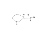
具体的には、第3変更例では、光源10から出射される光の偏光方向の揃え方が第1実施形態及び第1変更例と異なる。第3変更例では、図12に示すように、偏光変換素子31に代えて、ミラー12、1/4λ位相差板35及び反射型偏光板36が設けられる。
Specifically, in the third modified example, the alignment method of the polarization direction of the light emitted from the
ミラー12は、ロッドインテグレータ20の光入射面に設けられる。1/4λ位相差板35は、光の位相を1/4λ変化させる。反射型偏光板36は、一の偏光方向を透過して、他の偏光方向を反射する。
The
ロッドインテグレータ20に導かれた光は、一の偏光方向に揃うまで、ミラー12及び反射型偏光板36で反射される。すなわち、ロッドインテグレータ20に導かれた光は、一の偏光方向に揃うまで、ロッドインテグレータ20を往復する。これによって、ロッドインテグレータ20に導かれた光は、単一の偏光方向に揃えられる。
The light guided to the
[第4変更例]
以下において、第1実施形態の第4変更例について、図面を参照しながら説明する。以下においては、第1実施形態との相違点について主として説明する。
[Fourth modification]
Hereinafter, a fourth modification of the first embodiment will be described with reference to the drawings. In the following, differences from the first embodiment will be mainly described.
具体的には、第4変更例では、光源10から出射される光の均一化方法及び偏光方向の揃え方が第1実施形態及び第1変更例と異なる。第4変更例では、図13に示すように、ロッドインテグレータ20及び偏光変換素子31に代えて、フライアイレンズユニット37と、PBSアレイ38と、コンデンサレンズ群(レンズ45及びレンズ46)が設けられる。
Specifically, in the fourth modification example, the method for equalizing the light emitted from the
フライアイレンズユニット37は、フライアイレンズ37A及びフライアイレンズ37Bによって構成されており、光源10から出射される光を均一化する。PBSアレイ38は、フライアイレンズユニット37から出射された光を単一の偏光方向に揃えるPBS38A及び位相差板38Bを有する。レンズ45及びレンズ46は、PBSアレイ38から出射された光を集光する。
The fly
[第2実施形態]
以下において、第2実施形態について、図面を参照しながら説明する。以下においては、第1実施形態との相違点について主として説明する。
[Second Embodiment]
Hereinafter, the second embodiment will be described with reference to the drawings. In the following, differences from the first embodiment will be mainly described.
具体的には、第1実施形態では、色分離部として、色分離合成プリズム群(プリズム70、プリズム80)が設けられる。これに対して、第2実施形態では、色分離部として、カラーホイールが設けられる。
Specifically, in the first embodiment, a color separation / combination prism group (
(投写型映像表示装置)
以下において、第2実施形態に係る投写型映像表示装置について、図面を参照しながら説明する。図14は、第2実施形態に係る投写型映像表示装置100を示す図である。第2実施形態では、反射型光変調素子として、DMD(Digital Micromirror Device)を有する投写型映像表示装置100を例示する。なお、図14では、図1と同様の構成について、同様の符号を付している。
(Projection-type image display device)
Hereinafter, a projection display apparatus according to the second embodiment will be described with reference to the drawings. FIG. 14 is a diagram showing a
図14に示すように、投写型映像表示装置100は、第1実施形態と同様に、光源10と、ロッドインテグレータ20と、偏光変換素子31と、狭帯域偏光状態調整素子32と、レンズ群(レンズ41、レンズ42、レンズ43)と、DMD200と、投写レンズユニット300とを有する。また、投写型映像表示装置100は、カラーホイール140と、プリズム160と、プリズム170と、非球面ミラー180とを有する。
As shown in FIG. 14, the
カラーホイール140は、回転可能に構成されており、円盤形状の盤面を有する。カラーホイール140に設けられた盤面の法線L1は、光源10から出射された光の光軸L2に対して傾いている。
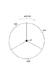
The
具体的には、カラーホイール140は、図15に示すように、回転軸141を中心として、回転可能に構成される。カラーホイール140に設けられた円盤形状の盤面は、赤透過領域142Rと、緑透過領域142Gと、青透過領域142Bとを含む。赤透過領域142Rは、赤成分光Rを透過し、他の光を遮光する領域である。緑透過領域142Gは、緑成分光Gを透過し、他の光を遮光する領域である。青透過領域142Bは、青成分光Bを透過し、他の光を遮光する領域である。
Specifically, the
第2実施形態では、例えば、各透過領域が設けられる順序は、所定方向Aに沿って、赤透過領域142R、青透過領域142B、緑透過領域142Gである。
In the second embodiment, for example, the order in which each transmission region is provided is the
プリズム160は、光透過性部材によって構成されており、面161を有する。プリズム170は、光透過性部材によって構成されており、面171を有する。
The
プリズム160(面161)とプリズム170(面171)との間にはエアギャップが設けられる。レンズ群から出射される光が面161に入射する角度(入射角)が全反射角よりも大きいため、レンズ群から出射される光は面161で反射される。DMD200から出射された光が面161に入射する角度(入射角)が全反射角よりも小さいため、DMD200から出射される光は面161を透過する。
An air gap is provided between the prism 160 (surface 161) and the prism 170 (surface 171). Since the angle at which the light emitted from the lens group enters the surface 161 (incident angle) is larger than the total reflection angle, the light emitted from the lens group is reflected by the
非球面ミラー180は、投写レンズユニット300から出射された光(映像光)を投写面側に反射する。投写レンズユニット300から出射された光(映像光)は、非球面ミラー180によって拡大される。
The aspherical mirror 180 reflects light (image light) emitted from the
(透過波長のシフト)
以下において、第2実施形態に係る透過波長のシフトについて説明する。透過領域(赤透過領域142R、緑透過領域142G、青透過領域142B)の透過波長は、入射光の偏光状態に応じてシフトする。
(Transmission wavelength shift)
Hereinafter, the shift of the transmission wavelength according to the second embodiment will be described. The transmission wavelengths of the transmission regions (
例えば、赤透過領域142Rでは、黄成分光Yeに含まれるP偏光成分が多いほど、赤成分光Rに重畳される黄成分光Yeが少ない。赤透過領域142Rでは、黄成分光Yeに含まれるS偏光成分が多いほど、赤成分光Rに重畳される黄成分光Yeが多い。
For example, in the
緑透過領域142Gでは、シアン成分光Cy及び黄成分光Yeに含まれるP偏光成分が多いほど、緑成分光Gに重畳されるシアン成分光Cy及び黄成分光Yeが多い。緑透過領域142Gでは、シアン成分光Cy及び黄成分光Yeに含まれるS偏光成分が多いほど、緑成分光Gに重畳されるシアン成分光Cy及び黄成分光Yeが少ない。
In the
青透過領域142Bでは、シアン成分光Cyに含まれるP偏光成分が多いほど、青成分光Bに重畳されるシアン成分光Cyが少ない。青透過領域142Bでは、シアン成分光Cyに含まれるS偏光成分が多いほど、青成分光Bに重畳されるシアン成分光Cyが多い。
In the
(偏光状態と色再現範囲との関係)
以下において、第2実施形態に係る偏光状態と色再現範囲との関係について、図面を参照しながら説明する。図16〜図21は、第2実施形態に係る偏光状態と色再現範囲との関係を示す図である。
(Relationship between polarization state and color reproduction range)
Hereinafter, the relationship between the polarization state and the color reproduction range according to the second embodiment will be described with reference to the drawings. 16 to 21 are diagrams illustrating the relationship between the polarization state and the color reproduction range according to the second embodiment.
(1)P偏光成分の比率が100%であるケース
第1に、シアン成分光Cy及び黄成分光Yeに含まれるP偏光成分の比率が100%であるケースについて説明する。
(1) Case where the ratio of the P-polarized light component is 100% First, a case where the ratio of the P-polarized light component contained in the cyan component light Cy and the yellow component light Ye is 100% will be described.
図16に示すように、赤透過領域142Rでは、黄成分光Yeに含まれるP偏光成分の比率が100%であるため、赤成分光Rに重畳される黄成分光Yeが少ない。緑透過領域142Gでは、シアン成分光Cy及び黄成分光Yeに含まれるP偏光成分の比率が100%であるため、緑成分光Gに重畳されるシアン成分光Cy及び黄成分光Yeが多い。青透過領域142Bでは、シアン成分光Cyに含まれるP偏光成分の比率が100%であるため、青成分光Bに重畳されるシアン成分光Cyが少ない。
As shown in FIG. 16, in the
このようなケースでは、図17に示す色再現範囲が実現される。なお、後述する例では、P偏光成分の比率が100%であるケースを基準にして、色再現範囲について説明する。 In such a case, the color reproduction range shown in FIG. 17 is realized. In the example described later, the color reproduction range will be described based on the case where the ratio of the P-polarized light component is 100%.
(2)P偏光成分の比率が50%であり、S偏光成分の比率が50%であるケース
第2に、シアン成分光Cy及び黄成分光Yeに含まれるP偏光成分の比率が50%であり、S偏光成分の比率が50%であるケースについて説明する。
(2) Case where the ratio of the P polarization component is 50% and the ratio of the S polarization component is 50% Second, the ratio of the P polarization component included in the cyan component light Cy and the yellow component light Ye is 50%. A case where the ratio of the S polarization component is 50% will be described.
図18に示すように、赤透過領域142Rでは、黄成分光Yeが50%のP偏光成分及び50%のS偏光成分を含むため、赤成分光Rに重畳される黄成分光Yeが増大する。緑透過領域142Gでは、シアン成分光Cy及び黄成分光Yeが50%のP偏光成分及び50%のS偏光成分を含むため、緑成分光Gに重畳されるシアン成分光Cy及び黄成分光Yeが減少する。青透過領域142Bでは、シアン成分光Cyが50%のP偏光成分及び50%のS偏光成分を含むため、青成分光Bに重畳されるシアン成分光Cyが増大する。
As shown in FIG. 18, in the
このようなケースでは、図19に示す色再現範囲が実現される。緑成分光Gに重畳されるシアン成分光Cy及び黄成分光Yeが減少するため、図19に示す色再現範囲では、図17に示す色再現範囲よりも緑色の純度が上昇する。これに対して、赤成分光Rに重畳される黄成分光Yeが増大し、青成分光Bに重畳されるシアン成分光Cyが増大するため、図19に示す色再現範囲では、図17に示す色再現範囲よりも赤色及び青色の純度が低下する。 In such a case, the color reproduction range shown in FIG. 19 is realized. Since the cyan component light Cy and the yellow component light Ye superimposed on the green component light G are reduced, the purity of green is higher in the color reproduction range shown in FIG. 19 than in the color reproduction range shown in FIG. On the other hand, the yellow component light Ye superimposed on the red component light R increases and the cyan component light Cy superimposed on the blue component light B increases. Therefore, in the color reproduction range shown in FIG. The purity of red and blue is lower than the color reproduction range shown.
(3)S偏光成分の比率が100%であるケース
第3に、シアン成分光Cy及び黄成分光Yeに含まれるS偏光成分の比率が100%であるケースについて説明する。
(3) Case where S-polarized component ratio is 100% Third, a case where the ratio of S-polarized component contained in cyan component light Cy and yellow component light Ye is 100% will be described.
図20に示すように、赤透過領域142Rでは、黄成分光Yeに含まれるS偏光成分の比率が100%であるため、赤成分光Rに重畳される黄成分光Yeが多い。緑透過領域142Gでは、シアン成分光Cy及び黄成分光Yeに含まれるS偏光成分の比率が100%であるため、緑成分光Gに重畳されるシアン成分光Cy及び黄成分光Yeが少ない。青透過領域142Bでは、シアン成分光Cyに含まれるS偏光成分の比率が100%であるため、青成分光Bに重畳されるシアン成分光Cyが多い。
As shown in FIG. 20, in the
このようなケースでは、図21に示す色再現範囲が実現される。緑成分光Gに重畳されるシアン成分光Cy及び黄成分光Yeがさらに減少するため、図21に示す色再現範囲では、図17に示す色再現範囲よりも緑色の純度がさらに上昇する。すなわち、図21に示す色再現範囲では、図19に示す色再現範囲よりも緑色の純度が上昇する。 In such a case, the color reproduction range shown in FIG. 21 is realized. Since the cyan component light Cy and the yellow component light Ye superimposed on the green component light G are further reduced, the purity of green is further increased in the color reproduction range shown in FIG. 21 than in the color reproduction range shown in FIG. That is, in the color reproduction range shown in FIG. 21, the purity of green is higher than that in the color reproduction range shown in FIG.
これに対して、赤成分光Rに重畳される黄成分光Yeがさらに増大し、青成分光Bに重畳されるシアン成分光Cyがさらに増大するため、図21に示す色再現範囲では、図17に示す色再現範囲よりも赤色及び青色の純度がさらに低下する。すなわち、図21に示す色再現範囲では、図19に示す色再現範囲よりも赤色及び青色の純度が低下する。 On the other hand, the yellow component light Ye superimposed on the red component light R further increases and the cyan component light Cy superimposed on the blue component light B further increases. Therefore, in the color reproduction range shown in FIG. The purity of red and blue is further lowered than the color reproduction range shown in FIG. That is, in the color reproduction range shown in FIG. 21, the purity of red and blue is lower than that in the color reproduction range shown in FIG.
(作用及び効果)
第2実施形態では、偏光変換素子31と色分離部(カラーホイール140)との間に設けられた狭帯域偏光状態調整素子32は、光源10から出射される光の波長帯のうち、シアン成分光Cy及び黄成分光Yeの偏光状態を調整する。一方で、カラーホイール140に導かれた光を分離する波長(赤透過領域142R、緑透過領域142G及び青透過領域142Bの透過波長)は、カラーホイール140に導かれた光の偏光状態に応じてシフトする。
(Function and effect)
In the second embodiment, the narrow-band polarization
具体的には、赤成分光R、緑成分光G及び青成分光Bに重畳すべきシアン成分光Cy及び黄成分光Yeの光量を狭帯域偏光状態調整素子32によって制御することによって、投写面に投写される映像の色再現範囲を切り替えることができる。
Specifically, by controlling the light amounts of the cyan component light Cy and the yellow component light Ye to be superimposed on the red component light R, the green component light G, and the blue component light B by the narrowband polarization
これによって、DMD200に導かれる総光量の低下を抑制しながら、投写面に投写される映像の色再現範囲を切り替えることができる。
As a result, the color reproduction range of the image projected on the projection plane can be switched while suppressing a decrease in the total light amount guided to the
[その他の実施形態]
本発明は上述した実施形態によって説明したが、この開示の一部をなす論述及び図面は、この発明を限定するものであると理解すべきではない。この開示から当業者には様々な代替実施形態、実施例及び運用技術が明らかとなろう。
[Other Embodiments]
Although the present invention has been described with reference to the above-described embodiments, it should not be understood that the descriptions and drawings constituting a part of this disclosure limit the present invention. From this disclosure, various alternative embodiments, examples and operational techniques will be apparent to those skilled in the art.
実施形態では、狭帯域偏光状態調整素子32は、シアン成分光Cy及び黄成分光Yeの偏光状態を調整するが、実施形態はこれに限定されるものではない。
In the embodiment, the narrow band polarization
例えば、狭帯域偏光状態調整素子32は、シアン成分光Cyの偏光状態のみを調整してもよい。また、狭帯域偏光状態調整素子32は、黄成分光Yeの偏光状態のみを調整してもよい。
For example, the narrowband polarization
さらに、狭帯域偏光状態調整素子32に代えて、シアン成分光Cyの偏光状態のみを調整する狭帯域偏光状態調整素子及び黄成分光Yeの偏光状態のみを調整する狭帯域偏光状態調整素子が設けられていてもよい。これによって、シアン成分光Cy及び黄成分光Yeの偏光状態が独立して制御されるため、色再現範囲のバリエーションが増加する。
Further, in place of the narrowband polarization
実施形態では、反射型光変調素子として、DMD200が例示されているが、実施形態は、これに限定されるものではない。
In the embodiment, the
実施形態では、P偏光成分が多いほど、ダイクロイック面を透過する透過光が多くなるように、ダイクロイック面のカットオフ波長がシフトし、S偏光成分が多いほど、ダイクロイック面で反射する反射光が多くなるように、ダイクロイック面のカットオフ波長がシフトするケースを例示した。しかしながら、実施形態は、これに限定されるものではない。 In the embodiment, the cutoff wavelength of the dichroic surface is shifted so that the more P-polarized light component is transmitted, the more transmitted light is transmitted through the dichroic surface. The more the S-polarized component is, the more reflected light is reflected by the dichroic surface. As shown, the case where the cutoff wavelength of the dichroic surface is shifted is illustrated. However, the embodiment is not limited to this.
例えば、ダイクロイック面を構成する誘電体多層膜の構成によっては、P偏光成分が多いほど、ダイクロイック面で反射する反射光が多くなるように、ダイクロイック面のカットオフ波長がシフトしてもよい。同様に、S偏光成分が多いほど、ダイクロイック面を透過する透過光が多くなるように、ダイクロイック面のカットオフ波長がシフトしてもよい。 For example, depending on the configuration of the dielectric multilayer film constituting the dichroic surface, the cut-off wavelength of the dichroic surface may be shifted so that the greater the P-polarized component, the more reflected light is reflected from the dichroic surface. Similarly, the cutoff wavelength of the dichroic surface may be shifted so that the greater the S-polarized component, the greater the transmitted light that passes through the dichroic surface.
また、ダイクロイック面やカラーホイール面などの入射面に対する入射光の振動方向に応じて、入射面を透過する光の波長帯(透過波長帯)や入射面で反射する光の波長帯(反射波長帯)が変化することに留意すべきである。すなわち、狭帯域偏光状態調整素子32によって偏光状態が調整された結果、入射面に対する入射光の振動方向が定まるため、入射面の傾きに応じて、透過波長帯及び反射波長帯が変化することに留意すべきである。
Also, depending on the direction of vibration of the incident light with respect to the incident surface such as the dichroic surface or the color wheel surface, the wavelength band of the light transmitted through the incident surface (transmission wavelength band) or the wavelength band of the light reflected at the incident surface (reflection wavelength band) ) Should change. That is, as a result of adjusting the polarization state by the narrow-band polarization
第2実施形態では、各透過領域が設けられる順序は、所定方向Aに沿って、赤透過領域142R、青透過領域142B、緑透過領域142Gである。しかしながら、各透過領域が設けられる順序は、特に限定されるものではない。例えば、各透過領域が設けられる順序は、所定方向Aに沿って、青透過領域142B、赤透過領域142R、緑透過領域142Gであってもよい。
In the second embodiment, the order in which each transmission region is provided is the
第2実施形態は、カラーホイール140は、赤透過領域142R、緑透過領域142G及び青透過領域142Bを有する。しかしながら、実施形態は、これに限定されるものではない。カラーホイール140は、赤透過領域、緑透過領域及び青透過領域に加えて、黄透過領域、シアン透過領域及びマゼンタ透過領域の少なくても1つ以上を有していてもよい。
In the second embodiment, the
第2実施形態は、カラーホイール140は、3つの透過領域に区分けされている。しかしながら、実施形態は、これに限定されるものではない。カラーホイール140は、4つ以上の透過領域に区分けされていてもよい。例えば、カラーホイール140は、第1赤透過領域(例えば、赤光透過)、第2赤透過領域(例えば、黄光透過)、第1緑透過領域(例えば、緑光透過)、第2緑透過領域(例えば、シアン光透過)、第1青透過領域(例えば、青光透過)及び第2青透過領域(例えば、マゼンタ光透過)を有していてもよい。
In the second embodiment, the
10…光源、11…コンデンサレンズ、12…ミラー、20…ロッドインテグレータ、31…偏光変換素子、32…狭帯域偏光状態調整素子、35…1/4λ位相差板、36…反射型偏光板、37…フライアイレンズユニット、38…PBSアレイ、41〜43,45,46…レンズ、50,60,70,80,90…プリズム、100…投写型映像表示装置、140…カラーホイール、141…回転軸、142…透過領域、160,170…プリズム、180…非球面ミラー、200…DMD、300…投写レンズユニット
DESCRIPTION OF
Claims (5)
前記光源から出射される光の偏光方向を単一の偏光方向に揃える偏光変換素子と、
前記偏光変換素子によって前記単一の偏光方向に揃えられた光を分離する色分離部と、
前記光源から出射される光の波長帯のうち、所定波長帯の光の偏光状態を調整する狭帯域偏光状態調整素子とを備え、
前記狭帯域偏光状態調整素子は、前記光源から出射される光の光路上において、前記偏光変換素子と前記色分離部との間に設けられることを特徴とする照明装置。 An illumination device comprising a light source and a reflective light modulation element that modulates light emitted from the light source,
A polarization conversion element that aligns the polarization direction of light emitted from the light source with a single polarization direction;
A color separation unit that separates light aligned in the single polarization direction by the polarization conversion element;
A narrowband polarization state adjusting element for adjusting the polarization state of light in a predetermined wavelength band among the wavelength bands of light emitted from the light source;
The narrow band polarization state adjusting element is provided between the polarization conversion element and the color separation unit on an optical path of light emitted from the light source.
前記所定波長帯は、前記ダイクロイック面のカットオフ波長を含むことを特徴とする請求項1に記載の照明装置。 The color separation unit has at least a dichroic surface;
The lighting device according to claim 1, wherein the predetermined wavelength band includes a cutoff wavelength of the dichroic surface.
前記カラーホイールに設けられた前記盤面の法線は、前記光源から出射された光の光軸に対して傾いていることを特徴とする請求項1に記載の照明装置。 The color separation unit is configured to be rotatable and is a color wheel having a disk-shaped board surface,
The illumination device according to claim 1, wherein a normal line of the board surface provided on the color wheel is inclined with respect to an optical axis of light emitted from the light source.
前記光源から出射される光の偏光方向を単一の偏光方向に揃える偏光変換素子と、
前記偏光変換素子によって前記単一の偏光方向に揃えられた光を分離する色分離部と、
前記光源から出射される光の波長帯のうち、所定波長帯の光の偏光状態を調整する狭帯域偏光状態調整素子とを備え、
前記狭帯域偏光状態調整素子は、前記光源から出射される光の光路上において、前記偏光変換素子と前記色分離部との間に設けられることを特徴とする投写型映像表示装置。 A projection display apparatus comprising: a light source; a reflection light modulation element that modulates light emitted from the light source; and a projection unit that projects light emitted from the reflection light modulation element onto a projection surface. And
A polarization conversion element that aligns the polarization direction of light emitted from the light source with a single polarization direction;
A color separation unit that separates light aligned in the single polarization direction by the polarization conversion element;
A narrowband polarization state adjusting element for adjusting the polarization state of light in a predetermined wavelength band among the wavelength bands of light emitted from the light source;
The projection-type image display device, wherein the narrow-band polarization state adjustment element is provided between the polarization conversion element and the color separation unit on an optical path of light emitted from the light source.
Priority Applications (2)
| Application Number | Priority Date | Filing Date | Title |
|---|---|---|---|
| JP2009149652A JP2011007912A (en) | 2009-06-24 | 2009-06-24 | Illumination apparatus and projection display apparatus |
| US12/727,308 US8469516B2 (en) | 2009-06-24 | 2010-03-19 | Illumination apparatus and projection display apparatus |
Applications Claiming Priority (1)
| Application Number | Priority Date | Filing Date | Title |
|---|---|---|---|
| JP2009149652A JP2011007912A (en) | 2009-06-24 | 2009-06-24 | Illumination apparatus and projection display apparatus |
Publications (2)
| Publication Number | Publication Date |
|---|---|
| JP2011007912A true JP2011007912A (en) | 2011-01-13 |
| JP2011007912A5 JP2011007912A5 (en) | 2012-08-02 |
Family
ID=43380337
Family Applications (1)
| Application Number | Title | Priority Date | Filing Date |
|---|---|---|---|
| JP2009149652A Pending JP2011007912A (en) | 2009-06-24 | 2009-06-24 | Illumination apparatus and projection display apparatus |
Country Status (2)
| Country | Link |
|---|---|
| US (1) | US8469516B2 (en) |
| JP (1) | JP2011007912A (en) |
Cited By (1)
| Publication number | Priority date | Publication date | Assignee | Title |
|---|---|---|---|---|
| CN102508401A (en) * | 2011-10-25 | 2012-06-20 | 海信集团有限公司 | Light source device and projector using same |
Families Citing this family (7)
| Publication number | Priority date | Publication date | Assignee | Title |
|---|---|---|---|---|
| GB201108000D0 (en) * | 2011-05-13 | 2011-06-29 | Barco Nv | Polarization preserving dlp optical architecture |
| JP5938335B2 (en) * | 2012-11-20 | 2016-06-22 | 日立マクセル株式会社 | Projection display device |
| US9329461B2 (en) * | 2013-10-28 | 2016-05-03 | Dell Products, Lp | Hybrid light engine for projector |
| WO2015129720A1 (en) * | 2014-02-28 | 2015-09-03 | コニカミノルタ株式会社 | Color separation/synthesizing prism, and optical system and projector employing same |
| TWI575297B (en) * | 2015-01-07 | 2017-03-21 | 佳世達科技股份有限公司 | Projector |
| CN205787403U9 (en) * | 2016-05-18 | 2017-04-26 | 颜栋卿 | Stereo projection device capable of improving light utilization rate |
| CN109324465B (en) * | 2017-07-31 | 2021-12-31 | 深圳光峰科技股份有限公司 | Display apparatus and display method |
Citations (2)
| Publication number | Priority date | Publication date | Assignee | Title |
|---|---|---|---|---|
| JP2005258163A (en) * | 2004-03-12 | 2005-09-22 | Nec Viewtechnology Ltd | Projector apparatus |
| JP4286306B2 (en) * | 2006-10-31 | 2009-06-24 | 三洋電機株式会社 | Illumination device and projection display device |
Family Cites Families (7)
| Publication number | Priority date | Publication date | Assignee | Title |
|---|---|---|---|---|
| KR100400369B1 (en) * | 2000-12-28 | 2003-10-08 | 엘지전자 주식회사 | Projector |
| JP2004163714A (en) * | 2002-11-14 | 2004-06-10 | Fuji Photo Optical Co Ltd | Cross dichroic prism and reflective liquid crystal projector device using the same |
| US7083283B2 (en) * | 2003-07-22 | 2006-08-01 | Seiko Epson Corporation | Projector |
| JP3984932B2 (en) | 2003-07-23 | 2007-10-03 | Necディスプレイソリューションズ株式会社 | projector |
| JP4507162B2 (en) * | 2003-10-01 | 2010-07-21 | フジノン株式会社 | Color separation / synthesis system, color separation system, color synthesis system, and illumination optical system, projection optical system, and projection display device using the same |
| US7347562B2 (en) * | 2004-05-21 | 2008-03-25 | Jds Uniphase Corporation | Two-panel liquid-crystal-on-silicon color management system |
| TW200935162A (en) * | 2008-02-05 | 2009-08-16 | Delta Electronics Inc | Color switching device |
-
2009
- 2009-06-24 JP JP2009149652A patent/JP2011007912A/en active Pending
-
2010
- 2010-03-19 US US12/727,308 patent/US8469516B2/en not_active Expired - Fee Related
Patent Citations (2)
| Publication number | Priority date | Publication date | Assignee | Title |
|---|---|---|---|---|
| JP2005258163A (en) * | 2004-03-12 | 2005-09-22 | Nec Viewtechnology Ltd | Projector apparatus |
| JP4286306B2 (en) * | 2006-10-31 | 2009-06-24 | 三洋電機株式会社 | Illumination device and projection display device |
Cited By (2)
| Publication number | Priority date | Publication date | Assignee | Title |
|---|---|---|---|---|
| CN102508401A (en) * | 2011-10-25 | 2012-06-20 | 海信集团有限公司 | Light source device and projector using same |
| CN102508401B (en) * | 2011-10-25 | 2014-02-12 | 海信集团有限公司 | Light source device and projector using same |
Also Published As
| Publication number | Publication date |
|---|---|
| US20100328614A1 (en) | 2010-12-30 |
| US8469516B2 (en) | 2013-06-25 |
Similar Documents
| Publication | Publication Date | Title |
|---|---|---|
| US7824037B2 (en) | Color separation device, imaging optical engine, and projection apparatus | |
| JP5474698B2 (en) | Light source device and projection display device | |
| JP5164421B2 (en) | Color separation / synthesis optical system and image projection apparatus using the same | |
| US20160119595A1 (en) | Color Recapture using Polarization Recovery in a Color-Field Sequential Display System | |
| JP2011007912A (en) | Illumination apparatus and projection display apparatus | |
| US8246177B2 (en) | Lighting unit and projection display apparatus | |
| JP6278489B2 (en) | Projection display | |
| JP2008040116A (en) | Image display device | |
| JP6319290B2 (en) | Image projection device | |
| JP2008185992A (en) | Projection type video display device and illumination device | |
| JP4221334B2 (en) | Projection display | |
| JP2010097003A (en) | Lighting optical system for two plate type projector | |
| JP2005250059A (en) | Light source apparatus and projection type image display apparatus using the same | |
| JP6436514B2 (en) | Projection display | |
| JP2010097002A (en) | Illumination optics for two-plate type projector | |
| JP2010113285A (en) | Optical system and multi-plate type projecting apparatus equipped with the same | |
| JP6422141B2 (en) | Projection display apparatus and image display method | |
| WO2023058587A1 (en) | Light source device and projection-type video display device | |
| JP2008203467A (en) | Optical element, illumination device and projection type image display apparatus | |
| JP5394023B2 (en) | Illumination device and projection display device | |
| JP2007101875A (en) | Illumination optical device and reflection type image projecting device | |
| JP2011095404A (en) | Image display device | |
| JP2010020194A (en) | Optical system and multi-plate type projection device with the same | |
| JP5166858B2 (en) | Optical unit, illumination device, and projection-type image display device | |
| JP2005165137A (en) | Illuminating optical system and image display device |
Legal Events
| Date | Code | Title | Description |
|---|---|---|---|
| A521 | Written amendment |
Free format text: JAPANESE INTERMEDIATE CODE: A523 Effective date: 20120615 |
|
| A621 | Written request for application examination |
Free format text: JAPANESE INTERMEDIATE CODE: A621 Effective date: 20120615 |
|
| A977 | Report on retrieval |
Free format text: JAPANESE INTERMEDIATE CODE: A971007 Effective date: 20130417 |
|
| A131 | Notification of reasons for refusal |
Free format text: JAPANESE INTERMEDIATE CODE: A131 Effective date: 20130423 |
|
| A02 | Decision of refusal |
Free format text: JAPANESE INTERMEDIATE CODE: A02 Effective date: 20130903 |