JP2010539865A - Pressure suppression enclosure for cables - Google Patents
Pressure suppression enclosure for cables Download PDFInfo
- Publication number
- JP2010539865A JP2010539865A JP2010524084A JP2010524084A JP2010539865A JP 2010539865 A JP2010539865 A JP 2010539865A JP 2010524084 A JP2010524084 A JP 2010524084A JP 2010524084 A JP2010524084 A JP 2010524084A JP 2010539865 A JP2010539865 A JP 2010539865A
- Authority
- JP
- Japan
- Prior art keywords
- cable
- cables
- conductor
- series
- tube
- Prior art date
- Legal status (The legal status is an assumption and is not a legal conclusion. Google has not performed a legal analysis and makes no representation as to the accuracy of the status listed.)
- Ceased
Links
Images


Classifications
-
- H—ELECTRICITY
- H02—GENERATION; CONVERSION OR DISTRIBUTION OF ELECTRIC POWER
- H02G—INSTALLATION OF ELECTRIC CABLES OR LINES, OR OF COMBINED OPTICAL AND ELECTRIC CABLES OR LINES
- H02G15/00—Cable fittings
- H02G15/20—Cable fittings for cables filled with or surrounded by gas or oil
- H02G15/24—Cable junctions
-
- H—ELECTRICITY
- H02—GENERATION; CONVERSION OR DISTRIBUTION OF ELECTRIC POWER
- H02G—INSTALLATION OF ELECTRIC CABLES OR LINES, OR OF COMBINED OPTICAL AND ELECTRIC CABLES OR LINES
- H02G15/00—Cable fittings
- H02G15/08—Cable junctions
- H02G15/18—Cable junctions protected by sleeves, e.g. for communication cable
- H02G15/182—Cable junctions protected by sleeves, e.g. for communication cable held in expanded condition in radial direction prior to installation
- H02G15/1826—Cable junctions protected by sleeves, e.g. for communication cable held in expanded condition in radial direction prior to installation on a removable hollow core, e.g. a tube
- H02G15/1833—Cable junctions protected by sleeves, e.g. for communication cable held in expanded condition in radial direction prior to installation on a removable hollow core, e.g. a tube formed of helically wound strip with adjacent windings, which are removable by applying a pulling force to a strip end
Abstract
ケーブル用圧力抑制エンクロージャは、例えば、導体及びこの導体を包囲する含油層を含む第1のケーブルと、導体を有する第2のケーブルとを含み得る。スプライスが、第1のケーブルの導体を第2のケーブルの導体に接続し得る。圧力抑制スリーブが、スプライス並びに第1及び第2のケーブルの導体を被覆し得る。圧力抑制スリーブをスプライス並びに第1及び第2のケーブルの一部分に締め付けるために、圧力抑制スリーブ上の数箇所に数個の締結具が取り付けられ得る。圧力抑制エンクロージャの実施形態は、単芯ケーブル上のスリーブの形で、あるいはまた、3芯ケーブルなどの多芯ケーブル上のボディ及び分かれたスリーブとして、用いることができる。 The pressure suppression enclosure for a cable may include, for example, a first cable including a conductor and an oil-impregnated layer surrounding the conductor, and a second cable having the conductor. A splice may connect the conductor of the first cable to the conductor of the second cable. A pressure restraining sleeve may cover the splice and the conductors of the first and second cables. Several fasteners may be attached at several locations on the pressure suppression sleeve to clamp the pressure suppression sleeve to the splice and a portion of the first and second cables. Embodiments of the pressure suppression enclosure can be used in the form of a sleeve on a single core cable or alternatively as a body and separate sleeve on a multicore cable such as a three core cable.
Description
ある種の電気ケーブルの構造、特に地中での使用を意図した初期のケーブルの構造は、1つ以上の電導体を包囲する鉛ジャケットを含み、鉛ジャケットと電導体との間に絶縁性の油浸紙の層が配置されている。この構造のケーブルは通常、紙絶縁鉛被ケーブル(「PILCケーブル」)と呼ばれている。現在、最新のケーブルは、内部に、流体を含まない押出成形の誘電体(合成樹脂)ジャケットを有するが、なお相当数のPILCケーブルも使用されている。PILCケーブルを修理、終端処理、又はスプライス接続する必要がある場合、油その他の誘電性流体が脱出すると悪影響が生じることから、封止(又は油止め)を行ってケーブルシステム内の流体を封じ込める必要がある。システム中の油は、通電中のケーブルが放散するエネルギーによって油が熱膨張するために加圧状態にあることが多く、例えばエネルギー負荷の変化によってケーブルの内部温度が変化するにつれ、この圧力もしばしば変動する。 Certain types of electrical cable structures, particularly early cable structures intended for use in the ground, include a lead jacket that encloses one or more conductors, with an insulating material between the lead jacket and the conductor. A layer of oil-impregnated paper is arranged. A cable of this structure is usually referred to as a paper insulated lead covered cable ("PILC cable"). Currently, the latest cables have an extruded dielectric (synthetic resin) jacket that contains no fluid inside, but a significant number of PILC cables are still used. If the PILC cable needs to be repaired, terminated, or spliced, the escape of oil and other dielectric fluids can have adverse effects, so sealing (or oiling) should be used to contain the fluid in the cable system There is. Oil in the system is often under pressure due to thermal expansion of the oil due to the energy dissipated by the energized cable, for example, as the internal temperature of the cable changes due to changes in energy load, this pressure often fluctuate.
本発明は、例えば、ケーブル用圧力抑制エンクロージャの実施形態を含み得る。第1のケーブルは導体及び導体を包囲する含油層を含み得る。第2のケーブルは導体を含み得る。スプライスが第1のケーブルの導体を第2のケーブルの導体に接続し得る。圧力抑制スリーブがスプライス並びに第1及び第2のケーブルの導体を被覆し得る。圧力抑制スリーブをスプライス並びに第1及び第2のケーブルの一部分の周りに締め付けるために、数個の締結具が圧力抑制スリーブ上の数箇所に取り付けられ得る。 The present invention may include, for example, an embodiment of a cable pressure suppression enclosure. The first cable may include a conductor and an oil-impregnated layer surrounding the conductor. The second cable can include a conductor. A splice may connect the conductor of the first cable to the conductor of the second cable. A pressure restraining sleeve may cover the splice and the conductors of the first and second cables. Several fasteners can be attached at several locations on the pressure suppression sleeve to clamp the pressure suppression sleeve around the splice and portions of the first and second cables.
本発明はまた、例えば、ケーブル用圧力抑制エンクロージャの他の実施形態を含み得る。ケーブルは、分岐して、それぞれ導体及び導体を包囲する含油層を有する一連の第1のケーブルを形成する、単一の主ケーブルを含み得る。一連の第2のケーブルはそれぞれ導体を含み得る。一連の第1のケーブルの各ケーブルの導体を一連の第2のケーブルの各ケーブルの導体にそれぞれ接続できるように、数個のスプライスが含まれ得る。電気的に絶縁性のエラストマーブーツが、主ケーブルの一部分及び一連の第1のケーブルの一部分を被覆し得る。エラストマーブーツは単一の手袋様のボディを含み、このボディは、その手袋様ボディの第1の端部に単一の開口、同手袋様ボディの第2の端部に数個の開口を有し得、単一の開口が主ケーブルを受容し、数個の開口のそれぞれが一連の第1のケーブルの各ケーブルを受容し得る。圧力抑制ボディが主ケーブル及びエラストマーブーツを被覆し得る。圧力抑制ボディは、その圧力抑制ボディの一方の端に単一の開口、同圧力抑制ボディの他方の端に数個の開口を有し得、単一の開口が主ケーブルを受容し、数個の開口のそれぞれが一連の第1のケーブルの各ケーブルを受容し得る。複数の圧力抑制スリーブも含まれ得、各圧力抑制スリーブが、各スプライス並びに一連の第1のケーブルの各ケーブルの導体及び一連の第2のケーブルの各ケーブルの導体を被覆し得る。圧力抑制ボディをエラストマーブーツの周りに締め付けるため、また各圧力抑制スリーブを各スプライス並びに一連の第1のケーブル及び一連の第2のケーブルの各ケーブルの一部分の周りに締め付けるために、数個の締結具が、圧力抑制ボディ及び各圧力抑制スリーブ上の数箇所に取り付けられ得る。 The present invention may also include other embodiments of, for example, cable pressure suppression enclosures. The cable may include a single main cable that branches to form a series of first cables each having a conductor and an oil-impregnated layer surrounding the conductor. Each of the series of second cables may include a conductor. Several splices may be included so that each cable conductor of the series of first cables can be connected to each cable conductor of the series of second cables. An electrically insulating elastomer boot may cover a portion of the main cable and a portion of the series of first cables. The elastomeric boot includes a single glove-like body that has a single opening at the first end of the glove-like body and several openings at the second end of the glove-like body. A single opening can receive the main cable and each of the several openings can receive each cable of the series of first cables. A pressure restraining body may cover the main cable and the elastomeric boot. The pressure suppression body may have a single opening at one end of the pressure suppression body and several openings at the other end of the pressure suppression body, the single opening receiving the main cable and several Each of the openings of the plurality of openings may receive each cable of the series of first cables. Multiple pressure suppression sleeves may also be included, and each pressure suppression sleeve may cover each splice and each cable conductor of the series of first cables and each cable conductor of the series of second cables. Several fastenings for tightening the pressure restraining body around the elastomeric boot and for tightening each pressure restraining sleeve around each splice and part of each cable of the series of first cables and series of second cables Tools can be attached at several locations on the pressure suppression body and each pressure suppression sleeve.
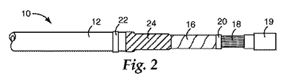
ここで図、特に図1を参照すると、内部に誘電性流体を含有した代表的な電気ケーブル10が表されている。ケーブル10は紙絶縁鉛被(「PILC」)単一導体ケーブルを代表するものであり、外側の鉛ジャケット12、カーボン充填紙又は金属化紙から形成される中間半導体層14、含油絶縁層16(代表的なケーブル10の内部では油浸紙から形成される)、及び中心導体又は導体18の群から構成される。絶縁層16の下には、半導体層がある。ケーブル10はまた、鉛ジャケット12を包囲し保護する外装合成樹脂シースを有する場合もある。
Referring now to the figures, and in particular to FIG. 1, a representative
説明の目的のため、本開示は特に、油浸ドレイニングPILCケーブルの端部において、同端部から流体が漏れ出すのを防ぎ、それによってケーブルに広範な付属品を取り付けることを可能にするための封止又は油止めの形成について記述する。しかしながら、本開示の教示は、本明細書に記述する特定のPILCケーブルとは異なる構成を有するケーブルにも等しく適用可能であることは当然である。例えば、本明細書の教示は、グリースを含浸させた高粘度油浸ノンドレイニング(MIND)ケーブルにも適用可能である。同様に、本開示の教示は、グリースなどの高粘度材料をはじめとして、油以外の流体にも等しく適用可能である。すなわち、本明細書で使用する場合、用語「PILCケーブル」は流体又は粘性材料を内部に有するあらゆるタイプのケーブルをも包含するものとして理解され、また用語「油」及び「油止め」は、ケーブルの構成において用いられるあらゆるタイプの流体又は粘性材料をも包含するものとして理解される。 For illustrative purposes, the present disclosure is particularly intended to prevent fluid from leaking out of the end of an oil-drained PILC cable, thereby allowing a wide range of accessories to be attached to the cable. Describes the formation of a seal or oil stop. However, it will be appreciated that the teachings of the present disclosure are equally applicable to cables having configurations different from the specific PILC cables described herein. For example, the teachings herein can be applied to high viscosity oil immersion non-draining (MIND) cables impregnated with grease. Similarly, the teachings of the present disclosure are equally applicable to fluids other than oil, including high viscosity materials such as grease. That is, as used herein, the term “PILC cable” is understood to encompass any type of cable having fluid or viscous material therein, and the terms “oil” and “oil stop” It is understood to encompass any type of fluid or viscous material used in the construction.
図1に示すように、ケーブル10は、油止めの取り付けに備えて、最初に鉛ジャケット12の一部(例えば28cm)が切り落とされ、これによって半導体層14が露出される。これよりわずかに小さな、半導体層14の一部(例えば22cm)が同様に除去され、含油絶縁層16が露出される。最後に更に小さな、含油絶縁層16の一部(例えば11cm)が除去され、中心導体18が露出される。絶縁層16の下の半導体層は実質的に絶縁層16と同じ長さだけ除去される。ケーブル遷移コネクタ19が中心導体18の上に取り付けられる。コネクタ19はいずれのタイプのコネクタであってもよく、ケーブル10をスプライス接続又は終端処理するのに用いられるコネクタを含むがそれに限定されない。
As shown in FIG. 1, in preparation for attaching the oil stopper, the
図2に示すように、含油絶縁層16の実施の一例において、含油絶縁層16は、この含油絶縁層16がほどけないようにする絶縁性粘着テープ片20によって所定の位置に保持される。この目的に適したテープは、本発明の譲受人である3M社により「33+Vinyl Electrical Tape」として販売されている。以下に説明するように、鉛ジャケット12の切り口の位置を示す目印とするために、第2片目のテープ22を、切り口付近(例えば1〜2cmの範囲内)の鉛ジャケット12の上に配置してもよい。テープ22としてはテープ20として用いられたと同じタイプのテープを用い得る。
As shown in FIG. 2, in one example of the implementation of the oil-containing
一実施形態による油止め形成のための更なる備えとして、ケーブル10にある種の誘電応力緩和が施される。一実施形態では、この応力緩和は、鉛ジャケット12及び半導体層14の終端部の周りに高誘電率テープ(あるいは応力制御テープ)24を巻くことによって達成される。応力制御テープ24は半導体層14を完全に覆い、かつ含油絶縁層16にわずかに(例えば1cm)重なる。この目的に適したテープは3M社より「2220 Stress Control Tape」として入手可能である。
As a further provision for oil stop formation according to one embodiment, the
ここで図3を参照すると、油止めの第1の要素はエラストマーチューブ26である。エラストマーチューブ26は、電気的に絶縁性で実質的に不透油性であり、以下により詳細に説明するように、フルオロエラストマーとエピクロロヒドリンとを含有する組成物から形成される。本明細書で使用する場合、用語「実質的に不透油性」は、ケーブル内に含まれる特定の流体に対して限定的に不透性であること及び絶対的に不透性であることの両方を包含する。限定的不透性は軍規格SC−X15111B(1984年9月27日)に既定されるように、最大許容重量増加率によって定義される。エラストマーチューブ26は典型的には押出又は型成形によって作製され、弛緩状態ではほぼ円筒状である。本明細書で使用する場合、用語「チューブ」、「チューブ状」「円筒」、又は「円筒状」等は、円形の断面を有する物体に限定されるものではなく、任意の断面の中空で細長い部材を意味する。エラストマーチューブ26は単層の要素であってもよいし、また、複合的機械的支持を提供するため又はシステムを経済的により魅力あるものにするために、他のエラストマーとともに多層構造の要素として形成されてもよい。
Referring now to FIG. 3, the first element of the oil stop is an
エラストマーチューブ26の寸法はケーブル10の寸法に応じて大幅に異なり得る。一実施形態では、エラストマーチューブ26の長さは鉛ジャケット12からコネクタ19までの長さに等しいかそれより大きい。エラストマーチューブ26の直径は(弛緩状態で)絶縁層16の直径より、典型的には1ミリメートル以上小さい。エラストマーチューブ26の弾性特性のため、ケーブル10には様々な直径を有する単一直径チューブが便利に利用され得る。もちろん、図3に示す膨張状態では、エラストマーチューブ26の直径はケーブル10の直径より大きい。エラストマーチューブ26の(弛緩状態における)厚みは、意図する用途に応じて異なり得る。
The dimensions of the
ケーブル10上への取り付けに先立って、エラストマーチューブ26は、例えば米国特許第3,515,798号の記述において公知であるような取り外し可能なコア28の上に支持される。取り外し可能なコア28は、エラストマーチューブ26を放射状に膨張した状態に維持し、このコアはまた、ほぼ円筒状であり、エラストマーチューブ26よりもわずかに長い。取り外し可能なコア28の直径は大きく異なり得、実際的に必要とされる条件は、ケーブル10の直径より大きく、この取り外し可能なコア28を除去するのに十分な隙間を提供するということだけである。取り外し可能なコア28の壁は、典型的には1ミリメートル〜5ミリメートルの範囲の厚みを有する。取り外し可能なコア28は、例えば酢酸酪酸セルロース、ポリプロピレン、ポリエチレン、又はポリ塩化ビニルのような、耐久性があって可撓性の任意の材料で構成される。一実施形態では、取り外し可能なコア28は、隣接コイル同士が分離できるように結合したらせんコイル状のストリップであり、この構造により、ストリップの端部30を強く引いて巻きをほどくことでコアを分解しエラストマーチューブ26の内部から除去することが可能となる。
Prior to mounting on the
図3に示すように、エラストマーチューブ26の一端はマーキングテープ22に隣接して保持される。取り外し可能なコア28の端部30を引くと、エラストマーチューブ26はケーブル10の周りの所定の位置へと徐々に収縮し、やがて図4に示すようにケーブル10にしっかりと弾性的に適合する。図4に示した実施形態では、エラストマーチューブ26は鉛ジャケット12と約2センチメートル(2cm)重なっており、コネクタ19とも同様の距離だけ重なっている。したがって、エラストマーチューブ26はケーブル10から流体が漏れるのを防ぐ油止めを提供するとともに、ケーブル10の内部に水が浸入するのを防ぐ。
As shown in FIG. 3, one end of the
エラストマーチューブ26は含油絶縁層16と直接接触し、含油絶縁層16に弾性的圧力を加えていることに注意すべきである。本明細書で用いる場合、「弾性的圧力」とは、取り付けられたエラストマー部材が、その下にある基材の寸法変化及びケーブルの流体の圧力が例えば熱膨張又は収縮により変化するに伴って、膨張及び収縮する能力を指す。このため、都合のよいことに、エラストマーチューブ26が円筒状及び弾性的に膨張及び収縮するにつれ、エラストマーチューブ26の変形によりケーブル10内部の流体の圧力が緩和され、ケーブル10内部の圧力が制限される。
It should be noted that the
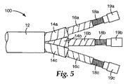
上述したように、PILCケーブルは1つを超える中心導体18を含み得る。図5を参照すると、ケーブル100は複数の導体18を有するPILCケーブルを代表するものである。ケーブル100は、3つの導体18a、18b、18c(導体18と総称する)を有するものとして表されているが、他の導体数も可能である。図1〜4を参照して上述したケーブル10と同様、ケーブル100の各導体18a、18b、18cはそれぞれ、代表的なケーブル100の内部に油浸紙によって形成された、対応する含油絶縁層16a、16b、16c(含油絶縁層16と総称する)によって包囲されており、この含油絶縁層16a、16b、16cはまた、それぞれ、カーボン充填紙又は金属化紙から形成された、対応する中間半導体層14a、14b、14c(中間半導体層14と総称する)によって包囲されている。この導体18の群(すなわち対応する絶縁層16及び半導体層14を伴った各導体18)は、単一の外装鉛ジャケット12によって包囲されてケーブル100を形成している。ケーブル100はまた、鉛ジャケット12を包囲し保護する外装合成樹脂シースを有する場合もある。
As described above, a PILC cable may include more than one
図5に示したように、ケーブル100は、油止めの取り付けに備えて、最初に鉛ジャケット12の一部が切り落とされ、これによって複数の導体18並びに関連の半導体層14及び含油層16が露出されかつ互いに分かれた状態になることができる。ケーブル100内の複数の導体18のそれぞれは、ケーブル10(図1)の導体18について上述したと同様の方法で下処理される。すなわち、半導体層14の一部が除去されることで下の含油絶縁層16が露出され、その後、これより小さな、含油絶縁層16の一部が除去されて下にある中心導線18が露出される。その後、ケーブル遷移コネクタ19a、19b、19c(コネクタ19と総称する)が中心導体18上に取り付けられる。先に述べたように、コネクタ19はいかなるタイプのコネクタであってもよく、ケーブル10をスプライス接続し又は終端処理するのに用いられるコネクタを含むがそれらに限定されない。
As shown in FIG. 5, the
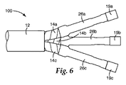
図6に示すように、下処理済みの各導体(図5に18a、18b、18cで示す)に対し、それぞれエラストマーチューブ26a、26b、26cが、図1〜4を参照して上述したと同様の方法で取り付けられるが、鉛ジャケット12及び半導体層14の終端部に高誘電率テープを巻くといった誘電応力緩和策は省略され得る。図1〜4を参照して上述したように、エラストマーチューブ26は電気的に絶縁性で実質的に不透油性であり、以下により詳細に説明するように、フルオロエラストマーとエピクロロヒドリンとを含有する組成物から形成される。一実施形態では、各エラストマーチューブ26の長さは鉛ジャケット12からコネクタ19までの長さに等しいかそれより大きい。図6に示す実施形態では、各エラストマーチューブ26はコネクタ19に約2センチメートル(2cm)重なっているが、導体18が集束する性質上、完全に鉛ジャケット12に至るまでは延在していない。一実施形態では、エラストマーチューブ26は鉛ジャケット12に可能な限り近づけて配置し得る。
As shown in FIG. 6, for each pretreated conductor (indicated by 18a, 18b, 18c in FIG. 5), the
図6に示すように、取り付け後は、各エラストマーチューブ26は対応する導体18、含油絶縁層16、及び半導体層14にしっかりと弾性的に適合する。各エラストマーチューブ26は下の含油絶縁層16と直接接触し、含油絶縁層16に弾性的圧力を加えている。
As shown in FIG. 6, after installation, each
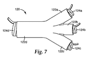
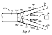
図7及び8を参照すると、ケーブル100の油止めの第2の要素が表されている。具体的には、エラストマーブーツ120が表されている。エラストマーブーツ120は、相互に連通した複数の中空エラストマー部分(又は部材)122a、122b、122c、及び122dを有する、分岐した常温収縮物品である。図7は、対応する取り外し可能なコア124a、124b、124c、及び124d上で膨張状態にある、中空のエラストマー部分122a、122b、122c、及び122dを示している。一実施形態では、エラストマーブーツ120は電気的に絶縁性である。一実施形態では、エラストマーブーツ120は不透油性である。一実施形態では、エラストマーブーツ120はフルオロエラストマーとエピクロロヒドリンとを含有する組成物から形成される。一実施形態では、エラストマーブーツ120及びエラストマーチューブ26は実質的に同一の組成物から形成される。一実施形態では、エラストマーブーツ120は半導体であって、誘電応力緩和をもたらす助けとなる。エラストマーブーツ120は典型的には型成形によって作製される。エラストマーチューブ26と同様、エラストマーブーツ120は単層の要素であってもよいし、また、複合的機械的支持を提供するため又はシステムを経済的により魅力あるものにするために、他のエラストマーとともに多層の要素として形成されてもよい。
With reference to FIGS. 7 and 8, the second element of the oil stop of the
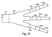
図7に示すように、エラストマーブーツ120は手袋の形に形成され、もとのままのケーブル100を受容する寸法をもつ大きな開口(部分122d)を備えるとともに、他端には数個のより小さな開口(部分122a、122b、及び122c)を有し、分かれた個々の導体18がエラストマーブーツ120から抜け出せるようになっている。小さな開口の数はケーブル100の導体18の数に対応している。
As shown in FIG. 7, the
エラストマーブーツ120(より具体的にはその部分122a、122b、122c、及び122d)は、ケーブル100及び下処理した導体18上に、エラストマーチューブ26の配置に関して上述した方法に準じて配置されてよい。具体的には、取り外し可能なコア124a、124b、124c、及び124dが除去され、エラストマーブーツ120の各部分122a、122b、122c、及び122dが所定の位置へと収縮し、図8に示すようにケーブル100にしっかりと弾性的に適合する。エラストマーチューブ26と同様に、エラストマーブーツ120の寸法も、ケーブル100及びその内部の導体18の寸法に応じて大きく異なり得る。部分122a、122b、122c、及び122dの直径は、これらの部分の収縮状態において、対応するケーブル100並びに26a、26b、及び2cの外表面に対して効果的に封止エラストマーチューブができるような寸法である。一実施形態では、図8に示すように、部分122a、122b、122c、及び122dの長さは、これらの部分の収縮状態において、部分122dがケーブル100の鉛ジャケット12に約2センチメートル(2cm)重なることができ、かつ部分122a、122b、及び122cの長さが下のエラストマーチューブ26a、26b、及び26cに約5cm〜8cm重なるに十分となるに足る長さである。当然ながら、エラストマーブーツ120の他の重なりの程度も可能であり、意図する用途によっては望ましいこともあり得る。いったんエラストマーブーツ120が所定の位置につくと、油止めは完了する。このアセンブリは信頼性の高い封止を作り出し、典型的な使用条件において、ケーブル100からのいかなる流体の脱出をも防止すると同時に、ケーブル100内への水の浸入をも防止する。
Elastomer boot 120 (more specifically,
用途によっては、エラストマーブーツ120に、エラストマーブーツ120の取り付け中又は取り付け後に空気を抜くためのニップル140(図8)を設けることによって、エラストマーブーツ120下(例えば部分122a、122b、及び122cの間の領域130)における空隙の存在、又は空隙の可能性を避け得る場合がある。
Depending on the application, the
エラストマーブーツ120が下のエラストマーチューブ26に、そして下の含油絶縁層16にも、弾性的圧力を及ぼしていることに注意すべきである。すなわち、例えば熱膨張及び収縮によって下のケーブル100の寸法が変化し、またケーブル流体の圧力が変化するに伴い、エラストマーチューブ26及びエラストマーブーツ120の両方が、膨張及び収縮する。このため、都合のよいことに、エラストマーチューブ26及びエラストマーブーツ120が円筒状及び弾性的に膨張及び収縮するにつれ、ケーブル100内部の流体の圧力が緩和され、ケーブル100内部の流体の圧力が制限される。
It should be noted that the
本明細書に記述する油止めは事実上、PILCケーブル(単芯又は多芯を問わず)の端部を合成樹脂ケーブルに転化させる。PILCケーブルはその結果、通常は押出成形による誘電体ケーブルの場合に限られている、様々なケーブル付属品の使用に対応し得る。例えば、中心導体18にラグ端子を取り付けるためにコネクタを用いてもよいし、また、ケーブルの導体18を他のケーブルの導体(図示せず)に接続するために別個のスプライスアセンブリを用いてもよい。他のケーブルは押出成形による誘電体ケーブルであってもよいし、また、本開示による油止めを同様に施したPILCケーブルであってもよい。
The oil stop described herein effectively converts the end of a PILC cable (whether single core or multicore) into a synthetic resin cable. As a result, PILC cables can accommodate the use of various cable accessories, usually limited to extruded dielectric cables. For example, a connector may be used to attach the lug terminal to the
先に言及したように、本開示は、少なくともフルオロエラストマーとエピクロロヒドリンとを含有するエラストマー組成物から形成される常温収縮物品を含む。少なくともフルオロエラストマーとエピクロロヒドリンとを含有する好適なエラストマー組成物の例は、本出願と同時係属中で譲受人を同じくする米国特許出願第11/191,838号(「常温収縮物品及び常温収縮物品を製作する方法」、2005年1月28日出願)に詳細に記述されており、その内容は全体として参照により本明細書に組み入れられる。 As mentioned above, the present disclosure includes cold shrink articles formed from an elastomer composition containing at least a fluoroelastomer and epichlorohydrin. Examples of suitable elastomeric compositions containing at least a fluoroelastomer and epichlorohydrin are described in commonly assigned US patent application Ser. No. 11 / 191,838 (“cold shrink articles and Method for making shrinkable articles ", filed Jan. 28, 2005), the contents of which are hereby incorporated by reference in their entirety.
用語「エピクロロヒドリン」は、本明細書で使用される場合、エピクロロヒドリンモノマーを含有する任意のポリマー、例えば、エピクロロヒドリンを含むフォトポリマー、コポリマー、ターポリマー及びテトラポリマー等をはじめとする、エピクロロヒドリンを含有する任意の物質を指す。用語「常温収縮」は、本明細書で使用される場合、物品(又は物品の一部分)が室温状態(例えば約20℃〜25℃)でありかつ加熱しない状態で、膨張状態から弛緩状態又はある程度の膨張状態へ向けて収縮する能力として定義される。 The term “epichlorohydrin” as used herein refers to any polymer containing an epichlorohydrin monomer, such as photopolymers, copolymers, terpolymers and tetrapolymers containing epichlorohydrin. It refers to any substance containing epichlorohydrin, including first. The term “cold shrinkage” as used herein refers to an article (or a portion of an article) that is at room temperature (eg, about 20 ° C. to 25 ° C.) and is not heated, from an expanded state to a relaxed state or to some extent. Defined as the ability to contract toward the inflated state.
エラストマーは常温収縮物品のエラストマー組成物内に含まれ、常温収縮物品が再度、弛緩状態へと常温収縮することも可能にしながら、同物品が弛緩状態から膨張状態に膨張することを可能にする。フルオロエラストマーとエピクロロヒドリンとの混合物が、本発明のエラストマー組成物として挙げられる。本発明の常温収縮物品のいくつかの実施形態は、人間の肉眼での視覚検査後に、いかなる割裂、破断又は破損をも示すことなく、膨張状態で少なくとも約150℃の温度に長時間曝され得る。 The elastomer is included in the elastomer composition of the cold-shrink article, allowing the cold-shrink article to expand from the relaxed state to the expanded state while also allowing the cold-shrink article to shrink at room temperature to the relaxed state again. A mixture of a fluoroelastomer and epichlorohydrin is mentioned as the elastomer composition of the present invention. Some embodiments of the cold-shrink article of the present invention may be exposed to a temperature of at least about 150 ° C. in an expanded state for extended periods of time after visual inspection with the human eye without exhibiting any splitting, breaking or breakage. .
特に明記しない限り、本明細書においてすべての濃度は、100重量部のゴム(phr)に対する重量部で表され、ここでゴムは、フルオロエラストマー及びエピクロロヒドリンの両方の合計重量として定義される。したがって、本明細書で使用されるとき、特定の構成要素のphrは、フルオロエラストマー及びエピクロロヒドリンの合計100重量部に対する、その構成要素の重量部を表す。 Unless otherwise stated, all concentrations herein are expressed in parts by weight relative to 100 parts by weight rubber (phr), where rubber is defined as the total weight of both fluoroelastomer and epichlorohydrin. . Thus, as used herein, phr for a particular component represents that component's parts by weight relative to 100 parts by weight of the total of the fluoroelastomer and epichlorohydrin.
広い範囲の濃度のエピクロロヒドリン及びフルオロエラストマーが、本発明のエラストマー組成物には含有され得る。例えば、いくつかの実施形態では、本発明のエラストマー組成物のフルオロエラストマーの濃度は、フルオロエラストマー及びエピクロロヒドリンの合計100重量部につき、フルオロエラストマー約10重量部〜約60重量部の範囲にわたり、エラストマー組成物のエピクロロヒドリンの濃度は、フルオロエラストマー及びエピクロロヒドリンの合計100重量部につき、エピクロロヒドリン約40重量部〜約90重量部の範囲にわたることができる。本明細書で使用するとき、エピクロロヒドリンを含有するポリマー(例えば、エピクロロヒドリンを含有するホモポリマー、コポリマー、ターポリマー、及びテトラポリマー)との関連において、エピクロロヒドリンの重量部は、エピクロロヒドリンを含有するポリマーの総重量を参照する。 A wide range of concentrations of epichlorohydrin and fluoroelastomers can be included in the elastomer compositions of the present invention. For example, in some embodiments, the concentration of the fluoroelastomer of the elastomer composition of the present invention ranges from about 10 parts by weight to about 60 parts by weight of fluoroelastomer per 100 parts by weight of the total fluoroelastomer and epichlorohydrin. The concentration of epichlorohydrin in the elastomeric composition can range from about 40 parts by weight to about 90 parts by weight of epichlorohydrin per 100 parts by weight total of the fluoroelastomer and epichlorohydrin. As used herein, parts by weight of epichlorohydrin in the context of polymers containing epichlorohydrin (eg, homopolymers, copolymers, terpolymers, and tetrapolymers containing epichlorohydrin). Refers to the total weight of the polymer containing epichlorohydrin.
(エラストマー組成物から形成された)常温収縮物品の高温での割裂及び破断に対する特性を高めるため、強化充填材料が任意で、本発明のエラストマー組成物中に含有され得る。好適な充填材料の例としては、シリカ系強化充填材、強化等級カーボンブラック、フッ素樹脂、粘土、及びこれらいずれの材料の任意の割合での任意の組み合わせが挙げられる。好適な充填材の例は先に言及した米国特許出願第11/191,838号に詳細に記述されている。本明細書で用いる場合、用語「シリカ系強化充填材」は式SiO2(例えば純シリカ)のすべての化合物;化合物の総重量を基準にして少なくとも約10重量パーセントのSiO2及び/又はSiO2誘導体を含むすべての組成物;すべてのケイ酸塩;並びにこれらの任意のものの任意の比率による任意の組み合わせを含むものとして定義される。ここで使用されている語句「強化等級カーボンブラック」は、約65m2/gの平均表面積に相当する約40nm未満の平均粒径を有する任意のカーボンブラックを含む。 Reinforcing filler materials can optionally be included in the elastomeric compositions of the present invention to enhance the properties of cold-shrinked articles (formed from elastomeric compositions) against high temperature splitting and breaking. Examples of suitable filler materials include silica-based reinforcing fillers, reinforcing grade carbon black, fluororesin, clay, and any combination of any of these materials in any proportion. Examples of suitable fillers are described in detail in the previously referenced US patent application Ser. No. 11 / 191,838. As used herein, the term “silica-based reinforcing filler” refers to any compound of formula SiO 2 (eg, pure silica); at least about 10 weight percent SiO 2 and / or SiO 2 based on the total weight of the compound. All compositions including derivatives; all silicates; and any combination of any of these in any ratio are defined. As used herein, the phrase “reinforced grade carbon black” includes any carbon black having an average particle size of less than about 40 nm, corresponding to an average surface area of about 65 m 2 / g.
エラストマー組成物はその後、任意の適切な方法、例えば押出又は型成形によって、常温収縮物品へと形成され得る。実施形態によっては、常温収縮物品のエラストマー組成物は、エラストマー組成物の物理的特性に影響を与えるべく、硬化、オートクレーブ処理、又は放射線処理される。好適な硬化、オートクレーブ処理、及び放射線処理の方法は、先に言及した米国特許出願第11/191,838号に詳細に記述されている。 The elastomeric composition can then be formed into a cold shrink article by any suitable method, such as extrusion or molding. In some embodiments, the elastomer composition of the cold-shrink article is cured, autoclaved, or radiation treated to affect the physical properties of the elastomer composition. Suitable curing, autoclaving and radiation treatment methods are described in detail in the above-referenced US patent application Ser. No. 11 / 191,838.
本発明のエラストマー組成物は、当該技術分野において公知のいかなる形状又は幾何学的外形の常温収縮物品にも形成され得る。常温収縮物品のいくつかの限定的例には、管、板、及び複数分岐構造体(すなわち、複数の入口及び/又は出口を有する手袋様の構造体)が挙げられる。 The elastomeric composition of the present invention can be formed into cold shrink articles of any shape or geometric shape known in the art. Some limited examples of cold shrink articles include tubes, plates, and multi-branched structures (ie, glove-like structures with multiple inlets and / or outlets).
(本発明のエラストマー組成物から形成された)本発明の常温収縮物品は、様々な環境条件(例えば、室温又は150℃)の下で、様々な有利な機械的性質を様々な組み合わせで示し得る。いくつかの実施形態では、管及び板等の本発明の常温収縮物品は、この文書の性質分析及び特性解析手段の項の手順にしたがって試験される際に、室温で少なくとも約450%の破断伸び及び/又は150℃で少なくとも約250%の破断伸びを示し得る。管及び板等の本発明の常温収縮物品のいくつかの実施形態は、性質分析及び特性解析手段の項の手順に従って試験される際に、100℃で約35%未満の永久ひずみ率を示し得る。更に、本発明の組成物から形成される管及び板のいくつかの実施形態は、100℃で約25%未満の永久ひずみ率を示し得る。いくつかの実施形態では、本発明の組成物から形成される板は、100℃で約20%未満の永久ひずみ率を示し得る。 Cold shrink articles of the present invention (formed from the elastomer composition of the present invention) can exhibit various advantageous mechanical properties in various combinations under various environmental conditions (eg, room temperature or 150 ° C.). . In some embodiments, cold-shrink articles of the present invention, such as tubes and plates, when tested according to the procedures in the characterization and characterization means section of this document, at least about 450% elongation at break at room temperature. And / or exhibit an elongation at break of at least about 250% at 150 ° C. Some embodiments of the cold shrink article of the present invention, such as tubes and plates, may exhibit a permanent set rate of less than about 35% at 100 ° C. when tested according to the procedures in the Property Analysis and Characterization Tools section. . Furthermore, some embodiments of tubes and plates formed from the compositions of the present invention may exhibit a permanent set rate of less than about 25% at 100 ° C. In some embodiments, a plate formed from the composition of the present invention may exhibit a permanent set rate of less than about 20% at 100 ° C.
本発明の常温収縮物品の様々な実施形態は、高温での破断又は割裂に耐える。例えば、本発明の常温収縮物品のいくつかの実施形態は、約150℃の高温で膨張状態に長期間(例えば放射状に200%膨張した状態で7日間)維持された際に、破断に耐える。 Various embodiments of the cold shrink article of the present invention resist high temperature breaks or splits. For example, some embodiments of the cold shrink article of the present invention resist rupture when maintained in an expanded state at an elevated temperature of about 150 ° C. for an extended period of time (eg, 7 days in a radially expanded state of 200%).
本発明の常温収縮物品の様々な実施形態は、例えばディーゼル燃料及び油圧油等の物質に対して化学的耐性を示す。本発明の常温収縮物品のいくつかの実施形態は、ディーゼル燃料に約49℃で24時間浸された際に約25%未満の重量増加率、及び/又は油圧油に約71℃で24時間浸された際に約10%未満の重量増加率を示す。 Various embodiments of the cold shrink article of the present invention exhibit chemical resistance to materials such as diesel fuel and hydraulic oil. Some embodiments of the cold shrink article of the present invention have a weight gain of less than about 25% when soaked in diesel fuel at about 49 ° C. for 24 hours and / or soak in hydraulic oil at about 71 ° C. for 24 hours. Show a weight gain of less than about 10%.
実施形態としては例えばケーブル用圧力抑制エンクロージャを挙げることができる。図9〜10を参照すると、第1のケーブル12は、導体及び導体を包囲する含油層を含み得る。第2のケーブル55は導体を含み得る。スプライス50が第1のケーブル12の導体を第2のケーブル55の導体に接続し得る。圧力抑制スリーブ60がスプライス50並びに第1のケーブル及び第2のケーブル55の導体を被覆し得る。圧力抑制スリーブ60は、例えば多数の撚り合わされたストランドを含んでもよいし、より具体的には多数の編組ワイヤを含んでもよい。
As an embodiment, for example, a pressure suppression enclosure for cables can be cited. With reference to FIGS. 9-10, the
圧力抑制スリーブ60をスプライス50並びに第1及び第2のケーブル55の部分の周りに締め付けるために、数個の締結具が圧力抑制スリーブ60上の数箇所に取り付けられ得る。例えば、圧力抑制スリーブ60上、スプライス50の端部に対して放射状に合わせた位置に、数個の締結具66、68を取り付けてもよい。また、例えば、圧力抑制スリーブ60上、スプライス50からいずれかの側に離れた位置に、数個の締結具62、64を取り付けてもよい。締結具は締め付けることができるものであれば、例えばクランプ構造、ワイヤの巻き付けすなわちワイヤラップ、テープ材、ケーブルタイをはじめとするいずれの構造をも含み得る。
Several fasteners may be attached at several locations on the
実施形態は、第1のケーブル12の含油層の一部分を被覆する、電気的に絶縁性で実質的に不透油性のエラストマーチューブ26を含み得る。エラストマーチューブ26の実施形態は、例えば、実質的に第1のケーブル12の終端部付近に配置することができ、この終端部付近において、第1のケーブル12の導体が、部分的に露出した中心導体を含み得、第1のケーブル12の含油層が、部分的に露出し導体を包囲する油浸電気的絶縁紙層を含み得る。第1のケーブル12はまた、例えば、紙層を包囲する部分的に露出した半導体層及び半導体層を包囲する鉛ジャケットを含むことができ、エラストマーチューブ26が半導体及び紙層の露出した部分に接触し、かつその部分を包囲する。圧力抑制スリーブ60上、エラストマーチューブ26の一部分に対して放射状に合わせた位置に、少なくとも1つの締結具70、72を取り付けることもできる。例えば、圧力抑制スリーブ60上、エラストマーチューブ26の端部に対して放射状に合わせた位置に、締結具70、72を取り付けることもできる。
Embodiments may include an electrically insulating and substantially oil-impervious
エラストマーチューブ26は、例えば、フルオロエラストマーとエピクロロヒドリンとを含有する組成物であってよい。エラストマーチューブ26の実施形態は、例えば、フルオロエラストマー及びエピクロロヒドリン100重量部について約10重量部〜約60重量部の範囲のフルオロエラストマーを含有し得る。エラストマーチューブ26の実施形態は、例えば、フルオロエラストマー及びエピクロロヒドリンの合計100重量部について約40重量部〜約90重量部の範囲のエピクロロヒドリンを含有し得る。
The
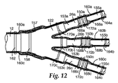
別の実施形態は、例えば、他のケーブル用圧力抑制エンクロージャを含み得る。ここで図12を参照すると、ケーブルは、分岐して一連の第1のケーブル153a、153b、153cを形成する単一の主ケーブル12を含み得る。ここで第1のケーブルは、導体と、この導体を包囲する含油層とを有する。一連の第2のケーブル155a、155b、155cはそれぞれ導体を含み得る。数個のスプライス150a、150b、150cが、一連の第1のケーブル153a、153b、153cの各ケーブルの導体を一連の第2のケーブル155a、155b、155cの各ケーブルの導体に接続し得る。電気的に絶縁性のエラストマーブーツ122が主ケーブル12の一部分、及び一連の第1のケーブル153a、153b、153cの一部分を被覆し得る。エラストマーブーツ122は手袋様のボディを含み得、このボディは、その手袋様ボディの第1の端部に単一の開口、同手袋様ボディの第2の端部に数個の開口を有し、単一の開口が主ケーブル12を受容し、数個の開口のそれぞれが一連の第1のケーブルの各ケーブル153a、153b、153cを受容し得る。ブーツ122の別の実施形態はまた、半導体であり得る。
Other embodiments may include, for example, other cable pressure suppression enclosures. Referring now to FIG. 12, the cable may include a single
エラストマーブーツ122は、例えば、フルオロエラストマーとエピクロロヒドリンとを含有する組成物であってよい。エラストマーブーツ122の実施形態は、例えば、フルオロエラストマー及びエピクロロヒドリン100重量部について約10重量部〜約60重量部の範囲のフルオロエラストマーを含有し得る。エラストマーブーツ122の実施形態は、例えば、フルオロエラストマー及びエピクロロヒドリンの合計100重量部について約40重量部〜約90重量部の範囲のエピクロロヒドリンを含有し得る。
The
圧力抑制ボディ157が主ケーブル12及びエラストマーブーツ122を被覆し得る。圧力抑制ボディ157は、その圧力抑制ボディ157の一端に単一の開口、同圧力抑制ボディ157の他端に数個の開口を有し得、単一の開口が主ケーブル12を受容し、数個の開口のそれぞれが一連の第1のケーブル153a、153b、153cの各ケーブルを受容し得る。複数の圧力抑制スリーブ160a、160b、160cが含まれ得、各圧力抑制スリーブ160a、160b、160cは、各スプライス150a、150b、150c並びに一連の第1のケーブル153a、153b、153cの各ケーブルの導体及び一連の第2のケーブル155a、155b、155cの各ケーブルの導体を被覆し得る。圧力抑制ボディ157及び各圧力抑制スリーブ160a、160b、160cは、例えば多数の撚り合わされたストランドを含んでもよいし、より具体的には多数の編組ワイヤを含んでもよい。
A
圧力抑制ボディ157をエラストマーブーツ122の周りに締め付けるため、また、各圧力抑制スリーブ160a、160b、160cを各スプライス150a、150b、150c並びに一連の第1のケーブル153a、153b、153c及び一連の第2のケーブル155a、155b、155cの各ケーブルの一部分の周りに締め付けるために、数個の締結具が、圧力抑制ボディ157及び圧力抑制スリーブ160a、160b、160cのそれぞれの上の数箇所に取り付けられ得る。例えば、圧力抑制ボディ157上、主ケーブル12の一部分に対して放射状に合わせた位置に、少なくとも1つの締結具158を取り付けることができる。また、例えば、各圧力抑制スリーブ160a、160b、160c上、スプライス150a、150b、150cの末端部分に対して放射状に合わせた位置に、多数の締結具166a、166b、166c、168a、168b、168cを取り付けることができる。加えて、例えば、各圧力抑制スリーブ160a、160b、160c上、スプライス150からいずれかの側に離れた位置に多数の締結具162、164a、164b、164cも取り付けることもできる。このようにして、例えば、圧力抑制スリーブ160a、160b、160cのすべてを一括した周りの、主ケーブル12に対して放射状に合わせた位置に、単一のI締結具162を取り付け、各圧力抑制スリーブ160a、160b、160cの他端においては、各圧力抑制スリーブ160a、160b、160cの周りに、締結具164a、164b、164cを取り付けることができる。
For tightening the
実施形態は多数の電気的に絶縁性で実質的に不透油性のエラストマーチューブ26a、26b、26cを含み得る。各エラストマーチューブ26a、26b、26cは、例えば、一連の第1のケーブル153a、153b、153cの各ケーブルの含油層の一部分を被覆し得る。また、例えば、各エラストマーチューブ26a、26b、26cは、実質的に、一連の第1のケーブル153a、153b、153cの各ケーブルの終端部付近に配置することができ、この終端部付近において、一連の第1のケーブル153a、153b、153cの各ケーブルの各導体が、部分的に露出した中心導体を含み得、一連の第1のケーブル153a、153b、153cの各ケーブルの含油層が、導体を包囲する部分的に露出した油浸電気的絶縁紙層を含み得る。一連の第1のケーブル153a、153b、153cの各ケーブルはまた、例えば、紙層を包囲する部分的に露出した半導体層及びこの半導体層を包囲する鉛ジャケットを含むことができ、各エラストマーチューブ26a、26b、26cが各半導体及び紙層の露出した部分に接触し、かつその部分を包囲する。各圧力抑制スリーブ160a、160b、160c上、エラストマーチューブ26a、26b、26cの一部分に対して放射状に合わせた位置に、少なくとも1つの締結具170a、170b、170c、172a、172b、172cを取り付け得る。例えば、各圧力抑制スリーブ160a、160b、160c上、エラストマーチューブ26a、26b、26cの末端部分に対して放射状に合わせた位置に、締結具170a、170b、170c、172a、172b、172cを取り付けることができる。
Embodiments can include a number of electrically insulating and substantially oil-impermeable
エラストマーチューブ26a、26b、26cは、例えば、フルオロエラストマーとエピクロロヒドリンとを含有する組成物であってよい。エラストマーチューブ26a、26b、26cの実施形態は、例えば、フルオロエラストマー及びエピクロロヒドリン100重量部について約10重量部〜約60重量部の範囲のフルオロエラストマーを含有し得る。エラストマーチューブ26a、26b、26cの実施形態は、例えば、フルオロエラストマー及びエピクロロヒドリンの合計100重量部について約40重量部〜約90重量部の範囲のエピクロロヒドリンを含有し得る。
The
上述の詳細な説明は、多数の具体的な詳細を解説の目的で含んでいるが、その詳細に対する多数の変形例、変更例、置換例、及び修正例が、請求する本発明の範囲に含まれることは、いずれの当業者にも理解されよう。したがって詳細な説明に記載される本発明は、請求する発明にいかなる限定も課すことなく説明されているものである。例えば、搭載された、接続された、取り付けられた、接合された、結合されたなどの用語へのいかなる言及も、間接的に、直接的に、及び/又は一体的に達成されているこのような搭載、接続、取り付け、接合、結合などを含むように、幅広く解釈されるべきである。本発明の適切な範囲は、以下の特許請求の範囲及びその適当な法的等価物によって定められるべきである。 Although the foregoing detailed description includes numerous specific details for purposes of illustration, numerous variations, modifications, substitutions, and modifications to the details are within the scope of the claimed invention. It will be understood by any person skilled in the art. Accordingly, the invention described in the detailed description is set forth without imposing any limitations on the claimed invention. For example, any reference to the terms mounted, connected, attached, joined, joined, etc. is accomplished indirectly, directly, and / or integrally. Should be construed broadly to include such mounting, connecting, mounting, joining, bonding, etc. The proper scope of the invention should be determined by the following claims and their appropriate legal equivalents.
Claims (20)
導体を含む第2のケーブルと、
前記第1のケーブルの前記導体を前記第2のケーブルの前記導体に接続するスプライスと、
前記スプライス並びに前記第1及び第2のケーブルの前記導体を被覆する圧力抑制スリーブと、
前記圧力抑制スリーブ上の複数箇所に取り付けられ、前記圧力抑制スリーブを前記スプライス並びに前記第1及び第2のケーブルの一部分の周りに締め付ける、複数の締結具と、を含む装置。 A first cable including a conductor and an oil-impregnated layer surrounding the conductor;
A second cable including a conductor;
A splice connecting the conductor of the first cable to the conductor of the second cable;
A pressure restraining sleeve covering the splice and the conductors of the first and second cables;
A plurality of fasteners attached at a plurality of locations on the pressure suppression sleeve and tightening the pressure suppression sleeve around the splice and a portion of the first and second cables.
それぞれ導体を含む一連の第2のケーブルと、
前記一連の第1のケーブルの各ケーブルの導体を前記一連の第2のケーブルの各ケーブルの導体に接続する複数のスプライスと、
手袋様のボディを含むエラストマーブーツで、前記手袋様ボディの第1の端部に単一の開口、前記手袋様ボディの第2の端部に複数の開口を有し、前記単一の開口が主ケーブルを受容し、前記複数の開口のそれぞれが前記一連の第1のケーブルの各ケーブルを受容し、前記主ケーブルの一部分並びに前記一連の第1のケーブルの一部分を被覆する、絶縁性のエラストマーブーツと、
前記主ケーブル及びエラストマーブーツを被覆する圧力抑制ボディであって、前記圧力抑制ボディの一端に単一の開口、前記圧力抑制ボディの他端に複数の開口を有し、前記単一の開口が主ケーブルを受容し、前記複数の開口のそれぞれが前記一連の第1のケーブルの各ケーブルを受容する、圧力抑制ボディと、
複数の圧力抑制スリーブであって、各圧力抑制スリーブが、各スプライス並びに前記一連の第1のケーブルの各ケーブルの前記導体及び前記一連の第2のケーブルの各ケーブルの前記導体を被覆する、圧力抑制スリーブと、
前記圧力抑制ボディを前記エラストマーブーツの周りに締め付けるため、また前記圧力抑制スリーブのそれぞれを各スプライス並びに前記一連の第1のケーブル及び前記一連の第2のケーブルの各ケーブルの一部分の周りに締め付けるために、前記圧力抑制ボディ及び前記圧力抑制スリーブのそれぞれの上の数箇所に取り付けられた、複数の締結具と、を含む装置。 A cable comprising a single main cable that branches to form a series of first cables each comprising a conductor and an oil-impregnated layer surrounding the conductor;
A series of second cables each including a conductor;
A plurality of splices connecting the cable conductors of the series of first cables to the cable conductors of the series of second cables;
An elastomeric boot including a glove-like body having a single opening at a first end of the glove-like body and a plurality of openings at a second end of the glove-like body, wherein the single opening is Insulating elastomer that receives a main cable, each of the plurality of openings receives each cable of the series of first cables and covers a portion of the main cable as well as a portion of the series of first cables. Boots,
A pressure suppression body covering the main cable and the elastomer boot, the pressure suppression body having a single opening at one end and a plurality of openings at the other end of the pressure suppression body, the single opening being a main opening A pressure suppression body that receives a cable, and wherein each of the plurality of openings receives each cable of the series of first cables;
A plurality of pressure restraining sleeves, each pressure restraining sleeve covering each splice and the conductor of each cable of the series of first cables and the conductor of each cable of the series of second cables. A restraining sleeve;
To clamp the pressure suppression body around the elastomeric boot and to clamp each of the pressure suppression sleeves around each splice and a portion of each cable of the series of first cables and the series of second cables. And a plurality of fasteners attached to several locations on each of the pressure suppression body and the pressure suppression sleeve.
Applications Claiming Priority (2)
| Application Number | Priority Date | Filing Date | Title |
|---|---|---|---|
| US11/852,522 US7973241B2 (en) | 2007-09-10 | 2007-09-10 | Pressure restraining enclosure for cables |
| PCT/US2008/073275 WO2009035814A2 (en) | 2007-09-10 | 2008-08-15 | Pressure restraining enclosure for cables |
Publications (2)
| Publication Number | Publication Date |
|---|---|
| JP2010539865A true JP2010539865A (en) | 2010-12-16 |
| JP2010539865A5 JP2010539865A5 (en) | 2011-09-22 |
Family
ID=40430622
Family Applications (1)
| Application Number | Title | Priority Date | Filing Date |
|---|---|---|---|
| JP2010524084A Ceased JP2010539865A (en) | 2007-09-10 | 2008-08-15 | Pressure suppression enclosure for cables |
Country Status (11)
| Country | Link |
|---|---|
| US (1) | US7973241B2 (en) |
| EP (1) | EP2195898A4 (en) |
| JP (1) | JP2010539865A (en) |
| KR (1) | KR20100071059A (en) |
| CN (1) | CN101803135A (en) |
| BR (1) | BRPI0815512A2 (en) |
| CA (1) | CA2698110A1 (en) |
| MX (1) | MX2010002472A (en) |
| RU (1) | RU2456729C2 (en) |
| TW (1) | TW200926550A (en) |
| WO (1) | WO2009035814A2 (en) |
Families Citing this family (26)
| Publication number | Priority date | Publication date | Assignee | Title |
|---|---|---|---|---|
| US7635813B2 (en) * | 2007-09-10 | 2009-12-22 | 3M Innovative Properties Company | Article and method for sealing fluid-containing cables |
| US8655006B2 (en) * | 2010-01-25 | 2014-02-18 | Apple Inc. | Multi-segment cable structures |
| CN103109221B (en) | 2010-09-21 | 2015-11-25 | 胡贝尔和茹纳股份公司 | The cable branch assembly of environmental sealing |
| EP2647095B1 (en) * | 2010-11-29 | 2014-08-27 | 3M Innovative Properties Company | Strain relief device |
| CN102176353B (en) * | 2011-03-16 | 2012-05-30 | 江苏长峰电缆有限公司 | Connecting method for detachable conductor connector |
| US8513543B1 (en) * | 2012-02-21 | 2013-08-20 | Asia Tai Technology Co., Ltd. | Water-proofing cable connector |
| WO2014158369A1 (en) * | 2013-03-29 | 2014-10-02 | 3M Innovative Properties Company | Modular breakout device for optical and electrical connections |
| CN104143795B (en) * | 2013-05-06 | 2017-09-15 | 泰科电子(上海)有限公司 | Cold-contraction type terminal is arranged on to method and cold-contraction type terminal assembly on power cable |
| US9438019B2 (en) | 2014-03-25 | 2016-09-06 | Henry J. Plathe | Multi-hub electrical fitting |
| US9853394B2 (en) | 2014-05-02 | 2017-12-26 | Itt Manufacturing Enterprises, Llc | Pressure-blocking feedthru with pressure-balanced cable terminations |
| USD755728S1 (en) | 2014-10-24 | 2016-05-10 | Bridgeport Fittings, Inc. | Metal clad/armored clad electrical cable to electrical conduit transition fitting housing |
| US9252577B1 (en) | 2014-10-24 | 2016-02-02 | Bridgeport Fittings, Inc. | Electrical transition fitting |
| USD755729S1 (en) | 2014-10-24 | 2016-05-10 | Bridgeport Fittings, Inc. | Metal clad/armored clad electrical cable to electrical enclosure electrical transition fitting housing |
| USD750570S1 (en) | 2014-10-24 | 2016-03-01 | Bridgeport Fittings, Inc. | Metal clad/armored clad electrical cable to electrical conduit transition fitting housing |
| USD751043S1 (en) | 2014-10-24 | 2016-03-08 | Bridgeport Fittings, Inc. | Metal clad/armored clad electrical cable to electrical enclosure electrical transition fitting housing |
| US9793029B2 (en) | 2015-01-21 | 2017-10-17 | Itt Manufacturing Enterprises Llc | Flexible, pressure-balanced cable assembly |
| CN105552793A (en) * | 2015-12-25 | 2016-05-04 | 深圳市沃尔核材股份有限公司 | Method for protecting wiring harness, wiring harness protective jacket and wiring harness system |
| USD822610S1 (en) * | 2016-11-04 | 2018-07-10 | Molex, Llc | Connector |
| USD821979S1 (en) | 2016-11-04 | 2018-07-03 | Molex, Llc | Connector |
| USD866473S1 (en) * | 2016-11-04 | 2019-11-12 | Molex, Llc | Connector |
| JP6743718B2 (en) * | 2017-01-31 | 2020-08-19 | 日立金属株式会社 | Cable waterproof structure, wire harness, and method for manufacturing wire harness |
| US9843113B1 (en) | 2017-04-06 | 2017-12-12 | Itt Manufacturing Enterprises Llc | Crimpless electrical connectors |
| US10276969B2 (en) | 2017-04-20 | 2019-04-30 | Itt Manufacturing Enterprises Llc | Connector with sealing boot and moveable shuttle |
| US9941622B1 (en) | 2017-04-20 | 2018-04-10 | Itt Manufacturing Enterprises Llc | Connector with sealing boot and moveable shuttle |
| EP3859916A1 (en) * | 2020-01-28 | 2021-08-04 | Aptiv Technologies Limited | Cable termination and method of manufacture |
| DE102020004613A1 (en) * | 2020-07-29 | 2022-02-03 | Sumitomo Wiring Systems, Ltd. | SPLICED CABLE, PARTICULARLY SPLICED HIGH VOLTAGE CABLE, AND METHOD OF SPLICING A CABLE, PARTICULARLY A HIGH VOLTAGE CABLE |
Citations (2)
| Publication number | Priority date | Publication date | Assignee | Title |
|---|---|---|---|---|
| JPH06502061A (en) * | 1990-10-25 | 1994-03-03 | ミネソタ マイニング アンド マニュファクチャリング カンパニー | Transition joint for oil-filled cable |
| JPH08280128A (en) * | 1995-04-05 | 1996-10-22 | Kinki Denki Kk | Straight sleeve cover |
Family Cites Families (42)
| Publication number | Priority date | Publication date | Assignee | Title |
|---|---|---|---|---|
| US2195933A (en) * | 1936-09-24 | 1940-04-02 | American Steel & Wire Co | Spliced cable joint |
| US2714715A (en) * | 1953-04-20 | 1955-08-02 | Charles A Manier | Oil level indicator |
| US3515798A (en) | 1968-12-06 | 1970-06-02 | Minnesota Mining & Mfg | Elastic cover and removable cone assembly |
| US3886669A (en) * | 1974-10-31 | 1975-06-03 | Thurman A Pelsue | Air dryer jacket for underground electrical cables |
| US4110550A (en) | 1976-11-01 | 1978-08-29 | Amerace Corporation | Electrical connector with adaptor for paper-insulated, lead-jacketed electrical cables and method |
| JPS5946539B2 (en) | 1977-12-30 | 1984-11-13 | ダイキン工業株式会社 | Elastomer composition |
| JPS606238B2 (en) | 1981-01-30 | 1985-02-16 | 豊田合成株式会社 | rubber laminate |
| SU1024480A1 (en) | 1981-10-08 | 1983-06-23 | Предприятие П/Я Г-4913 | Vulcanizable rubber stock |
| US4645801A (en) | 1982-09-15 | 1987-02-24 | The Bf Goodrich Company | Epihalohydrin polymers |
| US4589939A (en) * | 1984-02-17 | 1986-05-20 | Raychem Corporation | Insulating multiple-conductor cables using coated insert means |
| JPS6284153A (en) | 1985-10-09 | 1987-04-17 | Sumitomo Chem Co Ltd | Curing rubber composition |
| DE3536250A1 (en) * | 1985-10-11 | 1987-04-16 | Minnesota Mining & Mfg | CABLE TERMINAL FOR PAPER INSULATED THREE-WIRE MEDIUM VOLTAGE CABLES |
| JPH07113076B2 (en) | 1986-09-24 | 1995-12-06 | 日本ゼオン株式会社 | Oil resistant rubber mixture |
| JPH01159245A (en) | 1987-12-16 | 1989-06-22 | Tokai Rubber Ind Ltd | Rubber hose |
| DE3812398C2 (en) * | 1988-04-14 | 1997-04-10 | Minnesota Mining & Mfg | Sheath made of plastic film material for a cable end closure, a cable connection or another section of an electrical cable that has been freed from the cable sheath |
| JP2594329B2 (en) | 1988-07-15 | 1997-03-26 | 電気化学工業株式会社 | Low-gloss fluororesin-based outdoor film or sheet and method for producing the same |
| US5059648A (en) | 1988-10-27 | 1991-10-22 | Nissin Chemical Industry Co., Ltd. | Rubber composition |
| US5408047A (en) * | 1990-10-25 | 1995-04-18 | Minnesota Mining And Manufacturing Company | Transition joint for oil-filled cables |
| KR0121579Y1 (en) * | 1995-01-12 | 1999-05-15 | 김봉주 | Centering junction device for high voltage cables |
| US6015629A (en) | 1995-09-06 | 2000-01-18 | 3M Innovative Properties Company | Stress control for termination of a high voltage cable |
| US6340794B1 (en) * | 1995-09-06 | 2002-01-22 | Minnesota Mining And Manufacturing Company | Stress control for termination of a high voltage cable |
| CA2228475C (en) | 1995-09-06 | 2008-10-14 | Minnesota Mining And Manufacturing Company | Epihalohydrin electrical stress controlling material |
| EP0780949B1 (en) * | 1995-12-23 | 2000-09-20 | Minnesota Mining And Manufacturing Company | Universal cable adapter, cable joint using the adapter and method of making the same |
| US5714715A (en) | 1996-01-22 | 1998-02-03 | Minnesota Mining And Manufacturing Company | Cable end seal for oil-filled cables |
| US6114452A (en) | 1996-11-25 | 2000-09-05 | E. I. Du Pont De Nemours And Company | Perfluoroelastomer composition having excellent heat stability |
| ES2202420T3 (en) | 1996-11-29 | 2004-04-01 | Nexans | COLD RETRACTABLE PROTECTION ELEMENT FOR CABLE PACKING. |
| EP1082796A1 (en) * | 1998-05-27 | 2001-03-14 | Utilx Corporation | Cable fluid injection sleeve |
| EP0967706A1 (en) | 1998-06-26 | 1999-12-29 | Alcatel | Joint between two electrical cables and protection element therefore |
| US6103975A (en) * | 1998-06-29 | 2000-08-15 | 3M Innovative Properties Company | Pre-assembled electrical splice component |
| EP1167441B1 (en) | 2000-06-29 | 2015-07-29 | 3M Innovative Properties Company | Fluoroelastomer composition comprising a mineral oil |
| JP3705345B2 (en) | 2000-08-31 | 2005-10-12 | 信越化学工業株式会社 | Fluorosilicone rubber composition |
| JP2002317885A (en) | 2001-04-19 | 2002-10-31 | Tokai Rubber Ind Ltd | Metal composite hose, and method for manufacturing the same |
| US6852782B2 (en) | 2003-04-25 | 2005-02-08 | Milliken & Company | Antimicrobial articles and compositions made from non-silicone vulcanized rubber |
| US6838512B2 (en) | 2003-06-05 | 2005-01-04 | 3M Innovative Properties Company | Cold shrink fluoroelastomeric article |
| US20050215661A1 (en) | 2004-03-23 | 2005-09-29 | 3M Innovative Properties Company | NBC-resistant composition |
| US20050277731A1 (en) | 2004-06-11 | 2005-12-15 | Shin-Etsu Chemical Co., Ltd. | Curable perfluoropolyether compositions and rubber or gel articles comprising the same |
| US7396499B2 (en) | 2004-09-28 | 2008-07-08 | Thomas E Frankel | Multiple layered membrane with fluorine containing polymer layer |
| RU2284620C1 (en) * | 2005-05-20 | 2006-09-27 | Закрытое акционерное общество "Подольский завод электромонтажных изделий" (ЗАО "ПЗЭМИ") | Cable junction box and method for its installation and wiring |
| US7553894B2 (en) | 2005-07-28 | 2009-06-30 | 3M Innovative Properties Company | Cold-shrink article and method of making cold-shrink article |
| KR100777062B1 (en) * | 2006-09-11 | 2007-11-16 | 주식회사 평일 | Connector for cables having different diameter |
| US7511222B2 (en) | 2006-12-11 | 2009-03-31 | 3M Innovative Properties Company | Cold shrink article and method of using cold shrink article |
| US7635813B2 (en) * | 2007-09-10 | 2009-12-22 | 3M Innovative Properties Company | Article and method for sealing fluid-containing cables |
-
2007
- 2007-09-10 US US11/852,522 patent/US7973241B2/en not_active Expired - Fee Related
-
2008
- 2008-08-15 EP EP08797958A patent/EP2195898A4/en not_active Withdrawn
- 2008-08-15 CA CA2698110A patent/CA2698110A1/en not_active Abandoned
- 2008-08-15 CN CN200880106466A patent/CN101803135A/en active Pending
- 2008-08-15 WO PCT/US2008/073275 patent/WO2009035814A2/en active Application Filing
- 2008-08-15 JP JP2010524084A patent/JP2010539865A/en not_active Ceased
- 2008-08-15 BR BRPI0815512-7A2A patent/BRPI0815512A2/en not_active IP Right Cessation
- 2008-08-15 MX MX2010002472A patent/MX2010002472A/en active IP Right Grant
- 2008-08-15 KR KR1020107007715A patent/KR20100071059A/en not_active Application Discontinuation
- 2008-08-15 RU RU2010106228/07A patent/RU2456729C2/en not_active IP Right Cessation
- 2008-09-01 TW TW097133499A patent/TW200926550A/en unknown
Patent Citations (2)
| Publication number | Priority date | Publication date | Assignee | Title |
|---|---|---|---|---|
| JPH06502061A (en) * | 1990-10-25 | 1994-03-03 | ミネソタ マイニング アンド マニュファクチャリング カンパニー | Transition joint for oil-filled cable |
| JPH08280128A (en) * | 1995-04-05 | 1996-10-22 | Kinki Denki Kk | Straight sleeve cover |
Also Published As
| Publication number | Publication date |
|---|---|
| BRPI0815512A2 (en) | 2015-02-10 |
| US7973241B2 (en) | 2011-07-05 |
| US20090065237A1 (en) | 2009-03-12 |
| CA2698110A1 (en) | 2009-03-19 |
| WO2009035814A3 (en) | 2009-05-22 |
| MX2010002472A (en) | 2010-03-26 |
| EP2195898A4 (en) | 2011-10-05 |
| RU2010106228A (en) | 2011-10-20 |
| KR20100071059A (en) | 2010-06-28 |
| RU2456729C2 (en) | 2012-07-20 |
| EP2195898A2 (en) | 2010-06-16 |
| TW200926550A (en) | 2009-06-16 |
| WO2009035814A2 (en) | 2009-03-19 |
| CN101803135A (en) | 2010-08-11 |
Similar Documents
| Publication | Publication Date | Title |
|---|---|---|
| JP2010539865A (en) | Pressure suppression enclosure for cables | |
| JP2010539867A (en) | Oil-impregnated cable sealing article and method | |
| RU2396659C1 (en) | Cold shrinkage item and method of using cold shrinkage item | |
| CN101606297B (en) | Protection device for power cables with impregnated-paper-based insulation | |
| US7883356B2 (en) | Jacket sleeve with grippable tabs for a cable connector | |
| US10373738B2 (en) | Insulated wire construction with liner | |
| US5714715A (en) | Cable end seal for oil-filled cables | |
| EP0554270B1 (en) | Transition joint for oil-filled cables | |
| BRPI1006925B1 (en) | COVERED CABLE ASSEMBLY AND METHOD AND SYSTEM FOR MANUFACTURING IT | |
| BR112012017174B1 (en) | ELECTRIC CABLE, CABLE RESISTANT TO DEGRADATION BY EXTERNAL CHEMICALS, AND METHOD FOR MANUFACTURING AN ELECTRIC CABLE | |
| CA2835103A1 (en) | Cover assemblies and methods for covering electrical cables and connections | |
| JP2007165235A (en) | Cylindrical protective cover body | |
| RU57958U1 (en) | SEALED, BASICALLY FIRE RESISTANT CABLE | |
| KR102386729B1 (en) | Installation method of pulling eye for submarine cable and Submarine cable having the pulling eye | |
| RU2700506C1 (en) | Current distributor | |
| JP2010284077A (en) | Cylindrical protection covering body | |
| RU68788U1 (en) | END COUPLING | |
| RU61477U1 (en) | COUPLING | |
| Bow | New developments in medium and high voltage cable with laminate sheaths as moisture barriers | |
| CA2241655C (en) | Cable end seal for oil-filled cables | |
| RU59331U1 (en) | END COUPLING | |
| EA026207B1 (en) | Arrangement for splicing the cables in a medium-voltage overhead power line | |
| JP5124236B2 (en) | CABLE TERMINAL AND METHOD FOR FORMING THE SAME | |
| CA2375468A1 (en) | Cable joints and terminations |
Legal Events
| Date | Code | Title | Description |
|---|---|---|---|
| A521 | Request for written amendment filed |
Free format text: JAPANESE INTERMEDIATE CODE: A523 Effective date: 20110802 |
|
| A621 | Written request for application examination |
Free format text: JAPANESE INTERMEDIATE CODE: A621 Effective date: 20110802 |
|
| A977 | Report on retrieval |
Free format text: JAPANESE INTERMEDIATE CODE: A971007 Effective date: 20121130 |
|
| A131 | Notification of reasons for refusal |
Free format text: JAPANESE INTERMEDIATE CODE: A131 Effective date: 20130108 |
|
| A521 | Request for written amendment filed |
Free format text: JAPANESE INTERMEDIATE CODE: A523 Effective date: 20130405 |
|
| A045 | Written measure of dismissal of application [lapsed due to lack of payment] |
Free format text: JAPANESE INTERMEDIATE CODE: A045 Effective date: 20131029 |