JP2010537726A - Devices, methods, and systems for establishing assistance in blood circulation - Google Patents
Devices, methods, and systems for establishing assistance in blood circulation Download PDFInfo
- Publication number
- JP2010537726A JP2010537726A JP2010523013A JP2010523013A JP2010537726A JP 2010537726 A JP2010537726 A JP 2010537726A JP 2010523013 A JP2010523013 A JP 2010523013A JP 2010523013 A JP2010523013 A JP 2010523013A JP 2010537726 A JP2010537726 A JP 2010537726A
- Authority
- JP
- Japan
- Prior art keywords
- cannula
- insertion device
- end portion
- shaft
- lumen
- Prior art date
- Legal status (The legal status is an assumption and is not a legal conclusion. Google has not performed a legal analysis and makes no representation as to the accuracy of the status listed.)
- Granted
Links
Images
Classifications
-
- A—HUMAN NECESSITIES
- A61—MEDICAL OR VETERINARY SCIENCE; HYGIENE
- A61M—DEVICES FOR INTRODUCING MEDIA INTO, OR ONTO, THE BODY; DEVICES FOR TRANSDUCING BODY MEDIA OR FOR TAKING MEDIA FROM THE BODY; DEVICES FOR PRODUCING OR ENDING SLEEP OR STUPOR
- A61M60/00—Blood pumps; Devices for mechanical circulatory actuation; Balloon pumps for circulatory assistance
- A61M60/10—Location thereof with respect to the patient's body
- A61M60/122—Implantable pumps or pumping devices, i.e. the blood being pumped inside the patient's body
- A61M60/126—Implantable pumps or pumping devices, i.e. the blood being pumped inside the patient's body implantable via, into, inside, in line, branching on, or around a blood vessel
- A61M60/148—Implantable pumps or pumping devices, i.e. the blood being pumped inside the patient's body implantable via, into, inside, in line, branching on, or around a blood vessel in line with a blood vessel using resection or like techniques, e.g. permanent endovascular heart assist devices
-
- A—HUMAN NECESSITIES
- A61—MEDICAL OR VETERINARY SCIENCE; HYGIENE
- A61B—DIAGNOSIS; SURGERY; IDENTIFICATION
- A61B17/00—Surgical instruments, devices or methods
- A61B17/34—Trocars; Puncturing needles
- A61B17/3415—Trocars; Puncturing needles for introducing tubes or catheters, e.g. gastrostomy tubes, drain catheters
-
- A—HUMAN NECESSITIES
- A61—MEDICAL OR VETERINARY SCIENCE; HYGIENE
- A61M—DEVICES FOR INTRODUCING MEDIA INTO, OR ONTO, THE BODY; DEVICES FOR TRANSDUCING BODY MEDIA OR FOR TAKING MEDIA FROM THE BODY; DEVICES FOR PRODUCING OR ENDING SLEEP OR STUPOR
- A61M25/00—Catheters; Hollow probes
- A61M25/01—Introducing, guiding, advancing, emplacing or holding catheters
- A61M25/02—Holding devices, e.g. on the body
- A61M25/04—Holding devices, e.g. on the body in the body, e.g. expansible
-
- A—HUMAN NECESSITIES
- A61—MEDICAL OR VETERINARY SCIENCE; HYGIENE
- A61M—DEVICES FOR INTRODUCING MEDIA INTO, OR ONTO, THE BODY; DEVICES FOR TRANSDUCING BODY MEDIA OR FOR TAKING MEDIA FROM THE BODY; DEVICES FOR PRODUCING OR ENDING SLEEP OR STUPOR
- A61M25/00—Catheters; Hollow probes
- A61M25/01—Introducing, guiding, advancing, emplacing or holding catheters
- A61M25/06—Body-piercing guide needles or the like
- A61M25/0662—Guide tubes
-
- A—HUMAN NECESSITIES
- A61—MEDICAL OR VETERINARY SCIENCE; HYGIENE
- A61M—DEVICES FOR INTRODUCING MEDIA INTO, OR ONTO, THE BODY; DEVICES FOR TRANSDUCING BODY MEDIA OR FOR TAKING MEDIA FROM THE BODY; DEVICES FOR PRODUCING OR ENDING SLEEP OR STUPOR
- A61M60/00—Blood pumps; Devices for mechanical circulatory actuation; Balloon pumps for circulatory assistance
- A61M60/10—Location thereof with respect to the patient's body
- A61M60/122—Implantable pumps or pumping devices, i.e. the blood being pumped inside the patient's body
- A61M60/165—Implantable pumps or pumping devices, i.e. the blood being pumped inside the patient's body implantable in, on, or around the heart
- A61M60/178—Implantable pumps or pumping devices, i.e. the blood being pumped inside the patient's body implantable in, on, or around the heart drawing blood from a ventricle and returning the blood to the arterial system via a cannula external to the ventricle, e.g. left or right ventricular assist devices
-
- A—HUMAN NECESSITIES
- A61—MEDICAL OR VETERINARY SCIENCE; HYGIENE
- A61M—DEVICES FOR INTRODUCING MEDIA INTO, OR ONTO, THE BODY; DEVICES FOR TRANSDUCING BODY MEDIA OR FOR TAKING MEDIA FROM THE BODY; DEVICES FOR PRODUCING OR ENDING SLEEP OR STUPOR
- A61M60/00—Blood pumps; Devices for mechanical circulatory actuation; Balloon pumps for circulatory assistance
- A61M60/20—Type thereof
- A61M60/205—Non-positive displacement blood pumps
- A61M60/216—Non-positive displacement blood pumps including a rotating member acting on the blood, e.g. impeller
-
- A—HUMAN NECESSITIES
- A61—MEDICAL OR VETERINARY SCIENCE; HYGIENE
- A61M—DEVICES FOR INTRODUCING MEDIA INTO, OR ONTO, THE BODY; DEVICES FOR TRANSDUCING BODY MEDIA OR FOR TAKING MEDIA FROM THE BODY; DEVICES FOR PRODUCING OR ENDING SLEEP OR STUPOR
- A61M60/00—Blood pumps; Devices for mechanical circulatory actuation; Balloon pumps for circulatory assistance
- A61M60/80—Constructional details other than related to driving
- A61M60/855—Constructional details other than related to driving of implantable pumps or pumping devices
- A61M60/861—Connections or anchorings for connecting or anchoring pumps or pumping devices to parts of the patient's body
-
- A—HUMAN NECESSITIES
- A61—MEDICAL OR VETERINARY SCIENCE; HYGIENE
- A61M—DEVICES FOR INTRODUCING MEDIA INTO, OR ONTO, THE BODY; DEVICES FOR TRANSDUCING BODY MEDIA OR FOR TAKING MEDIA FROM THE BODY; DEVICES FOR PRODUCING OR ENDING SLEEP OR STUPOR
- A61M60/00—Blood pumps; Devices for mechanical circulatory actuation; Balloon pumps for circulatory assistance
- A61M60/80—Constructional details other than related to driving
- A61M60/855—Constructional details other than related to driving of implantable pumps or pumping devices
- A61M60/865—Devices for guiding or inserting pumps or pumping devices into the patient's body
-
- A—HUMAN NECESSITIES
- A61—MEDICAL OR VETERINARY SCIENCE; HYGIENE
- A61M—DEVICES FOR INTRODUCING MEDIA INTO, OR ONTO, THE BODY; DEVICES FOR TRANSDUCING BODY MEDIA OR FOR TAKING MEDIA FROM THE BODY; DEVICES FOR PRODUCING OR ENDING SLEEP OR STUPOR
- A61M25/00—Catheters; Hollow probes
- A61M25/01—Introducing, guiding, advancing, emplacing or holding catheters
- A61M25/09—Guide wires
Landscapes
- Health & Medical Sciences (AREA)
- Heart & Thoracic Surgery (AREA)
- Engineering & Computer Science (AREA)
- Life Sciences & Earth Sciences (AREA)
- Animal Behavior & Ethology (AREA)
- Veterinary Medicine (AREA)
- Public Health (AREA)
- Biomedical Technology (AREA)
- General Health & Medical Sciences (AREA)
- Anesthesiology (AREA)
- Hematology (AREA)
- Cardiology (AREA)
- Mechanical Engineering (AREA)
- Pulmonology (AREA)
- Biophysics (AREA)
- Surgery (AREA)
- Vascular Medicine (AREA)
- Nuclear Medicine, Radiotherapy & Molecular Imaging (AREA)
- Medical Informatics (AREA)
- Molecular Biology (AREA)
- Pathology (AREA)
- Gastroenterology & Hepatology (AREA)
- External Artificial Organs (AREA)
Abstract
管腔を有する流入カニューレ(12)、および管腔内に受けられ、流入カニューレ(12)の一部を心腔内に挿入しやすくするように構成された挿入デバイス(200)を備える血液循環補助システム。挿入デバイス(200)は、遠位端および近位端部分(208、210)、ならびに複数の管腔(212、214)を有するシャフト(206)を含む。第1の管腔(212)はガイドワイヤを受けるように構成され、第2の管腔(214)は加圧流体を受けるように構成される。シャフト(206)の遠位端部分に連結された先端部(220)は心腔内に挿入されるように構成される。先端部(220)は第1のシャフトの管腔(212)と連通する中空内部(226)を有する。膨張可能な部材(224)はシャフト(206)の遠位端部分(208)に結合され、第2のシャフトの管腔(214)と流体連通状態の中空内部(254)を含む。膨張可能な部材(224)は、収縮した構成と、挿入デバイス(200)を流入カニューレ(12)に解放可能に固定する膨張した構成の間で可動である。 A blood circulation aid comprising an inflow cannula (12) having a lumen and an insertion device (200) received within the lumen and configured to facilitate insertion of a portion of the inflow cannula (12) into the heart chamber system. The insertion device (200) includes a shaft (206) having a distal and proximal end portion (208, 210) and a plurality of lumens (212, 214). The first lumen (212) is configured to receive a guide wire and the second lumen (214) is configured to receive pressurized fluid. A tip (220) coupled to the distal end portion of the shaft (206) is configured to be inserted into the heart chamber. The tip (220) has a hollow interior (226) that communicates with the lumen (212) of the first shaft. The inflatable member (224) is coupled to the distal end portion (208) of the shaft (206) and includes a hollow interior (254) in fluid communication with the lumen (214) of the second shaft. The inflatable member (224) is movable between a collapsed configuration and an expanded configuration that releasably secures the insertion device (200) to the inflow cannula (12).
Description
(相互参照)
本出願は、参照により開示の全体が本明細書に明確に組み込まれている、2007年8月28日に出願されたPCT出願第PCT/US07/76956号(係属中)の一部継続出願であり、2006年8月30日に出願された「Devices, Methods and Systems for Establishing Supplemental Blood Flow in the Circulatory System」という名称の米国仮特許出願第60/823,971号(係属中)の優先権を主張するものである。本出願は、全般的に、参照により全体が本明細書に明確に組み込まれている、「Cannula Insertion Devices, Systems, And Methods Including A Compressible Member」という名称の同じ日付で出願された同時係属中の米国特許出願第11/846,886号にも関する。
(Cross-reference)
This application is a continuation-in-part of PCT Application No. PCT / US07 / 76956 (pending) filed on August 28, 2007, the entire disclosure of which is expressly incorporated herein by reference. Yes, claims priority to US Provisional Patent Application No. 60 / 823,971 (pending) entitled `` Devices, Methods and Systems for Establishing Supplemental Blood Flow in the Circulatory System '' filed on August 30, 2006 Is. This application is generally a co-pending application filed on the same date entitled “Cannula Insertion Devices, Systems, And Methods Including A Compressible Member,” which is expressly incorporated herein by reference in its entirety. Also relates to US patent application Ser. No. 11 / 846,886.
本発明は、一般に、医療デバイスおよび方法に関し、より詳細には、患者の血液循環を助けるシステムで患者の心臓に流体結合するための方法およびデバイスに関する。 The present invention relates generally to medical devices and methods, and more particularly to methods and devices for fluidly coupling to a patient's heart with a system that assists the patient's blood circulation.
心臓から血液を誘導して、患者の血液循環を助けるための様々なデバイスおよび方法が使用されてきた。これは、患者がうっ血性心不全を患っており、移植臓器をまだ受けていない場合、または患者が移植の対象に適していない場合に、望ましく、または必要とされることが多い。血液ポンプは、通常、心臓の左心室に直接取り付けられるが、少なくとも1つの血液ポンプシステムではポンプがペースメーカ式に皮下など遠隔に配置される。これに関しては、参照により開示が本明細書に完全に組み込まれている、特許文献1を参照されたい。この状況、または同様の状況では、カニューレを使用して流入導管を心臓(胸腔内部位)から「ペースメーカポケット」といわれる浅部(非胸腔)に配置されたポンプまで作成することができる。当然、他の離れた部位も代替として可能である。ペースメーカポケットは、通常、乳房に向かって下方に胸筋上に伸びる、鎖骨に概ね平行の鎖骨の下の外科的切開でアクセスされる部位である。ペースメーカポケットは時には筋肉下に作成される。カニューレが連結されるポンプは、胸部ポケット内に、好ましくは、限定的ではないが、胸の右側の部位に着座するものである。 Various devices and methods have been used to guide blood from the heart to help the patient's blood circulation. This is often desirable or required when the patient is suffering from congestive heart failure and has not yet received the transplanted organ, or when the patient is not suitable for the subject of the transplant. A blood pump is usually attached directly to the left ventricle of the heart, but in at least one blood pump system, the pump is remotely located, such as subcutaneously, in a pacemaker fashion. In this regard, reference is made to US Pat. No. 6,057,028, the disclosure of which is fully incorporated herein by reference. In this or similar situations, a cannula can be used to create an inflow conduit from the heart (intrathoracic site) to a pump placed in the shallow (non-thoracic) cavity called the “pacemaker pocket”. Of course, other remote sites are possible as alternatives. The pacemaker pocket is the site accessed by a surgical incision below the clavicle, generally parallel to the clavicle, that extends down on the pectoral muscles downward toward the breast. Pacemaker pockets are sometimes created under the muscle. The pump to which the cannula is connected sits in the chest pocket, preferably but not exclusively, at the site on the right side of the chest.
改良が必要とされる部分は、流入導管またはカニューレを心臓に送るために使用される挿入デバイスまたはトロカールである。外科医による挿入デバイスの先端部の位置付けの制御を向上させて、挿入デバイスの先端部を心臓組織の切開部または他の開口部を通して心腔内に挿入する過程で、心臓組織への損傷を最小限に抑え、この処置を容易にし、外科手術時間を短縮するように構成された挿入デバイスを提供することが望ましい。カニューレを心腔内に挿入中に、流入カニューレにしっかり係合させ、カニューレから係合解除して除去することができる挿入デバイスを提供することも望ましい。 The part that needs improvement is the insertion device or trocar used to deliver the inflow conduit or cannula to the heart. Improves control of the positioning of the tip of the insertion device by the surgeon, minimizing damage to the heart tissue during the insertion of the tip of the insertion device into the heart chamber through an incision or other opening in the heart tissue It would be desirable to provide an insertion device that is configured to constrain, facilitate this procedure, and reduce surgical time. It would also be desirable to provide an insertion device that can be securely engaged to and removed from the inflow cannula during insertion of the cannula into the heart chamber.
周知の、本発明に関連して使用可能な一般のカニューレ移植方法は、様々な手法を含むものであり、幾つかの代表的な手法を以下にさらに記載する。たとえば、カニューレを胸腔内に直接入れることによって移植することができる。外科的方法には、胸骨正中切開を行い、胸腔内で心臓を完全に露出する、いわゆる開心術が含まれる。他の外科的方法には、開胸術、小開胸術、胸腔鏡下手術、または任意の他の低侵襲的な手法など低侵襲的な外科的方法が含まれる。本明細書に記載するように、上記その他の外科的方法を使用して、カニューレを心臓の任意の所望の部位と流体連通状態になるように移植することができる。 Known common cannula implantation methods that can be used in connection with the present invention include a variety of techniques, some of which are further described below. For example, a cannula can be implanted directly into the thoracic cavity. Surgical methods include so-called open heart surgery, in which a midline sternotomy is performed to fully expose the heart within the thoracic cavity. Other surgical methods include minimally invasive surgical methods such as thoracotomy, microthoracotomy, thoracoscopic surgery, or any other minimally invasive procedure. As described herein, other surgical methods can be used to implant a cannula in fluid communication with any desired site of the heart.
本発明の目的は、患者の血液循環を助けるシステムで患者の心臓に流体結合するための方法およびデバイスを提供することである。 It is an object of the present invention to provide a method and device for fluidly coupling to a patient's heart with a system that helps the patient's blood circulation.
全般的に、かつ多くの態様の1つで、本発明は、患者の心腔と、血液ポンプが配置される心臓から離れた部位など、離れた部位との間の血流導管を確立するためのデバイスを提供する。この点で、本明細書で使用されるように、用語「離れた」は心臓から離れたところを指すが、心臓からの特定の距離に限定されるものではない。本発明のデバイスおよびシステムは、管腔を有する流入カニューレ、および流入カニューレの管腔内に受けられ、流入カニューレの一部を心腔内に挿入しやすくするように構成された挿入デバイスを含む。挿入デバイスは、(カニューレを移植する外科医に対する)遠位端部分、近位端部分、およびシャフト内に形成された複数の管腔を有するシャフトを備える。管腔の第1のものはその中にガイドワイヤを受けるように構成され、管腔の第2のものはその中に加圧流体を受けるように構成される。挿入デバイスはさらに、シャフトの遠位端部分に連結され、心腔内に挿入されるように構成された先端部を含む。先端部はシャフトの管腔の第1のものと連通する中空内部を有する。挿入デバイスは膨張可能な部材も含み、膨張可能な部材は、シャフトの遠位端部分に結合され、シャフトの管腔の第2のものと流体連通状態の中空内部を有する。膨張可能な部材は第1の収縮した構成と、挿入デバイスを流入カニューレに解放可能に固定する第2の膨張した構成の間で可動である。 In general, and in one of many aspects, the present invention is for establishing a blood flow conduit between a patient's heart chamber and a remote site, such as a site remote from the heart where the blood pump is located. Providing devices. In this regard, as used herein, the term “away” refers to away from the heart, but is not limited to a particular distance from the heart. The devices and systems of the present invention include an inflow cannula having a lumen, and an insertion device configured to be received within the lumen of the inflow cannula and facilitate insertion of a portion of the inflow cannula into the heart chamber. The insertion device comprises a shaft having a distal end portion (for a surgeon implanting a cannula), a proximal end portion, and a plurality of lumens formed in the shaft. The first of the lumens is configured to receive a guide wire therein and the second of the lumens is configured to receive pressurized fluid therein. The insertion device further includes a tip coupled to the distal end portion of the shaft and configured to be inserted into the heart chamber. The tip has a hollow interior in communication with the first of the shaft lumens. The insertion device also includes an inflatable member that is coupled to the distal end portion of the shaft and has a hollow interior in fluid communication with the second of the shaft lumens. The inflatable member is movable between a first collapsed configuration and a second expanded configuration that releasably secures the insertion device to the inflow cannula.
他の実施形態では、システムは1つまたは複数の以下の特徴を含むことができる。システムはさらに、入口および出口を有する血液ポンプ、一端がポンプの出口に結合され、反対側の端部が患者の動脈系に結合されるように構成された流出カニューレを含むことができる。流入カニューレの近位端部分を血液ポンプの入口に結合することができ、流入カニューレの遠位端部分は心腔内に挿入されるように構成される。 In other embodiments, the system can include one or more of the following features. The system can further include a blood pump having an inlet and an outlet, an outflow cannula configured to be coupled at one end to the pump outlet and at the opposite end to the patient's arterial system. The proximal end portion of the inflow cannula can be coupled to the inlet of the blood pump, and the distal end portion of the inflow cannula is configured to be inserted into the heart chamber.
挿入デバイスはさらに、シャフトの近位端部分に連結されたハブを含むことができる。ハブは、シャフトの管腔の第1のものと連通する第1のレッグ内に形成された第1の管腔を有する第1のレッグ、および第2のレッグ内に形成され、シャフトの管腔の第2のものと流体連通状態の第2の管腔を有する第2のレッグを含むことができる。第2のレッグを流体源に結合されるように構成することができる。シャフトは、シャフトの管腔の第2のものおよび膨張可能な部材の中空内部と流体連通状態の遠位端部分に形成されたアパーチャをさらに含むことができる。膨張可能な部材は膨張すると全般的に円筒形のスリーブになる。一実施形態では、シャフトは3つの管腔を含むことができ、管腔の1つはその中にガイドワイヤを受けるように構成され、他の2つは膨張可能な部材の中空内部と流体連通状態である。シャフトは、複数の周方向に間隔をおいて配置されたリブによって連結された内側および外側の円筒形突出部を備えることができる。 The insertion device can further include a hub coupled to the proximal end portion of the shaft. A hub is formed in the first leg having a first lumen formed in the first leg in communication with the first one of the shaft lumen, and in the second leg, the lumen of the shaft. A second leg having a second lumen in fluid communication with the second one. The second leg can be configured to be coupled to a fluid source. The shaft can further include an aperture formed in the distal end portion in fluid communication with the second of the lumen of the shaft and the hollow interior of the inflatable member. The expandable member expands into a generally cylindrical sleeve when expanded. In one embodiment, the shaft can include three lumens, one of which is configured to receive a guide wire therein and the other two are in fluid communication with the hollow interior of the inflatable member. State. The shaft can include a plurality of circumferentially spaced inner and outer cylindrical projections connected by ribs.
他の態様では、本発明は生体組織を通してカニューレを挿入するためのシステムを提供する。このシステムは、管腔を有するカニューレ、および、カニューレの管腔内に受けられ、生体組織を通してカニューレの一部を挿入しやすくするように構成された挿入デバイスを含む。挿入デバイスは、近位端部分および遠位端部分を有するシャフト、ならびにシャフトの遠位端部分に連結された先端部を含む。先端部は生体組織を通して挿入されるように構成される。システムは、シャフトの遠位端部分に結合された拡張可能な部材も含み、拡張可能な部材は、拡張可能な部材が流入カニューレと係合解除された第1の構成と、拡張可能な部材が流入カニューレに解放可能に固定された第2の構成の間で可動である。 In another aspect, the present invention provides a system for inserting a cannula through living tissue. The system includes a cannula having a lumen and an insertion device that is received within the lumen of the cannula and configured to facilitate insertion of a portion of the cannula through biological tissue. The insertion device includes a shaft having a proximal end portion and a distal end portion, and a tip coupled to the distal end portion of the shaft. The tip is configured to be inserted through living tissue. The system also includes an expandable member coupled to the distal end portion of the shaft, the expandable member having a first configuration in which the expandable member is disengaged from the inflow cannula and the expandable member is Movable between a second configuration releasably secured to the inflow cannula.
他の態様では、本発明は、管腔を有する流入カニューレを患者の心腔に挿入する方法を提供する。この方法は、挿入デバイスを流入カニューレの管腔内に挿入し、挿入デバイスの先端部の少なくとも一部が流入カニューレの遠位端部分を越えて突出する段階を含む。挿入デバイスはさらにシャフトを含み、先端部がシャフトの遠位端部分に固定され、拡張可能な部材がシャフトの遠位端部分に結合される。方法は、拡張可能な部材を拡張して、流入カニューレを挿入デバイスに解放可能に固定し、挿入デバイスの先端部および流入カニューレの遠位端部分を心腔内に挿入する段階をさらに含む。 In another aspect, the present invention provides a method of inserting an inflow cannula having a lumen into a patient's heart chamber. The method includes inserting an insertion device into the lumen of the inflow cannula, with at least a portion of the tip of the insertion device protruding beyond the distal end portion of the inflow cannula. The insertion device further includes a shaft, the tip is secured to the distal end portion of the shaft, and the expandable member is coupled to the distal end portion of the shaft. The method further includes expanding the expandable member to releasably secure the inflow cannula to the insertion device and inserting the tip of the insertion device and the distal end portion of the inflow cannula into the heart chamber.
他の実施形態では、流入カニューレを患者の心腔内に挿入する方法は、1つまたは複数の以下の段階を含むことができる。拡張可能な部材は膨張可能な部材でもよく、拡張する段階は膨張可能な部材を膨張させる段階を含むことができる。この段階は、加圧流体を挿入デバイスのシャフト内に形成された管腔を通して膨張可能な部材の中空内部内に向ける段階を含むことができる。腔を画定する組織に穿刺部を作成し、穿刺部を挿入デバイスの先端部で徐々に拡大し、より大きいサイズにして、流入カニューレの遠位端部分を心腔内に挿入しやすくすることができる。流入カニューレを腔を画定する心臓の組織に固定し、カニューレを心臓組織に固定した後に、拡張可能な部材をカニューレから係合解除することができる。 In other embodiments, the method of inserting the inflow cannula into the patient's heart chamber can include one or more of the following steps. The expandable member can be an inflatable member, and the expanding step can include inflating the expandable member. This step can include directing pressurized fluid into the hollow interior of the inflatable member through a lumen formed in the shaft of the insertion device. Creating a puncture in the tissue that defines the cavity and gradually expanding the puncture at the tip of the insertion device to make it larger in size to facilitate insertion of the distal end portion of the inflow cannula into the heart chamber it can. After the inflow cannula is secured to the heart tissue defining the cavity and the cannula is secured to the heart tissue, the expandable member can be disengaged from the cannula.
他の態様では、本発明は、管腔を有するカニューレを生体組織を通して挿入する方法を提供する。この方法は、挿入デバイスをカニューレの管腔内に挿入し、挿入デバイスの先端部の少なくとも一部がカニューレの遠位端部分を越えて突出する段階を含む。挿入デバイスはさらにシャフトを含み、先端部がシャフトの遠位端部分に固定され、拡張可能な部材がシャフトの遠位端部分に結合される。方法は、拡張可能な部材を拡張して、カニューレを挿入デバイスに解放可能に固定し、挿入デバイスの先端部およびカニューレの遠位端部分を組織を通して挿入する段階をさらに含む。 In another aspect, the present invention provides a method for inserting a cannula having a lumen through biological tissue. The method includes inserting an insertion device into the lumen of the cannula, with at least a portion of the tip of the insertion device protruding beyond the distal end portion of the cannula. The insertion device further includes a shaft, the tip is secured to the distal end portion of the shaft, and the expandable member is coupled to the distal end portion of the shaft. The method further includes expanding the expandable member to releasably secure the cannula to the insertion device and inserting the tip of the insertion device and the distal end portion of the cannula through the tissue.
添付の図面と併せた例示の実施形態の以下の詳細な記載の検討により、様々な他の特徴および態様がさらに分かりやすくなるであろう。 Various other features and aspects will become more apparent from a review of the following detailed description of exemplary embodiments in conjunction with the accompanying drawings.
図1は、本発明の態様による移植された血液循環補助システム10の多くの可能な全体的な構成のうちの1つを示す。本明細書の教示により構成されるデバイスおよびシステムは、限定的ではないが、本明細書で全般的に論じるものを含んだ任意の適した外科的方法で移植することができ、カニューレを心臓組織を通して心腔内に挿入するために使用することができる。本発明の態様により構成されたデバイスおよびシステムを使用して、たとえば腎臓組織を通して腎臓の内腔に挿入するなど、カニューレを他の生体組織に挿入することもできる。 FIG. 1 illustrates one of many possible overall configurations of an implanted blood circulation assist system 10 according to an embodiment of the present invention. Devices and systems constructed in accordance with the teachings herein can be implanted by any suitable surgical method including, but not limited to, those generally discussed herein, and the cannula can be Can be used to insert through the heart chamber. Devices and systems configured in accordance with aspects of the present invention can also be used to insert cannulas into other biological tissues, for example, through kidney tissue and into the lumen of the kidney.
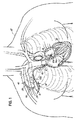
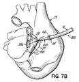
システム10は、患者20の心臓15の左心房14内に通る遠位端部分12aを備える流入カニューレ12を含む。たとえば心臓の左側の任意の部位(たとえば左心房および/または左心室)内にアクセスして、酸素を豊富に含んだ血液にアクセスすることができる。流入カニューレ12は、図7F〜7Gで示したように、左心房壁14aなど心臓15の左側の外壁に直接取り付けられる。後で全般的に論じる手法の1つなど、任意の所望の外科的手法で流入カニューレ12を心臓の外部領域に向けることができる。カニューレ12は、図で示した実施形態では円板様構成を有する遠位固定要素22および近位固定要素24を含む。しかし、固定要素22、24は、前に参照した米国特許出願第60/823,971号で示したような他の構成を有してもよい。カニューレ12をシリコーンなど多様な移植片または医療グレードの材料で作成することができる。
The system 10 includes an
血液循環補助システム10は、入口32と出口34を有する血液ポンプ30、および流出カニューレ36も含む。流入カニューレ12の近位端部分12bは血液ポンプ30の入口32に結合される。特許文献2、特許文献3、特許文献4、および特許文献5、または特許文献6に記載されたものを含む任意の適切な血液ポンプ30を使用することができる。流出カニューレ36は、ポンプ30の出口34と、浅腋窩動脈(superficial axillary artery)40など動脈との間に連結される。したがって、血流は、矢印42の方向に左心房14からポンプ30を通り、流出カニューレ36を通って患者の動脈系に流れる。流出カニューレ36を腋窩動脈40など浅動脈に、適切な外科的切開、ならびに適切な移植片(図示略)および縫合糸(図示略)の使用を含み得る付着処置によって連結することができる。
The blood circulation assist system 10 also includes a blood pump 30 having an inlet 32 and an outlet 34, and an outflow cannula 36. The
血液ポンプ30の移植前または後に、流入カニューレ12および/または流出カニューレ36をポンプ30に連結することができる。最初に流入カニューレ12および/または流出カニューレ36を適切な消毒済みの切断ツール(図示略)で適切な長さに切断して、前に参照した米国特許出願第60/823,971号で示したように、カニューレ12、36をねじらずに、システムをたとえば胸のペースメーカポケット内により容易に移植することができる。
The
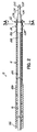
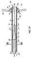
本発明の一実施形態による挿入デバイス200を任意の適した外科的処置で使用して、流入カニューレ12を心臓15に送ることができる。挿入デバイス200は、流入カニューレ12などカニューレと関連した複数の機能を有する。こうした機能は以下を含む:挿入デバイスを流入カニューレ12などカニューレに解放可能に固定することによって、外科医がカニューレを所望のアクセス部位に送り、心臓組織でもよい生体組織を通してカニューレを挿入する能力を向上させ、カニューレと挿入デバイス200の組合せの硬さによって、組織に与える損傷を最小限に押さえるのに使用される拡張可能な部材を提供すること、および穿刺部または切開部など組織の開口部を徐々に拡大して、カニューレの遠位端部分を生体組織を通して挿入しやすい大きさにすること。図2および7A〜7Gを参照して、処置の一例を以下に論じる。図2および7B〜7Eは、ガイドワイヤ50上で流入カニューレ12の管腔16内に挿入された挿入デバイス200を示し、挿入デバイス200は流入カニューレ12に解放可能に固定された状態である。
The
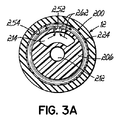
挿入デバイス200は、遠位端部分208(図2)、近位端部分210(図4)、およびその中に形成された管腔212、214(図3A、3B、および4)を有するシャフト206を含む。管腔212は、ガイドワイヤ50など任意の市販のガイドワイヤをその中に受けるように構成される。管腔214は、より詳細に論じるように、たとえば、シリンジから加圧流体、通常は無菌液体をその中に受けるように構成される。管腔212、214は互いに連通しない。シャフト206を高いジュロメータを有する材料から作成することができる。一実施形態では、こうした材料は63D以上のジュロメータを有することができる。適した材料の例には、限定的ではないが、ナイロン、ウレタン、およびPebax(登録商標)など熱可塑性材料が含まれる。任意の他の適した生体適合性材料をシャフト206の作成に使用することができる。
The
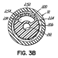
挿入デバイス200はさらに、シャフト206の遠位端部分208に連結された先端部220、シャフト206の近位端部分210に連結されたハブ222、およびシャフト206の遠位端部分208に結合された拡張可能な部材224を含む。図で示した実施形態では、拡張可能な部材224はより具体的には膨張可能な部材である。しかし、後でさらに詳細に論じるように、異なる拡張可能な部材を有する他の挿入デバイスを本発明の態様に従って使用することができる。膨張可能な部材224は遠位端部分208の周囲で少なくとも部分的に拡張することができる。膨張可能な部材224は、たとえば従来のバルーンカテーテルで使用されるようなバルーン様の拡張可能な部材でもよい。図2、3A、7C、7D、および7Eは、挿入デバイス200を流入カニューレ12に解放可能に固定する、膨張したまたは拡張した膨張可能な部材224を示す。図3Bおよび7Fは、挿入デバイス200が流入カニューレ12と係合せず、したがって流入カニューレ12に一時的に固定されない、収縮した、または折りたたまれた膨張可能な部材を示す図である。
先端部220は、シャフト206の管腔212と連通してガイドワイヤ50を受ける中空内部226(図7C)を含む。先端部220の内径は、ガイドワイヤ50など市販のガイドワイヤを収容するサイズであり、通常、ガイドワイヤの外径よりも約0.003インチ以上大きい。後で図7B〜7Eを参照して論じるように、ガイドワイヤ50は、この処置の最初の段階中、先端部220を越えて心臓15の房室14内に突き出る。先端部220は、心臓15の房室14内に挿入され、流入カニューレ12を房室14内に挿入しやすくするように構成される。先端部220の構成によって、心臓組織、この場合は左心房壁14aの切開部が流入カニューレ12を受けるのに十分な大きさになるまで徐々に拡大される。この漸進的拡大は、図2および7B〜7Eで示したように、段付き構成を有する先端部220などによって、または別法として、連続的なテーパを有する先端部(図示略)で行うことができる。いずれの場合も、先端部は近位端部分から遠位端部分まで先細りになされる。
The
先端部220は、先細り部分230、232、および円筒形部分234、236を含むことができる。先細り部分230は、図で示した実施形態では、先端部220の遠位端部分であり、円筒形部分234と一体型である。先細り部分232は、円筒形部分234、および図で示した実施形態では先端部220の近位端部分である円筒形部分236と一体型である。別法として、挿入デバイス200の先端部は追加の先細り部分および円筒形部分を含むことができる。先端部220の各円筒形部分、この場合、円筒形部分234、236は、独特の外径を有し、円筒形部分の最も遠位端、この場合は円筒形部分234から、円筒形部分の最も近位端、この場合は円筒形部分236まで、外径のサイズが次第に大きくなる。たとえば、円筒形部分234は外径d1を有し、円筒形部分236は外径d1よりも大きい外径d2を有する(図7D)。挿入デバイス200の先端部に組み込まれるテーパの数は流入カニューレの内径に依存する。一実施形態では、流入カニューレ12など、流入カニューレの内径が約6mmの場合、先端部220など、挿入デバイス200の先端部は2つのテーパを含むことができる。この例では、円筒形部分234の径d1は約2mmでもよく、円筒形部分236の径d2は約4mmでもよい。しかし、径d1およびd2は、流入カニューレ12など、流入カニューレの内径によって異なる大きさを有する。たとえば、解剖学的構造が先端部220など段付き構成を有する先端部を支持するのに十分大きくない場合、先端部(図示略)に連続的なテーパを設けることができる。たとえば、先端部を挿入すべき心腔にわたる(入口から反対側の壁までの)寸法が複数のテーパを有する先端部の全長よりも小さい場合、1つの連続したテーパを有する比較的短い先端部が使用される。
The
先端部220を、たとえばナイロン、ウレタン、またはPebax(登録商標)など熱可塑性材料から作成することができ、先端部220は、たとえば、バリウムまたはタングステンなど放射線不透過性の充填材を含むことができる。充填材は金属ペーストでもよい。先端部220を他の適した生体適合性ベースおよび充填材から作成することもできる。他の形状、たとえば、陥凹(図示略)を先端部220に形成して、挿入デバイス200の配置中に、経食道心エコー検査または同等の処置が使用される場合に、先端部220の可視性を向上させることができる。
The
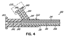
図4で最もよく分かるように、ハブ222はシャフト206の管腔212、214へのアクセスを可能にするように構成される。図で示した実施形態では、ハブ222は、シャフト206の近位端部分210に沿って延びるレッグ240、およびシャフト206の管腔212と連通する管腔242を有する。したがって、管腔242はガイドワイヤ50を受けることができる。ハブ222のレッグ240は、ISO594に従った、または同等のルアーねじ243を含んで、挿入デバイス200の使用前かつ/または後に管腔242を洗い流すことができるようにする。
As best seen in FIG. 4, the
ハブ222はさらにレッグ244を含む。レッグ244は、レッグ240に対して角度を付けることができ、膨張可能な部材224を膨張または収縮させるための、シャフト206の管腔214と流体連通状態の管腔246を含む。シャフト206は、ハブ222に近接するようにシャフト206内に形成されて、この流体連通を確立する少なくとも1つのアパーチャ247を含む。アパーチャ247は切欠きでもよい。レッグ244は流体源に結合されるように合わせれる。流体は、通常は食塩水などの液体であり、加圧することができる。これは、レッグ244の近位端部分に注射器250を受けるためのISO594に従った、または同等のルアーねじ248を設けることによって行うことができる。ハブ222のレッグ244の管腔246は、流体をその中に含むように適合された注射器250の中空内部と流体連通状態である。アパーチャ252は切欠きまたはスカイブ(図3Aおよび3B)でもよく、膨張可能な部材224で覆われたシャフト206の部分内に形成され、シャフト206の管腔214と膨張可能な部材224の中空内部254の間に流体連通をもたらす。
ハブ222を、カテーテル用途に通常使用される材料から作成することができる。適した材料の例には、限定的ではないが、ポリカーボネートおよびナイロンが含まれる。ハブ222を他の適した生体適合性材料から作成することもできる。ハブ222をシャフト206に接着剤または他の従来の手段によって固定することができる。ハブ222は、ハブ222が固定される特定のシャフトの外径を収容するサイズである。
The
図2および7C〜7Fで示したように、膨張可能な部材224は、通常、先端部220の近位に配置され、シャフト206に固定することができる。接着剤、溶融または溶接処理、あるいは他の適した手段あるいは処理を使用して、膨張可能な部材224をシャフト206に固定することができる。膨張可能な部材224は、流入カニューレ12の可撓性を考慮し、部材224が膨張したときに流入カニューレ12を挿入デバイス200に解放可能に固定して、外科医が流入カニューレを心臓15上の所望のアクセス部位に向ける助けをするために使用される。これは、流入カニューレ12の少なくとも遠位端部分12aに剛性を与える。
As shown in FIGS. 2 and 7C-7F, the
膨張可能な部材224は、膨張すると全般的に円筒形のスリーブになる。膨張は、注射器250のプランジャ(図示略)を延長し、これによって注射器の中の流体を加圧し、流体をハブ222のレッグ244の管腔246を通してシャフト206の管腔214内に流すことによって行うことができる。次いで、図3Aの矢印262で示したように、流体は管腔214からシャフト206内のアパーチャ252を通って膨張可能な部材224の中空内部254内に流れる。
The
膨張可能な部材224の長さ、すなわちシャフト206の長手方向の距離は、流入カニューレ12の遠位端部分12aの所望の硬さ、および膨張可能な部材224が膨張したときの膨張可能な部材224の外面と流入カニューレ12の内面の間の関連する接触面によって変わる。たとえば、膨張可能な部材224の長さは、特定の用途によって約5mmから約50mmまで変わることができる。膨張可能な部材224の外径は、部材224が膨張した場合に、流入カニューレ12の内面と約0から約1mmの締め代が得られるサイズでもよい。
The length of the
膨張可能な部材224を、たとえば、ナイロン、PET、ポリエチレン、ポリウレタン、またはPebax(登録商標)など熱可塑性材料から作成することができる。膨張可能な部材224を、他の適した生体適合性材料から作成することもできる。膨張可能な部材224の作成に使用される材料は、通常、少なくとも2atmの定格破裂圧力を有する。膨張可能な部材224の特定の長さについての膨張可能な部材224の壁の厚さは、所望の破裂圧力、材料の特性、および膨張可能な部材224の膨張径に直接関係する。薄い壁のシリンダにフックの法則を用いて、膨張可能な部材224の壁の厚さを決定することができる。
The
流入カニューレ12の遠位端部分12aが房室14内の所望の位置に挿入され、たとえば巾着縫合で心臓15に固定された後、膨張可能な部材224が収縮される。収縮は、注射器250のプランジャを後退させて、流体を膨張可能な部材224の中空内部254から注射器250に戻すことによって行うことができる。シャフト206内の管腔214の体積は、たとえば約30秒以内など、許容される時間内で膨張可能な部材224を膨張させ、収縮させることができるサイズである。膨張可能な部材224が収縮された後、挿入デバイス200を流入カニューレ12から引き抜くことができる。
After the
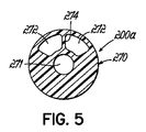
図5は、挿入デバイス200aが挿入デバイス200のシャフト206の代わりにシャフト270を有する以外は、挿入デバイス200と同様の挿入デバイス200aを示す。シャフト270は、ガイドワイヤ50を受けるためのシャフト206の管腔212と同様の管腔271を含む。シャフト206の管腔214など比較的大きい外側管腔の代わりに、シャフト270は、シャフト270の長さに沿って延在するリブ274によって分離された2つの比較的小さい外側管腔272を含む。各管腔272は、膨張可能な部材224の中空内部254、および加圧流体源、この場合は注射器250と流体連通状態である。シャフト270は、近位端および遠位端部分に切欠きまたはスカイブ(図示略)でもよい適切なアパーチャを含んで、それぞれ管腔272とハブ222のレッグ244の管腔246と膨張可能な部材224の中空内部254との間に流体連通をもたらす。リブ274を組み込むことによって、シャフト270の構造特性が向上する。
FIG. 5 shows an
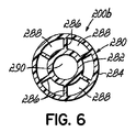
図6は、挿入デバイス200bが挿入デバイス200のシャフト206の代わりにシャフト280を有する以外は、挿入デバイス200と同様の挿入デバイス200bを示す。シャフト280は、同心に配置され、複数の周方向に間隔をおいて配置されたリブ286によって相互連結された内側の円筒形突出部282および外側の円筒形突出部284を含む。突出部282、284、およびリブ286は外側管腔288を画定する。各外側管腔288は、膨張可能な部材224の中空内部254、および加圧流体源、この場合は注射器250と流体連通状態である。シャフト280は、近位端および遠位端部分に切欠きまたはスカイブ(図示略)でもよい適切なアパーチャを含んで、それぞれ管腔288とハブ222のレッグ244の管腔246と膨張可能な部材224の中空内部254との間に流体連通をもたらす。シャフト280はさらにガイドワイヤ50を受けるための内側管腔290を含む。
FIG. 6 shows an insertion device 200b similar to the
他の代替挿入デバイス(図示略)は挿入デバイス200と同様でもよいが、熱可塑性材料など、より可撓性の材料からなる複数の管腔を含む内側シャフトを取り囲む硬いハイポチューブをさらに含むことができる。ハイポチューブは、たとえばステンレス鋼など金属からなるものでもよい。ハイポチューブは、挿入デバイス200などデバイスに対する挿入デバイスの柱の強度を増すものである。代替挿入デバイスは、さらに、内側ひずみ解放部および外側ひずみ解放部を含むことができる。内側ひずみ解放部を構造に追加して、含まれた膨張可能な部材の近位に硬さの変化を与えながら、複数の管腔を含む内側シャフトとハイポチューブの間に障壁を設けることができる。内側ひずみ解放部は、通常は薄い壁のチューブであり、たとえば、Pebax(登録商標)、ナイロン、ポリウレタンなど熱可塑性材料から作成することができるが、ポリエステルチューブなど熱収縮性チューブから作成することもできる。内側ひずみ解放部をハイポチューブの最も近位端(たとえば、含まれた挿入デバイスのハブ付近)に固定することができ、これをたとえば接着剤または熱溶融処理を用いて行うことができる。通常、内側ひずみ解放部の遠位端は定位置に固定されない。それによって、挿入デバイスが挿入中に屈曲部に配置された場合に、複数の管腔を含む内側シャフトと内側ひずみ解放部の間の相互運動が可能になる。外側ひずみ解放部は、ハイポチューブの遠位に延び、内側ひずみ解放部の遠位端の近位で終端となってもよい。この位置付けによって、挿入デバイスの最も硬い構成要素、すなわちハイポチューブから最も可撓性の構成要素、すなわち複数の管腔を含む内側シャフトまで硬さを徐々に変える。外側ひずみ解放部は、Pebax(登録商標)、ナイロン、またはポリウレタンなど熱可塑性材料から作成することができるが、ポリエステル、またはポリオレフィンチューブなど、熱収縮性チューブから作成することもできる。内側と外側のひずみ解放部を組み込むことによって、比較的大きい径の構成要素から比較的小さい径の構成要素まで移行する場所で挿入デバイスのねじれを防ぐ助けをする。
Other alternative insertion devices (not shown) may be similar to
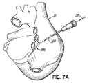
流入カニューレ12を心臓15に連結する処置の一例が図7A〜7Gに示されている。この点で、いわゆるWatersonの溝など、アクセス部位300(図7A)が外科的処置中に露出され、または他の方法でアクセスされる。穿刺部302(図7B)を心臓15の壁14aのアクセス部位300に中空の針304で作成して、左心房14の内部にアクセスし、カニューレ12の遠位端部分12aを挿入することができる。代替外科的処置では、針304で作成する穿刺部302の代わりに、メスで小さい切開部を作成して、左心房14の内部にアクセスすることができる。針304の管腔の径は、ガイドワイヤ50が針304を通過することができる十分な大きさでなければならない。
An example of a procedure for connecting the
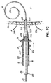
図7Bは、流入カニューレおよび挿入デバイス200が心臓15に近い部位に送られ、ガイドワイヤ50が穿刺部302を通って左心房14内に挿入された状態を示す。ガイドワイヤ50は、通常、左心房14内でループ状になされて、ガイドワイヤ50の遠位先端部50aによる心臓組織への損傷を全て回避する助けをする。図7C〜7Fで示したように、カニューレ12の挿入に備えて、1つまたは複数の巾着縫合糸306、308を穿刺部302の周囲に固定することができる。
FIG. 7B shows the inflow cannula and
図7Cは、挿入デバイス200の先端部220をガイドワイヤ50上で左心房壁14aを横切るように前進させる段階を示す。膨張可能な部材224は、図7C〜7Eで示した段階では膨張されて、挿入デバイス200を流入カニューレ12に一時的に解放可能に固定する。挿入デバイス200の硬さによって、外科医が、心臓組織への損傷を最小限に抑えて、挿入デバイス200および流入カニューレ12をアクセス部位300に正確に送り、挿入デバイス200の先端部220を穿刺部302を通して挿入することができるようになる。膨張可能な部材224は、後で論じるように、縫合糸306、308が固く締め付けられるまで膨張したままとすることができる。
FIG. 7C shows the step of advancing the
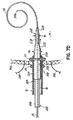
図7Dは、挿入デバイス200の先端部220全体、カニューレ12の遠位端部分12a、およびカニューレ12の遠位固定要素22が左心房14内に挿入された状態の後続の段階を示す。処置によっては、遠位固定要素22および近位固定要素24が左心房14内に最初に挿入されるように、流入カニューレ12を左心房14内に挿入することができる。その場合は図7Dで示したように、次いで流入カニューレ12を僅かに近位に(外科医に向けて)引き出して、近位固定要素24を左心房14の外側に位置付け、遠位固定要素22を左心房14内部に残す。固定要素22、24の材料は、外科グレードのシリコーン、または任意の他の適した生体適合性材料など、可撓性かつ/または弾性の材料でもよい。固定要素22、24は、固定要素22、24の材料の性質により、心臓15の壁14aを通過するときに縮小することができ、左心房14内に挿入された後に元の形状に拡張することができる。別法として、固定要素22、24を、外科医によって操作される任意の適した機構によって、拡張または縮小することもできる。さらに、近位固定要素24が遠位固定要素22よりも小さい径を有して、比較的小さい近位固定要素24が穿刺部302を通って飛び出し、遠位固定要素22が心臓15の壁14aの反対側に対する堅固な停止部として残り、外科医に知覚可能なフィードバックを与えるようにすることができる。
FIG. 7D shows a subsequent stage with the
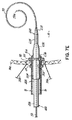
このとき、図7Eで示したように、巾着縫合糸306、308を固く締め付け、結紮して、組織310を遠位固定要素22と近位固定要素24の間で完全に固定し、液密、または少なくとも実質的に液密シールを形成することができる。この点で、締め付けられた組織310は、図7Eで示したように、遠位固定要素22と近位固定要素24の間の隙間内に少なくとも実質的に充満し、または寄せ集められなければならない。組織310をさらに寄せ集める必要がある場合、追加の組織310を1つまたは複数の追加の巾着縫合糸で寄せ集めることができる。固定要素22、24、および壁14aと係合するカニューレ12の一部に漏れ防止シールの形成をさらに助ける組織内殖材料を与えることができる。
At this time, as shown in FIG. 7E, the purse string sutures 306, 308 are tightly clamped and ligated to completely fix the
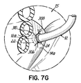
縫合糸306、308を締め付けた後、図7Fで示したように、ガイドワイヤ50および挿入デバイス200を引き出し、図7Fおよび7Gで示したように、カニューレ12の遠位端部分12aを左心房14に挿入したままにし、カニューレ12を心臓15の壁14aに固定した状態にすることができる。
After tightening
前に述べたように、参照により全体が明確に本明細書に組み込まれている、「Cannula Insertion Devices, Systems, and Methods Including a Compressible Member」という名称の同時係属中の米国特許出願第11/846,886号には、血液の損失および/または空気の血液への侵入を有利に防ぐ挿入デバイスの圧縮部材116のシール機能が記載されている。この同じ機能を本明細書で開示した挿入デバイス200の膨張可能な部材224で行うことができる。より具体的には、膨張可能な部材224が十分に膨張すると、膨張可能な部材224は流入カニューレ12の内面とシールを形成する。したがって、図7Dおよび7Eを参照して上述したように、膨張可能な部材224は、カニューレ12の遠位端部分12aが左心房14内に挿入されたときに、流入カニューレ12を通る血液の損失を防ぎ、巾着縫合糸306、308が締め付けられて、カニューレ12が左心房壁14aに固定される。
As previously mentioned, co-pending U.S. Patent Application No. 11 / 846,886, entitled `` Cannula Insertion Devices, Systems, and Methods Including a Compressible Member, '' which is expressly incorporated herein by reference in its entirety. Describes the sealing function of the compression member 116 of the insertion device that advantageously prevents blood loss and / or air penetration into the blood. This same function can be performed with the
さらに、挿入デバイス200を流入カニューレ12から引き抜く過程で、(膨張可能な部材224が収縮されて、カニューレ12の内面と係合していない図7Fとは違い)膨張可能な部材224を部分的に収縮させて、膨張可能な部材224がカニューレ12の内面と接触したままの状態で、挿入デバイス200をカニューレ12に対して摺動させることができる。その場合、挿入デバイス200は空気を除去するピストンのように働く。具体的には、挿入デバイス200は、引き出されるときに真空を生成して、血液を心臓15から流入カニューレ12内に引き出すことができる。血液が、前に流入カニューレ12内に存在した空気と置換される。
Furthermore, in the process of withdrawing the
以下に、代表であって限定的ではない例として、様々な外科的手法をさらに詳述する。こうした手法を使用して、本明細書の上記の様々な態様を実施することができる。 In the following, various surgical procedures are described in further detail as representative and non-limiting examples. Such an approach can be used to implement the various aspects described herein.
胸骨切開術 この手法は、心臓、特に左心房への完全なアクセスを可能にし、血液流入カニューレを心臓に取り付けることができる幾つかの異なる部位へのアクセスを可能にする。しかし、この手法は侵襲性が非常に高いため、外科医には、低侵襲的な体内移植の手法がより望ましい。 Sternotomy This procedure allows full access to the heart, particularly the left atrium, and allows access to several different sites where a blood inflow cannula can be attached to the heart. However, since this technique is very invasive, a minimally invasive internal transplantation technique is more desirable for the surgeon.
開胸術 この外科的手法では、比較的上方および尾側に開胸術によりアクセスして、血液流入カニューレを左心房のカニューレを固定する位置に送る。心房のこの部位は、心房の壁がこの部位で平滑であり、比較的大きく、カニューレの先端部を心房内の他の構造から離すことができるために、特に有益である。 Thoracotomy In this surgical procedure, the upper inflow and caudal side are accessed by thoracotomy and the blood inflow cannula is sent to a position where the left atrial cannula is secured. This location of the atrium is particularly beneficial because the atrial wall is smooth at this location, is relatively large, and the tip of the cannula can be separated from other structures in the atrium.
他の適した外科的方法では、比較的横方向に開胸術によりアクセスして、血液流入カニューレを左心房に送り、血流入カニューレを心房中隔付近の後内側壁上の部位に固定する。この部位は上記で論じたように「Watersonの溝」と呼ばれることが多く、僧帽弁修復手術を行う際に左心房切開を行う一般的な部位である。Watersonの溝は、上大静脈と左心房の左肺静脈の間で終端となる。 In another suitable surgical method, a relatively lateral thoracotomy is accessed to deliver the blood inflow cannula to the left atrium and secure the blood flow cannula at a location on the posterior medial wall near the atrial septum . This site is often referred to as the “Waterson's groove” as discussed above, and is a common site for making a left atrial incision during mitral valve repair surgery. Waterson's groove terminates between the superior vena cava and the left pulmonary vein of the left atrium.
胸腔鏡下手術 この外科的方法では、管状トロカールを使用して、胸腔内部位(たとえばWatersonの溝)にアクセスし、そこにカニューレを心臓壁を通して固定する点で、血液流入カニューレを上記と同様の部位に移植することができる。この最小侵襲的または低侵襲的な外科的方法では、手術全体がこうした比較的小さい管状トロカールによって行われるため、患者の胸の開口の大きさが最小限に抑えられる。通常、追加の小さい孔を作成して、主な送出用トロカールと共に使用されるトロカールを送り、内視鏡カメラ、および把持、切断、縫合、焼灼、または他の操作を組織に行うための特殊な外科ツールを配置することができるようにする。主なトロカールを通して、カニューレを開放外科手術技法と同じ部位(すなわちWatersonの溝)に、胸壁を横切る低侵襲的なアクセスで送ることができる。 Thoracoscopic surgery This surgical method uses a tubular trocar to access an intrathoracic site (e.g., Waterson's groove) and secure the cannula therethrough through the heart wall. Can be transplanted to the site. In this minimally invasive or minimally invasive surgical method, the size of the patient's chest opening is minimized because the entire operation is performed by such a relatively small tubular trocar. Typically, an additional small hole is created to feed the trocar used with the main delivery trocar, an endoscopic camera, and specialized to perform grasping, cutting, suturing, cauterization, or other operations on the tissue Allow surgical tools to be placed. Through the main trocar, the cannula can be delivered to the same site as the open surgical technique (ie Waterson's groove) with minimally invasive access across the chest wall.
オーバーザワイヤ(セルディンガー)技法
セルディンガー技法の変形を上記の様々な外科的移植手法で使用することができ、カニューレシステムを特別に適合させて、この移植技法を容易にすることができる。セルディンガー技法は、通常、血管への経皮的アクセスに関連するものであるが、特別に適合されたカニューレ導入システムを使用する技法の適合バージョンは、心臓に直接アクセスする外科的移植に非常に好ましい手法である。その場合、たとえば、針を心臓壁を通して挿入して、心房切開を行い、次いでガイドワイヤをその針を通して配置することができる。針を除去した後に、出血を制御し、最小限に抑え、その中に特殊な導入栓子を有するカニューレシステムをワイヤ上で導入し、それによって、外科的手法でも、いわゆるセルディンガー技法の多くの利点を維持することができる。
Over-the-wire (Seldinger) technique Variations of the Seldinger technique can be used in the various surgical implantation techniques described above, and the cannula system can be specially adapted to facilitate this implantation technique. The Seldinger technique is usually associated with percutaneous access to blood vessels, but a adapted version of the technique that uses a specially adapted cannula introduction system is highly preferred for surgical implantation with direct access to the heart It is a technique. In that case, for example, a needle can be inserted through the heart wall to make an atrial incision, and then a guide wire can be placed through the needle. After the needle is removed, bleeding is controlled and minimized, and a cannula system with a special introducer plug in it is introduced over the wire, thereby allowing many of the so-called Seldinger techniques, even in surgical procedures. Benefits can be maintained.
本発明を様々な例示の実施形態の記載によって説明し、これらの実施形態を幾分詳細に記載したが、本出願人らは、添付の特許請求の範囲がこうした詳細に決して制限または限定されることを意図しない。本明細書で論じた特徴および態様を任意の適した組合せで使用することができる。当業者は追加の利点および変更を容易に思いつくであろう。たとえば、本明細書で示した実施形態で開示された挿入デバイスは、膨張可能な部材を含んで、それぞれの挿入デバイスをカニューレに解放可能に固定するものであるが、膨張可能な部材ではない他の拡張可能な部材を含む他の構成を有する代替挿入デバイスを本発明の態様により使用して、一時的かつ/または解放可能に挿入デバイスをそれぞれのカニューレに固定することもできる。こうした挿入デバイスの例が、前に参照した同時継続中の米国特許出願第11/846,886号に開示されており、その場合、含まれた拡張可能な部材は圧縮性部材116である。圧縮性部材116は軸方向に圧縮されると半径方向に外側に拡張して、それぞれの挿入デバイスをカニューレに解放可能に固定する。任意の他の適した拡張部材を使用して、関連する挿入デバイスをカニューレに固定することができる。また、先端部220を他の挿入デバイスと共に使用することもできる。たとえば、先端部220を膨張可能な部材224および/またはハブ222を含まない挿入デバイスと共に使用することができる。本発明の様々な特徴をユーザの必要および好みによって単独または任意の組合せで使用することができる。しかし、発明自体は添付の特許請求の範囲によってのみ規定されるべきである。
Although the invention has been described by way of description of various exemplary embodiments and these embodiments have been described in some detail, the Applicants have by no means limited or limited the scope of the appended claims to such details. Not intended. The features and aspects discussed herein can be used in any suitable combination. Those skilled in the art will readily be able to come up with additional advantages and modifications. For example, the insertion devices disclosed in the embodiments shown herein include inflatable members that releasably secure each insertion device to the cannula, but are not inflatable members. Alternative insertion devices having other configurations including the expandable member can also be used according to aspects of the present invention to temporarily and / or releasably secure the insertion device to the respective cannula. An example of such an insertion device is disclosed in previously referenced co-pending US patent application Ser. No. 11 / 846,886, in which case the expandable member included is a compressible member 116. The compressible member 116 expands radially outward when axially compressed to releasably secure each insertion device to the cannula. Any other suitable expansion member can be used to secure the associated insertion device to the cannula. The
10 血液循環補助システム
12 流入カニューレ
12a 遠位端部分
12b 近位端部分
14 左心房
14a 左心房壁
15 心臓
16、212、214、242、246、271、272、288、290 管腔
20 患者
22 遠位固定要素
24 近位固定要素
30 血液ポンプ
32 入口
34 出口
36 流出カニューレ
40 腋窩動脈
50 ガイドワイヤ
50a 遠位先端部
200、200a、200b 挿入デバイス
206、270、280 シャフト
208 遠位端部分
210 近位端部分
222 ハブ
224 膨張可能な部材
226、254 中空内部
230、232 先細り部分
234、236 円筒形部分
240、244 レッグ
243、248 ルアーねじ
247、252 アパーチャ
250 注射器
274、286 リブ
282 内側の円筒形突出部
284 外側の円筒形突出部
300 アクセス部位
302 穿刺部
304 針
306、308 巾着縫合糸
310 組織
10 Blood circulation assistance system
12 Inflow cannula
12a Distal end
12b Proximal end portion
14 Left atrium
14a Left atrial wall
15 heart
16, 212, 214, 242, 246, 271, 272, 288, 290 lumen
20 patients
22 Distal anchoring element
24 Proximal anchoring elements
30 Blood pump
32 entrance
34 Exit
36 Outflow cannula
40 Axillary artery
50 guidewire
50a Distal tip
200, 200a, 200b insertion device
206, 270, 280 shaft
208 Distal end
210 Proximal end portion
222 Hub
224 Inflatable member
226, 254 hollow interior
230, 232 taper
234, 236 Cylindrical part
240, 244 legs
243, 248 Luer thread
247, 252 Aperture
250 syringe
274, 286 ribs
282 Inner cylindrical protrusion
284 Outer cylindrical protrusion
300 Access site
302 Puncture part
304 needles
306, 308 Drawstring suture
310 organization
Claims (20)
管腔を備えた流入カニューレと、
前記流入カニューレの前記管腔内に受けられ、前記流入カニューレの一部を前記心腔内に挿入しやすくするように構成された挿入デバイスと、
を備え、前記挿入デバイスが、
遠位端部分、近位端部分、およびシャフト内に形成された複数の管腔を備えたシャフトであって、第1の管腔がその中にガイドワイヤを受けるように構成され、第2の管腔がその中に加圧流体を受けるように構成されたシャフト、
前記シャフトの前記遠位端部分に連結され、前記心腔内に挿入されるように構成され、前記シャフトの前記第1の管腔と連通する中空内部を備えた先端部、および
前記シャフトの前記遠位端部分に結合され、前記シャフトの前記第2の管腔と流体連通状態の中空内部を含んだ膨張可能な部材であって、前記膨張可能な部材が、前記膨張可能な部材が前記流入カニューレと係合解除された第1の収縮した構成と、前記挿入デバイスが前記流入カニューレに解放可能に固定された第2の膨張した構成と、の間で可動である膨張可能な部材を具備しているシステム。 A blood circulation assist system for increasing blood flow between a patient's heart chamber and a remote site of said patient's circulatory system, comprising:
An inflow cannula with a lumen;
An insertion device received within the lumen of the inflow cannula and configured to facilitate insertion of a portion of the inflow cannula into the heart chamber;
The insertion device comprises:
A shaft having a distal end portion, a proximal end portion, and a plurality of lumens formed in the shaft, wherein the first lumen is configured to receive a guide wire therein, the second lumen A shaft configured to receive a pressurized fluid therein;
A tip connected to the distal end portion of the shaft and configured to be inserted into the heart chamber, the tip having a hollow interior communicating with the first lumen of the shaft; and the shaft An inflatable member coupled to a distal end portion and including a hollow interior in fluid communication with the second lumen of the shaft, wherein the inflatable member is the inflatable member. An inflatable member movable between a first contracted configuration disengaged from the cannula and a second expanded configuration in which the insertion device is releasably secured to the inflow cannula. System.
前記シャフトの前記近位端部分に連結されたハブを備え、前記ハブは第1の管腔を備えた第1のレッグを具備し、前記第1の管腔は前記シャフトの前記第1の管腔と連通するように前記第1のレッグ内に形成されており、前記ハブは第2の管腔を備えた第2のレッグをさらに具備し、前記第2の管腔は前記シャフトの前記第2の管腔と流体連通状態で前記第2のレッグ内に形成されて、前記第2のレッグが流体源に結合されるように構成されている、請求項1に記載のシステム。 The insertion device further comprises:
A hub connected to the proximal end portion of the shaft, the hub including a first leg having a first lumen, the first lumen being the first tube of the shaft; Formed in the first leg to communicate with a cavity, the hub further comprising a second leg with a second lumen, the second lumen being the first leg of the shaft. The system of claim 1, wherein the system is configured in fluid communication with a second lumen and formed in the second leg such that the second leg is coupled to a fluid source.
流出カニューレの一端が前記血液ポンプの前記出口に結合され、流出カニューレの反対側の端部が前記患者の動脈に結合されるように構成された流出カニューレをさらに備え、
前記流入カニューレの前記近位端部分が前記血液ポンプの前記入口に結合され、前記流入カニューレの前記遠位端部分が前記心腔内に挿入されるように構成されている、請求項1に記載のシステム。 A blood pump with an inlet and an outlet, and an outflow cannula configured such that one end of an outflow cannula is coupled to the outlet of the blood pump and the opposite end of the outflow cannula is coupled to the patient's artery In addition,
2. The proximal end portion of the inflow cannula is coupled to the inlet of the blood pump, and the distal end portion of the inflow cannula is configured to be inserted into the heart chamber. System.
管腔を備えたカニューレと、
前記カニューレの前記管腔内に受けられ、前記カニューレの一部を前記生体組織を通して挿入しやすくするように構成された挿入デバイスと、
を備え、前記挿入デバイスが、
近位端部分および遠位端部分を有するシャフト、
前記シャフトの前記遠位端部分に連結され、前記生体組織を通して挿入されるように構成された先端部、および
前記シャフトの前記遠位端部分に結合された拡張可能な部材であって、前記拡張可能な部材が、前記拡張可能な部材が前記流入カニューレと係合解除された第1の構成と、前記拡張可能な部材が前記流入カニューレに解放可能に固定された第2の構成と、の間で可動である拡張可能な部材を具備しているシステム。 A system for inserting a cannula through living tissue,
A cannula with a lumen;
An insertion device received within the lumen of the cannula and configured to facilitate insertion of a portion of the cannula through the biological tissue;
The insertion device comprises:
A shaft having a proximal end portion and a distal end portion;
A tip coupled to the distal end portion of the shaft and configured to be inserted through the biological tissue; and an expandable member coupled to the distal end portion of the shaft, the expansion portion An expandable member between a first configuration in which the expandable member is disengaged from the inflow cannula and a second configuration in which the expandable member is releasably secured to the inflow cannula. A system comprising an expandable member that is movable at
挿入デバイスを前記流入カニューレの前記管腔内に挿入し、前記挿入デバイスの先端部の少なくとも一部が前記流入カニューレの遠位端部分を越えて突出し、前記挿入デバイスがさらにシャフトを含み、前記先端部が前記シャフトの遠位端部分に固定され、拡張可能な部材が前記シャフトの前記遠位端部分に結合される段階と、
前記拡張可能な部材を拡張して、前記流入カニューレを前記挿入デバイスに解放可能に固定する段階と、
前記挿入デバイスの前記先端部および前記流入カニューレの前記遠位端部分を前記心腔内に挿入する段階と、を含んでいる方法。 A method of inserting an inflow cannula having a lumen into a patient's heart chamber, comprising:
An insertion device is inserted into the lumen of the inflow cannula, at least a portion of the tip of the insertion device projects beyond a distal end portion of the inflow cannula, the insertion device further comprising a shaft, the tip A portion is secured to the distal end portion of the shaft and an expandable member is coupled to the distal end portion of the shaft;
Expanding the expandable member to releasably secure the inflow cannula to the insertion device;
Inserting the tip of the insertion device and the distal end portion of the inflow cannula into the heart chamber.
前記カニューレを前記心臓組織に固定した後に、前記拡張可能な部材を前記カニューレから係合解除する段階、をさらに含んでいる、請求項10に記載の方法。 Securing the inflow cannula to the heart tissue defining the cavity; and, after securing the cannula to the heart tissue, disengaging the expandable member from the cannula. The method according to claim 10.
拡張が、前記膨張可能な部材を膨張させる段階をさらに含み、係合解除が前記膨張可能な部材を収縮させる段階をさらに含んでいる、請求項11に記載の方法。 The expandable member is an expandable member;
12. The method of claim 11, wherein expansion further comprises inflating the inflatable member and disengaging further comprises deflating the inflatable member.
加圧流体を前記挿入デバイスの前記シャフト内に形成された管腔を通して前記膨張可能な部材の中空内部内に向ける段階をさらに含んでいる、請求項12に記載の方法。 Expansion of the expandable member,
13. The method of claim 12, further comprising directing pressurized fluid through a lumen formed in the shaft of the insertion device and into the hollow interior of the inflatable member.
前記穿刺部を前記挿入デバイスの前記先端部で徐々に拡大し、より大きいサイズにして、前記流入カニューレの前記遠位端部分を前記心腔内に挿入しやすくする段階をさらに含んでいる、請求項10に記載の方法。 Creating a puncture in the tissue defining the cavity; and gradually expanding the puncture at the tip of the insertion device to a larger size so that the distal end portion of the inflow cannula is in the heart 11. The method of claim 10, further comprising facilitating insertion into the cavity.
挿入デバイスの遠位端部分を前記流入カニューレの遠位端部分に一時的に固定する段階と、
前記挿入デバイスの先端部を前記心腔内に挿入する段階と、
前記流入カニューレの前記遠位端部分を前記心腔内に挿入する段階と、
前記挿入デバイスの前記遠位端部分を前記流入カニューレの前記遠位端部分から解放する段階と、
前記挿入デバイスを前記流入カニューレから引き抜く段階と、を含んでいる方法。 A method of inserting an inflow cannula into a patient's heart chamber,
Temporarily securing a distal end portion of an insertion device to a distal end portion of the inflow cannula;
Inserting the distal end of the insertion device into the heart chamber;
Inserting the distal end portion of the inflow cannula into the heart chamber;
Releasing the distal end portion of the insertion device from the distal end portion of the inflow cannula;
Withdrawing the insertion device from the inflow cannula.
前記開口部を前記挿入デバイスの前記先端部で徐々に拡大し、より大きいサイズにして、前記流入カニューレの前記遠位端部分を前記心腔内に挿入しやすくする段階と、をさらに含んでいる、請求項16に記載の方法。 Creating an opening in the tissue defining the cavity;
Gradually expanding the opening at the tip of the insertion device to a larger size to facilitate insertion of the distal end portion of the inflow cannula into the heart chamber. The method of claim 16.
挿入デバイスを前記カニューレの前記管腔内に挿入し、前記挿入デバイスの先端部の少なくとも一部が前記カニューレの遠位端部分を越えて突出し、前記挿入デバイスがさらにシャフトを含み、前記先端部が前記シャフトの遠位端部分に固定され、拡張可能な部材が前記シャフトの前記遠位端部分に結合される段階と、
前記拡張可能な部材を拡張して、前記カニューレを前記挿入デバイスに解放可能に固定する段階と、
前記挿入デバイスの少なくとも前記先端部および前記カニューレの前記遠位端部分を前記組織を通して挿入する段階と、を含んでいる方法。 A method of inserting a cannula having a lumen through a living tissue,
An insertion device is inserted into the lumen of the cannula, at least a portion of the tip of the insertion device projects beyond a distal end portion of the cannula, the insertion device further includes a shaft, and the tip is Affixed to the distal end portion of the shaft and an expandable member coupled to the distal end portion of the shaft;
Expanding the expandable member to releasably secure the cannula to the insertion device;
Inserting at least the tip of the insertion device and the distal end portion of the cannula through the tissue.
前記膨張可能な部材を膨張して、前記カニューレを前記挿入デバイスに解放可能に固定する段階を含んでいる、請求項18に記載の方法。 The expandable member is an inflatable member, and the expansion further comprises:
19. The method of claim 18, comprising inflating the expandable member to releasably secure the cannula to the insertion device.
前記腔を画定する前記組織に開口部を作成する段階、および
前記開口部を前記挿入デバイスの前記先端部で徐々に拡大し、より大きいサイズにして、前記カニューレの前記遠位端部分を前記組織を通して挿入しやすくする段階、をさらに含んでいる、請求項18に記載の方法。 Expansion creates an opening in the tissue defining the cavity, and the opening is gradually enlarged at the tip of the insertion device to a larger size so that the distal end portion of the cannula is 20. The method of claim 18, further comprising facilitating insertion through the tissue.
Applications Claiming Priority (3)
| Application Number | Priority Date | Filing Date | Title |
|---|---|---|---|
| US11/846,839 | 2007-08-29 | ||
| US11/846,839 US7905823B2 (en) | 2006-08-30 | 2007-08-29 | Devices, methods and systems for establishing supplemental blood flow in the circulatory system |
| PCT/US2008/071938 WO2009045624A1 (en) | 2007-08-29 | 2008-08-01 | Devices, methods and systems for establishing supplemental circulatory blood flow |
Publications (2)
| Publication Number | Publication Date |
|---|---|
| JP2010537726A true JP2010537726A (en) | 2010-12-09 |
| JP5555628B2 JP5555628B2 (en) | 2014-07-23 |
Family
ID=40527434
Family Applications (1)
| Application Number | Title | Priority Date | Filing Date |
|---|---|---|---|
| JP2010523013A Expired - Fee Related JP5555628B2 (en) | 2007-08-29 | 2008-08-01 | Devices, methods, and systems for establishing assistance in blood circulation |
Country Status (5)
| Country | Link |
|---|---|
| US (4) | US7905823B2 (en) |
| EP (1) | EP2170431B1 (en) |
| JP (1) | JP5555628B2 (en) |
| CA (1) | CA2688601C (en) |
| WO (1) | WO2009045624A1 (en) |
Cited By (5)
| Publication number | Priority date | Publication date | Assignee | Title |
|---|---|---|---|---|
| JP2016504103A (en) * | 2012-12-21 | 2016-02-12 | エーツェーペー エントヴィッケルングゲゼルシャフト エムベーハー | Sheath assembly for inserting a string element, particularly a catheter, into a patient's body |
| WO2019009256A1 (en) * | 2017-07-04 | 2019-01-10 | シャープ株式会社 | Endoscopic camera device and endoscopic monitoring camera system |
| JP2020049034A (en) * | 2018-09-28 | 2020-04-02 | 国立大学法人東北大学 | Blood circulation device and blood circulation device assembling method |
| JP2023036928A (en) * | 2014-11-14 | 2023-03-14 | ユニバーシティ・オブ・メリーランド・ボルティモア | self sealing cannula |
| JP2023073269A (en) * | 2014-07-04 | 2023-05-25 | アビオメド オイローパ ゲーエムベーハー | Sheath for sealed access to blood vessels |
Families Citing this family (40)
| Publication number | Priority date | Publication date | Assignee | Title |
|---|---|---|---|---|
| US6889082B2 (en) | 1997-10-09 | 2005-05-03 | Orqis Medical Corporation | Implantable heart assist system and method of applying same |
| US9138228B2 (en) | 2004-08-11 | 2015-09-22 | Emory University | Vascular conduit device and system for implanting |
| US7905823B2 (en) * | 2006-08-30 | 2011-03-15 | Circulite, Inc. | Devices, methods and systems for establishing supplemental blood flow in the circulatory system |
| US8333686B2 (en) * | 2006-08-30 | 2012-12-18 | Circulite, Inc. | Cannula insertion devices, systems, and methods including a compressible member |
| US7846123B2 (en) | 2007-04-24 | 2010-12-07 | Emory University | Conduit device and system for implanting a conduit device in a tissue wall |
| PL2349383T3 (en) * | 2008-10-10 | 2022-09-19 | Medicaltree Patent Ltd. | Heart help device and system |
| WO2010071810A1 (en) * | 2008-12-19 | 2010-06-24 | Andy Christopher Kiser | Methods and devices for endoscopic access to the heart |
| US20110118833A1 (en) * | 2009-11-15 | 2011-05-19 | Thoratec Corporation | Attachment device and method |
| US20110118829A1 (en) * | 2009-11-15 | 2011-05-19 | Thoratec Corporation | Attachment device and method |
| US8152845B2 (en) | 2009-12-30 | 2012-04-10 | Thoratec Corporation | Blood pump system with mounting cuff |
| WO2012019126A1 (en) * | 2010-08-06 | 2012-02-09 | Heartware, Inc. | Conduit device for use with a ventricular assist device |
| CN103228300A (en) | 2010-09-07 | 2013-07-31 | 保罗·A·斯彭斯 | Intubation Systems and Methods |
| DK3189862T3 (en) | 2010-12-01 | 2020-05-04 | Abiomed Inc | THE FILLING GUIDE LUM |
| JP6130302B2 (en) | 2011-01-28 | 2017-05-17 | アピカ カーディオヴァスキュラー リミテッド | System for sealing tissue wall stings |
| AU2012212215B2 (en) | 2011-02-01 | 2015-07-30 | Emory University | Systems for implanting and using a conduit within a tissue wall |
| EP2995327A1 (en) | 2011-03-02 | 2016-03-16 | Thoratec Corporation | Ventricular cuff |
| US10307167B2 (en) | 2012-12-14 | 2019-06-04 | Corquest Medical, Inc. | Assembly and method for left atrial appendage occlusion |
| US20150025312A1 (en) * | 2011-08-09 | 2015-01-22 | Didier De Canniere | Introductory assembly and method for inserting intracardiac instruments |
| US10314594B2 (en) | 2012-12-14 | 2019-06-11 | Corquest Medical, Inc. | Assembly and method for left atrial appendage occlusion |
| US10813630B2 (en) | 2011-08-09 | 2020-10-27 | Corquest Medical, Inc. | Closure system for atrial wall |
| US9981076B2 (en) | 2012-03-02 | 2018-05-29 | Tc1 Llc | Ventricular cuff |
| US9199019B2 (en) | 2012-08-31 | 2015-12-01 | Thoratec Corporation | Ventricular cuff |
| US9585991B2 (en) * | 2012-10-16 | 2017-03-07 | Heartware, Inc. | Devices, systems, and methods for facilitating flow from the heart to a blood pump |
| WO2014117087A1 (en) | 2013-01-25 | 2014-07-31 | Apica Cardiovascular Limited | Systems and methods for percutaneous access, stabilization and closure of organs |
| JP6302992B2 (en) | 2013-03-15 | 2018-03-28 | エーピーケー アドバンスド メディカル テクノロジーズ,インコーポレイテッド | Connector for implantation into the tissue wall |
| US10449274B2 (en) * | 2013-06-26 | 2019-10-22 | Circulite, Inc. | System and method of facilitating connection between cannulae and a blood pump |
| WO2015085094A1 (en) | 2013-12-04 | 2015-06-11 | Heartware, Inc. | Apparatus and methods for cutting an atrial wall |
| JP2017519545A (en) | 2014-05-20 | 2017-07-20 | サーキュライト,インコーポレイテッド | Cardiac support system and method |
| EP4736932A2 (en) * | 2014-07-04 | 2026-05-06 | Abiomed Europe GmbH | Sheath for sealed access to a vessel |
| AU2014402333A1 (en) * | 2014-08-01 | 2017-02-16 | Vadovations, Inc. | Coring dilator for defining an aperture in a tissue wall |
| WO2016070025A1 (en) | 2014-10-31 | 2016-05-06 | Thoratec Corporation | Apical connectors and instruments for use in a heart wall |
| US9717830B2 (en) | 2015-10-28 | 2017-08-01 | Circulite, Inc. | Inflow cannula and blood flow assist system |
| CN108472422B (en) | 2015-12-21 | 2020-06-30 | 心脏器械股份有限公司 | Implantable Mechanical Circulatory Support Devices |
| CN108541223A (en) | 2015-12-21 | 2018-09-14 | 心脏器械股份有限公司 | Axial-flow type with outlet volute can plant Mechanical circulatory support equipment |
| WO2018039124A1 (en) | 2016-08-22 | 2018-03-01 | Tc1 Llc | Heart pump cuff |
| CA3045157A1 (en) * | 2016-11-28 | 2018-05-31 | Inova Medical Pty Ltd | Percutaneous drainage device |
| US11235137B2 (en) | 2017-02-24 | 2022-02-01 | Tc1 Llc | Minimally invasive methods and devices for ventricular assist device implantation |
| WO2018187225A1 (en) * | 2017-04-03 | 2018-10-11 | Henry Ford Health System | Antegrade hemodynamic support |
| EP3552635A1 (en) * | 2018-04-09 | 2019-10-16 | Berlin Heart GmbH | Cannula system and method for volume relief of a heart |
| US11097115B2 (en) * | 2018-09-24 | 2021-08-24 | Galvani Bioelectronics Limited | Implantable pulse generator with suture holes and methods for implanting the same |
Citations (6)
| Publication number | Priority date | Publication date | Assignee | Title |
|---|---|---|---|---|
| JPH02297380A (en) * | 1989-01-30 | 1990-12-07 | Advanced Cardiovascular Syst Inc | Blood vessel catheter |
| JPH10305094A (en) * | 1997-05-09 | 1998-11-17 | Buaayu:Kk | Blood sending canula and blood sending device |
| JP2001504365A (en) * | 1996-11-07 | 2001-04-03 | セン ジュード メディカル カルディオバスキュラー グループ,インコーポレイテッド | Medical graft connectors and fasteners |
| JP2002177284A (en) * | 2000-11-14 | 2002-06-25 | Levram Medical Devices Ltd | Cannulating device, cannulating method and ventricular cannulating device |
| US20040236170A1 (en) * | 2000-11-15 | 2004-11-25 | Ducksoo Kim | Method for surgically joining a ventricular assist device to the cardiovascular system of a living subject using a piercing introducer assembly |
| JP2007020972A (en) * | 2005-07-20 | 2007-02-01 | Pentax Corp | Endoscopic balloon catheter for endoscope |
Family Cites Families (109)
| Publication number | Priority date | Publication date | Assignee | Title |
|---|---|---|---|---|
| US2935068A (en) * | 1955-08-04 | 1960-05-03 | Donaldson John Shearman | Surgical procedure and apparatus for use in carrying out the same |
| US3195540A (en) * | 1963-03-29 | 1965-07-20 | Louis C Waller | Power supply for body implanted instruments |
| US3433227A (en) * | 1965-10-25 | 1969-03-18 | Edward L Kettenbach | Surgical drains |
| US3903895A (en) * | 1973-01-05 | 1975-09-09 | Sherwood Medical Ind Inc | Cardiovascular catheter |
| US3942535A (en) * | 1973-09-27 | 1976-03-09 | G. D. Searle & Co. | Rechargeable tissue stimulating system |
| US4033331A (en) * | 1975-07-17 | 1977-07-05 | Guss Stephen B | Cardiac catheter and method of using same |
| US4534761A (en) * | 1981-08-14 | 1985-08-13 | Bentley Laboratories, Inc. | Implant device |
| AU598200B2 (en) | 1985-07-30 | 1990-06-21 | Advanced Cardiovascular Systems Inc. | Dual dilation catheter assembly and miniature balloon dilatation catheter for use therewith |
| US4790825A (en) * | 1986-09-05 | 1988-12-13 | Electro Catheter Corporation | Closed chest cannulation method and device for atrial-major artery bypass |
| US5697936A (en) * | 1988-11-10 | 1997-12-16 | Cook Pacemaker Corporation | Device for removing an elongated structure implanted in biological tissue |
| US4995857A (en) * | 1989-04-07 | 1991-02-26 | Arnold John R | Left ventricular assist device and method for temporary and permanent procedures |
| IT1240111B (en) * | 1990-02-21 | 1993-11-27 | Sorin Biomedica Spa | SUTURE RING FOR CARDIAC VALVE PROSTHESES |
| US5514153A (en) * | 1990-03-02 | 1996-05-07 | General Surgical Innovations, Inc. | Method of dissecting tissue layers |
| US5190528A (en) * | 1990-10-19 | 1993-03-02 | Boston University | Percutaneous transseptal left atrial cannulation system |
| US5234408A (en) * | 1990-11-20 | 1993-08-10 | Griffith Donald P | Tissue bondable cystostomy tube and method of cystostomy tube implantation |
| US5449342A (en) * | 1991-09-30 | 1995-09-12 | Nippon Zeon Co., Ltd. | Apparatus for assisting blood circulation |
| US5256146A (en) * | 1991-10-11 | 1993-10-26 | W. D. Ensminger | Vascular catheterization system with catheter anchoring feature |
| FR2685208B1 (en) * | 1991-12-23 | 1998-02-27 | Ela Medical Sa | VENTRICULAR CANNULA DEVICE. |
| US5171218A (en) * | 1992-01-02 | 1992-12-15 | Trustees Of Boston University | Bidirectional femoral arterial cannula |
| US5290227A (en) * | 1992-08-06 | 1994-03-01 | Pasque Michael K | Method of implanting blood pump in ascending aorta or main pulmonary artery |
| US5344443A (en) * | 1992-09-17 | 1994-09-06 | Rem Technologies, Inc. | Heart pump |
| US5300107A (en) * | 1992-10-22 | 1994-04-05 | Medtronic, Inc. | Universal tined myocardial pacing lead |
| US5287852A (en) * | 1993-01-13 | 1994-02-22 | Direct Trends International Ltd. | Apparatus and method for maintaining a tracheal stoma |
| US5797960A (en) * | 1993-02-22 | 1998-08-25 | Stevens; John H. | Method and apparatus for thoracoscopic intracardiac procedures |
| US5338301A (en) * | 1993-08-26 | 1994-08-16 | Cordis Corporation | Extendable balloon-on-a-wire catheter, system and treatment procedure |
| WO1995007109A1 (en) * | 1993-09-10 | 1995-03-16 | Ottawa Heart Institute Research Corporation | Electrohydraulic ventricular assist device |
| US5947892A (en) * | 1993-11-10 | 1999-09-07 | Micromed Technology, Inc. | Rotary blood pump |
| EP1402908A3 (en) * | 1994-04-15 | 2005-04-27 | Allegheny-Singer Research Institute | Blood pump device and method of producing |
| US5545191A (en) * | 1994-05-06 | 1996-08-13 | Alfred E. Mann Foundation For Scientific Research | Method for optimally positioning and securing the external unit of a transcutaneous transducer of the skin of a living body |
| US5478309A (en) * | 1994-05-27 | 1995-12-26 | William P. Sweezer, Jr. | Catheter system and method for providing cardiopulmonary bypass pump support during heart surgery |
| IL111953A (en) * | 1994-12-12 | 2012-04-30 | Medical Influence Technologies Ltd | Device for catheter fixation |
| US5743845A (en) * | 1995-01-12 | 1998-04-28 | Runge; Thomas M. | Biventricular pulsatile cardiac support system having a mechanically balanced stroke volume |
| US5658309A (en) | 1995-05-01 | 1997-08-19 | C. R. Bard, Inc. | Guidewire/inflation tube locking apparatus and method of use |
| US5938412A (en) * | 1995-06-01 | 1999-08-17 | Advanced Bionics, Inc. | Blood pump having rotor with internal bore for fluid flow |
| US5924848A (en) * | 1995-06-01 | 1999-07-20 | Advanced Bionics, Inc. | Blood pump having radial vanes with enclosed magnetic drive components |
| US5924975A (en) * | 1995-08-30 | 1999-07-20 | International Business Machines Corporation | Linear pump |
| US5840070A (en) * | 1996-02-20 | 1998-11-24 | Kriton Medical, Inc. | Sealless rotary blood pump |
| US5695471A (en) * | 1996-02-20 | 1997-12-09 | Kriton Medical, Inc. | Sealless rotary blood pump with passive magnetic radial bearings and blood immersed axial bearings |
| DE19613564C1 (en) * | 1996-04-04 | 1998-01-08 | Guenter Prof Dr Rau | Intravascular blood pump |
| US5738649A (en) * | 1996-04-16 | 1998-04-14 | Cardeon Corporation | Peripheral entry biventricular catheter system for providing access to the heart for cardiopulmonary surgery or for prolonged circulatory support of the heart |
| US6074180A (en) | 1996-05-03 | 2000-06-13 | Medquest Products, Inc. | Hybrid magnetically suspended and rotated centrifugal pumping apparatus and method |
| US6270477B1 (en) * | 1996-05-20 | 2001-08-07 | Percusurge, Inc. | Catheter for emboli containment |
| US5676670A (en) * | 1996-06-14 | 1997-10-14 | Beth Israel Deaconess Medical Center | Catheter apparatus and method for creating a vascular bypass in-vivo |
| DE19625300A1 (en) * | 1996-06-25 | 1998-01-02 | Guenter Prof Dr Rau | Blood pump |
| DE19629614A1 (en) * | 1996-07-23 | 1998-01-29 | Cardiotools Herzchirurgietechn | Left-heart assist pump for post-operative period |
| US5921971A (en) * | 1996-09-13 | 1999-07-13 | Boston Scientific Corporation | Single operator exchange biliary catheter |
| US5944745A (en) * | 1996-09-25 | 1999-08-31 | Medtronic, Inc. | Implantable medical device capable of prioritizing diagnostic data and allocating memory for same |
| ES2227718T3 (en) * | 1996-10-04 | 2005-04-01 | United States Surgical Corporation | CIRCULATORY SUPPORT SYSTEM. |
| US5741316A (en) * | 1996-12-02 | 1998-04-21 | Light Sciences Limited Partnership | Electromagnetic coil configurations for power transmission through tissue |
| US6406420B1 (en) * | 1997-01-02 | 2002-06-18 | Myocor, Inc. | Methods and devices for improving cardiac function in hearts |
| WO1998033435A1 (en) * | 1997-01-30 | 1998-08-06 | Boston Scientific Corporation | Pneumatically actuated tissue sampling device |
| DE69821936T2 (en) * | 1997-06-25 | 2004-12-16 | Biotap A/S | TRANSCUTANEOUS IMPLANT DEVICE |
| US6532964B2 (en) | 1997-07-11 | 2003-03-18 | A-Med Systems, Inc. | Pulmonary and circulatory blood flow support devices and methods for heart surgery procedures |
| US6123725A (en) * | 1997-07-11 | 2000-09-26 | A-Med Systems, Inc. | Single port cardiac support apparatus |
| US5858009A (en) * | 1997-08-14 | 1999-01-12 | Medtronic, Inc. | Multi-lumen cannula |
| EP1019117B2 (en) * | 1997-10-02 | 2015-03-18 | Micromed Technology, Inc. | Controller module for implantable pump system |
| US6889082B2 (en) * | 1997-10-09 | 2005-05-03 | Orqis Medical Corporation | Implantable heart assist system and method of applying same |
| UA56262C2 (en) * | 1997-10-09 | 2003-05-15 | Орквіс Медікел Корпорейшн | Extracardiac pumping system for supplementing blood circulation |
| US6354299B1 (en) * | 1997-10-27 | 2002-03-12 | Neuropace, Inc. | Implantable device for patient communication |
| US6540693B2 (en) * | 1998-03-03 | 2003-04-01 | Senorx, Inc. | Methods and apparatus for securing medical instruments to desired locations in a patients body |
| US6186999B1 (en) * | 1998-08-27 | 2001-02-13 | The Cleveland Clinic Foundation | Rigid clampable cannula |
| US5948006A (en) * | 1998-10-14 | 1999-09-07 | Advanced Bionics Corporation | Transcutaneous transmission patch |
| US6475222B1 (en) * | 1998-11-06 | 2002-11-05 | St. Jude Medical Atg, Inc. | Minimally invasive revascularization apparatus and methods |
| US6001056A (en) * | 1998-11-13 | 1999-12-14 | Baxter International Inc. | Smooth ventricular assist device conduit |
| DE29821565U1 (en) * | 1998-12-02 | 2000-06-15 | Impella Cardiotechnik AG, 52074 Aachen | Bearingless blood pump |
| WO2000037139A1 (en) * | 1998-12-23 | 2000-06-29 | A-Med Systems, Inc. | Left and right side heart support |
| US7288096B2 (en) * | 2003-01-17 | 2007-10-30 | Origin Medsystems, Inc. | Apparatus for placement of cardiac defibrillator and pacer |
| US6613062B1 (en) * | 1999-10-29 | 2003-09-02 | Medtronic, Inc. | Method and apparatus for providing intra-pericardial access |
| US20030093104A1 (en) * | 1999-10-29 | 2003-05-15 | Bonner Matthew D. | Methods and apparatus for providing intra-pericardial access |
| US6669708B1 (en) * | 1999-12-09 | 2003-12-30 | Michael Nissenbaum | Devices, systems and methods for creating sutureless on-demand vascular anastomoses and hollow organ communication channels |
| US6632200B2 (en) * | 2000-01-25 | 2003-10-14 | St. Jude Medical, Daig Division | Hemostasis valve |
| DE10016422B4 (en) * | 2000-04-01 | 2013-10-31 | Impella Cardiosystems Ag | Paracardiac blood pump |
| US6530876B1 (en) | 2000-04-25 | 2003-03-11 | Paul A. Spence | Supplemental heart pump methods and systems for supplementing blood through the heart |
| DE10040403A1 (en) * | 2000-08-18 | 2002-02-28 | Impella Cardiotech Ag | Intracardiac blood pump |
| US6994666B2 (en) * | 2001-06-05 | 2006-02-07 | Edwards Lifesciences Corporation | Non-porous smooth ventricular assist device conduit |
| US7054822B2 (en) * | 2001-08-06 | 2006-05-30 | Ecolab, Inc. | Notification of time-critical situations occurring at destination facilities |
| US20030181843A1 (en) * | 2002-06-11 | 2003-09-25 | Scout Medical Technologies, Llc | Device and method providing arterial blood flow for perfusion of ischemic myocardium |
| US20040024285A1 (en) * | 2002-06-21 | 2004-02-05 | Helmut Muckter | Blood pump with impeller |
| US8303511B2 (en) * | 2002-09-26 | 2012-11-06 | Pacesetter, Inc. | Implantable pressure transducer system optimized for reduced thrombosis effect |
| US7077801B2 (en) * | 2003-02-19 | 2006-07-18 | Corlife Gbr | Methods and devices for improving cardiac output |
| AU2003901345A0 (en) | 2003-03-21 | 2003-04-03 | Ventracor Limited | Improved cannula |
| US7048681B2 (en) * | 2003-03-28 | 2006-05-23 | Terumo Corporation | Method and apparatus for adjusting a length of the inflow conduit on a ventricular assist device |
| DE10316177B4 (en) * | 2003-04-10 | 2007-05-31 | Cardiac Pacemakers, Inc., St. Paul | Pacemaker electrode arrangement |
| US7317951B2 (en) * | 2003-07-25 | 2008-01-08 | Integrated Sensing Systems, Inc. | Anchor for medical implant placement and method of manufacture |
| WO2005037345A2 (en) | 2003-10-17 | 2005-04-28 | Vanderbilt University | Percutaneously-inserted ventricular assist devices and related methods |
| US7520850B2 (en) * | 2003-11-19 | 2009-04-21 | Transoma Medical, Inc. | Feedback control and ventricular assist devices |
| US9241735B2 (en) * | 2003-12-05 | 2016-01-26 | Onset Medical Corporation | Expandable percutaneous sheath |
| US7780692B2 (en) * | 2003-12-05 | 2010-08-24 | Onset Medical Corporation | Expandable percutaneous sheath |
| US7585290B2 (en) * | 2004-01-20 | 2009-09-08 | Ethicon Endo-Surgery, Inc. | Medical device for providing access |
| US7699864B2 (en) * | 2004-03-18 | 2010-04-20 | Onset Medical Corporation | Expandable medical access device |
| DE102004019721A1 (en) | 2004-03-18 | 2005-10-06 | Medos Medizintechnik Ag | pump |
| US20060135963A1 (en) * | 2004-09-09 | 2006-06-22 | Kick George F | Expandable gastrointestinal sheath |
| US20060135962A1 (en) * | 2004-09-09 | 2006-06-22 | Kick George F | Expandable trans-septal sheath |
| US7892203B2 (en) * | 2004-09-09 | 2011-02-22 | Onset Medical Corporation | Expandable transluminal sheath |
| EP1819391B1 (en) * | 2004-09-09 | 2020-02-19 | Onset Medical Corporation | Expandable transluminal sheath |
| WO2006068841A2 (en) * | 2004-12-21 | 2006-06-29 | C. R. Bard, Inc. | Hemostasis cuff for catheter securement |
| US20060253102A1 (en) * | 2004-12-21 | 2006-11-09 | Nance Edward J | Non-expandable transluminal access sheath |
| US7340288B1 (en) * | 2005-02-07 | 2008-03-04 | Pacesetter, Inc. | Trans-septal intra-cardiac lead system |
| EP2650029B1 (en) | 2006-08-30 | 2015-01-14 | CircuLite, Inc. | Devices and systems for establishing supplemental blood flow in the circulatory system |
| US7905823B2 (en) * | 2006-08-30 | 2011-03-15 | Circulite, Inc. | Devices, methods and systems for establishing supplemental blood flow in the circulatory system |
| EP2061531B1 (en) | 2006-09-14 | 2016-04-13 | CircuLite, Inc. | Intravascular blood pump and catheter |
| WO2008073852A2 (en) * | 2006-12-08 | 2008-06-19 | Onset Medical Corporation | Expandable medical access sheath |
| WO2008079828A2 (en) * | 2006-12-20 | 2008-07-03 | Onset Medical Corporation | Expandable trans-septal sheath |
| US7722568B2 (en) * | 2007-01-29 | 2010-05-25 | Onset Medical Corporation | Expandable intra-aortic balloon pump sheath |
| US8900214B2 (en) * | 2007-03-30 | 2014-12-02 | Onset Medical Corporation | Expandable trans-septal sheath |
| US8343029B2 (en) * | 2007-10-24 | 2013-01-01 | Circulite, Inc. | Transseptal cannula, tip, delivery system, and method |
| WO2009100210A1 (en) * | 2008-02-05 | 2009-08-13 | Silk Road Medical, Inc. | Interventional catheter system and methods |
| US8668668B2 (en) * | 2008-05-14 | 2014-03-11 | Onset Medical Corporation | Expandable iliac sheath and method of use |
| US7951110B2 (en) * | 2008-11-10 | 2011-05-31 | Onset Medical Corporation | Expandable spinal sheath and method of use |
-
2007
- 2007-08-29 US US11/846,839 patent/US7905823B2/en not_active Expired - Fee Related
-
2008
- 2008-08-01 JP JP2010523013A patent/JP5555628B2/en not_active Expired - Fee Related
- 2008-08-01 EP EP08835271.1A patent/EP2170431B1/en active Active
- 2008-08-01 WO PCT/US2008/071938 patent/WO2009045624A1/en not_active Ceased
- 2008-08-01 CA CA2688601A patent/CA2688601C/en not_active Expired - Fee Related
-
2011
- 2011-02-07 US US13/022,105 patent/US9566375B2/en active Active
-
2016
- 2016-12-28 US US15/392,528 patent/US9808564B2/en active Active
-
2017
- 2017-11-02 US US15/801,618 patent/US10518011B2/en active Active
Patent Citations (6)
| Publication number | Priority date | Publication date | Assignee | Title |
|---|---|---|---|---|
| JPH02297380A (en) * | 1989-01-30 | 1990-12-07 | Advanced Cardiovascular Syst Inc | Blood vessel catheter |
| JP2001504365A (en) * | 1996-11-07 | 2001-04-03 | セン ジュード メディカル カルディオバスキュラー グループ,インコーポレイテッド | Medical graft connectors and fasteners |
| JPH10305094A (en) * | 1997-05-09 | 1998-11-17 | Buaayu:Kk | Blood sending canula and blood sending device |
| JP2002177284A (en) * | 2000-11-14 | 2002-06-25 | Levram Medical Devices Ltd | Cannulating device, cannulating method and ventricular cannulating device |
| US20040236170A1 (en) * | 2000-11-15 | 2004-11-25 | Ducksoo Kim | Method for surgically joining a ventricular assist device to the cardiovascular system of a living subject using a piercing introducer assembly |
| JP2007020972A (en) * | 2005-07-20 | 2007-02-01 | Pentax Corp | Endoscopic balloon catheter for endoscope |
Cited By (16)
| Publication number | Priority date | Publication date | Assignee | Title |
|---|---|---|---|---|
| JP2018134475A (en) * | 2012-12-21 | 2018-08-30 | エーツェーペー エントヴィッケルングゲゼルシャフト エムベーハー | Sheath assembly for insertion of cord-shaped element, particularly catheter, into body of patient |
| JP7811924B2 (en) | 2012-12-21 | 2026-02-06 | エーツェーペー エントヴィッケルングゲゼルシャフト エムベーハー | Sheath assembly for inserting a string-shaped element, in particular a catheter, into a patient's body - Patents.com |
| US12453841B2 (en) | 2012-12-21 | 2025-10-28 | Ecp Entwicklungsgesellschaft Mbh | Sheath assembly for insertion of a cord-shaped element, particularly a catheter, into the body of a patient |
| JP2020168512A (en) * | 2012-12-21 | 2020-10-15 | エーツェーペー エントヴィッケルングゲゼルシャフト エムベーハー | Sheath assembly for inserting string elements, especially catheters, into the patient's body |
| US10881836B2 (en) | 2012-12-21 | 2021-01-05 | Ecp Entwicklungsgesellschaft Mbh | Sheath assembly for insertion of a cord-shaped element, particularly a catheter, into the body of a patient |
| JP2023083625A (en) * | 2012-12-21 | 2023-06-15 | エーツェーペー エントヴィッケルングゲゼルシャフト エムベーハー | A sheath assembly for inserting a cord-shaped element, in particular a catheter, into a patient's body |
| JP2016504103A (en) * | 2012-12-21 | 2016-02-12 | エーツェーペー エントヴィッケルングゲゼルシャフト エムベーハー | Sheath assembly for inserting a string element, particularly a catheter, into a patient's body |
| US11628280B2 (en) | 2012-12-21 | 2023-04-18 | Ecp Entwicklungsgesellschaft Mbh | Sheath assembly for insertion of a cord-shaped element, particularly a catheter, into the body of a patient |
| JP7273004B2 (en) | 2012-12-21 | 2023-05-12 | エーツェーペー エントヴィッケルングゲゼルシャフト エムベーハー | A sheath assembly for inserting a cord-shaped element, in particular a catheter, into a patient's body |
| JP2023073269A (en) * | 2014-07-04 | 2023-05-25 | アビオメド オイローパ ゲーエムベーハー | Sheath for sealed access to blood vessels |
| JP7596420B2 (en) | 2014-07-04 | 2024-12-09 | アビオメド オイローパ ゲーエムベーハー | Sheaths for sealed vascular access |
| JP2023036928A (en) * | 2014-11-14 | 2023-03-14 | ユニバーシティ・オブ・メリーランド・ボルティモア | self sealing cannula |
| JPWO2019009256A1 (en) * | 2017-07-04 | 2020-04-23 | シャープ株式会社 | Internal camera device, internal monitoring camera system |
| WO2019009256A1 (en) * | 2017-07-04 | 2019-01-10 | シャープ株式会社 | Endoscopic camera device and endoscopic monitoring camera system |
| JP7233077B2 (en) | 2018-09-28 | 2023-03-06 | 国立大学法人東北大学 | blood circulation device |
| JP2020049034A (en) * | 2018-09-28 | 2020-04-02 | 国立大学法人東北大学 | Blood circulation device and blood circulation device assembling method |
Also Published As
| Publication number | Publication date |
|---|---|
| US20170106130A1 (en) | 2017-04-20 |
| US9808564B2 (en) | 2017-11-07 |
| CA2688601A1 (en) | 2009-04-09 |
| JP5555628B2 (en) | 2014-07-23 |
| US20110137234A1 (en) | 2011-06-09 |
| US20080076959A1 (en) | 2008-03-27 |
| EP2170431A1 (en) | 2010-04-07 |
| US20180117228A1 (en) | 2018-05-03 |
| EP2170431A4 (en) | 2014-07-09 |
| CA2688601C (en) | 2016-04-12 |
| US9566375B2 (en) | 2017-02-14 |
| WO2009045624A1 (en) | 2009-04-09 |
| US7905823B2 (en) | 2011-03-15 |
| EP2170431B1 (en) | 2016-01-06 |
| US10518011B2 (en) | 2019-12-31 |
Similar Documents
| Publication | Publication Date | Title |
|---|---|---|
| JP5555628B2 (en) | Devices, methods, and systems for establishing assistance in blood circulation | |
| JP5819927B2 (en) | Apparatus, method and system for establishing supplemental blood flow in the circulatory system | |
| CN105473107B (en) | Mitral valve spacer and implantation system and method thereof | |
| US10350384B2 (en) | Two-piece transseptal cannula, delivery system, and method of delivery | |
| CN109789255B (en) | Transcatheter devices and systems for delivering in vivo devices | |
| CN108348666B (en) | Inflow cannula and blood flow assist system | |
| JP2022532767A (en) | Blood pumps and related devices, systems, and methods delivered intravascularly | |
| HK1127474B (en) | Systems for establishing supplemental blood flow in the circulatory system | |
| HK1188577B (en) | Devices and systems for establishing supplemental blood flow in the circulatory system |
Legal Events
| Date | Code | Title | Description |
|---|---|---|---|
| A621 | Written request for application examination |
Free format text: JAPANESE INTERMEDIATE CODE: A621 Effective date: 20110801 |
|
| A977 | Report on retrieval |
Free format text: JAPANESE INTERMEDIATE CODE: A971007 Effective date: 20121207 |
|
| A131 | Notification of reasons for refusal |
Free format text: JAPANESE INTERMEDIATE CODE: A131 Effective date: 20121211 |
|
| A521 | Request for written amendment filed |
Free format text: JAPANESE INTERMEDIATE CODE: A523 Effective date: 20130307 |
|
| A02 | Decision of refusal |
Free format text: JAPANESE INTERMEDIATE CODE: A02 Effective date: 20130924 |
|
| A521 | Request for written amendment filed |
Free format text: JAPANESE INTERMEDIATE CODE: A523 Effective date: 20140124 |
|
| A911 | Transfer to examiner for re-examination before appeal (zenchi) |
Free format text: JAPANESE INTERMEDIATE CODE: A911 Effective date: 20140220 |
|
| TRDD | Decision of grant or rejection written | ||
| A01 | Written decision to grant a patent or to grant a registration (utility model) |
Free format text: JAPANESE INTERMEDIATE CODE: A01 Effective date: 20140507 |
|
| A61 | First payment of annual fees (during grant procedure) |
Free format text: JAPANESE INTERMEDIATE CODE: A61 Effective date: 20140602 |
|
| R150 | Certificate of patent or registration of utility model |
Ref document number: 5555628 Country of ref document: JP Free format text: JAPANESE INTERMEDIATE CODE: R150 |
|
| R250 | Receipt of annual fees |
Free format text: JAPANESE INTERMEDIATE CODE: R250 |
|
| R250 | Receipt of annual fees |
Free format text: JAPANESE INTERMEDIATE CODE: R250 |
|
| LAPS | Cancellation because of no payment of annual fees |