EP3552635A1 - Cannula system and method for volume relief of a heart - Google Patents
Cannula system and method for volume relief of a heart Download PDFInfo
- Publication number
- EP3552635A1 EP3552635A1 EP18166385.7A EP18166385A EP3552635A1 EP 3552635 A1 EP3552635 A1 EP 3552635A1 EP 18166385 A EP18166385 A EP 18166385A EP 3552635 A1 EP3552635 A1 EP 3552635A1
- Authority
- EP
- European Patent Office
- Prior art keywords
- cannula
- trocar
- inlet
- shaft
- heart
- Prior art date
- Legal status (The legal status is an assumption and is not a legal conclusion. Google has not performed a legal analysis and makes no representation as to the accuracy of the status listed.)
- Withdrawn
Links
Images


Classifications
-
- A—HUMAN NECESSITIES
- A61—MEDICAL OR VETERINARY SCIENCE; HYGIENE
- A61M—DEVICES FOR INTRODUCING MEDIA INTO, OR ONTO, THE BODY; DEVICES FOR TRANSDUCING BODY MEDIA OR FOR TAKING MEDIA FROM THE BODY; DEVICES FOR PRODUCING OR ENDING SLEEP OR STUPOR
- A61M27/00—Drainage appliance for wounds or the like, i.e. wound drains, implanted drains
- A61M27/002—Implant devices for drainage of body fluids from one part of the body to another
-
- A—HUMAN NECESSITIES
- A61—MEDICAL OR VETERINARY SCIENCE; HYGIENE
- A61M—DEVICES FOR INTRODUCING MEDIA INTO, OR ONTO, THE BODY; DEVICES FOR TRANSDUCING BODY MEDIA OR FOR TAKING MEDIA FROM THE BODY; DEVICES FOR PRODUCING OR ENDING SLEEP OR STUPOR
- A61M60/00—Blood pumps; Devices for mechanical circulatory actuation; Balloon pumps for circulatory assistance
- A61M60/80—Constructional details other than related to driving
- A61M60/855—Constructional details other than related to driving of implantable pumps or pumping devices
- A61M60/857—Implantable blood tubes
-
- A—HUMAN NECESSITIES
- A61—MEDICAL OR VETERINARY SCIENCE; HYGIENE
- A61B—DIAGNOSIS; SURGERY; IDENTIFICATION
- A61B17/00—Surgical instruments, devices or methods, e.g. tourniquets
- A61B17/34—Trocars; Puncturing needles
- A61B17/3417—Details of tips or shafts, e.g. grooves, expandable, bendable; Multiple coaxial sliding cannulas, e.g. for dilating
- A61B17/3421—Cannulas
-
- A—HUMAN NECESSITIES
- A61—MEDICAL OR VETERINARY SCIENCE; HYGIENE
- A61M—DEVICES FOR INTRODUCING MEDIA INTO, OR ONTO, THE BODY; DEVICES FOR TRANSDUCING BODY MEDIA OR FOR TAKING MEDIA FROM THE BODY; DEVICES FOR PRODUCING OR ENDING SLEEP OR STUPOR
- A61M60/00—Blood pumps; Devices for mechanical circulatory actuation; Balloon pumps for circulatory assistance
- A61M60/10—Location thereof with respect to the patient's body
- A61M60/122—Implantable pumps or pumping devices, i.e. the blood being pumped inside the patient's body
- A61M60/165—Implantable pumps or pumping devices, i.e. the blood being pumped inside the patient's body implantable in, on, or around the heart
- A61M60/178—Implantable pumps or pumping devices, i.e. the blood being pumped inside the patient's body implantable in, on, or around the heart drawing blood from a ventricle and returning the blood to the arterial system via a cannula external to the ventricle, e.g. left or right ventricular assist devices
-
- A—HUMAN NECESSITIES
- A61—MEDICAL OR VETERINARY SCIENCE; HYGIENE
- A61M—DEVICES FOR INTRODUCING MEDIA INTO, OR ONTO, THE BODY; DEVICES FOR TRANSDUCING BODY MEDIA OR FOR TAKING MEDIA FROM THE BODY; DEVICES FOR PRODUCING OR ENDING SLEEP OR STUPOR
- A61M60/00—Blood pumps; Devices for mechanical circulatory actuation; Balloon pumps for circulatory assistance
- A61M60/50—Details relating to control
- A61M60/508—Electronic control means, e.g. for feedback regulation
- A61M60/538—Regulation using real-time blood pump operational parameter data, e.g. motor current
- A61M60/554—Regulation using real-time blood pump operational parameter data, e.g. motor current of blood pressure
-
- A—HUMAN NECESSITIES
- A61—MEDICAL OR VETERINARY SCIENCE; HYGIENE
- A61M—DEVICES FOR INTRODUCING MEDIA INTO, OR ONTO, THE BODY; DEVICES FOR TRANSDUCING BODY MEDIA OR FOR TAKING MEDIA FROM THE BODY; DEVICES FOR PRODUCING OR ENDING SLEEP OR STUPOR
- A61M60/00—Blood pumps; Devices for mechanical circulatory actuation; Balloon pumps for circulatory assistance
- A61M60/80—Constructional details other than related to driving
- A61M60/855—Constructional details other than related to driving of implantable pumps or pumping devices
- A61M60/861—Connections or anchorings for connecting or anchoring pumps or pumping devices to parts of the patient's body
- A61M60/863—Apex rings
-
- A—HUMAN NECESSITIES
- A61—MEDICAL OR VETERINARY SCIENCE; HYGIENE
- A61M—DEVICES FOR INTRODUCING MEDIA INTO, OR ONTO, THE BODY; DEVICES FOR TRANSDUCING BODY MEDIA OR FOR TAKING MEDIA FROM THE BODY; DEVICES FOR PRODUCING OR ENDING SLEEP OR STUPOR
- A61M60/00—Blood pumps; Devices for mechanical circulatory actuation; Balloon pumps for circulatory assistance
- A61M60/80—Constructional details other than related to driving
- A61M60/855—Constructional details other than related to driving of implantable pumps or pumping devices
- A61M60/865—Devices for guiding or inserting pumps or pumping devices into the patient's body
-
- A—HUMAN NECESSITIES
- A61—MEDICAL OR VETERINARY SCIENCE; HYGIENE
- A61B—DIAGNOSIS; SURGERY; IDENTIFICATION
- A61B17/00—Surgical instruments, devices or methods, e.g. tourniquets
- A61B17/00234—Surgical instruments, devices or methods, e.g. tourniquets for minimally invasive surgery
- A61B2017/00238—Type of minimally invasive operation
- A61B2017/00243—Type of minimally invasive operation cardiac
- A61B2017/00247—Making holes in the wall of the heart, e.g. laser Myocardial revascularization
- A61B2017/00252—Making holes in the wall of the heart, e.g. laser Myocardial revascularization for by-pass connections, i.e. connections from heart chamber to blood vessel or from blood vessel to blood vessel
-
- A—HUMAN NECESSITIES
- A61—MEDICAL OR VETERINARY SCIENCE; HYGIENE
- A61B—DIAGNOSIS; SURGERY; IDENTIFICATION
- A61B17/00—Surgical instruments, devices or methods, e.g. tourniquets
- A61B17/34—Trocars; Puncturing needles
- A61B17/3403—Needle locating or guiding means
- A61B2017/3405—Needle locating or guiding means using mechanical guide means
-
- A—HUMAN NECESSITIES
- A61—MEDICAL OR VETERINARY SCIENCE; HYGIENE
- A61B—DIAGNOSIS; SURGERY; IDENTIFICATION
- A61B17/00—Surgical instruments, devices or methods, e.g. tourniquets
- A61B17/34—Trocars; Puncturing needles
- A61B17/3417—Details of tips or shafts, e.g. grooves, expandable, bendable; Multiple coaxial sliding cannulas, e.g. for dilating
- A61B2017/3454—Details of tips
-
- A—HUMAN NECESSITIES
- A61—MEDICAL OR VETERINARY SCIENCE; HYGIENE
- A61M—DEVICES FOR INTRODUCING MEDIA INTO, OR ONTO, THE BODY; DEVICES FOR TRANSDUCING BODY MEDIA OR FOR TAKING MEDIA FROM THE BODY; DEVICES FOR PRODUCING OR ENDING SLEEP OR STUPOR
- A61M2210/00—Anatomical parts of the body
- A61M2210/12—Blood circulatory system
- A61M2210/125—Heart
-
- A—HUMAN NECESSITIES
- A61—MEDICAL OR VETERINARY SCIENCE; HYGIENE
- A61M—DEVICES FOR INTRODUCING MEDIA INTO, OR ONTO, THE BODY; DEVICES FOR TRANSDUCING BODY MEDIA OR FOR TAKING MEDIA FROM THE BODY; DEVICES FOR PRODUCING OR ENDING SLEEP OR STUPOR
- A61M60/00—Blood pumps; Devices for mechanical circulatory actuation; Balloon pumps for circulatory assistance
Definitions
- the present application is a cannula for relieving the heart, a cannula system comprising such a cannula and a trocar, a heart pump system comprising a heart pump and at least one cannula according to the application, and further a method for relieving the volume of a heart.
- IABP intra-aortic balloon pumps
- ECMO extracorporeal cardiac support systems for extracorporeal membrane oxygenation
- extra corporal life support was introduced to delineate this cohort of patients from the pure ECMO pulmonary failure cohort.
- ECMO extra corporal life support
- a large body vein is selected as the influx to the pump or oxygenator, and a large artery as the blood inflow into the systemic circulation. Due to this cannulation technique, there is no direct volume reduction of the heavily contracted left ventricle. Thus, a possible improvement in left ventricular contractility is hardly possible.
- LVAD left ventricular assist devices
- puncturing of the heart is of great importance.
- the thorax is exposed here in order to puncture the heart on the one hand and, secondly, in the area of the puncture, to attach a suture ring for attaching the pump to the heart.
- the object of the present invention is to provide an efficient, easily implantable system for rapidly applicable and safe implantation at the heart, so that there is a rapid volume relief of the left ventricle and thus also the contractility of the left ventricle can be improved.
- the object is achieved by means of the cannula systems mentioned in the claims as well as a cardiac support system designed in conjunction with the cannula system. Further, a method for volume relieving the left-sided heart is disclosed.
- the registration-based cannula system for puncturing the heart comprises at least one cannula and a trocar designed for this cannula.
- the cannula has a cannula shaft with a heart-side inlet which has an inlet rim defining an inlet opening.
- a pump-side outlet with a lumen extending between the inlet and the outlet.
- a pump-side outlet it is to be understood that the outlet of the cannula is designed to be connected to known pump systems, e.g. Short-term centrifugal pumps, can be connected. In particular, in some embodiments, this may mean that either the cannula may be attached to a pump directly or via a connector, or that a connector attached to the pump may be connected directly to the cannula.
- such a cannula resembles the Berlin Heart Excor cannulas, particularly the Berlin Heart Excor Apex cannulas.
- the cannula can be made of silicone, wherein the silicone can have a wall thickness of between 1 and 5 mm.
- An alternative material is for example polyurethane (PU).
- the polyurethane is in some Embodiments provided with a coating, for example, to reduce the risk of thrombus formation.
- the cannula system comprises a trocar.
- This trocar has a trocar shaft insertable into the lumen from the outlet of the cannula shaft with a punctation tip.
- the puncture tip is preferably designed such that it can pierce a myocardium, that is, that it can pierce the apex of the heart in the region of the left ventricle.
- the puncturing tip is therefore conical or approximately conical in shape. In this way, the myocardial tissue is not merely punctured but scored, and the punctation tip can slowly slide through the myocardium into the left ventricle due to the conical shape. The tissue of the apex is gently displaced. So there is no myectomy, i.
- the trocar shaft is reported to be longer than the lumen of the cannula, such that the puncture tip protruding at the inlet of the cannula shaft faces a portion of the trocar shaft protruding from the outlet. In a puncturing configuration, the puncture tip protrudes from the inlet of the cannula. Further, the trocar shaft has a circumference and a geometry such that the trocar shaft or puncturing tip completely covers the inlet opening.
- the trocar shaft or puncture tip completely seals the inlet so that no fluid can pass through the inlet of the cannula shaft into the lumen when the trocar is inserted in the puncturing configuration or when the cannula is inserted together and within the cannula Trocar can accumulate no apex tissue in a cavity between the trocar and the cannula.
- the risk of thrombosis is increased at a later time compared to other puncturing procedures. Due to the configuration of the cannula and the trocar disclosed herein, it is possible to connect the cannula to the heart without opening the thorax. First, the trocar is inserted into the cannula and the puncture configuration is pushed.
- the cannula system is advanced, for example, below the costal arch or through the intercostal space to the apex, upon reaching the correct location on the heart, the puncture tip is advanced further to the apex and enters the left ventricle. Since the puncture tip at the greatest circumference substantially coincides with the circumference of the inner wall of the inlet and the wall thickness of the cannula is comparatively small relative to the diameter of the lumen of the cannula, the inlet of the cannula itself in conjunction with the trocar in the apex can penetrate into the myocardium through the myocardium to be pushed left ventricle.
- the cannula systems described here can be used.
- a puncture or Kanülianssvon during implantation, as well as an explant method will be described by way of example.
- the tip of the left ventricle (apex) is exposed using a minimally invasive approach via an antero-lateral mini-thoracotomy, below the costal arch, or through the intercostal space (4th or 5th ICR). (This corresponds to an operational access like a transapical TAVR).
- the cannula is placed using a Seldinger technique.
- the guidewire is first attached to the apex by means of a puncture needle and punctures it. Under radiographic examination, the wire (pigtail) is placed in the LV. Subsequently, the introduced into the cannula trocar are threaded onto the guide wire and guided to the apex.
- the puncture tip Since the apex has already been punctured by the guidewire, the puncture tip now displaces the tissue of the myocardium in the area of the apex and expands an opening until the opening has been widened to the size of the cannula. Removal of vital myocardial tissue (myectomy) is therefore not necessary. Although this also myocardial tissue is injured, the tissue is essentially gently displaced and can facilitate a subsequent recovery of the tissue. Due to the widening of the tissue, the cannula can now be advanced into the ventricle to the fixing edge (sewing ring), which is then connected by single button seams with the heart.
- the cannula spacers or one or more spacers can be introduced into the intercostal space or intercostal space on both sides in order to prevent possible kinking or compression of the cannula by the ribs.
- the cannula can be equipped with wall reinforcements that prevent compression by ribs.
- the cannula may be vented and, for example, with a commercial centrifugal short-term blood pump, such as. a rota-flow from Marquet, a hemopump from Sorin, a delta team DP3 from Medos / Xenios.
- the system may also be connected, for example, to a paracorporal positive displacement pump, such as Berlin Heart Excor.
- the pump selected for the pump system is further connected to another cannula, the so-called arterial outflow cannula.
- This arterial cannula can be attached either percutaneously or surgically to the great inguinal artery or surgically to the subclavian artery.
- the arterial access of the ECMO / ECLS may be used as the outflow site, and the venous access will follow upon successful establishment and cannulation of the apex removed from the cannula system.
- the blood from the left ventricle can be directed through the established system, thus achieving direct relief of the left ventricle (apex cannula) and support of the circulatory system (arterial outflow cannula).
- the cannula represents a short-term VAD system, with a possible support time of up to 30 days (depending on the pump used).
- an additional pressure measuring line can be integrated in the cannula. At the tip of the cannula, this pressure measuring line opens into the ventricle. This pressure measuring line is then connected to the outlet side with a commercially available pressure transducer system and can connected to a standard hemodynamic monitor. This pressure measurement can continuously display the measurement of LVEDP (left ventricular end-diastolic pressure). This can, for example, help to control optimal relief of the left ventricle, e.g. B. Adjustment (increase or decrease in the delivered amount of blood volume per minute). In particular, this plays a role in weaning the patient from the system after the heart has recovered from the heart failure.
- LVEDP left ventricular end-diastolic pressure
- the Apex cannula and thus the VAD system can be removed again via the minimally invasive approach.
- the apex area is made accessible again.
- the cannula is clamped to stop blood flow through the system. Since no myectomy has occurred, a tobacco pouch suture can be placed over felts already placed at implantation, which then closes the cannula's entry site to the apex during and after withdrawal of the cannula by contracting the surrounding myocardial tissue. In addition, the cannulation site is secured with felt-reinforced sutures.
- the trocar comprises a circumferential sealing lip, which is preferably arranged at the transition between the puncturing tip and the actual trocar shaft.
- This sealing lip is arranged such that it at least partially covers the inlet edge, preferably completely surrounds and covers the inlet edge.
- the sealing lip completely seals the inlet opening, so that the inlet opening is completely covered, even if the trocar shaft has a circumference which is smaller than the circumference of the inside of the lumen.
- the sealing lip can be designed differently in various embodiments.
- the sealing lip may be arranged in the shape of a collar or flange at the transition between the puncturing tip and the trocar shaft.
- the sealing lip may also form an extension of the puncturing tip so that the sealing lips extend a substantially conical shape of the puncturing tip, i. slightly protruding towards the outlet and outwards.
- the inlet edge is chamfered and has a chamfer in the axial direction towards the inlet opening.
- This embodiment is particularly advantageous when the puncture tip (or puncture tip) is flush with the inlet edge.
- the puncturing tip may also be chamfered and a chamfer angle of the puncturing tip and a chamfer angle of the chamfer of the inlet edge to each other by less than 30 °, in particular by less than 20 ° or 10 ° to each other and in particular are substantially equal.
- the inlet edge can be seen as an extension of the puncture tip of the trocar.
- angles greater than 30 ° measured in the plane transverse to the longitudinal axis of the cannula, offer, preferably angles of more than 45 °, particularly preferably greater than 60 °. In this way, a gentle insertion of the cannula system is ensured in the left ventricle.
- the puncture tip of the trocar has an expandable cavity, and the puncture tip covers the inlet opening when the cavity is in an expanded state.
- the puncturing tip at least the inlet edge in the expanded state of the cavity partially, preferably completely covered.
- a good seal between the trocar and the cannula is achieved while ensuring an improved insertion of the cannula system into the left ventricle.
- a media inlet to be present at the outlet end of the trocar, via which medium a medium can be filled into the cavity and expanded.
- a media inlet can be present at the outlet end of the trocar, via which medium a medium can be filled into the cavity and expanded.
- saline solutions can be used as media or air in other embodiments.
- the trocar or puncture tip of the trocar will comprise a hard material, such as steel, or a tough biocompatible plastic.
- the trocar shaft will have sufficient flexibility to pass through the intercostal space to the left apex.
- the trocar may for example have a jacket made of a flexible biocompatible plastic.
- a suture ring for connecting the cannula to the heart is arranged on the outside of the cannula shaft in the vicinity of the inlet.
- the suture ring is, for example, firmly bonded to the cannula shaft.
- the suture ring may for example consist of or comprise a felt, so that the sewing is possible in a simple manner.
- a trocar marking is provided on the trocar shaft, which can be arranged correspondingly with a cannula marking arranged on the cannula. That is, the trocar marker may be placed in alignment with the cannula marker, for example, at or at the same height (ie, transverse to the longitudinal axis of the lumen). These markings can be arranged in such a way that the markings can be identified by means of covering the markings when the puncturing tip of the trocar covers the inlet opening.
- this position can be characterized which terminates the puncturing tip flush with the inlet edge or in which the sealing lip rests against or on the inlet edge and seals the lumen of the cannula.
- a further trocar mark is provided, which is arranged on the outlet side with respect to the longitudinal axis of the trocar shaft and with respect to the first trocar mark.
- the trocar trocar mark is an abutment protruding from the trocar shaft and that the cannula marker is either an outlet edge of the outlet of the cannula shaft or provides a stop for abutment in the region of the outlet.
- a metal sleeve or a composite sleeve is embedded in the cannula shaft.
- the metal sleeve or composite sleeve may be recessed into the cannula shaft such that it protrudes from the silicone sheath of the cannula and the uncovered metal sheath forms the inlet edge.
- the metal sleeve or the composite sleeve are completely embedded in the cannula shaft and are at least covered by a thin layer of material of the cannula material.
- a good biocompatibility is ensured on the one hand due to the material of the cannula shaft and on the other hand ensures a corresponding stiffening of the inlet edge, which may be advantageous during insertion of the cannula system in the left ventricle.
- the cannula system comprises, alternatively or in addition to the features described above, a pressure measuring line, which on Cannulas shaft, is guided in the lumen of the Kanellerenschafts, or within the wall of the Kanellerenschafts.
- a pressure measuring line is arranged on the cannula can be found, for example, in the international patent application PCT / EP2017 / 076811 which is fully incorporated into this application.
- the cannula is a pressure measuring line with a pressure inlet and a pressure outlet, wherein the pressure inlet of the pressure measuring line arranged on the heart side of the sewing ring. This means that the pressure inlet is located substantially between the sewing ring and the (cannula) inlet.
- the cross section of the pressure measuring line is smaller than the cross section of the cannula lumen.
- the cross section of the pressure measuring line is at least five times or ten times smaller than the cross section of the lumen of the cannula. In this way, it is ensured that the pressure measuring line increases the diameter of the cannula only insignificantly.
- the pressure measuring line is guided along an outer side of the cannula shaft. In this case, the pressure measuring line can be welded or glued, for example, to the outside of the cannula shaft.
- the pressure measuring line is guided in the lumen of the cannula.
- the pressure measuring line is arranged as a separate lumen in the cannula shaft wall.
- the pressure measurement line is configured to be connectable to an external pressure measurement system, such as a standard blood pressure measurement system such as the Philips, HP or Siemens Intensive Monitor.
- the pressure outlet is equipped, for example, with an adapter which is normalized and can be coupled to the selected system.
- the pressure measuring line is materially connected to the outside of the cannula shaft, the pressure measuring line can project beyond the outlet of the cannula on the outlet side and be significantly longer than the cannula shaft, so that coupling to an external pressure measuring system is possible.
- a pressure sensor such as a mechanical-electromagnetic sensor
- a pressure sensor such as a mechanical-electromagnetic sensor
- one with one Membrane provided pressure sensor can be placed at the inlet of the cannula.
- FIG. 1 Based on Fig. 1 is to be described schematically, in which context a cannula system or a pump system according to this application can be used.
- a circulatory system 1 with a heart 2 which, among other things, has a right ventricle 3 and a left ventricle 4.
- a cannula 10 is arranged as part of a pump system 11.
- the cannula 10 receives blood from the left ventricle and directs it from the cardiac inlet to the pump-side outlet into the pump 12 which is coupled to another cannula whose inlet receives the blood pumped by the pump and the blood, for example, in the femoral artery 14 or the subclavian artery 15 returns to the circulation.
- the outlet cannula 13 can be, for example, an Excor cannula or an excur cannula. If, furthermore, an external oxygenation of the blood is desired, an oxygenator can be connected between the pump 12 and the outlet cannula 13.
- the cannula 10 will be described in more detail with reference to the following embodiments.
- the length of the cannulas is 10 or 11 between 20 and 80 cm. Preferably, lengths between 30 and 50 cm are being considered.
- the pump 12 may be an LVAD or a commercial short-term pump.
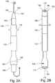
- FIGS. 2A and B show an embodiment of a cannula system 100.
- the cannula system includes a cannula 102 and a trocar 106 inserted through the lumen 104 with a puncture tip 108.
- the lumen extends between the pump-side outlet 110 and the heart-side Inlet 112.
- the inlet 112 is bounded by an inlet edge 114, wherein in the present embodiment the FIGS. 2 the inlet edge is executed plan.
- Plan here means that the inlet edge is substantially aligned in a plane perpendicular to the longitudinal axis 116 of the cannula 102.
- the cannula has a length of, for example, 50 to 70 cm between the inlet 112 and the outlet 110.
- the thickness or wall thickness of the cannula is, for example, 2 mm in the region of the inlet 112. In the region of the outlet 110, the wall thickness may be smaller, in order to simplify a connection of the outlet 110 to a pump.
- the outlet 110 is slightly widened with respect to the inlet, so as to be able to absorb the inlet of a pump easier.
- an additional adapter can be arranged in the region of the outlet 110, which simplifies connection to the pump.
- a suture ring 118 Disposed on the outside of the cannula 102 is a suture ring 118, which is connectable to a suture ring, not shown, which can be connected to the apex of the heart or is already connected to the heart when the cannula is inserted.
- the suture ring is formed, for example, flange-like and may for example consist of a felt, a fabric or of the material of the cannula shaft 120 itself or include one of these materials.
- the length of the cannula between the inlet 112 and the suture ring 118 may be for example 2 to 5 cm. This length is sufficient to place the suture ring substantially on the outside of the heart and to anchor the inlet securely inside the ventricle of the patient.
- a reinforcement 122 which is arranged in the region of the passage of the cannula through the skin and is intended to promote ingrowth of the cannula in the region of the skin. This is intended to reduce the risk of infection for the patient.
- the cannula in the FIGS. 2 is shown colorless, the cannula may be made for example of a transparent material.
- the cannula may substantially comprise a silicone shaft. Silicone is transparent here.
- a mark 124 is arranged, whose function will be discussed in more detail.
- the trocar 106 has, as already mentioned, a punctation tip 108.
- the puncturing tip extends between the inlet edge 114 and the tip 126 over a length of, for example, 3 cm.
- the puncturing tip is running of the trocar from the inlet 112 to the tip 126 toward conical or conical.
- the puncture tip has a diameter at the inlet end which is identical or slightly larger than the diameter of the cannula in the region of the inlet 112 without the inserted trocar.
- the trocar may for example consist of a biocompatible plastic and the tip may be shaped so that it is able to displace the tissue of the myocardium in the region of the apex.
- a guide wire 128 can also be seen.
- the cannula can be laid, for example, by means of a Seldinger technique.
- the guide wire is first attached to the apex and punctures it.
- the trocar 106 introduced into the cannula 102 is threaded onto the guide wire and guided to the apex. Since the apex has already been punctured by the guidewire, the puncture tip now displaces the tissue of the myocardium in the area of the apex and expands an opening until the opening has been widened to the size of the cannula. Although this also myocardial tissue is injured, the tissue is essentially displaced and can facilitate a subsequent recovery of the tissue.
- the cannula By widening the tissue, the cannula can now be advanced into the ventricle and the suture ring 118 sutured to a suture ring at the heart.
- the guide wire 128 and the trocar 106 can be pulled out of the cannula and clamped, for example, until it is connected to a pump passager.
- a mark 130 of the trocar In the inserted state of the trocar, a mark 130 of the trocar is at the same height as the mark 124 of the cannula 102.
- FIGS. 3 another cannula system 200 is shown.
- the cannula system 200 similar to the cannula system 100, has a cannula 202 with a lumen 204 around which a trocar 206 has been inserted.
- a puncture tip 208 of the trocar 206 protrudes in the inserted state from the Inlet 212 of the cannula 202 out and covers it completely.
- the inlet rim 214 in the present example is not planed but oblique, that is, the inlet rim is formed in a plane at an angle of less than 90 ° with respect to the longitudinal axis 216 of the cannula.
- the upper inlet section 217 formed between the inlet edge 214 in a connecting seam 215 is made of a material other than the cannula shaft 218.
- the upper inlet section is formed of a titanium or a titanium sleeve, which is embedded in the cannula shaft.
- the admitting can be done for example by casting or cohesive bonding.
- the metal sleeve, such as titanium, for example, may have improved biocompatible properties.
- an alternative form of marker 224 is seen, which has been brought into coincidence with an underlying marker 230 of the trocar.
- the marking here is not a pure marking formed transversely to the longitudinal axis 216 but a two-dimensional pictogram.
- the embedding of the marking can cause the puncturing tip to project through the inlet in a specific orientation and thus also to cover the inlet in an oblique embodiment of the inlet rim 214 ,
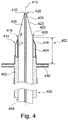
- the Fig. 4 shows a cannula system.
- the cannula system 400 includes, besides the cannula 402, a trocar 406 having a puncture tip 408 pushed through the lumen 404 of the cannula 402. Further, the trocar includes an opening 412 along the longitudinal axis 410 of the cannula (as well as the trocar) through which a guidewire is slid can implant to the cannula system using the Seldinger technique.
- the inlet 414 of the cannula 402 includes an inlet rim 416 that is substantially transverse to the longitudinal axis 410, but unlike the embodiment of FIGS. 2 has a chamfer 418. The chamfer extends over a length of about 4 mm.
- the chamfer angle ⁇ is, viewed transversely to the longitudinal axis 410, 75 °.
- the upper inlet section 422 may comprise a titanium sleeve 424 which has been chamfered, for example by means of milling or etching.
- the titanium sleeve 424 may be completely encapsulated with the silicone material of the remaining cannula 402 or may extend from the upper part of the silicone cannula.
- the chamfer angles ⁇ and ⁇ are substantially identical, they may be chosen to be different from each other.
- the puncturing tip is substantially sharper in the tip than in the region of the inlet edge.
- the inlet edge 416 is substantially 4 cm away from a sewing ring 430 formed from a textile.
- the length of the cannula 402 (and correspondingly the length of the trocar) between the inlet 416 and the outlet 432 is for example 65 cm.
- the trocar may be 10 to 20 cm longer.
- FIGS. 5 each show a cannula system in which the trocar comprises a sealing lip at the lower end of the puncturing tip.
- the cannula system 500 comprises a cannula 502, in the lumen 504 of which a trocar 506 with a punctation tip 508 is arranged.
- a sealing lip 512 At the lower edge 510 of the puncturing tip is a sealing lip 512, which covers the inlet edge 514 of the inlet 516 circumferentially.
- the lumen 506 has a diameter d l , the wall thickness d lw is 3 mm.
- the sealing lip 512 is arranged such that it extends in a flange-like manner out of the puncturing tip and projects approximately 1.5 mm beyond the inner edge 518 of the inlet rim 514.
- the inlet 516 is completely closed and foreign matter can not enter the lumen 506.
- the puncturing tip 508 has a length L PS of 30 mm.
- Inside the trocar is a lumen 522 through which a guidewire 524 may be threaded.
- the bead-shaped edge in the form of the sealing lip 512 is made of a comparatively soft material, so that the trocar can be pulled completely through the lumen 506 in the direction of the outlet, and vice versa also in the Fig.
- Not shown outlet can be inserted into the lumen 506, and can be carried out so far that the sealing lip 512 at the inlet edge 514 fully circumferentially and covers this. Since the sealing lip covers a slightly smaller area than the area defined by the outer diameter of the inlet rim 514, the outer diameter d a of the cannula is slightly larger than the diameter of the puncturing tip 508 in the region of the sealing lip 512. However, due to the angle ⁇ of the puncturing tip the myocardial tissue expanded far enough so that the cannula including the sealing lip can be inserted.
- the cannula shaft is made of silicone, for example.
- the trocar may for example be made of a biocompatible polyurethane, which is able to widen the inner wall of the silicone cannula in the region of the sealing lip, ie the trocar 506 does not change its shape, whereas the inner wall of the silicone cannula 502 when passing the trocar through the lumen 506 pushed outwards becomes.
- a mark can be used.
- a further trocar mark may be present, which marks that the trocar has been pushed too far out of the inlet and now has to be withdrawn. This can be, for example, another proximal to the mark of the FIGS. 2 or 3 be arranged trocar mark.
- FIG. 5B shown an alternative cannula system 600 which includes a cannula 602 with the cannula lumen 604 a trocar 606 with a punctation tip 608.
- This embodiment also has a sealing lip 610.
- the sealing lip is chosen such that these are essentially conforms to the shape of the puncturing tip 608 and extends it in the lower region 612.
- the sealing lip 610 is thus formed like a collar. If the trocar 606 is now not in the Fig. 5B As shown in FIG. 5, the collar 610 is applied to the outside of the trocar shaft 614, below the puncture tip 608, and thus can be easily slid through the lumen.
- the collar must first be performed fully out of the lumen 604 and the trocar then be easily pulled back towards the outlet to the now unfolded collar (as in the Fig. 5B shown), and now bring to the inlet edge 616 to cover.
- a seal of the inlet edge is ensured by the sealing lip 610.
- the cannula has a marker 618 and the trocar a first marker 620 and a second marker 622.
- the trocar is pushed through the lumen until the marker 622 is in registration with the marker 618. In this way, it is clearly visible to the operator that the collar 610 has been completely out of the lumen and thus could deploy.
- the trocar is retracted until the marker 620 is in registration with the marker 618, so that it is recognizable to the operator that the lower edge 624 of the sealing lip 610 is in contact with the inlet edge 616 and thus covers it securely, so that no tissue can accumulate in the lumen 604 of the cannula 602.
- the cannula 702 has a lumen 704 through which the in the Fig. 6 shown trocar 706 can be introduced.
- the trocar 706 has an expandable cavity 708 defined by an outer wall 710 and an inner wall 712. Schematically illustrated is a cavity inlet 714 through which a medium, such as saline or air, may be introduced into the expandable cavity 708.
- a puncturing tip 716 is formed in which the outer diameter in the region of the inlet edge 718 increases and thus covers it.
- This also causes a secure covering of the lumen 704, and no tissue can collect between the puncture tip and the cannula shaft 702.
- a traction of the trocar within the cannula to effect the cavity may include further side chambers 720 which press the trocar against the inner wall of the cannula shaft.
- the cannula After the trocar has been used to puncture the apex, the cannula has been inserted into the ventricle and the suture ring 722 has been connected to a corresponding suture ring on the heart, the medium can be drained via the lumen inlet 714, the trocar or cavity contracts together and the trocar are easily pulled out through the lumen 704. Subsequently, the cannula passager is clamped.
- FIG. 7 Based on Fig. 7 another variant of a cannula is described.
- the in the Fig. 7 The illustrated cannula 1200 includes, among other things, a pressure sensing line 1210 that extends along the cannula shaft 1102.
- the inlet configuration of the cannula is not explicitly illustrated in the figures below to address the pressure measuring line.
- the embodiments of the FIGS. 1 to 6 So can with the embodiments of the FIGS. 7 to 9 be combined.
- the pressure measuring line 1210 has a pressure measuring line inlet 1212 with a distal opening 1214 which is proximal to the distal opening 1106 but distal to the distal end of a drainage basket opening 1110.
- the drainage basket is optional.
- the pressure measuring line outlet 1216 is proximal to the proximal opening 1114 of the cannula and includes an adapter 1218 adapted for connection to an external pressure measuring system.
- the connector may be a snapfit connector or a luer lock for connection to an external pressure sensing system.
- Such adapters are well known in the art.
- the pressure measuring line 1210 extends outside of the cannula shaft 1102 and is fastened to it in a material-locking manner.
- the pressure measuring line 1210 may communicate with the outer wall of the cannula shaft 1102 either glued or welded.
- the pressure measuring line 1210 is guided through an opening 1124 or a section of the sewing ring 1122, so that it is ensured that the pressure measuring line inlet 1212 comes to rest within the ventricle.
- the distal opening 1214 of the pressure measuring conduit inlet 1212 is proximal to the distal opening 1106, as shown in FIG Fig. 8
- a distal opening 1224 of a pressure measuring conduit inlet 1222 is distal to the distal opening 1106 of the cannula.
- the distal opening of the pressure measuring lead inlet may terminate flush with the distal opening 1106 of the cannula.
- FIGS. 9A to 9C The different positions of the pressure measuring line should be shown in cross section.
- the wall of the cannula shaft 1102 is shown with the wall thickness G w .
- the wall thickness preferably has a constant thickness between 1 to 5 mm.
- the lumen 1111 of the cannula 1100 has a diameter D L of 0.3 to 2 cm.
- the pressure measuring line 1210 is disposed outside of the lumen 1111 and has a separate conduit wall 1230.
- the conduit wall may have a preferably constant wall thickness between 0.5 to 3 mm.
- the liquid that is to say in the present example blood, can enter the lumen 1232 through the distal opening, reach the adapter and thus be supplied to a pressure measurement by means of a pressure gauge in the external pressure measuring system.
- a pressure measuring sensor can be arranged within the pressure measuring line.
- This may be, for example, a membrane arranged in the pressure measuring line 1210, wherein the force acting on the membrane can be converted into a pressure.
- the deflection or the force acting on the membrane must be passed on to an external evaluation system.
- the handover can be made, for example, by means of an electrical line running inside the wall 1230.
- the actual pressure measurement will often take place in the external pressure measuring system.
- the lumen 1232 is integrated into the wall of the cannula shaft 1102.
- the pressure measuring line (similar as in the Fig. 9A separately, that is not disposed within the wall of the cannula shaft 1102, but extends within the lumen 1111. Again, the pressure measuring line may be cohesively connected to the wall of the cannula shaft 1102.
Abstract
Die vorliegende Erfindung behandelt ein Kanülensystem (500) zur Punktierung des Herzens, mit einer Kanüle (502) und einem Trokar (506), wobei die Kanüle einen Kanülenschaft mit einem herzseitigen Einlass und einem pumpenseitigen Auslass umfasst. Der Trokar besitzt einen in das Lumen der Kanüle einführbaren Trokarschaft mit einer Punktierungsspitze, wobei die Punktierungsspitze die Einlassöffnung der Kanüle vollständig überdecken kann.The present invention relates to a cannula system (500) for puncturing the heart, comprising a cannula (502) and a trocar (506), the cannula comprising a cannula shaft with a heart-side inlet and a pump-side outlet. The trocar has a trocar shaft which can be inserted into the lumen of the cannula and has a puncturing tip, the puncturing tip being able to completely cover the inlet opening of the cannula.
Description
Gegenstand der vorliegenden Anmeldung ist eine Kanüle zur Entlastung des Herzens, ein Kanülensystem, das eine derartige Kanüle sowie einen Trokar umfasst, ein Herzpumpensystem, das eine Herzpumpe sowie mindestens eine anmeldungsgemäße Kanüle umfasst, und weiterhin ein Verfahren zur Volumenentlastung eines Herzens.The present application is a cannula for relieving the heart, a cannula system comprising such a cannula and a trocar, a heart pump system comprising a heart pump and at least one cannula according to the application, and further a method for relieving the volume of a heart.
Bei akutem Linksherzversagen nach Myokardinfarkt, Dekompensation einer Herzinsuffizienz oder bei anderen Pathologien der Linksherzfunktion mit Dekompensation entsteht eine Pumpschwäche der linken Herzkammer, die unter anderem drei Effekte hat:
Erstens kommt es zu einer Dilatation des linken Ventrikels mit erhöhter Volumen- und Druckbelastung. Zweitens treten eine Unterversorgung des Körperkreislaufs mit Sauerstoff und nährstoffreichem Blut, eine Übersäuerung des Gewebes (Azidose) sowie ein drohendes Organversagen auf. Drittens treten ein Blutrückstau in der Lungenstrombahn mit einem erhöhten pulmonalen Kapillardruck sowie Lungenhochdruck und ein drohendes Lungenödem auf.In acute left heart failure after myocardial infarction, decompensation of heart failure or other pathologies of left heart function with decompensation, a pumping weakness of the left ventricle arises, which has, among other things, three effects:
First, there is a dilation of the left ventricle with increased volume and pressure loading. Second, there is a shortage of the systemic circulation with oxygen and nutrient-rich blood, acidification of the tissue (acidosis) and a threatening organ failure. Third, kick a back pressure in the pulmonary circulation with an increased pulmonary capillary pressure and pulmonary hypertension and a threatening pulmonary edema.
Beim Auftreten des Linksherzversagens werden oftmals intra-aortale Ballonpumpen (IABP), aber auch extrakorporale Herzunterstützungssysteme für eine extrakorporale Membranoxigenation (ECMO) eingesetzt. Der Zugang zu großen Körpergefäßen wird dabei zumeist über die Leistengefäße hergestellt. Hierdurch kann innerhalb weniger Minuten ein suffizienter Kreislauf im Patienten sichergestellt werden. Da bei einem akuten Linksherzversagen häufig ein Lungenstau mit Lungenödem vorliegt, wird ein Oxigenator zur verbesserten Sauerstoffzufuhr in Serie geschaltet. Jedoch ist beim Linksherzversagen das mangelnde Pumpverhalten des linken Ventrikels ursächlich, die schlechte Oxigenierung ist nur sekundär. Dennoch hat sich auch bei der Patientenkohorte mit primärem Linksherzversagen die ECMO durchgesetzt, weil sie schnell und effektiv den marginalen oder fehlenden Kreislauf wieder herstellt. Daher wurde der Begriff der extra-korporalen Lebensunterstützung (Extra Corporal Life Support; ECLS) eingeführt, um diese Patientenkohorte von der reinen ECMO-Lungen-Versagerkohorte abzugrenzen. Bei der ECMO wird eine große Körpervene als Zustrom zur Pumpe bzw. zum Oxygenator und eine große Arterie als Einstrom des Blutes in den Körperkreislauf gewählt. Aufgrund dieser Kanülierungstechnik kommt es nicht zu einer direkten Volumenentlastung des schwer kontraktionsgestörten linken Ventrikels. Somit ist eine eventuelle Verbesserung der linksventrikulären Kontraktilität kaum möglich.When left ventricular failure occurs, intra-aortic balloon pumps (IABP) are often used, as are extracorporeal cardiac support systems for extracorporeal membrane oxygenation (ECMO). Access to large body vessels is usually made via the inguinal vessels. As a result, a sufficient circulation in the patient can be ensured within a few minutes. Since pulmonary congestion with pulmonary edema is common in acute left ventricular failure, an oxygenator is connected in series for improved oxygen delivery. However, the lack of pumping behavior of the left ventricle is the cause of left heart failure, the poor oxygenation is only secondary. Nevertheless, the ECMO has also become established in the cohort of patients with primary left ventricular failure, because it quickly and effectively restores the marginal or missing circulation. Therefore, the term extra corporal life support (ECLS) was introduced to delineate this cohort of patients from the pure ECMO pulmonary failure cohort. In ECMO, a large body vein is selected as the influx to the pump or oxygenator, and a large artery as the blood inflow into the systemic circulation. Due to this cannulation technique, there is no direct volume reduction of the heavily contracted left ventricle. Thus, a possible improvement in left ventricular contractility is hardly possible.
Weitere beschrieben Verfahren zur Entlastung des linken Ventrikels, z.B. über den linken Vorhof mittels eines Katheters oder einer Atrio-Septektomie können keine effiziente Entlastung des linksventrikulären Cavums erzielen. Daher sind die Chancen, dass sich ein Patient alleine durch die ECLS in seiner linksventrikulären Kontraktilität erholt, sehr gering.Other described methods of relieving the left ventricle, e.g. Via the left atrium by means of a catheter or atrial septotomy can not achieve efficient relief of the left ventricular cavum. Therefore, the chances of a patient recovering from ECLS alone in his left ventricular contractility are very low.
Eine effektive Möglichkeit bieten jedoch linksventrikuläre Unterstützungssysteme, so genannte "Left-Ventricular Assist Devices" (LVAD). Diese sind jedoch in der Implantationstechnik komplex und werden in vielen Fällen bei einer akuten Linksherz-Dekompensation nicht sofort implantiert. Zudem kosten LVADs ein Vielfaches der oben genannten ECMO-, IABP- oder ECLS-Pumpensysteme.An effective option, however, is provided by left ventricular assist devices (LVAD). However, these are complex in the implantation technique and in many cases are not implanted immediately in acute left heart decompensation. In addition, LVADs cost many times the above-mentioned ECMO, IABP or ECLS pump systems.
Bei den linksventrikulären Unterstützungssystemen ist die Punktierung des Herzens von großer Bedeutung. Zumeist wird hier bei der Implantation der Thorax freigelegt um das Herz zum einen zu punktieren und zum anderen im Bereich der Punktierung einen Naht-Ring zur Befestigung der Pumpe am Herzen zu anzubringen.In left ventricular assist systems, puncturing of the heart is of great importance. In most cases, during implantation, the thorax is exposed here in order to puncture the heart on the one hand and, secondly, in the area of the puncture, to attach a suture ring for attaching the pump to the heart.
Aufgabe der vorliegenden Erfindung ist es, ein effizientes, leicht implantierbares System zur rasch anwendbaren und sicheren Implantation am Herzen zu schaffen, so dass es zu einer raschen Volumenentlastung des linken Ventrikels kommt und damit auch die Kontraktilität des linken Ventrikels verbessert werden kann.The object of the present invention is to provide an efficient, easily implantable system for rapidly applicable and safe implantation at the heart, so that there is a rapid volume relief of the left ventricle and thus also the contractility of the left ventricle can be improved.
Die Aufgabe wird mit Hilfe der in den Ansprüchen genannten Kanülensysteme sowie einem in Verbindung mit dem Kanülensystem ausgelegten Herzunterstützungssystem gelöst. Ferner wird ein Verfahren zur Volumenentlastung des linksseitigen Herzens offenbart.The object is achieved by means of the cannula systems mentioned in the claims as well as a cardiac support system designed in conjunction with the cannula system. Further, a method for volume relieving the left-sided heart is disclosed.
Das anmeldegemäße Kanülensystem zur Punktion des Herzens umfasst zumindest eine Kanüle und einen für diese Kanüle ausgelegten Trokar. Die Kanüle besitzt einen Kanülenschaft mit einem herzseitigen Einlass, welcher einen eine Einlassöffnung begrenzenden Einlassrand aufweist. An einem anderen Ende befindet sich ein pumpenseitiger Auslass wobei sich zwischen dem Ein- und dem Auslass ein Lumen erstreckt. Unter einem pumpenseitigen Auslass ist hierbei zu verstehen, dass der Auslass der Kanüle derart ausgebildet ist, dass dieser mit bekannten Pumpensystemen, z.B. KurzzeitZentrifugalpumpen, verbunden werden kann. Insbesondere kann dies in einigen Ausführungsformen bedeuten, dass entweder die Kanüle direkt oder über einen Konnektor an einer Pumpe angeordnet werden kann oder dass ein an der Pumpe angeordneter Konnektor direkt mit der Kanüle verbunden werden kann.The registration-based cannula system for puncturing the heart comprises at least one cannula and a trocar designed for this cannula. The cannula has a cannula shaft with a heart-side inlet which has an inlet rim defining an inlet opening. At another end is a pump-side outlet with a lumen extending between the inlet and the outlet. By a pump-side outlet, it is to be understood that the outlet of the cannula is designed to be connected to known pump systems, e.g. Short-term centrifugal pumps, can be connected. In particular, in some embodiments, this may mean that either the cannula may be attached to a pump directly or via a connector, or that a connector attached to the pump may be connected directly to the cannula.
In einigen Ausführungsbeispielen ähnelt die derartige Kanüle den Berlin Heart Excor Kanülen, insbesondere den Berlin Heart Excor Apex Kanülen. So kann die Kanüle beispielsweise aus Silikon gefertigt sein, wobei das Silikon eine Wandungsstärke zwischen 1 und 5 mm betragen kann. Ein alternatives Material ist beispielsweise Polyurethan (PU). Dabei ist das Polyurethan in einigen Ausführungsformen mit einer Beschichtung versehen, beispielsweise um die Risiken zur Thrombenbildung zu verringern.In some embodiments, such a cannula resembles the Berlin Heart Excor cannulas, particularly the Berlin Heart Excor Apex cannulas. For example, the cannula can be made of silicone, wherein the silicone can have a wall thickness of between 1 and 5 mm. An alternative material is for example polyurethane (PU). The polyurethane is in some Embodiments provided with a coating, for example, to reduce the risk of thrombus formation.
Ferner umfasst das Kanülensystem einen Trokar. Dieser Trokar besitzt einen vom Auslass des Kanülenschafts in das Lumen einführbaren Trokarschaft mit einer Punktierungsspitze. Die Punktierungsspitze ist dabei bevorzugt derart ausgebildet, dass diese einen Myokard durchstoßen kann, d.h., dass diese den Apex des Herzens im Bereich des linken Ventrikels durchstoßen kann. In einigen Ausführungsbeispielen ist die Punktierungsspitze daher kegelförmig oder annähernd kegelförmig ausgebildet. Auf diese Weise wird das Myokardgewebe nicht lediglich durchstoßen, sondern angeritzt und die Punktierungsspitze kann sich aufgrund der Kegelform langsam durch das Myokard in das linke Ventrikel schieben. Dabei wird das Gewebe des Apex schonend verdrängt. Es findet also keine Myektomie, d.h. keine Resektion von Apexgewebe, sondern lediglich eine Verdrängung des Herzgewebes statt. Dies hat beispielsweise bei Kurzzeitanwendungen den Vorteil, dass sich der Herzmuskel schneller erholen kann (auch nach einer Explantation der Kanüle). Dieser Vorteil kommt insbesondere bei pädiatrischen Anwendungen zur Geltung, da die Verdrängung des Herzmuskels (auch aufgrund der geringeren Größe des Kinderherzens) eine schnellere Erholung als nach einer Myektomie zulässt.Furthermore, the cannula system comprises a trocar. This trocar has a trocar shaft insertable into the lumen from the outlet of the cannula shaft with a punctation tip. The puncture tip is preferably designed such that it can pierce a myocardium, that is, that it can pierce the apex of the heart in the region of the left ventricle. In some embodiments, the puncturing tip is therefore conical or approximately conical in shape. In this way, the myocardial tissue is not merely punctured but scored, and the punctation tip can slowly slide through the myocardium into the left ventricle due to the conical shape. The tissue of the apex is gently displaced. So there is no myectomy, i. no resection of apex tissue, but merely a displacement of the heart tissue instead. This has the advantage, for example, in short-term applications that the heart muscle can recover faster (even after an explantation of the cannula). This advantage is particularly effective in pediatric applications, as the displacement of the heart muscle (also due to the smaller size of the baby's heart) allows a faster recovery than after a myectomy.
Der Trokarschaft ist anmeldungsgemäß länger als das Lumen der Kanüle, so dass die am Einlass des Kanülenschafts herausragende Punktierungsspitze einem aus dem Auslass hinausragenden Teil des Trokarschafts gegenüberliegt. In einer Punktierungskonfiguration ragt die Punktierungsspitze aus dem Einlass der Kanüle. Ferner besitzt der Trokarschaft einen Umfang und eine Geometrie, so dass der Trokarschaft oder die Punktierungsspitze die Einlassöffnung vollständig überdecken. Dies bedeutet im Wesentlichen, dass der Trokarschaft oder die Punktierungsspitze den Einlass vollständig abdichten, so dass bei in der Punktierungskonfiguration eingeführten Trokar keinerlei Flüssigkeit durch den Einlass des Kanülenschafts in das Lumen treten kann bzw. sich beim gemeinsamen Einführen der Kanüle und dem in der Kanüle angeordneten Trokar sich kein Apexgewebe in einem Hohlraum zwischen dem Trokar und der Kanüle ansammeln kann. Somit wird die Thrombengefahr zu einem späteren Zeitpunkt gegenüber anderen Punktierungsverfahren erhöht. Aufgrund der hier offenbarten Konfiguration der Kanüle und des Trokars ist es möglich, die Kanüle ohne Öffnung des Thorax mit dem Herzen zu verbinden. Hierzu wird zunächst der Trokar in die Kanüle eingeführt und die Punktionskonfiguration geschoben. Anschließend wird das Kanülensystem beispielsweise unterhalb des Rippenbogens oder durch den Interkostalraum zum Apex vorgeschoben, wobei nach Erreichen des richtigen Orts am Herzen die Punktierungsspitze weiter an dem Apex vorgeschoben wird und in das linke Ventrikel eindringt. Das die Punktierungsspitze am größten Umfang im Wesentlichen mit dem Umfang der Innenwand des Einlasses übereinstimmt und die Wandstärke der Kanüle vergleichsweise gering ist gegenüber dem Durchmesser des Lumens der Kanüle kann der Einlass der Kanüle selbst in Verbindung mit dem Trokar in dem Apex durch den Myokard in das linke Ventrikel geschoben werden.The trocar shaft is reported to be longer than the lumen of the cannula, such that the puncture tip protruding at the inlet of the cannula shaft faces a portion of the trocar shaft protruding from the outlet. In a puncturing configuration, the puncture tip protrudes from the inlet of the cannula. Further, the trocar shaft has a circumference and a geometry such that the trocar shaft or puncturing tip completely covers the inlet opening. Essentially, this means that the trocar shaft or puncture tip completely seals the inlet so that no fluid can pass through the inlet of the cannula shaft into the lumen when the trocar is inserted in the puncturing configuration or when the cannula is inserted together and within the cannula Trocar can accumulate no apex tissue in a cavity between the trocar and the cannula. Thus, the risk of thrombosis is increased at a later time compared to other puncturing procedures. Due to the configuration of the cannula and the trocar disclosed herein, it is possible to connect the cannula to the heart without opening the thorax. First, the trocar is inserted into the cannula and the puncture configuration is pushed. Subsequently, the cannula system is advanced, for example, below the costal arch or through the intercostal space to the apex, upon reaching the correct location on the heart, the puncture tip is advanced further to the apex and enters the left ventricle. Since the puncture tip at the greatest circumference substantially coincides with the circumference of the inner wall of the inlet and the wall thickness of the cannula is comparatively small relative to the diameter of the lumen of the cannula, the inlet of the cannula itself in conjunction with the trocar in the apex can penetrate into the myocardium through the myocardium to be pushed left ventricle.
Weitere Ausführungen und Ausführungsbeispiele können den nachfolgenden Beschreibungen und Figurenbeschreibungen entnommen werden.Further embodiments and exemplary embodiments can be taken from the following descriptions and description of the figures.
Es zeigen:
- Fig. 1
- eine schematische Darstellung eines Kanülen- bzw. Pumpensystems;
- Fign. 2A und
- B eine Ausführungsform eines Kanülensystems mit planarem Einlassrand;
- Fign. 3A und
- B eine Ausführungsform eines Kanülensystems mit schrägem Einlassrand;
- Fig. 4
- eine Ausführungsform eines Kanülensystems mit gefastem Einlassrand; und
- Figs. 5A und B
- verschiedene Ausführungsformen eines Kanülensystems mit Dichtlippe;
- Fig. 6
- eine Ausführungsform eines Kanülensystems mit einem expandierbaren Hohlraum;
- Fig. 7
- weitere Ausführungsform einer Kanüle;
- Fig. 8
- weitere Ausführungsform einer Kanüle;
- Fig. 9a bis 9c
- Ausführungsform einer Anordnung einer Druckmessleitung.
- Fig. 1
- a schematic representation of a cannula or pump system;
- FIGS. 2A and
- B shows an embodiment of a cannula system with a planar inlet edge;
- FIGS. 3A and
- B is an embodiment of a cannula system with oblique inlet edge;
- Fig. 4
- an embodiment of a bevelled inlet edge cannula system; and
- Figs. 5A and B
- various embodiments of a cannula system with sealing lip;
- Fig. 6
- an embodiment of a cannula system with an expandable cavity;
- Fig. 7
- another embodiment of a cannula;
- Fig. 8
- another embodiment of a cannula;
- Fig. 9a to 9c
- Embodiment of an arrangement of a pressure measuring line.
Nachfolgend werden zunächst weitere Ausführungen zum Verfahren der Volumenentlastung und weitere Ausführungsformen der Erfindung beschrieben.Hereinafter, further embodiments of the method of volume relief and further embodiments of the invention will be described.
Beim anmeldungsgemäßen Verfahren zur Druckentlastung können die hier beschriebenen Kanülensysteme verwendet werden. Nachstehend wird beispielhaft ein Punktions- bzw. Kanülierungsverfahren während der Implantation, sowie ein Explantationsverfahren beschrieben.In the method according to the invention for pressure relief, the cannula systems described here can be used. Hereinafter, a puncture or Kanülierungsverfahren during implantation, as well as an explant method will be described by way of example.
Um eine rasche Entlastung der linken Herzkammer zu erreichen, wird mithilfe eines minimal invasiven Zugangs über einer antero-laterale Mini-Thorakotomie die Spitze des Linken Ventrikels (Apex) freigelegt, unterhalb des Rippenbogens oder durch den Interkostalraum (4. oder 5. ICR). (Dies entspricht einem operativen Zugang wie bei einer transapikalen TAVR). Die Kanüle wird mittels einer Seldinger-Technik platziert. Hierbei wird zunächst der Führungsdraht mittels einer Punktionsnadel am Apex angesetzt und durchstößt diesen. Unter radiologischer Durchleuchtung wird der Draht (Pigtail) im LV platziert. Anschließend werden der in die Kanüle eingeführte Trokar auf den Führungsdraht aufgefädelt und zum Apex geführt. Da der Apex bereits durch den Führungsdraht punktiert wurde, verdrängt die Punktierungsspitze nunmehr das Gewebe des Myokards im Bereich des Apex und weitet eine Öffnung auf bis die Öffnung auf die Größe der Kanüle geweitet wurde. Eine Entfernung von vitalem Herzmuskelgewebe (Myektomie) ist somit nicht notwendig. Obgleich hierbei auch Myokardgewebe verletzt wird, wird das Gewebe jedoch im Wesentlichen schonend verdrängt und kann eine spätere Erholung des Gewebes vereinfachen. Durch die Aufweitung des Gewebes kann die Kanüle nunmehr in den Ventrikel vorgeschoben werden bis zum Fixierungsrand (Nahtring), der dann durch Einzelknopfnähte mit dem Herzen verbunden wird. Nachdem die am Ventrikel vorverlegten Nähte mit der Kanüle fixiert worden sind und diese mit dem Herzen selbst blutdicht verbunden ist, kann der Trokar zurückgezogen und somit die Kanüle entlüftet werden, um anschließend passager geklemmt zu werden. Optional können weitere fortlaufende Nähte am Nahtring zur besseren Blutdichtigkeit gesetzt werden.To achieve rapid relief of the left ventricle, the tip of the left ventricle (apex) is exposed using a minimally invasive approach via an antero-lateral mini-thoracotomy, below the costal arch, or through the intercostal space (4th or 5th ICR). (This corresponds to an operational access like a transapical TAVR). The cannula is placed using a Seldinger technique. In this case, the guidewire is first attached to the apex by means of a puncture needle and punctures it. Under radiographic examination, the wire (pigtail) is placed in the LV. Subsequently, the introduced into the cannula trocar are threaded onto the guide wire and guided to the apex. Since the apex has already been punctured by the guidewire, the puncture tip now displaces the tissue of the myocardium in the area of the apex and expands an opening until the opening has been widened to the size of the cannula. Removal of vital myocardial tissue (myectomy) is therefore not necessary. Although this also myocardial tissue is injured, the tissue is essentially gently displaced and can facilitate a subsequent recovery of the tissue. Due to the widening of the tissue, the cannula can now be advanced into the ventricle to the fixing edge (sewing ring), which is then connected by single button seams with the heart. After the ventricle vorverlegt seams have been fixed with the cannula and it is blood-tightly connected to the heart itself, can the trocar is withdrawn and thus the cannula are vented to be subsequently clamped passager. Optionally, further continuous seams can be placed on the sewing ring for better blood-tightness.
In weiteren Ausführungsbeispielen können beidseitig der Kanüle Distanzhalter bzw. ein oder mehrere Distanzhalter in den Zwischenrippenraum bzw. Interkostalraum eingebracht werden, um ein eventuelles Abknicken oder eine Kompression der Kanüle durch die Rippen zu verhindern. Alternativ kann die Kanüle mit Wandverstärkungen ausgestattet werden, die eine Kompression durch Rippen verhindert. Anschließend kann die Kanüle entlüftet und beispielsweise mit einer handelsüblichen zentrifugalen Kurzzeitblutpumpe, wie z.B. eine Rota-flow von Marquet, eine Hemopump von Sorin, eine Deltasteam DP3 von Medos/Xenios, verbunden werden. Jedoch kann das System auch beispielsweise mit einer parakorporalen Verdrängerpumpe, wie Berlin Heart Excor, verbunden werden.In further exemplary embodiments, the cannula spacers or one or more spacers can be introduced into the intercostal space or intercostal space on both sides in order to prevent possible kinking or compression of the cannula by the ribs. Alternatively, the cannula can be equipped with wall reinforcements that prevent compression by ribs. Subsequently, the cannula may be vented and, for example, with a commercial centrifugal short-term blood pump, such as. a rota-flow from Marquet, a hemopump from Sorin, a delta team DP3 from Medos / Xenios. However, the system may also be connected, for example, to a paracorporal positive displacement pump, such as Berlin Heart Excor.
Die für das Pumpensystem ausgewählte Pumpe wird ferner mit einer weiteren Kanüle, der sogenannten arteriellen Ausflusskanüle, verbunden. Diese arterielle Kanüle kann entweder perkutan oder chirurgisch an die große Leistenarterie oder chirurgisch an die Arteria Subclava angeschlossen werden. Ferner kann in einigen Ausführungsbeispielen bei einem Patienten, sofern er bereits wegen seiner schlechten Kreislaufsituation an eine ECMO/ECLS angeschlossen ist, zunächst der arterielle Zugang des ECMO/ECLS als Ausflussort benutzt werden, und der venöse Zugang wird nach erfolgreicher Etablierung und Kanülierung des Apex mit dem Kanülensystem entfernt. So kann das Blut aus dem linken Ventrikel über das etablierte System geleitet werden und somit eine direkte Entlastung des linken Ventrikels erreicht (Apexkanüle) und eine Unterstützung des Kreislaufsystems (arterielle Ausflusskanüle) erzielt werden. Somit stellt die Kanüle zusammen mit der Pumpe und der Ausflusskanüle ein Kurzzeit-VAD-System dar, mit einer möglichen Unterstützungszeit bis zu 30 Tage (in Abhängigkeit von der verwendeten Pumpe).The pump selected for the pump system is further connected to another cannula, the so-called arterial outflow cannula. This arterial cannula can be attached either percutaneously or surgically to the great inguinal artery or surgically to the subclavian artery. Further, in some embodiments in a patient, if already connected to an ECMO / ECLS because of its poor circulatory situation, first the arterial access of the ECMO / ECLS may be used as the outflow site, and the venous access will follow upon successful establishment and cannulation of the apex removed from the cannula system. Thus, the blood from the left ventricle can be directed through the established system, thus achieving direct relief of the left ventricle (apex cannula) and support of the circulatory system (arterial outflow cannula). Thus, together with the pump and the outflow cannula, the cannula represents a short-term VAD system, with a possible support time of up to 30 days (depending on the pump used).
Um die Therapie optimal steuern zu können kann in die Kanüle eine zusätzliche Druckmessleitung integriert sein. An der Spitze der Kanüle mündet diese Druckmessleitung im Ventrikel. Diese Druckmessleitung wird dann auslassseitig mit einem handelsüblichen Druckaufnehmersystem verbunden und kann so an einen üblichen Monitor zur hämodynamischen Überwachung angeschlossen werden. Diese Druckmessung kann kontinuierlich die Messung des LVEDP (linksventrikulären Enddiastolischen Druck) anzeigen. Dies ist kann beispielsweise helfen, die optimale Entlastung des linken Ventrikels zu steuern, z. B. Anpassung (Erhöhung oder Erniedrigung der geförderten Menge Blutvolumen pro Minute). Insbesondere spielt dies eine Rolle bei der Entwöhnung des Patienten vom System, nachdem sich das Herz von der Herzschwäche erholt hat.In order to be able to optimally control the therapy, an additional pressure measuring line can be integrated in the cannula. At the tip of the cannula, this pressure measuring line opens into the ventricle. This pressure measuring line is then connected to the outlet side with a commercially available pressure transducer system and can connected to a standard hemodynamic monitor. This pressure measurement can continuously display the measurement of LVEDP (left ventricular end-diastolic pressure). This can, for example, help to control optimal relief of the left ventricle, e.g. B. Adjustment (increase or decrease in the delivered amount of blood volume per minute). In particular, this plays a role in weaning the patient from the system after the heart has recovered from the heart failure.
Bei einer Erholung der Herzfunktion ist es notwendig den Blutfluss durch die Kanüle bzw. Pumpe schrittweise zu reduzieren. Bei der Reduzierung des Flusses wird im linken Ventrikel mehr Blutvolumen zurück belassen, um zu schauen, ob das Herz die Mehrbelastung schafft ohne dass der Füllungsdruck der linken Herzkammer (LVEDP= left ventricular end diastolic pressure) steigt. Um die Kontraktionsleistung des Herzens unter der Mehrbelastung einschätzen zu können wird also bevorzugt der LVEDP herangezogen. Hat sich die Herzfunktion erholt, kann die Apex-Kanüle und damit das VAD- System wieder über den minimal invasiven Zugang entfernt werden.When recovering the heart function, it is necessary to gradually reduce the blood flow through the cannula or pump. In reducing the flow, more blood volume is left in the left ventricle to see if the heart is creating the extra burden without increasing left ventricular end diastolic pressure (LVEDP). In order to be able to estimate the contraction power of the heart under the additional load, the LVEDP is therefore preferably used. Once the cardiac function has recovered, the Apex cannula and thus the VAD system can be removed again via the minimally invasive approach.
Hierfür wird der Apexbereich erneut zugänglich gemacht. Die Kanüle wird geklemmt um keinen Blutfluss mehr über das System zu haben. Da keine Myektomie erfolgt ist, kann über bereits bei der Implantation vorgelegte Filze eine Tabaksbeutel-Naht platziert werden, welche dann die Eintritts-Stelle der Kanüle am Apex während und nach Herausziehen der Kanüle verschließt, indem das umliegende Herzmuskelgewebe zusammengezogen wird. Zusätzlich wird die Kanülierungsstelle mit filzarmierten Nähten gesichert.For this purpose, the apex area is made accessible again. The cannula is clamped to stop blood flow through the system. Since no myectomy has occurred, a tobacco pouch suture can be placed over felts already placed at implantation, which then closes the cannula's entry site to the apex during and after withdrawal of the cannula by contracting the surrounding myocardial tissue. In addition, the cannulation site is secured with felt-reinforced sutures.
In einer Ausführungsform umfasst der Trokar eine umlaufende Dichtlippe, welche vorzugsweise am Übergang zwischen der Punktierungsspitze und dem eigentlichen Trokarschaft angeordnet ist. Diese Dichtlippe ist derart angeordnet, dass sie den Einlassrand zumindest teilweise überdeckt, vorzugsweise den Einlassrand vollständig umläuft und überdeckt. Eine zwischen der Punktierungsspitze und dem Trokarschaft angeordnete Dichtlippe hat unter anderem den Vorteil, dass beim Ausführen der Dichtlippe aus dem Kanülenschaft ein taktiles Feedback erzeugt wird und der Trokar sich deutlich leichter durch das Lumen schieben lässt nachdem die Dichtlippe am Einlass der Kanüle ausgetreten ist. Beim daraufhin folgenden Zurückziehen des Trokarschafts dichtet die Dichtlippe die Einlassöffnung vollständig ab, so dass die Einlassöffnung vollständig überdeckt wird, auch wenn der Trokarschaft einen Umfang besitzt, welcher geringer ist als der Umfang der Innenseite des Lumens. Die Dichtlippe kann dabei in verschiedenen Ausführungsformen unterschiedlich gestaltet sein.In one embodiment, the trocar comprises a circumferential sealing lip, which is preferably arranged at the transition between the puncturing tip and the actual trocar shaft. This sealing lip is arranged such that it at least partially covers the inlet edge, preferably completely surrounds and covers the inlet edge. One of the advantages of the sealing lip disposed between the puncture tip and the trocar shaft is that a tactile feedback is generated when the sealing lip is carried out of the cannula shaft and the trocar can be pushed much more easily through the lumen after the sealing lip emerges at the inlet of the cannula is. In the subsequent retraction of the trocar shaft, the sealing lip completely seals the inlet opening, so that the inlet opening is completely covered, even if the trocar shaft has a circumference which is smaller than the circumference of the inside of the lumen. The sealing lip can be designed differently in various embodiments.
So kann die Dichtlippe beispielsweise kragen- oder flanschförmig am Übergang zwischen der Punktierungsspitze und dem Trokarschaft angeordnet sein. Die Dichtlippe kann jedoch auch eine Verlängerung der Punktierungsspitze bilden, so dass die Dichtlippen eine im Wesentlichen kegelförmige Gestalt der Punktierungsspitze verlängern, d.h. in Richtung des Auslasses und nach Außen hin leicht abstehen.For example, the sealing lip may be arranged in the shape of a collar or flange at the transition between the puncturing tip and the trocar shaft. However, the sealing lip may also form an extension of the puncturing tip so that the sealing lips extend a substantially conical shape of the puncturing tip, i. slightly protruding towards the outlet and outwards.
In einer weiteren Ausführungsform ist der Einlassrand angefast und weist in axialer Richtung zur Einlassöffnung hin eine Fase auf. Diese Ausführungsform ist insbesondere dann vorteilhaft, wenn die Punktierungsspitze (oder auch Punktionsspitze) bündig mit dem Einlassrand abschließt. Hierzu kann in einigen Ausführungsbeispielen die Punktierungsspitze ebenfalls angefast sein und ein Fasenwinkel der Punktierungsspitze und ein Fasenwinkel der Fase des Einlassrandes um weniger als 30° voneinander abweichen, insbesondere um weniger als 20° oder 10° voneinander abweichen und insbesondere im Wesentlichen gleich sind. Mit anderen Worten ist bei ähnlichem Fasenwinkel der Einlassrand als Verlängerung der Punktierungsspitze des Trokars zu sehen. Hierdurch wird ein besonders gewebeschonendes Einführen der Kanüle in den Apex ermöglicht. Als Fasenwinkel bieten sich beispielsweise Winkel größer als 30°, gemessen in der Ebene quer zur Längsachse der Kanüle, an, vorzugsweise Winkel von mehr als 45°, besonders vorzugsweise größer als 60°. Auf diese Weise wird ein schonendes Einführen des Kanülensystems in den linken Ventrikel gewährleistet.In a further embodiment, the inlet edge is chamfered and has a chamfer in the axial direction towards the inlet opening. This embodiment is particularly advantageous when the puncture tip (or puncture tip) is flush with the inlet edge. For this purpose, in some embodiments, the puncturing tip may also be chamfered and a chamfer angle of the puncturing tip and a chamfer angle of the chamfer of the inlet edge to each other by less than 30 °, in particular by less than 20 ° or 10 ° to each other and in particular are substantially equal. In other words, with a similar chamfer angle, the inlet edge can be seen as an extension of the puncture tip of the trocar. This allows a particularly tissue-gentle insertion of the cannula into the apex. As a chamfer angle, for example, angles greater than 30 °, measured in the plane transverse to the longitudinal axis of the cannula, offer, preferably angles of more than 45 °, particularly preferably greater than 60 °. In this way, a gentle insertion of the cannula system is ensured in the left ventricle.
In einer weiteren Ausführungsform weist die Punktierungsspitze des Trokars einen expandierbaren Hohlraum auf, und die Punktierungsspitze überdeckt die Einlassöffnung dann, wenn der Hohlraum in einem expandierten Zustand ist. Hierbei ist es in einigen Ausführungsformen vorgesehen, dass die Punktierungsspitze den Einlassrand im expandierten Zustand des Hohlraums zumindest teilweise, vorzugsweise vollständig überdeckt. Hierbei wird, wie in den anderen Ausführungsbeispielen ausgeführt, eine gute Abdichtung zwischen dem Trokar und der Kanüle erreicht und zugleich ein verbessertes Einführen des Kanülensystems in das linke Ventrikel sichergestellt.In another embodiment, the puncture tip of the trocar has an expandable cavity, and the puncture tip covers the inlet opening when the cavity is in an expanded state. In this case, it is provided in some embodiments that the puncturing tip at least the inlet edge in the expanded state of the cavity partially, preferably completely covered. In this case, as stated in the other embodiments, a good seal between the trocar and the cannula is achieved while ensuring an improved insertion of the cannula system into the left ventricle.
Um den Hohlraum zu expandieren, kann vorgesehen sein, dass am auslassseitigen Ende des Trokars ein Medieneinlass vorhanden ist, über welchen ein Medium in den Hohlraum gefüllt werden kann und diesen expandiert. Als Medien können beispielsweise Kochsalzlösungen infrage kommen oder in anderen Ausführungsbeispielen auch Luft.In order to expand the cavity, provision may be made for a media inlet to be present at the outlet end of the trocar, via which medium a medium can be filled into the cavity and expanded. For example, saline solutions can be used as media or air in other embodiments.
In vielen Fällen wird der Trokar bzw. die Punktierungsspitze des Trokars ein hartes Material, wie beispielsweise Stahl, oder einen harten bioverträglichen Kunststoff umfassen. Es ist jedoch auch vorgesehen, dass der Trokarschaft genügend Flexibilität besitzt, um durch den Interkostalraum an den linken Apex geführt zu werden. Hierbei kann der Trokar beispielsweise einen Mantel aus einem flexiblen biokompatiblen Kunststoff besitzen.In many cases, the trocar or puncture tip of the trocar will comprise a hard material, such as steel, or a tough biocompatible plastic. However, it is also envisaged that the trocar shaft will have sufficient flexibility to pass through the intercostal space to the left apex. In this case, the trocar may for example have a jacket made of a flexible biocompatible plastic.
In einigen Ausführungsbeispielen ist vorgesehen, dass an der Außenseite des Kanülenschafts in der Nähe des Einlasses ein Naht-Ring zur Verbindung der Kanüle mit dem Herzen angeordnet ist. Dabei ist Naht-Ring beispielsweise stoffschlüssig mit dem Kanülenschaft verbunden. Der Naht-Ring kann beispielsweise aus einem Filz bestehen oder diesen umfassen, so dass das Vernähen auf einfache Art und Weise möglich wird.In some embodiments, it is provided that a suture ring for connecting the cannula to the heart is arranged on the outside of the cannula shaft in the vicinity of the inlet. In this case, the suture ring is, for example, firmly bonded to the cannula shaft. The suture ring may for example consist of or comprise a felt, so that the sewing is possible in a simple manner.
In einer weiteren Ausführungsform ist am Trokarschaft eine Trokarmarkierung vorgesehen, welche mit einer an der Kanüle angeordneten Kanülenmarkierung korrespondierend angeordnet werden kann. Das heißt, dass die Trokarmarkierung die Kanülenmarkierung beispielsweise in Deckung oder auf dieselbe Höhe (d.h. quer zur Längsachse des Lumens) angeordnet werden können. Diese Markierungen können derart angeordnet sein, dass anhand eines Indeckungbringens der Markierungen erkennbar ist, wenn die Punktierungsspitze des Trokars die Einlassöffnung überdeckt. Insbesondere kann dies in den Ausführungsbeispielen, in welchen eine Dichtlippe oder eine zum Fasenwinkel der Punktierungsspitze korrespondierende Anfasung des Einlassrandes vorgesehen ist, diejenige Stellung gekennzeichnet werden, in welcher die Punktierungsspitze bündig mit dem Einlassrand abschließt bzw. in welcher die Dichtlippe an bzw. auf dem Einlassrand anliegt und das Lumen der Kanüle abdichtet.In a further embodiment, a trocar marking is provided on the trocar shaft, which can be arranged correspondingly with a cannula marking arranged on the cannula. That is, the trocar marker may be placed in alignment with the cannula marker, for example, at or at the same height (ie, transverse to the longitudinal axis of the lumen). These markings can be arranged in such a way that the markings can be identified by means of covering the markings when the puncturing tip of the trocar covers the inlet opening. In particular, in the exemplary embodiments in which a sealing lip or a chamfering of the inlet edge corresponding to the chamfer angle of the puncturing tip is provided, this position can be characterized which terminates the puncturing tip flush with the inlet edge or in which the sealing lip rests against or on the inlet edge and seals the lumen of the cannula.
In einer weiteren Ausführungsform ist eine weitere Trokarmarkierung vorgesehen, welche in Bezug auf die Längsachse des Trokarschafts und gegenüber der ersten Trokarmarkierung weiter auslassseitig angeordnet ist. Hierdurch kann erkennt werden, dass, wenn die weitere Trokarmarkierung mit der Kanülenmarkierung in Deckung gebracht wurde, erkennbar ist, dass der Trokar nunmehr zurück in Richtung des Auslasses gezogen werden muss, um eine gute Abdichtung der Einlassöffnung mittels der Punktierungsspitze bzw. des Trokarschafts zu bewerkstelligen.In a further embodiment, a further trocar mark is provided, which is arranged on the outlet side with respect to the longitudinal axis of the trocar shaft and with respect to the first trocar mark. In this way, it can be seen that, when the further trocar mark has been brought into coincidence with the cannula marking, it can be seen that the trocar must now be pulled back towards the outlet in order to achieve a good seal of the inlet opening by means of the puncturing tip or trocar shaft ,
In einigen Ausführungsbeispielen kann vorgesehen sein, dass die Trokarmarkierung des Trokar ein aus dem Trokarschaft herausragender Anschlag ist und die Kanülenmarkierung entweder ein Auslassrand des Auslasses des Kanülenschafts ist oder im Bereich des Auslasses einen Stopp für den Anschlag bereitstellt.In some embodiments, it may be provided that the trocar trocar mark is an abutment protruding from the trocar shaft and that the cannula marker is either an outlet edge of the outlet of the cannula shaft or provides a stop for abutment in the region of the outlet.
In einer weiteren Ausführungsform ist vorgesehen, dass im Bereich des Einlassrandes der Kanüle eine Metallhülse oder eine Verbundwerkstoffhülse in den Kanülenschaft eingelassen ist. In einigen Ausführungsformen kann die Metallhülse bzw. die Verbundwerkstoffhülse derart in den Kanülenschaft eingelassen sein, dass diese aus dem Silikon- bzw. Kunststoffmantel der Kanüle herausragt und die unbedeckte Metall- bzw. Verbundwerkstoffhülse den Einlassrand bildet. In anderen Ausführungsbeispielen kann vorgesehen sein, dass die Metallhülse oder die Verbundwerkstoffhülse vollständig in den Kanülenschaft eingelassen sind und zumindest durch eine dünne Materialschicht des Kanülenwerkstoffs überdeckt sind. In dieser Ausführungsform wird zum einen eine gute Biokompatibilität aufgrund des Werkstoffs des Kanülenschafts gewährleistet und zum anderen eine entsprechende Versteifung des Einlassrandes gewährleistet, welche beim Einführen des Kanülensystems in den linken Ventrikel vorteilhaft sein kann.In a further embodiment it is provided that in the region of the inlet edge of the cannula a metal sleeve or a composite sleeve is embedded in the cannula shaft. In some embodiments, the metal sleeve or composite sleeve may be recessed into the cannula shaft such that it protrudes from the silicone sheath of the cannula and the uncovered metal sheath forms the inlet edge. In other embodiments it can be provided that the metal sleeve or the composite sleeve are completely embedded in the cannula shaft and are at least covered by a thin layer of material of the cannula material. In this embodiment, a good biocompatibility is ensured on the one hand due to the material of the cannula shaft and on the other hand ensures a corresponding stiffening of the inlet edge, which may be advantageous during insertion of the cannula system in the left ventricle.
Wie bereits erwähnt, umfasst das Kanülensystem alternativ oder zusätzlich zu den vorbeschriebenen Merkmalen eine Druckmessleitung, welche am Kanülenschaft, im Lumen des Kanülenschafts, oder innerhalb der Wand des Kanülenschafts geführt wird. Beispiele, wie eine Druckmessleitung an der Kanüle angeordnet wird, lassen sich beispielsweise der internationalen Patentanmeldung
Alternativ zur oder in Kombination mit der Druckmessleitung kann in der Nähe des Einlasses der Kanüle ein Drucksensor, wie beispielsweise ein mechanisch-elektromagnetischer Sensor, angeordnet sein. Auch ein mit einer Membran versehener Drucksensor kann am Einlass der Kanüle angeordnet werden.
Sollte nach der Implantation des hier vorgestellten Kanülen- bzw. Pumpensystems immer noch ein Sauerstoffproblem vorliegen, so kann ein Oxygenator seriell in die Ausflusskanüle hineingeschaltet werden. Weitere Ausführungsformen und Ergänzungen zum hier vorgestellten Kanülensystem ergeben sich aus den nachfolgenden Ausführungsbeispielen und den Ansprüchen.As an alternative to or in combination with the pressure measuring line, a pressure sensor, such as a mechanical-electromagnetic sensor, may be arranged in the vicinity of the inlet of the cannula. Also one with one Membrane provided pressure sensor can be placed at the inlet of the cannula.
Should there still be an oxygen problem after implantation of the cannula or pump system presented here, then an oxygenator can be serially switched into the outflow cannula. Further embodiments and additions to the cannula system presented here emerge from the following exemplary embodiments and the claims.
Anhand der
In der
Die
Der Trokar 106 weist, wie bereits erwähnt, eine Punktierungsspitze 108 auf. Die Punktierungsspitze erstreckt sich zwischen dem Einlassrand 114 und der Spitze 126 über eine Länge von beispielsweise 3 cm. Dabei läuft die Punktierungsspitze des Trokars vom Einlass 112 zur Spitze 126 hin konisch oder kegelförmig zu. Die Punktierungsspitze weist am einlassseitigen Ende einen Durchmesser auf, welcher identisch oder leicht größer als der Durchmesser der Kanüle im Bereich des Einlasses 112 ohne den eingeführten Trokar ist. Im vorliegenden Beispiel kann der Trokar beispielsweise aus einem biokompatiblen Kunststoff bestehen und die Spitze kann dabei derart geformt sein, dass diese das Gewebe des Myokards im Bereich des Apex zu verdrängen vermag. Im vorliegenden Beispiel ist ferner ein Führungsdraht 128 zu erkennen. Die Kanüle kann beispielsweise mittels einer Seldinger-Technik verlegt werden. Hierbei wird zunächst der Führungsdraht am Apex angesetzt und durchstößt diesen, Anschließend werden der in die Kanüle 102 eingeführte Trokar 106 auf den Führungsdraht aufgefädelt und zum Apex geführt. Da der Apex bereits durch den Führungsdraht punktiert wurde, verdrängt die Punktierungsspitze nunmehr das Gewebe des Myokards im Bereich des Apex und weitet eine Öffnung auf bis die Öffnung auf die Größe der Kanüle geweitet wurde. Obgleich hierbei auch Myokardgewebe verletzt wird, wird das Gewebe jedoch im Wesentlichen verdrängt und kann eine spätere Erholung des Gewebes vereinfachen. Durch die Aufweitung des Gewebes kann die Kanüle nunmehr in den Ventrikel vorgeschoben werden und der Naht-Ring 118 mit einem am Herzen angeordneten Naht-Ring vernäht werden. Nach erfolgter Befestigung der Kanüle am Herzen können der Führungsdraht 128 und der Trokar 106 aus der Kanüle gezogen werden und diese beispielsweise bis zum Anschluss an eine Pumpe passager geklemmt werden. Im eingeführten Zustand des Trokars liegt eine Markierung 130 des Trokars auf derselben Höhe wie die Markierung 124 der Kanüle 102. Hierdurch kann der Kardiologe von außen prüfen, ob der Trokar derart weit in die Kanüle geschoben worden ist, dass die Punktierungsspitze vollständig aus dem Einlass ragt und der Trokarschaft bzw. das auslassseitige Ende der Punktierungsspitze mit dem Einlass bzw. dem Einlassrand abschließt. Da die Punktierungsspitze 108 nunmehr bündig mit dem Einlass 112 abschließt, wird das Einschieben der Kanüle in den Ventrikel gegenüber bestehenden Verfahren deutlich vereinfacht.The
In den
Auch die
Die
Das Kanülensystem 500 umfasst eine Kanüle 502, in dessen Lumen 504 ein Trokar 506 mit einer Punktierungsspitze 508 angeordnet ist. Am unteren Rand 510 der Punktierungsspitze befindet sich eine Dichtlippe 512, welche den Einlassrand 514 des Einlasses 516 umlaufend überdeckt. Das Lumen 506 weist einen Durchmesser dl auf, die Wandstärke dlw beträgt 3 mm. Am unteren Ende 510 der Punktierungsspitze ist die Dichtlippe 512 derart angeordnet, dass diese sich flanschartig aus der Punktierungsspitze heraus erstreckt und ca. 1,5 mm über den inneren Rand 518 des Einlassrandes 514 hinausragt. Hierdurch wird der Einlass 516 vollumfänglich verschlossen und Fremdkörper können nicht in das Lumen 506 eindringen. Die Punktierungsspitze 508 weist eine Länge LPS von 30 mm auf. Die Punktierungsspitze 508 läuft dabei unter einem Winkel α = 80° vom unteren Ende 510 der Punktierungsspitze bis zum oberen Ende 520 konisch zu. Im Inneren des Trokars befindet sich ein Lumen 522, durch welches ein Führungsdraht 524 gefädelt sein kann. Der wulstförmige Rand in Form der Dichtlippe 512 besteht aus einem vergleichsweise weichen Material, so dass der Trokar vollständig durch das Lumen 506 in Richtung des Auslasses gezogen werden kann, und umgekehrt auch vom in der
In der
In der
Nachdem der Trokar zum Punktieren des Apex verwendet, die Kanüle in den Ventrikel eingeführt und der Naht-Ring 722 mit einem entsprechenden Naht-Ring am Herzen verbunden wurde, kann über den Hohlraumeinlass 714 das Medium abgelassen werden, der Trokar bzw. der Hohlraum zieht sich zusammen und der Trokar auf einfache Art und Weise durch das Lumen 704 herausgezogen werden. Anschließend wird die Kanüle passager geklemmt.After the trocar has been used to puncture the apex, the cannula has been inserted into the ventricle and the
Anhand der
Die Druckmessleitung 1210 besitzt einen Druckmessleitungseinlass 1212 mit einer distalen Öffnung 1214, welcher proximal der distalen Öffnung 1106, jedoch distal des distalen Endes einer Drainagekorböffnung 1110 liegt. Der Drainagekorb ist optional. Der Druckmessleitungsauslass 1216 liegt proximal der proximalen Öffnung 1114 der Kanüle und umfasst einen Adapter 1218, welcher zum Anschluss an ein externes Druckmesssystem ausgebildet ist. Beispielsweise kann es sich bei dem Anschluss um einen Snapfit-Connector oder einen Luerverschluss zum Anschluss an ein externes Druckmesssystem handeln. Derartige Adapter sind im Stand der Technik hinlänglich bekannt. Mittels der Druckmessleitung 1210, welche in die Kanüle 1200 integriert ist, wird erreicht, dass zu jedem Zeitpunkt der Druck im Ventrikel gemessen werden kann. Hierdurch entfällt das Einfädeln einer zusätzlichen Druckmessleitung in die Kanüle selbst, welche in regelmäßigen oder unregelmäßigen Abständen durchgeführt werden muss, um die Druckverhältnisse im Ventrikel zu ermitteln. Im vorliegenden Beispiel der
Anhand der
In der
Claims (18)
Priority Applications (5)
| Application Number | Priority Date | Filing Date | Title |
|---|---|---|---|
| EP18166385.7A EP3552635A1 (en) | 2018-04-09 | 2018-04-09 | Cannula system and method for volume relief of a heart |
| DE112019001839.6T DE112019001839A5 (en) | 2018-04-09 | 2019-04-09 | CANNULA SYSTEM AND METHOD FOR RELEASING THE VOLUME OF A HEART |
| US17/046,244 US20210031011A1 (en) | 2018-04-09 | 2019-04-09 | Cannula system and method for discharging the volume of a heart |
| CN201980024148.XA CN111971081A (en) | 2018-04-09 | 2019-04-09 | Cannula system and method for cardiac volume reduction |
| PCT/EP2019/058918 WO2019197386A1 (en) | 2018-04-09 | 2019-04-09 | Cannula system and method for discharging the volume of a heart |
Applications Claiming Priority (1)
| Application Number | Priority Date | Filing Date | Title |
|---|---|---|---|
| EP18166385.7A EP3552635A1 (en) | 2018-04-09 | 2018-04-09 | Cannula system and method for volume relief of a heart |
Publications (1)
| Publication Number | Publication Date |
|---|---|
| EP3552635A1 true EP3552635A1 (en) | 2019-10-16 |
Family
ID=61952597
Family Applications (1)
| Application Number | Title | Priority Date | Filing Date |
|---|---|---|---|
| EP18166385.7A Withdrawn EP3552635A1 (en) | 2018-04-09 | 2018-04-09 | Cannula system and method for volume relief of a heart |
Country Status (5)
| Country | Link |
|---|---|
| US (1) | US20210031011A1 (en) |
| EP (1) | EP3552635A1 (en) |
| CN (1) | CN111971081A (en) |
| DE (1) | DE112019001839A5 (en) |
| WO (1) | WO2019197386A1 (en) |
Families Citing this family (2)
| Publication number | Priority date | Publication date | Assignee | Title |
|---|---|---|---|---|
| EP4151252A1 (en) * | 2021-09-21 | 2023-03-22 | Xaga Surgical AB | Needle system having closed state and open state |
| CN115154892B (en) * | 2022-06-15 | 2024-03-29 | 心擎医疗(苏州)股份有限公司 | Ventricular assist device |
Citations (5)
| Publication number | Priority date | Publication date | Assignee | Title |
|---|---|---|---|---|
| WO2011130010A1 (en) * | 2010-04-12 | 2011-10-20 | Terumo Kabushiki Kaisha | Method and device for attachment of an inflow conduit to the heart and to a pump |
| WO2013036588A1 (en) * | 2011-09-07 | 2013-03-14 | Circulite, Inc. | Cannula tips, tissue attachment rings, and methods of delivering and using the same |
| WO2015013666A1 (en) * | 2013-07-26 | 2015-01-29 | Cardiaq Valve Technologies, Inc. | Systems and methods for sealing openings in an anatomical wall |
| US20150290370A1 (en) * | 2004-03-23 | 2015-10-15 | Correx, Inc. | Apparatus and method for forming a hole in a hollow organ, connecting a conduit to the hollow organ and connecting a left ventricular assist device (lvad) to the hollow organ |
| EP3311860A1 (en) * | 2016-10-20 | 2018-04-25 | Berlin Heart GmbH | Cannula, cannula system, heart pump system and method for volume discharge of a heart |
Family Cites Families (10)
| Publication number | Priority date | Publication date | Assignee | Title |
|---|---|---|---|---|
| US5190528A (en) * | 1990-10-19 | 1993-03-02 | Boston University | Percutaneous transseptal left atrial cannulation system |
| JP2974429B2 (en) * | 1991-02-04 | 1999-11-10 | 徹 新里 | Blood purification device |
| US6346071B1 (en) * | 1999-07-16 | 2002-02-12 | World Heart Corporation | Inflow conduit assembly for a ventricular assist device |
| US6638237B1 (en) * | 1999-08-04 | 2003-10-28 | Percardia, Inc. | Left ventricular conduits and methods for delivery |
| US20040236170A1 (en) * | 2000-11-15 | 2004-11-25 | Ducksoo Kim | Method for surgically joining a ventricular assist device to the cardiovascular system of a living subject using a piercing introducer assembly |
| US8764820B2 (en) * | 2005-11-16 | 2014-07-01 | Edwards Lifesciences Corporation | Transapical heart valve delivery system and method |
| US7905823B2 (en) * | 2006-08-30 | 2011-03-15 | Circulite, Inc. | Devices, methods and systems for establishing supplemental blood flow in the circulatory system |
| US20090216195A1 (en) * | 2008-02-27 | 2009-08-27 | Ralph Zipper | Surgical Needle or Introducer with Precise Penetrator |
| US8460168B2 (en) * | 2009-03-27 | 2013-06-11 | Circulite, Inc. | Transseptal cannula device, coaxial balloon delivery device, and methods of using the same |
| WO2012096816A1 (en) * | 2011-01-10 | 2012-07-19 | Spotlight Technology Partners Llc | Apparatus and methods for accessing and treating a body cavity, lumen, or ostium |
-
2018
- 2018-04-09 EP EP18166385.7A patent/EP3552635A1/en not_active Withdrawn
-
2019
- 2019-04-09 DE DE112019001839.6T patent/DE112019001839A5/en active Pending
- 2019-04-09 US US17/046,244 patent/US20210031011A1/en active Pending
- 2019-04-09 CN CN201980024148.XA patent/CN111971081A/en active Pending
- 2019-04-09 WO PCT/EP2019/058918 patent/WO2019197386A1/en active Application Filing
Patent Citations (5)
| Publication number | Priority date | Publication date | Assignee | Title |
|---|---|---|---|---|
| US20150290370A1 (en) * | 2004-03-23 | 2015-10-15 | Correx, Inc. | Apparatus and method for forming a hole in a hollow organ, connecting a conduit to the hollow organ and connecting a left ventricular assist device (lvad) to the hollow organ |
| WO2011130010A1 (en) * | 2010-04-12 | 2011-10-20 | Terumo Kabushiki Kaisha | Method and device for attachment of an inflow conduit to the heart and to a pump |
| WO2013036588A1 (en) * | 2011-09-07 | 2013-03-14 | Circulite, Inc. | Cannula tips, tissue attachment rings, and methods of delivering and using the same |
| WO2015013666A1 (en) * | 2013-07-26 | 2015-01-29 | Cardiaq Valve Technologies, Inc. | Systems and methods for sealing openings in an anatomical wall |
| EP3311860A1 (en) * | 2016-10-20 | 2018-04-25 | Berlin Heart GmbH | Cannula, cannula system, heart pump system and method for volume discharge of a heart |
Also Published As
| Publication number | Publication date |
|---|---|
| US20210031011A1 (en) | 2021-02-04 |
| DE112019001839A5 (en) | 2020-12-31 |
| CN111971081A (en) | 2020-11-20 |
| WO2019197386A1 (en) | 2019-10-17 |
Similar Documents
| Publication | Publication Date | Title |
|---|---|---|
| DE69930871T2 (en) | introducer | |
| EP0894507B1 (en) | Balloon Catheter | |
| DE69938002T2 (en) | DEVICE FOR INTRAVASCULARLY MOUNTING A CANNULA AND APPLICATION METHOD | |
| DE60017125T2 (en) | TRANSPLANT CATHETER FOR VASCULAR ACCESS SYSTEM | |
| DE69626822T2 (en) | ENDOVASCULAR SYSTEM FOR GENERATING A HEART STOP | |
| DE69911950T2 (en) | Circulatory support system for isolated, segmental perfusion | |
| EP1651290B2 (en) | Intracardiac pump device | |
| DE69736610T2 (en) | COLLABORABLE EXHAUST CATHETER | |
| DE60307599T2 (en) | MULTILUMEN CATHETER FOR MINIMIZING LINERIES | |
| DE2703087C2 (en) | Double lumen catheter | |
| EP0996472B1 (en) | Intracardiac blood pump | |
| EP3188769B1 (en) | Catheter | |
| EP2918249B1 (en) | Supraclavicular catheter system for transseptal access to the left atrium and left ventricle | |
| DE112011102123T5 (en) | System for introducing a pump | |
| DE19933522A1 (en) | Cardiac assistance device, to increase blood supply to heart; has reinforcement piece contacting area of heart tissue to limit expansion of heart | |
| EP2606919A1 (en) | Sluice device for inserting a catheter | |
| DE2707951A1 (en) | DEVICE FOR SUPPLYING A PATIENT WITH A PULSATING BLOOD FLOW | |
| EP3380131B1 (en) | Implantable fluid pump system | |
| WO2019197386A1 (en) | Cannula system and method for discharging the volume of a heart | |
| WO2018073399A1 (en) | Cannula, cannula system, heart pump system and method for relieving the volume of a heart | |
| DE112020003131T5 (en) | DOUBLE THERMOFORM NEEDLE | |
| DE60317112T2 (en) | diagnostic catheters | |
| WO2018153990A1 (en) | Device and method for connecting two blood vessel sections | |
| EP3250254B1 (en) | Assembly comprising a suction line, a pressure line and a pump | |
| EP1981563A1 (en) | Medical vascular lock with blocking function |
Legal Events
| Date | Code | Title | Description |
|---|---|---|---|
| PUAI | Public reference made under article 153(3) epc to a published international application that has entered the european phase |
Free format text: ORIGINAL CODE: 0009012 |
|
| AK | Designated contracting states |
Kind code of ref document: A1 Designated state(s): AL AT BE BG CH CY CZ DE DK EE ES FI FR GB GR HR HU IE IS IT LI LT LU LV MC MK MT NL NO PL PT RO RS SE SI SK SM TR |
|
| AX | Request for extension of the european patent |
Extension state: BA ME |
|
| STAA | Information on the status of an ep patent application or granted ep patent |
Free format text: STATUS: THE APPLICATION IS DEEMED TO BE WITHDRAWN |
|
| 18D | Application deemed to be withdrawn |
Effective date: 20200603 |