JP2010535593A - Dynamic cable system - Google Patents
Dynamic cable system Download PDFInfo
- Publication number
- JP2010535593A JP2010535593A JP2010520308A JP2010520308A JP2010535593A JP 2010535593 A JP2010535593 A JP 2010535593A JP 2010520308 A JP2010520308 A JP 2010520308A JP 2010520308 A JP2010520308 A JP 2010520308A JP 2010535593 A JP2010535593 A JP 2010535593A
- Authority
- JP
- Japan
- Prior art keywords
- cable
- dynamic
- longitudinal
- clamp sleeve
- vertebra
- Prior art date
- Legal status (The legal status is an assumption and is not a legal conclusion. Google has not performed a legal analysis and makes no representation as to the accuracy of the status listed.)
- Pending
Links
Images

Classifications
-
- A—HUMAN NECESSITIES
- A61—MEDICAL OR VETERINARY SCIENCE; HYGIENE
- A61B—DIAGNOSIS; SURGERY; IDENTIFICATION
- A61B17/00—Surgical instruments, devices or methods, e.g. tourniquets
- A61B17/56—Surgical instruments or methods for treatment of bones or joints; Devices specially adapted therefor
- A61B17/58—Surgical instruments or methods for treatment of bones or joints; Devices specially adapted therefor for osteosynthesis, e.g. bone plates, screws, setting implements or the like
- A61B17/68—Internal fixation devices, including fasteners and spinal fixators, even if a part thereof projects from the skin
- A61B17/70—Spinal positioners or stabilisers ; Bone stabilisers comprising fluid filler in an implant
- A61B17/7001—Screws or hooks combined with longitudinal elements which do not contact vertebrae
- A61B17/7002—Longitudinal elements, e.g. rods
- A61B17/7019—Longitudinal elements having flexible parts, or parts connected together, such that after implantation the elements can move relative to each other
- A61B17/7031—Longitudinal elements having flexible parts, or parts connected together, such that after implantation the elements can move relative to each other made wholly or partly of flexible material
-
- A—HUMAN NECESSITIES
- A61—MEDICAL OR VETERINARY SCIENCE; HYGIENE
- A61B—DIAGNOSIS; SURGERY; IDENTIFICATION
- A61B17/00—Surgical instruments, devices or methods, e.g. tourniquets
- A61B17/56—Surgical instruments or methods for treatment of bones or joints; Devices specially adapted therefor
- A61B17/58—Surgical instruments or methods for treatment of bones or joints; Devices specially adapted therefor for osteosynthesis, e.g. bone plates, screws, setting implements or the like
- A61B17/68—Internal fixation devices, including fasteners and spinal fixators, even if a part thereof projects from the skin
- A61B17/70—Spinal positioners or stabilisers ; Bone stabilisers comprising fluid filler in an implant
- A61B17/7001—Screws or hooks combined with longitudinal elements which do not contact vertebrae
- A61B17/7002—Longitudinal elements, e.g. rods
- A61B17/7004—Longitudinal elements, e.g. rods with a cross-section which varies along its length
-
- A—HUMAN NECESSITIES
- A61—MEDICAL OR VETERINARY SCIENCE; HYGIENE
- A61B—DIAGNOSIS; SURGERY; IDENTIFICATION
- A61B17/00—Surgical instruments, devices or methods, e.g. tourniquets
- A61B17/56—Surgical instruments or methods for treatment of bones or joints; Devices specially adapted therefor
- A61B17/58—Surgical instruments or methods for treatment of bones or joints; Devices specially adapted therefor for osteosynthesis, e.g. bone plates, screws, setting implements or the like
- A61B17/68—Internal fixation devices, including fasteners and spinal fixators, even if a part thereof projects from the skin
- A61B17/70—Spinal positioners or stabilisers ; Bone stabilisers comprising fluid filler in an implant
- A61B17/7001—Screws or hooks combined with longitudinal elements which do not contact vertebrae
- A61B17/7032—Screws or hooks with U-shaped head or back through which longitudinal rods pass
-
- A—HUMAN NECESSITIES
- A61—MEDICAL OR VETERINARY SCIENCE; HYGIENE
- A61B—DIAGNOSIS; SURGERY; IDENTIFICATION
- A61B17/00—Surgical instruments, devices or methods, e.g. tourniquets
- A61B17/56—Surgical instruments or methods for treatment of bones or joints; Devices specially adapted therefor
- A61B17/58—Surgical instruments or methods for treatment of bones or joints; Devices specially adapted therefor for osteosynthesis, e.g. bone plates, screws, setting implements or the like
- A61B17/68—Internal fixation devices, including fasteners and spinal fixators, even if a part thereof projects from the skin
- A61B17/70—Spinal positioners or stabilisers ; Bone stabilisers comprising fluid filler in an implant
- A61B17/7001—Screws or hooks combined with longitudinal elements which do not contact vertebrae
- A61B17/7035—Screws or hooks, wherein a rod-clamping part and a bone-anchoring part can pivot relative to each other
- A61B17/7037—Screws or hooks, wherein a rod-clamping part and a bone-anchoring part can pivot relative to each other wherein pivoting is blocked when the rod is clamped
Abstract
【解決手段】2以上の隣接する椎骨を橋渡しするためのダイナミックケーブルシステムであって、長手ケーブルを具備し、内部キャビティと、内部キャビティの内部に配置された少なくとも1つの緩衝材料とを有している。それぞれの椎骨は、少なくとも1つの骨固定要素を取り付けられて具備している。骨固定要素は、内部に形成された通路を具備している。長手ケーブルは、通路の内部に位置決め可能であり、長手ケーブルは、網組ケーブル、織布ケーブル、組紐ケーブル、編物ケーブル、捩りケーブル、又は、管である。ダイナミック固定システムは、第1の椎骨に取り付けられた第1の骨固定要素と、第2の椎骨に取り付けられた第2の骨固定要素と、第1のボアを具備した第1のクランプスリーブと、第2のボアを具備した第2のクランプスリーブと、第1の端部、第2の端部、及び内部キャビティを有する長手ケーブルと、少なくとも内部キャビティの内部に配置された緩衝材料とを具備している。A dynamic cable system for bridging two or more adjacent vertebrae, comprising a longitudinal cable, having an internal cavity and at least one cushioning material disposed within the internal cavity. Yes. Each vertebra has an attached at least one bone anchoring element. The bone anchoring element has a passage formed therein. The longitudinal cable can be positioned inside the passage, and the longitudinal cable is a braided cable, a woven cable, a braided cable, a knitted cable, a twisted cable, or a tube. The dynamic fixation system includes a first bone fixation element attached to a first vertebra, a second bone fixation element attached to a second vertebra, and a first clamp sleeve having a first bore. A second clamping sleeve having a second bore, a longitudinal cable having a first end, a second end, and an internal cavity, and a cushioning material disposed at least within the internal cavity. is doing.
Description
脊椎固定術は、2以上の隣接する椎骨を結合し、椎骨の相互の動きを制限することを含む手順である。多数の公知の理由から、脊椎手術においては脊椎固定装置が使用され、隣接する椎骨体の間を、所望の関係に整列させ及び/又は固定する。そのような装置は代表的に、比較的堅固な固定ロッドなどの脊椎固定要素を具備し、これを隣接する椎骨に結合させ、そのために、固定要素を、例えば、フック、ボルト、ワイヤ、ねじなど、様々な骨固定要素に取り付ける。固定要素は、事前に定められた輪郭を有し、いったん据え付けられると、固定要素は、椎骨を所望の空間的関係に保持し、所望の治癒又は脊椎融合が生じるまで、又はもう少し長い期間にわたって、これを維持する。 Spinal fusion is a procedure that involves joining two or more adjacent vertebrae and limiting the mutual movement of the vertebrae. For a number of known reasons, spinal fusion devices are used in spinal surgery to align and / or fix between adjacent vertebral bodies in the desired relationship. Such devices typically include a spinal fixation element, such as a relatively rigid fixation rod, which is coupled to an adjacent vertebra, for which the fixation element is, for example, a hook, bolt, wire, screw, etc. Attach to various bone anchoring elements. The anchoring element has a predetermined profile and, once installed, the anchoring element holds the vertebrae in the desired spatial relationship, until the desired healing or spinal fusion occurs or over a longer period of time. Keep this up.
動的な固定要素は、例えば、脊椎の伸張及び圧縮の衝撃を吸収するので、少なくともある程度は望ましい。加えて、例えば、小関節又は層などの骨構造の除去は、脊椎の可動部分の不安定をもたらす。その結果、固定システムは、可動部分を、前後並進と共に軸線回転について安定化させるべきである。両方の運動パターンは、固定装置における脊椎固定要素の内部に剪断応力を生じさせる。これは、骨の品質が時折、硬化又は骨粗しょう症になっている、年輩の患者においては特に重要である。 Dynamic fixation elements are desirable, at least to some extent, for example, because they absorb the impact of spinal stretch and compression. In addition, removal of bone structures such as, for example, small joints or layers results in instability of the moving parts of the spine. As a result, the fixation system should stabilize the movable part with respect to axial rotation as well as back and forth translation. Both movement patterns create shear stresses inside the spinal fixation element in the fixation device. This is particularly important in older patients whose bone quality is occasionally sclerosis or osteoporosis.
撓みにおけるシステムの可動範囲を制限することがなく、剪断応力について制約があり、安定性を改善するような、ダイナミック固定システムを有することが望ましい。また、組立ての複雑さを低下させるために、少数の部品からなるシステムを提供することが望ましい。 It is desirable to have a dynamic locking system that does not limit the range of motion of the system in flexure, is limited in terms of shear stress, and improves stability. It is also desirable to provide a system with a small number of parts in order to reduce assembly complexity.
本発明の好ましい実施形態は、後部脊椎固定のためのダイナミックケーブルシステムに関する。ダイナミックケーブルシステムのサイズ及び構造は好ましくは、2以上の隣接する椎骨を橋渡しし、それぞれの椎骨は、少なくとも1つの骨固定要素を取り付けられて有している。骨固定要素はそれぞれ、通路を形成されて具備している。 A preferred embodiment of the present invention relates to a dynamic cable system for posterior spinal fixation. The size and structure of the dynamic cable system preferably bridges two or more adjacent vertebrae, each vertebra having at least one bone anchoring element attached. Each bone anchoring element is provided with a passage.
1つの例示的な実施形態においては、ダイナミックケーブルシステムは、内部キャビティをもった長手ケーブルを具備している。長手ケーブルのサイズ及び構造は好ましくは、骨固定要素に形成された通路の内部に受け入れられ、少なくとも1つの緩衝材料がケーブルの内部キャビティの内部に配置されるように定められる。ケーブルは好ましくは、網組、織布、組紐、編物、又は捩りケーブルの形態である。変形例としては、ケーブルは、管、好ましくは、捩り管の形態でもよい。 In one exemplary embodiment, the dynamic cable system includes a longitudinal cable with an internal cavity. The size and structure of the longitudinal cable is preferably defined such that it is received within a passage formed in the bone anchoring element and at least one cushioning material is disposed within the internal cavity of the cable. The cable is preferably in the form of a braid, woven fabric, braid, knitted or twisted cable. As a variant, the cable may be in the form of a tube, preferably a twisted tube.
緩衝材料は好ましくは、ケーブルにおける内部キャビティの中に射出成形される。より好ましくは、緩衝材料は、網組、織布、組紐、編物、又は捩りケーブル又は管に形成された隙間を通して、ケーブルの内部キャビティの中に射出成形される。加えて及び/又は代わりに、ダイナミックケーブルシステムは、ケーブルのまわりに射出成形された緩衝材料を具備し、ケーブルの少なくとも一部分が、緩衝材料によって包被される。 The cushioning material is preferably injection molded into an internal cavity in the cable. More preferably, the cushioning material is injection molded into the internal cavity of the cable through gaps formed in a braid, woven fabric, braid, knitted fabric, or twisted cable or tube. Additionally and / or alternatively, the dynamic cable system comprises a buffer material injection molded around the cable, and at least a portion of the cable is encased by the buffer material.
また、ダイナミックケーブルシステムは、少なくとも1つのクランプスリーブを具備している。クランプスリーブは好ましくは、ケーブルの少なくとも一部分を受入れ、好ましくは摺動して受入れる、ボアを具備している。クランプスリーブは好ましくは、骨固定要素に形成された通路の内部に受け入れられ、クランプスリーブは、骨固定要素に形成された通路の内部に配置され、ケーブルはクランプスリーブに形成されたボアの内部に配置される。ボアの内部に受け入れられるケーブルの部分は好ましくは、なんらの緩衝材料をも備えていない。また、クランプスリーブは、複数のタブをその端部から延在させて具備し、タブは、凹部によって分離される。 The dynamic cable system also includes at least one clamp sleeve. The clamping sleeve preferably comprises a bore that receives at least a portion of the cable, preferably slidingly. The clamp sleeve is preferably received within a passage formed in the bone anchoring element, the clamp sleeve is disposed within the passage formed in the bone anchoring element, and the cable is within the bore formed in the clamp sleeve. Be placed. The portion of the cable that is received within the bore preferably does not include any cushioning material. The clamp sleeve includes a plurality of tabs extending from the ends thereof, and the tabs are separated by the recesses.
ダイナミックケーブルシステムは好ましくは、少なくとも2つの隣接するクランプスリーブと、少なくとも部分的に、隣接するクランプスリーブのまわりに配置された緩衝材料と、これらの間に配置されたケーブルの部分とを具備している。 The dynamic cable system preferably comprises at least two adjacent clamp sleeves, at least partially a cushioning material disposed about the adjacent clamp sleeves, and a portion of the cable disposed therebetween. Yes.
他の例示的な実施形態においては、ダイナミックケーブルシステムは、少なくとも2つのクランプスリーブを具備し、それぞれのクランプスリーブは、ボアを具備している。クランプスリーブは好ましくは、骨固定要素に形成された通路の内部に受け入れられる。また、ダイナミックケーブルシステムは、第1の端部と第2の端部と内部キャビティとを有してなる、長手ケーブルを具備している。長手ケーブルにおける第1の端部は好ましくは、クランプスリーブの1つに形成されたボアの内部に受け入れられる。長手ケーブルにおける第2の端部は好ましくは、他のクランプスリーブに形成されたボアの内部に受け入れられる。少なくとも1つの緩衝材料が、ケーブルにおける内部キャビティの内部に配置される。ケーブルは好ましくは、網組、織布、組紐、編物、又は捩りケーブルの形態である。変形例としては、ケーブルは、管、好ましくは、捩り管の形態でもよい。 In another exemplary embodiment, the dynamic cable system includes at least two clamp sleeves, each clamp sleeve including a bore. The clamping sleeve is preferably received within a passage formed in the bone anchoring element. The dynamic cable system also includes a longitudinal cable having a first end, a second end, and an internal cavity. The first end of the longitudinal cable is preferably received within a bore formed in one of the clamp sleeves. The second end of the longitudinal cable is preferably received within a bore formed in another clamp sleeve. At least one buffer material is disposed inside the internal cavity in the cable. The cable is preferably in the form of a braid, woven fabric, braid, knitted or twisted cable. As a variant, the cable may be in the form of a tube, preferably a twisted tube.
前述した要旨と共に、本願の好ましい実施形態についての以下の詳細な説明は、添付図面と関連させて読むことでより良く理解される。本願の装置を例示する目的のために、図面には、好ましい実施形態を示している。しかしながら、本願は、図示された正確な構成及び手段に限定されるものではないことを理解されたい。 Together with the foregoing summary, the following detailed description of the preferred embodiments of the present application is better understood when read in conjunction with the appended drawings. For the purpose of illustrating the apparatus of the present application, there are shown in the drawings preferred embodiments. It should be understood, however, that the application is not limited to the precise arrangements and instrumentalities shown.
ある種の用語は、以下の説明において、単に便宜上使用され、制限ではない。用語“右”、“左”、“下方”、及び“上方”は、参照されている図面における方向を指示する。用語“内方”及び“外方”は、それぞれ装置及びその指示された部品における幾何学的中心に向かう方向と遠のく方向とを参照する。用語“前方”、“後方”、“上位”、及び“下位”及び関連する用語及び/又はフレーズは、参照されている人体における好ましい位置及び方位を指示し、制限を意味しない。用語には、上に列挙した単語と共に、それらの派生語及び類義語が含まれる。 Certain terminology is used in the following description for convenience only and is not limiting. The terms “right”, “left”, “downward”, and “upper” indicate directions in the referenced drawings. The terms “inward” and “outward” refer to the direction toward and away from the geometric center of the device and its indicated component, respectively. The terms “front”, “back”, “upper”, and “lower” and related terms and / or phrases indicate a preferred location and orientation in the referenced human body and are not meant to be limiting. The term includes the words listed above, as well as their derivatives and synonyms.
次に、本発明の例示的な実施形態について、図面を参照して説明する。一般的に、そのような実施形態は、固定システムに関し、非限定的な例によれば、後部脊椎固定術のためのダイナミック固定システムに関する。詳しくは後述されるように、ダイナミック固定システムは、ダイナミックケーブルシステムから構成され、長手ケーブル及び/又はコード、好ましくは、網組、織布、組紐、編物、又は捩りケーブルを具備している。変形例としては、ケーブルは、管、好ましくは、捩り管又はその他の類似形状の形態でもよい。しかしながら、他の形態及び/又は形状も想定されることを理解されたい。網組のケーブル又はコード、織布のケーブル又はコード、組紐のケーブル又はコード、編物のケーブル又はコード、捩られたケーブル又はコード、管状のケーブル、及び/又は捩られたケーブルは、本願においてはケーブルと称されるけれども、用語は交換可能に使用されることを理解されたい。また、ダイナミックケーブルシステムは、緩衝材料及び/又は構成要素(本願においては、まとめて緩衝材料と称される。)を具備している。緩衝材料は、ケーブルの中に射出成形される。代わりに及び/又は加えて、緩衝材料は、ケーブルのまわりに及び/又はケーブルにかぶせて、射出成形される。また、ダイナミックケーブルシステムには、1又は複数のクランプスリーブが組み込まれる。 Next, exemplary embodiments of the present invention will be described with reference to the drawings. In general, such embodiments relate to fixation systems and, according to non-limiting examples, to dynamic fixation systems for posterior spinal fusion. As will be described in detail below, the dynamic fastening system comprises a dynamic cable system and comprises a longitudinal cable and / or cord, preferably a braid, woven fabric, braid, knitted or twisted cable. Alternatively, the cable may be in the form of a tube, preferably a twisted tube or other similar shape. However, it should be understood that other forms and / or shapes are envisioned. Braided cables or cords, woven fabric cables or cords, braided cables or cords, knitted cables or cords, twisted cables or cords, tubular cables, and / or twisted cables, However, it should be understood that the terms are used interchangeably. The dynamic cable system also includes a buffer material and / or a component (collectively referred to herein as a buffer material). The buffer material is injection molded into the cable. Alternatively and / or additionally, the cushioning material is injection molded around and / or over the cable. The dynamic cable system also incorporates one or more clamp sleeves.
図1乃至図8を参照すると、一般的に符号10にて示される骨固定要素には、限定はしないが、多軸又は単軸の茎状ねじ、茎状フックを含む(単軸及び多軸の両方の)フック、横断工程フック、副層状フック、又は他の固定具、クランプ、又はインプラントが含まれ、決して本発明のダイナミックケーブルシステム11は、何かの特定のタイプの骨固定要素10と共に使用されるように限定されるものではない。
With reference to FIGS. 1-8, bone anchoring elements, generally indicated at 10, include, but are not limited to, multiaxial or uniaxial pedicle screws, pedicle hooks (single and multiaxial). ), Cross-process hooks, sub-layered hooks, or other fasteners, clamps, or implants, nevertheless the
本願の好ましい実施形態におけるケーブル12は、当業者に公知のあらゆる生物学的適合性の材料から製造され、それらには、限定はしないが、ポリアリルエーテルケトン属のメンバー、例えば、ポリエーテルエーテルケトン(PEEK)、ポリエーテルケトンケトン(PEKK)、ポリエーテルケトン(PEK)など、また、ポリエステル属のメンバー、例えば、ポリエチレンテレフタレート(PET)、ポリブチルテレフタレート(PBT)など、また、ポリエチレンファイバー、超高分子重量ポリエチレン(UHMWPE)、ガラス繊維、コバルトクロム、炭素繊維、アラミド繊維、ステンレス鋼、プラスチック、炭素繊維強化マトリックス、炭素繊維強化プラスチックなどが含まれる。好ましくは、ケーブル12は、チタン又はチタン合金から製造される。
The
本願の好ましい実施形態における緩衝材料13は、例えば、ゲルコア、ヒドロゲル、シリコーン、エラストマー要素及び/又は材料、ゴム、熱可塑性エラストマー、又はこれらの組合せから作られる。好ましくは、緩衝材料13は、ポリカーボネートウレタン(PCU)から構成される。緩衝材料の弾性は好ましくは、ケーブル12及びオプションであるクランプスリーブを含むダイナミックケーブルシステム11の残余の要素の弾性に比べて高くなっている。
The
本願の好ましい実施形態におけるクランプスリーブ19は、当業者に公知のあらゆる生物学的適合性の材料から構成され、それらには、限定はしないが、アリルエーテルケトン属のメンバー、例えば、ポリエーテルエーテルケトン(PEEK)、ポリエーテルケトンケトン(PEKK)、ポリエーテルケトン(PEK)など、また、ポリエステル属のメンバー、例えば、ポリエチレンテレフタレート(PET)、ポリブチルテレフタレート(PBT)など、また、ポリエチレンファイバー、ガラス繊維、コバルトクロム、チタン、チタン合金、炭素繊維、アラミド繊維、ステンレス鋼、プラスチック、炭素繊維強化マトリックス、炭素繊維強化プラスチックなどが含まれる。
The
現場において、ダイナミックケーブルシステム11は、1又は複数の骨固定要素10と係合し、骨固定要素は、1又は複数の椎骨Vに係合して、ダイナミックケーブルシステム11は、2以上の隣接する椎骨Vを橋渡しして、椎骨Vを互いに対して安定化(例えば、安定化又は固定)させる。例えば、ダイナミックケーブルシステム11は、椎間板インプラント(図示せず)と組み合わせて使用される。ダイナミックケーブルシステム11によれば、椎骨Vを時間をかけて動かなくし(例えば、圧縮)、従って、椎間板インプラントと隣接する椎骨Vとの間の融合を促進する。変形例としては、ダイナミックケーブルシステム11は、関節式椎間板インプラント(図示せず)、又はその他の当業者に公知のインプラントと関連して、又はそれら無しで使用される。さらに、ダイナミックケーブルシステム11の運動の量及びタイプは、個々の患者に対して仕立てられる。例えば、病理的な厳しさの低い患者(例えば、より良い骨構造)については、追加的な運動を許容するために、剛性の低いシステムが好ましい。同様に、より劣化した椎間板をもった患者については、少ない運動を許容し又は全く運動を許容しないために、より剛性の高いシステムが好ましい。
In the field, the
当業者が一般的に理解するように、ダイナミックケーブルシステム11は、隣接する椎骨Vを橋渡しするために使用される。変形例としては、任意の数の椎骨Vを、ダイナミックケーブルシステム11によって橋渡ししてもよい。例えば、ダイナミックケーブルシステム11は、3以上の椎骨Vを橋渡しするために使用できる。
As those skilled in the art generally understand, the
さらに、ダイナミックケーブルシステム11は、脊椎S(例えば、腰部、胸部、及び/又は頚部の領域)に一般的に使用されるものとして開示されるけれども、当業者が認識するように、ダイナミックケーブルシステム11と共にその構成要素は、身体のその他の部分の固定に使用でき、例えば、関節、長骨、又は、手、顔、足などの骨に使用できる。
Further, although the
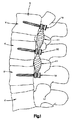
図1を参照すると、個々の椎骨Vを、後部から安定化させている。特に、骨固定要素10は、後部方向から、3つの椎骨Vに固定されている。骨固定要素10の頭部は、それぞれ通路を有し、これらは一般的にロッド受入れ通路と称されて、ダイナミックケーブルシステム11の部分を、それぞれ収容し及び/又は受け入れる。ダイナミックケーブルシステム11は好ましくは、骨固定要素10に対して固定されることができ、そのためには、一般的に当業者が理解するように、例えば、封止キャップ又は止めねじによって、通路内にダイナミックケーブルシステム11を固定する。このようにして、患者の脊椎Sは安定する。
Referring to FIG. 1, individual vertebrae V are stabilized from the back. In particular, the
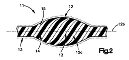
図1乃至図4を参照すると、ダイナミックケーブルシステム11は、長手ケーブル12を具備し、これには内部キャビティ12aが組み込まれている。緩衝材料13は好ましくは、内部キャビティ12aの内部に配置され、ケーブル12に緩衝特性を提供している。ケーブル12は好ましくは、個々のストランド及び/又はファイバー14(本願ではまとめてファイバーと称する。)から製造され、それらは一緒に編まれる。緩衝材料13は、ケーブル12の中に挿入され、緩衝材料は、少なくとも部分的に、ケーブル12によって取り囲まれ、又は少なくとも部分的に包被される。これを達成するには、例えば、ケーブル12を捩って、ケーブル12における個々のファイバー14を分離して、個々のファイバー14の間に隙間15を形成させる。緩衝材料13は好ましくは、隙間15を介して内部キャビティ12aの中に挿入される。変形例としては、ケーブル12は、個々のファイバー14の間に自然に生じる隙間15を具備し、ファイバー14を捩って引き離す必要性を解消する。変形例としては、緩衝材料13は、当業者に知られている任意の手段によって、ケーブル12に形成された内部キャビティ12aの中に挿入される。例えば、緩衝材料13は、任意の数の形状、例えば、円筒形又は卵形に事前成形され、次に、ケーブル12の内部キャビティ12aの中に挿入される。
With reference to FIGS. 1-4, the
緩衝材料13は好ましくは、ケーブル12の内部キャビティ12aの中に射出成形され、より好ましくは、ケーブル12の個々のファイバーの間に形成された中間的な隙間15に射出成形される。このように、緩衝材料13が硬化して硬くなると、緩衝材料13は隙間15を充填し、次に、緩衝材料13をケーブル12から係脱及び/又は分離して保つ助けになる。
The cushioning
代わりに及び/又は加えて、緩衝材料13は、ケーブル12のまわりに射出成形され、緩衝材料13は、少なくとも部分的に、ケーブル12を取り囲む。このように、緩衝材料13は、ケーブル12の内部キャビティ12aによって形成された空間と、個々のファイバー14の中間の隙間15によって形成された空間とを占有し、少なくとも部分的に、ケーブル12を取り囲む。異なる弾性品質をもった異なる緩衝材料を使用して、緩衝材料13が構成される。例えば、緩衝材料13は、ケーブル12の内部キャビティ12aの中に挿入された第1の材料と、ケーブル12を取り囲む第2の材料とから構成される。好ましい実施形態においては、緩衝材料13は、同一の材料から構成される。
Alternatively and / or additionally, the cushioning
現場において、取り付けられた椎骨Vが動くと、骨固定要素10を介して、椎骨Vからダイナミックケーブルシステム11に動き及び関連する荷重が伝達される。このように、ダイナミックケーブルシステム11は、取り付けられた椎骨Vが互いに動くことを許容する。可撓性ケーブル12と緩衝材料13との組合せは、いくらかの又はすべての運動(例えば、並進、関節、回転(例えば、捩り)など)と、関連する荷重及び/又は応力とを吸収する。
As the attached vertebra V moves in the field, movement and associated loads are transmitted from the vertebra V to the
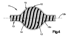
図3を参照すると、ダイナミックケーブルシステム11に張力が加わると、ケーブル12は伸張し、ケーブル12の中央部分は細くなる。張力/屈曲応力は、少なくとも部分的に、ケーブル12によって吸収され、横方向の圧縮応力は、少なくとも部分的に、緩衝材料13によって伝達され吸収される。また、ケーブル12を使用すると、緩衝材料13の軸線及び並進移動を制限することによって、緩衝材料13の歪みは制限される。
Referring to FIG. 3, when tension is applied to the
ケーブル12に許される軸線運動の量は、例えば、ケーブル12の個々のファイバーがケーブル12の長手軸線12bを中心として巻き付けられる角度によって拘束される。例えば、ファイバー14を平らな(すなわち、長手軸線12bに対してより平行な)角度に巻き付けると、ファイバー14を急峻な(すなわち、長手軸線12bに対してより垂直な)角度に巻き付ける場合と比べて、より少ない軸線運動が許容される。好ましくは、ケーブル12におけるファイバー14は、約15゜から約75゜の範囲の角度に巻き付けられる。より好ましくは、ファイバー14は、約25゜から約65゜の範囲の角度に巻き付けられる。より好ましくは、ファイバー14は、約45゜の角度に巻き付けられる。
The amount of axial movement allowed for the
ダイナミックケーブルシステム11に許される回転運動の量は、例えば、ケーブル12を、反対方向に編まれた2以上の組のファイバー14から製造することで、制約される。1つの実施形態においては、例えば、2組のファイバー14がかみ合う。さらに及び/又は代わりに、1組のファイバー14が、他の組のファイバー14のまわりに巻き付けられる。それぞれの組のファイバー14は、ファイバー14が編まれている方向において回転運動を制限し、これは例えば、タイヤ又は炭素強化ファイバーマトリックスに使用される編組ファイバーと同様である。加えて、2以上の同軸的に編まれたファイバー又はコードを使用して、堅さの漸増(長手軸線12bからの距離f(x)の関数として)を達成できる。使用されるファイバー14は、捩られ、組まれ、織られ、又は編まれる。
The amount of rotational motion allowed for the
図4を参照すると、ダイナミックケーブルシステム11を圧縮下の荷重に置くと、ケーブル12は、圧縮され及び/又はコイル状に巻かれ、これはケーブル12を中央部分において幅広にする。その結果、軸線圧縮応力は、少なくとも部分的に、緩衝材料13によって伝達及び吸収される。
Referring to FIG. 4, when the
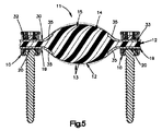
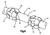
図5乃至図7を参照すると、ダイナミックケーブルシステム11は、1又は複数のクランプスリーブ19に関連して使用される。クランプスリーブ19は、第1の端部30と、第2の端部31と、中間クランプ領域32と、第1の端部30から第2の端部31へと延在するボア33とを具備している。中間クランプ領域32は好ましくは、骨固定要素10に形成された通路の中に、受け入れられ、次に、固定される。変形例としては、クランプスリーブ19は、第1の端部30と、クランプ領域32と、ボア33とだけを具備してもよい。この構成は、2つの隣接する椎骨Vを橋渡しするために、又は3以上の椎骨Vを橋渡しするとき、端部の椎骨Vに使用するために、特に有用である。
With reference to FIGS. 5-7, the
クランプスリーブ19は好ましくは、ダイナミックケーブルシステム11を、より好ましくはケーブル12を、少なくとも部分的に取り囲む。すなわち、クランプスリーブ19に形成されたボア33は好ましくは、ケーブル12を内部に受け入れる。ケーブル12は好ましくは、クランプスリーブ19のボア33の内部に、摺動可能に配置される。クランプスリーブ19は好ましくは、ケーブル12が骨固定要素10の通路の内部に受け入れられる位置(例えば、クランプ部位20)においてケーブル12を取り囲む。クランプスリーブ19は、ダイナミックケーブルシステム11を骨固定要素10に取り付けるのを容易にし、骨固定要素は椎骨Vに固定される。クランプスリーブ19は好ましくは、ケーブル12を取り囲み、ケーブル12をクランプ部位20における剪断から保護する。従って、クランプスリーブ19は、ケーブル12を、ケーブル12が圧縮及び張力を受けるときに骨固定要素10によって生じる、塑性変形及びV字応力から保護する。
The
クランプスリーブ19における第1の端部30及び第2の端部31は、そこから複数のタブ35を延在させ、タブは複数の凹部36によって分離されている。タブ35と凹部36とは好ましくは、例えば、並進中及び/又は屈曲/伸張中の場合のように、緩衝要素13が変形の増加を示したとき、剛性の漸減を可能にする。一般的に認識されるように、クランプスリーブ19は好ましくは、クランプ部位20における変形を許容し、一方、依然として、緩衝材料13をV字応力から保護する。さらに、隣接するクランプスリーブ19に形成されたタブ35と凹部36とは、互いに回転方向にオフセットしており、1つのスリーブ19に形成されたタブ35は、隣接するスリーブ19に形成された凹部36と整列される。図示の通り、クランプスリーブ19は、4つのタブ35を具備し、クランプスリーブ19の第1の端部30及び第2の端部31のまわりに均等に配置されるが、より多数の又はより少数のタブ35を使用することも想定される。
The
緩衝材料13は好ましくは、ケーブル12がクランプスリーブ19の中に挿入された後に、ケーブル12の中に射出成形される。このように、あるとしてもわずかな、緩衝材料13がケーブル12のクランプ部分32(例えば、クランプスリーブ19のボア33の中に挿入された、ケーブル12の部分)に配置される。変形例としては、ケーブル12の全体に、緩衝材料13を配置してもよい。前述したように、ケーブル12は、クランプスリーブ19のボア33の内部に、自由に受け入れられ及び/又は摺動可能に配置される。ケーブル12は、代替的には、クランプスリーブ19に固定される。好ましくは、ケーブル12の内部キャビティ12aの中に緩衝材料13が射出成形されるまで、ケーブル12は、クランプスリーブ19のボア33の内部に、自由に受け入れられ及び/又は摺動可能に配置される。射出成形の後には、ケーブル12の位置は好ましくは、クランプスリーブ19に対して固定される。ケーブル12は、当業者に公知である任意の手段によって、クランプスリーブ19に固定され、それらには、限定はしないが、接着、クランプスリーブ19のかしめ、ねじ、ボルト、クランプ、ピン、組紐などが含まれる。
The
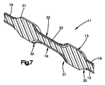
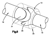
図7及び図8を参照すると、ダイナミックケーブルシステム11は、ケーブル12のまわりにモールド成形又は射出成形された、追加的な緩衝材料13を組み込まれる。追加的な緩衝材料13は好ましくは、隣接するクランプスリーブ19における第1の端部30及び第2の端部31を、及び好ましくは、ケーブル12の露出部分を、少なくとも部分的に、取り囲み及び/又は包被する。追加的な緩衝材料13は、いくらかの剪断力を吸収すると共に、脊椎Sの拡張又は圧縮による衝撃のいくらかを吸収する。加えて、ケーブル12の露出部分のまわりに追加的な緩衝材料13を組み込むことは、ケーブル12の全体が摩耗及び破片の蓄積に対して保護することを確実にする助けになる。すなわち、ケーブル12のまわりに配置された、オプションである追加的な緩衝材料13は、ダイナミックケーブルシステム11から摩耗破片が逃げることを防ぐ保護層であると見ることができる。
Referring to FIGS. 7 and 8, the
使用に際しては、ダイナミックケーブルシステム11の長さは、固定される椎骨Vのサイズ及び数に依存する。例えば、仮に、患者の全体の脊椎を固定し及び/又は備えるならば、ケーブル12の長さは、1メートル(1m)までの長さになる。当業者に一般的に理解されるように、ケーブル12の直径は、予想される荷重を吸収するサイズに定められる。従って、腰部領域に使用されるケーブル12のサイズは、代表的に、胸部又は頚部の領域に使用されるケーブル12に比べて、大きな直径を有する。例えば、ケーブル12の直径は、脊椎の腰部領域に使用するためには、1ミリメートル(1mm)から20ミリメートル(20mm)の範囲であり、又は脊椎の頚部領域に使用するためには、1ミリメートル(1mm)から15ミリメートル(15mm)の範囲である。変形例としては、ケーブル12は、その全長にわたって、均一な直径を有する。ケーブル12における薄い又はクランプ部分は、ケーブル12をしっかりと捩り又は編むことで製造され、クランプ領域のための薄い部分が達成される。
In use, the length of the
当業者によって認識されるように、本願で開示した任意の又はすべての構成要素、例えば、骨固定要素10、ケーブル12、クランプスリーブ19などは、セット又はキットとして提供され、外科医は、様々な構成要素の組合せを選択して、固定手順を実行し、及び、患者の特定のニーズ/解剖学のために特に構成された固定システムを創り出す。それぞれの構成要素の1又は複数のものは、キット又はセットにて提供されることに留意されたい。いくつかのキット又はセットにおいて、同一の装置が、異なる形状及び/又はサイズにおいて提供される(例えば、異なるサイズの複数の骨固定要素10、ケーブル12、及び/又はクランプスリーブ19)。
As will be appreciated by those skilled in the art, any or all of the components disclosed herein, such as
当業者に認識されるように、広い発明的概念から逸脱せずに、前述した実施形態に対しては、変更を施すことができる。従って、本発明は、開示された特定の実施形態に限定されることがなく、特許請求の範囲によって定められた本発明の精神及び範囲の中での改変を包含する意図であることが理解される。 As will be appreciated by those skilled in the art, changes may be made to the embodiments described above without departing from the broad inventive concept. Accordingly, it is to be understood that the invention is not limited to the specific embodiments disclosed, but is intended to encompass modifications within the spirit and scope of the invention as defined by the appended claims. The
Claims (15)
内部キャビティを有する長手ケーブルであって、長手ケーブルは、通路の内部にて位置決め可能であるような、上記長手ケーブルと、
内部キャビティの中に射出成形された少なくとも1つの緩衝材料であって、長手ケーブルは、網組ケーブル、織布ケーブル、組紐ケーブル、編物ケーブル、捩りケーブル、及び、管からなるグループから選択されている、上記緩衝材料と、
を備えていることを特徴とするダイナミックケーブルシステム。 A dynamic cable system for bridging two or more adjacent vertebrae, each vertebra having at least one bone anchoring element attached thereto, each bone anchoring element having a passage formed therein The dynamic cable system comprises
A longitudinal cable having an internal cavity, the longitudinal cable being positionable within the passageway; and
At least one cushioning material injection molded into the internal cavity, wherein the longitudinal cable is selected from the group consisting of braided cable, woven cable, braided cable, knitted cable, twisted cable, and tube , The buffer material,
A dynamic cable system characterized by comprising:
少なくとも1つのクランプスリーブであって、ケーブルの少なくとも一部分を受け入れるボアを具備し、少なくとも1つのクランプスリーブは、通路の1つの内部に受け入れられる、上記クランプスリーブ、
を備えていることを特徴とする請求項1に記載のダイナミックケーブルシステム。 Dynamic cable system
At least one clamp sleeve comprising a bore for receiving at least a portion of the cable, wherein the at least one clamp sleeve is received within one of the passages;
The dynamic cable system according to claim 1, further comprising:
第1の椎骨に取り付けられた第1の骨固定要素であって、第1の通路を内部に形成されて有している、上記第1の骨固定要素と、
第2の椎骨に取り付けられた第2の骨固定要素であって、第2の通路を内部に形成されて有している、上記第2の骨固定要素と、
第1のクランプスリーブであって、第1のボアを具備し、第1のクランプスリーブは、少なくとも部分的に、第1の通路の内部に配置されている、上記第1のクランプスリーブと、
第2のクランプスリーブであって、第2のボアを具備し、第2のクランプスリーブは、少なくとも部分的に、第2の通路の内部に配置されている、上記第2のクランプスリーブと、
長手ケーブルであって、第1の端部と、第2の端部と、内部キャビティとを有し、第1の端部は、第1のボアの内部に受け入れられ、第2の端部は、第2のボアの内部に受け入れられる、上記長手ケーブルと、
少なくとも内部キャビティの内部に配置された緩衝材料であって、ケーブルが、網組ケーブル、織布ケーブル、組紐ケーブル、編物ケーブル、捩りケーブル、及び、管のうちの1つから選択されている、上記緩衝材料と、
を備えていることを特徴とするダイナミック固定システム。 A dynamic fixation system for bridging between a first vertebra and a second vertebra, wherein the first vertebra is positioned adjacent to the second vertebra, the dynamic fixation system comprising:
A first bone anchoring element attached to the first vertebra, the first bone anchoring element having a first passage formed therein;
A second bone anchoring element attached to the second vertebra, the second bone anchoring element having a second passage formed therein;
A first clamping sleeve comprising a first bore, wherein the first clamping sleeve is at least partially disposed within the first passage;
A second clamp sleeve, comprising a second bore, wherein the second clamp sleeve is at least partially disposed within the second passage;
A longitudinal cable having a first end, a second end, and an internal cavity, the first end being received within the first bore, the second end being The longitudinal cable received within the second bore;
A cushioning material disposed at least within an internal cavity, wherein the cable is selected from one of a braided cable, a woven cable, a braided cable, a knitted cable, a twisted cable, and a tube; Buffer material,
A dynamic fixing system characterized by comprising:
長手ケーブルのまわりに射出成形された少なくとも1つの緩衝材料であって、長手ケーブルにおける少なくとも一部分が緩衝材料によって包被されている、上記緩衝材料、
を備えていることを特徴とする請求項11に記載のダイナミック固定システム。 A dynamic locking system,
At least one cushioning material injection molded around the longitudinal cable, wherein at least a portion of the longitudinal cable is encapsulated by the cushioning material;
The dynamic fixation system according to claim 11, comprising:
Applications Claiming Priority (2)
| Application Number | Priority Date | Filing Date | Title |
|---|---|---|---|
| US95444307P | 2007-08-07 | 2007-08-07 | |
| PCT/US2008/072481 WO2009021116A2 (en) | 2007-08-07 | 2008-08-07 | Dynamic cable system |
Publications (1)
| Publication Number | Publication Date |
|---|---|
| JP2010535593A true JP2010535593A (en) | 2010-11-25 |
Family
ID=40342040
Family Applications (1)
| Application Number | Title | Priority Date | Filing Date |
|---|---|---|---|
| JP2010520308A Pending JP2010535593A (en) | 2007-08-07 | 2008-08-07 | Dynamic cable system |
Country Status (9)
| Country | Link |
|---|---|
| US (1) | US20110230914A1 (en) |
| EP (1) | EP2178451A2 (en) |
| JP (1) | JP2010535593A (en) |
| KR (1) | KR20100051617A (en) |
| CN (1) | CN101801293A (en) |
| BR (1) | BRPI0814831A2 (en) |
| CA (1) | CA2693540A1 (en) |
| CO (1) | CO6260037A2 (en) |
| WO (1) | WO2009021116A2 (en) |
Families Citing this family (28)
| Publication number | Priority date | Publication date | Assignee | Title |
|---|---|---|---|---|
| WO2006044727A2 (en) | 2004-10-15 | 2006-04-27 | Baxano, Inc. | Devices and methods for tissue removal |
| US8048080B2 (en) | 2004-10-15 | 2011-11-01 | Baxano, Inc. | Flexible tissue rasp |
| US20100331883A1 (en) | 2004-10-15 | 2010-12-30 | Schmitz Gregory P | Access and tissue modification systems and methods |
| US20110190772A1 (en) | 2004-10-15 | 2011-08-04 | Vahid Saadat | Powered tissue modification devices and methods |
| US9247952B2 (en) | 2004-10-15 | 2016-02-02 | Amendia, Inc. | Devices and methods for tissue access |
| US9101386B2 (en) | 2004-10-15 | 2015-08-11 | Amendia, Inc. | Devices and methods for treating tissue |
| US8257356B2 (en) | 2004-10-15 | 2012-09-04 | Baxano, Inc. | Guidewire exchange systems to treat spinal stenosis |
| US8613745B2 (en) | 2004-10-15 | 2013-12-24 | Baxano Surgical, Inc. | Methods, systems and devices for carpal tunnel release |
| US8221397B2 (en) | 2004-10-15 | 2012-07-17 | Baxano, Inc. | Devices and methods for tissue modification |
| US8062298B2 (en) | 2005-10-15 | 2011-11-22 | Baxano, Inc. | Flexible tissue removal devices and methods |
| US20080086034A1 (en) | 2006-08-29 | 2008-04-10 | Baxano, Inc. | Tissue Access Guidewire System and Method |
| US8366712B2 (en) | 2005-10-15 | 2013-02-05 | Baxano, Inc. | Multiple pathways for spinal nerve root decompression from a single access point |
| US8092456B2 (en) | 2005-10-15 | 2012-01-10 | Baxano, Inc. | Multiple pathways for spinal nerve root decompression from a single access point |
| EP2194861A1 (en) | 2007-09-06 | 2010-06-16 | Baxano, Inc. | Method, system and apparatus for neural localization |
| US8192436B2 (en) | 2007-12-07 | 2012-06-05 | Baxano, Inc. | Tissue modification devices |
| US8398641B2 (en) | 2008-07-01 | 2013-03-19 | Baxano, Inc. | Tissue modification devices and methods |
| WO2010009093A2 (en) | 2008-07-14 | 2010-01-21 | Baxano, Inc | Tissue modification devices |
| US9314253B2 (en) | 2008-07-01 | 2016-04-19 | Amendia, Inc. | Tissue modification devices and methods |
| CA2749673A1 (en) | 2009-03-13 | 2010-09-16 | Baxano, Inc. | Flexible neural localization devices and methods |
| US8394102B2 (en) | 2009-06-25 | 2013-03-12 | Baxano, Inc. | Surgical tools for treatment of spinal stenosis |
| US9770359B2 (en) | 2010-03-19 | 2017-09-26 | Coloplast A/S | Ostomy base plate with mouldable inner adhesive |
| DK2608728T3 (en) | 2010-08-26 | 2018-01-22 | Spinesave Ag | Vertebral column implant kit for dynamic stabilization of the vertebral column |
| US10004603B2 (en) | 2012-08-23 | 2018-06-26 | DePuy Synthes Products, Inc. | Bone implant |
| CN104736080B (en) * | 2012-08-23 | 2017-08-04 | 新特斯有限责任公司 | Bone fixation system |
| US9452005B2 (en) | 2012-08-23 | 2016-09-27 | DePuy Synthes Products, Inc. | Bone fixation system |
| GB201220042D0 (en) | 2012-11-07 | 2012-12-19 | Murray David W | Adjusting spinal curvature |
| CN104000645B (en) * | 2014-06-10 | 2017-01-18 | 张衣北 | Dynamic fixing system of posterior spinal |
| EP3897414A4 (en) | 2018-12-21 | 2022-09-28 | Paradigm Spine, LLC. | Modular spine stabilization system and associated instruments |
Citations (7)
| Publication number | Priority date | Publication date | Assignee | Title |
|---|---|---|---|---|
| US20040049189A1 (en) * | 2000-07-25 | 2004-03-11 | Regis Le Couedic | Flexible linking piece for stabilising the spine |
| JP2005007177A (en) * | 2003-06-16 | 2005-01-13 | Ulrich Gmbh & Co Kg | Implant for correction and stabilization of spinal column |
| US20050171538A1 (en) * | 2002-02-11 | 2005-08-04 | Frederic Sgier | Vertebral arthrodesis device |
| WO2005086650A2 (en) * | 2004-02-27 | 2005-09-22 | Custom Spine, Inc. | Medialised rod pedicle screw assembly |
| JP2005253971A (en) * | 2004-03-09 | 2005-09-22 | Biedermann Motech Gmbh | Bar-like element and stabilizing device used in operation for spinal cord and external injury |
| WO2005122925A1 (en) * | 2004-06-09 | 2005-12-29 | Sdgi Holdings, Inc. | Systems and methods for flexible spinal stabilization |
| WO2006063107A2 (en) * | 2003-09-24 | 2006-06-15 | N Spine, Inc. | Spinal stabilization device |
Family Cites Families (96)
| Publication number | Priority date | Publication date | Assignee | Title |
|---|---|---|---|---|
| GB1551706A (en) * | 1975-04-28 | 1979-08-30 | Downs Surgical Ltd | Surgical implant |
| US4369769A (en) * | 1980-06-13 | 1983-01-25 | Edwards Charles C | Spinal fixation device and method |
| US4448191A (en) * | 1981-07-07 | 1984-05-15 | Rodnyansky Lazar I | Implantable correctant of a spinal curvature and a method for treatment of a spinal curvature |
| US4743260A (en) * | 1985-06-10 | 1988-05-10 | Burton Charles V | Method for a flexible stabilization system for a vertebral column |
| SE466732B (en) * | 1987-10-29 | 1992-03-30 | Atos Medical Ab | LED PROTES, INCLUDING A LED BODY BETWEEN ONE COUPLE OF TAPS FOR INSTALLATION |
| DE8807485U1 (en) * | 1988-06-06 | 1989-08-10 | Mecron Medizinische Produkte Gmbh, 1000 Berlin, De | |
| USRE36221E (en) * | 1989-02-03 | 1999-06-01 | Breard; Francis Henri | Flexible inter-vertebral stabilizer as well as process and apparatus for determining or verifying its tension before installation on the spinal column |
| CH678803A5 (en) * | 1989-07-12 | 1991-11-15 | Sulzer Ag | |
| US4932975A (en) * | 1989-10-16 | 1990-06-12 | Vanderbilt University | Vertebral prosthesis |
| FR2666981B1 (en) * | 1990-09-21 | 1993-06-25 | Commarmond Jacques | SYNTHETIC LIGAMENT VERTEBRAL. |
| FR2676911B1 (en) * | 1991-05-30 | 1998-03-06 | Psi Ste Civile Particuliere | INTERVERTEBRAL STABILIZATION DEVICE WITH SHOCK ABSORBERS. |
| GB9217578D0 (en) * | 1992-08-19 | 1992-09-30 | Surgicarft Ltd | Surgical implants,etc |
| US5814046A (en) * | 1992-11-13 | 1998-09-29 | Sofamor S.N.C. | Pedicular screw and posterior spinal instrumentation |
| DE4243951C2 (en) * | 1992-12-23 | 1997-07-03 | Plus Endoprothetik Ag | Device for stiffening a spinal column section consisting of at least two vertebrae |
| US5413576A (en) * | 1993-02-10 | 1995-05-09 | Rivard; Charles-Hilaire | Apparatus for treating spinal disorder |
| FR2701650B1 (en) * | 1993-02-17 | 1995-05-24 | Psi | Double shock absorber for intervertebral stabilization. |
| US5415661A (en) * | 1993-03-24 | 1995-05-16 | University Of Miami | Implantable spinal assist device |
| US5423816A (en) * | 1993-07-29 | 1995-06-13 | Lin; Chih I. | Intervertebral locking device |
| FR2709247B1 (en) * | 1993-08-27 | 1995-09-29 | Martin Jean Raymond | Device for anchoring spinal instrumentation on a vertebra. |
| FR2709246B1 (en) * | 1993-08-27 | 1995-09-29 | Martin Jean Raymond | Dynamic implanted spinal orthosis. |
| ES2081766B1 (en) * | 1994-05-13 | 1996-10-01 | Bilbao Ortiz De Zarate Jose Ra | POSTERIOR CERVICAL VERTEBRAL FIXATION SYSTEM. |
| US5488761A (en) * | 1994-07-28 | 1996-02-06 | Leone; Ronald P. | Flexible shaft and method for manufacturing same |
| FR2724553B1 (en) * | 1994-09-15 | 1996-12-20 | Tornier Sa | EXTERNAL OR INTERNAL FIXER FOR THE REPAIR OF FRACTURES OR ARTHROPLASTIES OF THE SKELETON |
| WO1997003611A1 (en) * | 1995-07-18 | 1997-02-06 | Edwards, Garland, U. | Flexible shaft |
| US5658286A (en) * | 1996-02-05 | 1997-08-19 | Sava; Garard A. | Fabrication of implantable bone fixation elements |
| US5713900A (en) * | 1996-05-31 | 1998-02-03 | Acromed Corporation | Apparatus for retaining bone portions in a desired spatial relationship |
| FR2755844B1 (en) * | 1996-11-15 | 1999-01-29 | Stryker France Sa | OSTEOSYNTHESIS SYSTEM WITH ELASTIC DEFORMATION FOR SPINE |
| IL128261A0 (en) * | 1999-01-27 | 1999-11-30 | Disc O Tech Medical Tech Ltd | Expandable element |
| DE29711559U1 (en) * | 1997-07-02 | 1997-08-21 | Howmedica Gmbh | Elongated element for the transmission of forces |
| JP2001511388A (en) * | 1997-07-31 | 2001-08-14 | プルス エンドプロシェティク アーゲー | Device for reinforcing and / or correcting the spine, etc. |
| US5964769A (en) * | 1997-08-26 | 1999-10-12 | Spinal Concepts, Inc. | Surgical cable system and method |
| FR2771280B1 (en) * | 1997-11-26 | 2001-01-26 | Albert P Alby | RESILIENT VERTEBRAL CONNECTION DEVICE |
| FR2774581B1 (en) * | 1998-02-10 | 2000-08-11 | Dimso Sa | INTEREPINOUS STABILIZER TO BE ATTACHED TO SPINOUS APOPHYSIS OF TWO VERTEBRES |
| JP2003523784A (en) * | 1999-04-05 | 2003-08-12 | サージカル ダイナミックス インコーポレイテッド | Artificial spinal ligament |
| US6893462B2 (en) * | 2000-01-11 | 2005-05-17 | Regeneration Technologies, Inc. | Soft and calcified tissue implants |
| US20020133155A1 (en) * | 2000-02-25 | 2002-09-19 | Ferree Bret A. | Cross-coupled vertebral stabilizers incorporating spinal motion restriction |
| FR2805451B1 (en) * | 2000-02-29 | 2002-04-19 | Arnaud Andre Soubeiran | IMPROVED DEVICE FOR MOVING TWO BODIES IN RELATION TO ONE ANOTHER, PARTICULARLY FOR REALIZING IMPLANTABLE SYSTEMS IN THE HUMAN BODY |
| US6402750B1 (en) * | 2000-04-04 | 2002-06-11 | Spinlabs, Llc | Devices and methods for the treatment of spinal disorders |
| US6749614B2 (en) * | 2000-06-23 | 2004-06-15 | Vertelink Corporation | Formable orthopedic fixation system with cross linking |
| US6899713B2 (en) * | 2000-06-23 | 2005-05-31 | Vertelink Corporation | Formable orthopedic fixation system |
| US6875212B2 (en) * | 2000-06-23 | 2005-04-05 | Vertelink Corporation | Curable media for implantable medical device |
| US6554831B1 (en) * | 2000-09-01 | 2003-04-29 | Hopital Sainte-Justine | Mobile dynamic system for treating spinal disorder |
| DE50106374D1 (en) * | 2000-09-18 | 2005-07-07 | Zimmer Gmbh Winterthur | Pedicle screw for intervertebral support elements |
| US6551320B2 (en) * | 2000-11-08 | 2003-04-22 | The Cleveland Clinic Foundation | Method and apparatus for correcting spinal deformity |
| AU2002248223A1 (en) * | 2000-12-29 | 2002-07-24 | James Thomas | Vertebral alignment system |
| FR2819711B1 (en) * | 2001-01-23 | 2003-08-01 | Stryker Spine Sa | POSITION ADJUSTMENT SYSTEM FOR A SPINAL SURGERY INSTRUMENT |
| US7229441B2 (en) * | 2001-02-28 | 2007-06-12 | Warsaw Orthopedic, Inc. | Flexible systems for spinal stabilization and fixation |
| US6706044B2 (en) * | 2001-04-19 | 2004-03-16 | Spineology, Inc. | Stacked intermedular rods for spinal fixation |
| US7862587B2 (en) * | 2004-02-27 | 2011-01-04 | Jackson Roger P | Dynamic stabilization assemblies, tool set and method |
| FR2827498B1 (en) * | 2001-07-18 | 2004-05-14 | Frederic Fortin | FLEXIBLE VERTEBRAL CONNECTION DEVICE CONSISTING OF PALLIANT ELEMENTS OF THE RACHIS |
| JP2004537354A (en) * | 2001-07-20 | 2004-12-16 | スパイナル・コンセプツ・インコーポレーテッド | Spinal stabilization system and method |
| JP4755781B2 (en) * | 2001-08-01 | 2011-08-24 | 昭和医科工業株式会社 | Jointing member for osteosynthesis |
| US6884241B2 (en) * | 2001-09-04 | 2005-04-26 | Orthotec, Llc | Spinal assembly plate |
| FR2831420B1 (en) * | 2001-10-30 | 2004-07-16 | Vitatech | APPARATUS FOR HOLDING THE SPIN WITH JOINTING ASSEMBLY |
| US6783527B2 (en) * | 2001-10-30 | 2004-08-31 | Sdgi Holdings, Inc. | Flexible spinal stabilization system and method |
| US7285121B2 (en) * | 2001-11-05 | 2007-10-23 | Warsaw Orthopedic, Inc. | Devices and methods for the correction and treatment of spinal deformities |
| US7682375B2 (en) * | 2002-05-08 | 2010-03-23 | Stephen Ritland | Dynamic fixation device and method of use |
| DE10236691B4 (en) * | 2002-08-09 | 2005-12-01 | Biedermann Motech Gmbh | Dynamic stabilization device for bones, in particular for vertebrae |
| FR2843538B1 (en) * | 2002-08-13 | 2005-08-12 | Frederic Fortin | DEVICE FOR DISTRACTING AND DAMPING ADJUSTABLE TO THE GROWTH OF THE RACHIS |
| AU2003265597A1 (en) * | 2002-08-23 | 2004-03-11 | Paul C. Mcafee | Metal-backed uhmpe rod sleeve system preserving spinal motion |
| FR2844180B1 (en) * | 2002-09-11 | 2005-08-05 | Spinevision | CONNECTING ELEMENT FOR THE DYNAMIC STABILIZATION OF A SPINAL FIXING SYSTEM AND SPINAL FASTENING SYSTEM COMPRISING SUCH A MEMBER |
| FR2845587B1 (en) * | 2002-10-14 | 2005-01-21 | Scient X | DYNAMIC DEVICE FOR INTERVERTEBRAL CONNECTION WITH MULTIDIRECTIONALLY CONTROLLED DEBATMENT |
| US20040147928A1 (en) * | 2002-10-30 | 2004-07-29 | Landry Michael E. | Spinal stabilization system using flexible members |
| US7473267B2 (en) * | 2003-04-25 | 2009-01-06 | Warsaw Orthopedic, Inc. | System and method for minimally invasive posterior fixation |
| US8652175B2 (en) * | 2003-05-02 | 2014-02-18 | Rachiotek, Llc | Surgical implant devices and systems including a sheath member |
| US20050182401A1 (en) * | 2003-05-02 | 2005-08-18 | Timm Jens P. | Systems and methods for spine stabilization including a dynamic junction |
| US20050182400A1 (en) * | 2003-05-02 | 2005-08-18 | Jeffrey White | Spine stabilization systems, devices and methods |
| US20050171543A1 (en) * | 2003-05-02 | 2005-08-04 | Timm Jens P. | Spine stabilization systems and associated devices, assemblies and methods |
| US6986771B2 (en) * | 2003-05-23 | 2006-01-17 | Globus Medical, Inc. | Spine stabilization system |
| US7766915B2 (en) * | 2004-02-27 | 2010-08-03 | Jackson Roger P | Dynamic fixation assemblies with inner core and outer coil-like member |
| US7794476B2 (en) * | 2003-08-08 | 2010-09-14 | Warsaw Orthopedic, Inc. | Implants formed of shape memory polymeric material for spinal fixation |
| US20050065516A1 (en) * | 2003-09-24 | 2005-03-24 | Tae-Ahn Jahng | Method and apparatus for flexible fixation of a spine |
| US20050090822A1 (en) * | 2003-10-24 | 2005-04-28 | Dipoto Gene | Methods and apparatus for stabilizing the spine through an access device |
| WO2005037150A1 (en) * | 2003-10-16 | 2005-04-28 | Osteotech, Inc. | System and method for flexible correction of bony motion segment |
| DE10348329B3 (en) * | 2003-10-17 | 2005-02-17 | Biedermann Motech Gmbh | Rod-shaped element used in spinal column and accident surgery for connecting two bone-anchoring elements comprises a rigid section and an elastic section that are made in one piece |
| EP1673048B1 (en) * | 2003-10-17 | 2013-06-19 | Biedermann Technologies GmbH & Co. KG | Flexible implant |
| US8632570B2 (en) * | 2003-11-07 | 2014-01-21 | Biedermann Technologies Gmbh & Co. Kg | Stabilization device for bones comprising a spring element and manufacturing method for said spring element |
| US7862586B2 (en) * | 2003-11-25 | 2011-01-04 | Life Spine, Inc. | Spinal stabilization systems |
| US7597694B2 (en) * | 2004-01-30 | 2009-10-06 | Warsaw Orthopedic, Inc. | Instruments and methods for minimally invasive spinal stabilization |
| US7297146B2 (en) * | 2004-01-30 | 2007-11-20 | Warsaw Orthopedic, Inc. | Orthopedic distraction implants and techniques |
| US7815664B2 (en) * | 2005-01-04 | 2010-10-19 | Warsaw Orthopedic, Inc. | Systems and methods for spinal stabilization with flexible elements |
| FR2867057B1 (en) * | 2004-03-02 | 2007-06-01 | Spinevision | DYNAMIC BONDING ELEMENT FOR A SPINAL FIXING SYSTEM AND FIXING SYSTEM COMPRISING SUCH A CONNECTING MEMBER |
| US7686833B1 (en) * | 2004-04-02 | 2010-03-30 | Muhanna Nabil L | Ball jointed pedicle screw and rod system |
| US7833256B2 (en) * | 2004-04-16 | 2010-11-16 | Biedermann Motech Gmbh | Elastic element for the use in a stabilization device for bones and vertebrae and method for the manufacture of such elastic element |
| EP1740111B1 (en) * | 2004-04-28 | 2009-08-05 | Synthes GmbH | Device for dynamic bone stabilization |
| GB2414674B (en) * | 2004-06-04 | 2009-08-12 | John Burke | Apparatus for the correction of skeletal deformities |
| ZA200700451B (en) * | 2004-06-23 | 2008-10-29 | Applied Spine Technologies Inc | Systems and methods for spine stabilization |
| US7854752B2 (en) * | 2004-08-09 | 2010-12-21 | Theken Spine, Llc | System and method for dynamic skeletal stabilization |
| US8162985B2 (en) * | 2004-10-20 | 2012-04-24 | The Board Of Trustees Of The Leland Stanford Junior University | Systems and methods for posterior dynamic stabilization of the spine |
| US8267967B2 (en) * | 2004-12-15 | 2012-09-18 | Stryker Spine | Methods and apparatus for modular and variable spinal fixation |
| US7604654B2 (en) * | 2005-02-22 | 2009-10-20 | Stryker Spine | Apparatus and method for dynamic vertebral stabilization |
| US20060264937A1 (en) * | 2005-05-04 | 2006-11-23 | White Patrick M | Mobile spine stabilization device |
| US7776075B2 (en) * | 2006-01-31 | 2010-08-17 | Warsaw Orthopedic, Inc. | Expandable spinal rods and methods of use |
| US8449576B2 (en) * | 2006-06-28 | 2013-05-28 | DePuy Synthes Products, LLC | Dynamic fixation system |
| US7967847B2 (en) * | 2006-07-24 | 2011-06-28 | Warsaw Orthopedic, Inc. | Spinal stabilization and reconstruction with fusion rods |
| US8029544B2 (en) * | 2007-01-02 | 2011-10-04 | Zimmer Spine, Inc. | Spine stiffening device |
-
2008
- 2008-08-07 EP EP08827149A patent/EP2178451A2/en not_active Withdrawn
- 2008-08-07 JP JP2010520308A patent/JP2010535593A/en active Pending
- 2008-08-07 CA CA2693540A patent/CA2693540A1/en not_active Abandoned
- 2008-08-07 CN CN200880101978A patent/CN101801293A/en active Pending
- 2008-08-07 KR KR1020107001446A patent/KR20100051617A/en not_active Application Discontinuation
- 2008-08-07 WO PCT/US2008/072481 patent/WO2009021116A2/en active Application Filing
- 2008-08-07 US US12/672,051 patent/US20110230914A1/en not_active Abandoned
- 2008-08-07 BR BRPI0814831 patent/BRPI0814831A2/en not_active IP Right Cessation
-
2010
- 2010-02-23 CO CO10021112A patent/CO6260037A2/en active IP Right Grant
Patent Citations (7)
| Publication number | Priority date | Publication date | Assignee | Title |
|---|---|---|---|---|
| US20040049189A1 (en) * | 2000-07-25 | 2004-03-11 | Regis Le Couedic | Flexible linking piece for stabilising the spine |
| US20050171538A1 (en) * | 2002-02-11 | 2005-08-04 | Frederic Sgier | Vertebral arthrodesis device |
| JP2005007177A (en) * | 2003-06-16 | 2005-01-13 | Ulrich Gmbh & Co Kg | Implant for correction and stabilization of spinal column |
| WO2006063107A2 (en) * | 2003-09-24 | 2006-06-15 | N Spine, Inc. | Spinal stabilization device |
| WO2005086650A2 (en) * | 2004-02-27 | 2005-09-22 | Custom Spine, Inc. | Medialised rod pedicle screw assembly |
| JP2005253971A (en) * | 2004-03-09 | 2005-09-22 | Biedermann Motech Gmbh | Bar-like element and stabilizing device used in operation for spinal cord and external injury |
| WO2005122925A1 (en) * | 2004-06-09 | 2005-12-29 | Sdgi Holdings, Inc. | Systems and methods for flexible spinal stabilization |
Also Published As
| Publication number | Publication date |
|---|---|
| CN101801293A (en) | 2010-08-11 |
| KR20100051617A (en) | 2010-05-17 |
| US20110230914A1 (en) | 2011-09-22 |
| CO6260037A2 (en) | 2011-03-22 |
| EP2178451A2 (en) | 2010-04-28 |
| CA2693540A1 (en) | 2009-02-12 |
| BRPI0814831A2 (en) | 2015-03-31 |
| WO2009021116A2 (en) | 2009-02-12 |
| WO2009021116A3 (en) | 2009-08-13 |
Similar Documents
| Publication | Publication Date | Title |
|---|---|---|
| JP2010535593A (en) | Dynamic cable system | |
| US20210251666A1 (en) | Dynamic stabilization with releasable end blocker-bumper | |
| US8449576B2 (en) | Dynamic fixation system | |
| US6589246B1 (en) | Method of applying an active compressive force continuously across a fracture | |
| KR101639828B1 (en) | Vertebral rod system and methods of use | |
| JP4240399B2 (en) | Intervertebral implant | |
| AU2007211118B2 (en) | Vertebral rods and methods of use | |
| EP1239785B1 (en) | Device for the stabilisation of two adjacent verterbral bodies of the spine | |
| JP5608642B2 (en) | Composite spinal rod | |
| US20030220643A1 (en) | Devices to prevent spinal extension | |
| US20090259257A1 (en) | Pedicule-Based Motion- Preserving Device | |
| US20090275986A1 (en) | Flexible spinal stabilization element and system | |
| US20100262191A1 (en) | Systems and devices for dynamic stabilization of the spine | |
| AU2007238299A1 (en) | Elastic plates for spinal fixation or stabilization | |
| EP2182864A1 (en) | Methods and devices for controlled flexion restriction of spinal segments | |
| JP5841150B2 (en) | Spine implant set for dynamic stabilization of the spine | |
| JP2012519031A (en) | Spine rod system and method of use | |
| ZA200202586B (en) | Device for the stabilisation of two adjacent vertebral bodies of the spine. |
Legal Events
| Date | Code | Title | Description |
|---|---|---|---|
| A621 | Written request for application examination |
Free format text: JAPANESE INTERMEDIATE CODE: A621 Effective date: 20110808 |
|
| A131 | Notification of reasons for refusal |
Free format text: JAPANESE INTERMEDIATE CODE: A131 Effective date: 20130131 |
|
| A977 | Report on retrieval |
Free format text: JAPANESE INTERMEDIATE CODE: A971007 Effective date: 20130131 |
|
| A02 | Decision of refusal |
Free format text: JAPANESE INTERMEDIATE CODE: A02 Effective date: 20130626 |