JP2010534914A - Wound coil electrode design for high pressure sodium lamp - Google Patents
Wound coil electrode design for high pressure sodium lamp Download PDFInfo
- Publication number
- JP2010534914A JP2010534914A JP2010518300A JP2010518300A JP2010534914A JP 2010534914 A JP2010534914 A JP 2010534914A JP 2010518300 A JP2010518300 A JP 2010518300A JP 2010518300 A JP2010518300 A JP 2010518300A JP 2010534914 A JP2010534914 A JP 2010534914A
- Authority
- JP
- Japan
- Prior art keywords
- coil
- discharge lamp
- pressure discharge
- electrode
- lamp according
- Prior art date
- Legal status (The legal status is an assumption and is not a legal conclusion. Google has not performed a legal analysis and makes no representation as to the accuracy of the status listed.)
- Pending
Links
- 239000011734 sodium Substances 0.000 title claims abstract description 33
- DGAQECJNVWCQMB-PUAWFVPOSA-M Ilexoside XXIX Chemical compound C[C@@H]1CC[C@@]2(CC[C@@]3(C(=CC[C@H]4[C@]3(CC[C@@H]5[C@@]4(CC[C@@H](C5(C)C)OS(=O)(=O)[O-])C)C)[C@@H]2[C@]1(C)O)C)C(=O)O[C@H]6[C@@H]([C@H]([C@@H]([C@H](O6)CO)O)O)O.[Na+] DGAQECJNVWCQMB-PUAWFVPOSA-M 0.000 title claims abstract description 31
- 229910052708 sodium Inorganic materials 0.000 title claims abstract description 31
- 238000013461 design Methods 0.000 title description 12
- 238000004804 winding Methods 0.000 claims abstract description 43
- 239000000463 material Substances 0.000 claims abstract description 33
- WFKWXMTUELFFGS-UHFFFAOYSA-N tungsten Chemical compound [W] WFKWXMTUELFFGS-UHFFFAOYSA-N 0.000 claims description 22
- 229910052721 tungsten Inorganic materials 0.000 claims description 21
- 239000010937 tungsten Substances 0.000 claims description 21
- QSHDDOUJBYECFT-UHFFFAOYSA-N mercury Chemical compound [Hg] QSHDDOUJBYECFT-UHFFFAOYSA-N 0.000 claims description 11
- 229910052753 mercury Inorganic materials 0.000 claims description 11
- 229910052724 xenon Inorganic materials 0.000 claims description 10
- FHNFHKCVQCLJFQ-UHFFFAOYSA-N xenon atom Chemical compound [Xe] FHNFHKCVQCLJFQ-UHFFFAOYSA-N 0.000 claims description 10
- PNEYBMLMFCGWSK-UHFFFAOYSA-N aluminium oxide Inorganic materials [O-2].[O-2].[O-2].[Al+3].[Al+3] PNEYBMLMFCGWSK-UHFFFAOYSA-N 0.000 claims description 9
- 238000007789 sealing Methods 0.000 claims description 7
- 239000000945 filler Substances 0.000 claims description 4
- 238000011049 filling Methods 0.000 claims description 4
- 239000011261 inert gas Substances 0.000 claims description 4
- 238000000034 method Methods 0.000 claims description 4
- 239000011248 coating agent Substances 0.000 claims description 3
- 238000000576 coating method Methods 0.000 claims description 3
- 238000001816 cooling Methods 0.000 claims description 3
- 230000008878 coupling Effects 0.000 claims description 2
- 238000010168 coupling process Methods 0.000 claims description 2
- 238000005859 coupling reaction Methods 0.000 claims description 2
- 239000000203 mixture Substances 0.000 description 13
- 239000007789 gas Substances 0.000 description 12
- 238000012423 maintenance Methods 0.000 description 12
- 238000010891 electric arc Methods 0.000 description 6
- 230000009977 dual effect Effects 0.000 description 5
- 229910000497 Amalgam Inorganic materials 0.000 description 4
- 230000008901 benefit Effects 0.000 description 4
- 239000007788 liquid Substances 0.000 description 4
- PBYZMCDFOULPGH-UHFFFAOYSA-N tungstate Chemical compound [O-][W]([O-])(=O)=O PBYZMCDFOULPGH-UHFFFAOYSA-N 0.000 description 4
- BVKZGUZCCUSVTD-UHFFFAOYSA-L Carbonate Chemical compound [O-]C([O-])=O BVKZGUZCCUSVTD-UHFFFAOYSA-L 0.000 description 3
- 239000000919 ceramic Substances 0.000 description 3
- 238000002485 combustion reaction Methods 0.000 description 3
- 229910044991 metal oxide Inorganic materials 0.000 description 3
- 150000004706 metal oxides Chemical class 0.000 description 3
- 239000010955 niobium Substances 0.000 description 3
- 239000000843 powder Substances 0.000 description 3
- FQNGWRSKYZLJDK-UHFFFAOYSA-N [Ca].[Ba] Chemical compound [Ca].[Ba] FQNGWRSKYZLJDK-UHFFFAOYSA-N 0.000 description 2
- SJPVUFMOBDBTHQ-UHFFFAOYSA-N barium(2+);dioxido(dioxo)tungsten Chemical compound [Ba+2].[O-][W]([O-])(=O)=O SJPVUFMOBDBTHQ-UHFFFAOYSA-N 0.000 description 2
- 239000011230 binding agent Substances 0.000 description 2
- 230000000052 comparative effect Effects 0.000 description 2
- 230000000694 effects Effects 0.000 description 2
- 238000001704 evaporation Methods 0.000 description 2
- 230000008020 evaporation Effects 0.000 description 2
- WABPQHHGFIMREM-UHFFFAOYSA-N lead(0) Chemical compound [Pb] WABPQHHGFIMREM-UHFFFAOYSA-N 0.000 description 2
- MJGFBOZCAJSGQW-UHFFFAOYSA-N mercury sodium Chemical compound [Na].[Hg] MJGFBOZCAJSGQW-UHFFFAOYSA-N 0.000 description 2
- 229910052751 metal Inorganic materials 0.000 description 2
- 239000002184 metal Substances 0.000 description 2
- 238000012986 modification Methods 0.000 description 2
- 230000004048 modification Effects 0.000 description 2
- 239000002002 slurry Substances 0.000 description 2
- 239000007787 solid Substances 0.000 description 2
- 238000004544 sputter deposition Methods 0.000 description 2
- 238000012360 testing method Methods 0.000 description 2
- QTBSBXVTEAMEQO-UHFFFAOYSA-M Acetate Chemical compound CC([O-])=O QTBSBXVTEAMEQO-UHFFFAOYSA-M 0.000 description 1
- DKPFZGUDAPQIHT-UHFFFAOYSA-N Butyl acetate Natural products CCCCOC(C)=O DKPFZGUDAPQIHT-UHFFFAOYSA-N 0.000 description 1
- 229910052684 Cerium Inorganic materials 0.000 description 1
- 229910052692 Dysprosium Inorganic materials 0.000 description 1
- 229910052691 Erbium Inorganic materials 0.000 description 1
- LFQSCWFLJHTTHZ-UHFFFAOYSA-N Ethanol Chemical compound CCO LFQSCWFLJHTTHZ-UHFFFAOYSA-N 0.000 description 1
- 229910052693 Europium Inorganic materials 0.000 description 1
- 229910052688 Gadolinium Inorganic materials 0.000 description 1
- 229910052689 Holmium Inorganic materials 0.000 description 1
- 229910052765 Lutetium Inorganic materials 0.000 description 1
- 229910052779 Neodymium Inorganic materials 0.000 description 1
- 239000000020 Nitrocellulose Substances 0.000 description 1
- 229910052777 Praseodymium Inorganic materials 0.000 description 1
- 229910052772 Samarium Inorganic materials 0.000 description 1
- 229910052771 Terbium Inorganic materials 0.000 description 1
- 229910052775 Thulium Inorganic materials 0.000 description 1
- 229910052769 Ytterbium Inorganic materials 0.000 description 1
- PYLYNBWPKVWXJC-UHFFFAOYSA-N [Nb].[Pb] Chemical compound [Nb].[Pb] PYLYNBWPKVWXJC-UHFFFAOYSA-N 0.000 description 1
- WOIHABYNKOEWFG-UHFFFAOYSA-N [Sr].[Ba] Chemical compound [Sr].[Ba] WOIHABYNKOEWFG-UHFFFAOYSA-N 0.000 description 1
- 238000000137 annealing Methods 0.000 description 1
- 229910052788 barium Inorganic materials 0.000 description 1
- DSAJWYNOEDNPEQ-UHFFFAOYSA-N barium atom Chemical compound [Ba] DSAJWYNOEDNPEQ-UHFFFAOYSA-N 0.000 description 1
- UZFMKSXYXFSTAP-UHFFFAOYSA-N barium yttrium Chemical compound [Y].[Ba] UZFMKSXYXFSTAP-UHFFFAOYSA-N 0.000 description 1
- QKYBEKAEVQPNIN-UHFFFAOYSA-N barium(2+);oxido(oxo)alumane Chemical compound [Ba+2].[O-][Al]=O.[O-][Al]=O QKYBEKAEVQPNIN-UHFFFAOYSA-N 0.000 description 1
- 230000015572 biosynthetic process Effects 0.000 description 1
- 230000008859 change Effects 0.000 description 1
- 238000006243 chemical reaction Methods 0.000 description 1
- 239000004020 conductor Substances 0.000 description 1
- 239000013078 crystal Substances 0.000 description 1
- 230000003247 decreasing effect Effects 0.000 description 1
- 238000010586 diagram Methods 0.000 description 1
- 238000007723 die pressing method Methods 0.000 description 1
- 239000007772 electrode material Substances 0.000 description 1
- 239000011888 foil Substances 0.000 description 1
- FUZZWVXGSFPDMH-UHFFFAOYSA-N hexanoic acid Chemical compound CCCCCC(O)=O FUZZWVXGSFPDMH-UHFFFAOYSA-N 0.000 description 1
- 238000011065 in-situ storage Methods 0.000 description 1
- 230000000977 initiatory effect Effects 0.000 description 1
- 238000002347 injection Methods 0.000 description 1
- 239000007924 injection Substances 0.000 description 1
- 150000002500 ions Chemical class 0.000 description 1
- 239000004922 lacquer Substances 0.000 description 1
- 229910052746 lanthanum Inorganic materials 0.000 description 1
- CPLXHLVBOLITMK-UHFFFAOYSA-N magnesium oxide Inorganic materials [Mg]=O CPLXHLVBOLITMK-UHFFFAOYSA-N 0.000 description 1
- 239000000395 magnesium oxide Substances 0.000 description 1
- AXZKOIWUVFPNLO-UHFFFAOYSA-N magnesium;oxygen(2-) Chemical compound [O-2].[Mg+2] AXZKOIWUVFPNLO-UHFFFAOYSA-N 0.000 description 1
- 238000004519 manufacturing process Methods 0.000 description 1
- 229910003455 mixed metal oxide Inorganic materials 0.000 description 1
- 238000002156 mixing Methods 0.000 description 1
- 229910052758 niobium Inorganic materials 0.000 description 1
- GUCVJGMIXFAOAE-UHFFFAOYSA-N niobium atom Chemical compound [Nb] GUCVJGMIXFAOAE-UHFFFAOYSA-N 0.000 description 1
- 229920001220 nitrocellulos Polymers 0.000 description 1
- 229910052756 noble gas Inorganic materials 0.000 description 1
- 239000003960 organic solvent Substances 0.000 description 1
- 230000008569 process Effects 0.000 description 1
- 230000001681 protective effect Effects 0.000 description 1
- 230000005855 radiation Effects 0.000 description 1
- 229910052594 sapphire Inorganic materials 0.000 description 1
- 239000010980 sapphire Substances 0.000 description 1
- 230000035945 sensitivity Effects 0.000 description 1
- 238000005245 sintering Methods 0.000 description 1
- 229910001023 sodium amalgam Inorganic materials 0.000 description 1
- 239000002562 thickening agent Substances 0.000 description 1
- 229910052727 yttrium Inorganic materials 0.000 description 1
- 229910052726 zirconium Inorganic materials 0.000 description 1
Images


Classifications
-
- H—ELECTRICITY
- H01—ELECTRIC ELEMENTS
- H01J—ELECTRIC DISCHARGE TUBES OR DISCHARGE LAMPS
- H01J61/00—Gas-discharge or vapour-discharge lamps
- H01J61/02—Details
- H01J61/04—Electrodes; Screens; Shields
- H01J61/06—Main electrodes
- H01J61/073—Main electrodes for high-pressure discharge lamps
- H01J61/0732—Main electrodes for high-pressure discharge lamps characterised by the construction of the electrode
-
- H—ELECTRICITY
- H01—ELECTRIC ELEMENTS
- H01J—ELECTRIC DISCHARGE TUBES OR DISCHARGE LAMPS
- H01J1/00—Details of electrodes, of magnetic control means, of screens, or of the mounting or spacing thereof, common to two or more basic types of discharge tubes or lamps
- H01J1/02—Main electrodes
- H01J1/13—Solid thermionic cathodes
- H01J1/15—Cathodes heated directly by an electric current
- H01J1/16—Cathodes heated directly by an electric current characterised by the shape
-
- H—ELECTRICITY
- H01—ELECTRIC ELEMENTS
- H01J—ELECTRIC DISCHARGE TUBES OR DISCHARGE LAMPS
- H01J61/00—Gas-discharge or vapour-discharge lamps
- H01J61/82—Lamps with high-pressure unconstricted discharge having a cold pressure > 400 Torr
- H01J61/825—High-pressure sodium lamps
-
- H—ELECTRICITY
- H01—ELECTRIC ELEMENTS
- H01J—ELECTRIC DISCHARGE TUBES OR DISCHARGE LAMPS
- H01J9/00—Apparatus or processes specially adapted for the manufacture, installation, removal, maintenance of electric discharge tubes, discharge lamps, or parts thereof; Recovery of material from discharge tubes or lamps
- H01J9/02—Manufacture of electrodes or electrode systems
- H01J9/04—Manufacture of electrodes or electrode systems of thermionic cathodes
- H01J9/042—Manufacture, activation of the emissive part
Landscapes
- Engineering & Computer Science (AREA)
- Manufacturing & Machinery (AREA)
- Discharge Lamp (AREA)
- Discharge Lamps And Accessories Thereof (AREA)
Abstract
高圧ナトリウム放電ランプが、ナトリウムを含む放電維持充填物を封入する発光管を備えている。電極が充填物内に、ランプの動作中に充填物内でアーク放電を起こすために延びている。少なくとも1つの電極は、その上に放出体材料を支持する巻き付けコイルを備えている。巻き付けコイルは、第1のコイル構造と、第1のコイル構造を巻き付けることによって形成される第2のコイル構造とを備えることができる。第1のコイル構造は、基本ワイヤとその周りに巻き付けられた上巻きワイヤとを備えることができる。 A high pressure sodium discharge lamp includes an arc tube that encloses a discharge sustaining fill containing sodium. Electrodes extend into the fill to cause arcing within the fill during lamp operation. At least one electrode includes a wound coil that supports the emitter material thereon. The wound coil can include a first coil structure and a second coil structure formed by winding the first coil structure. The first coil structure may comprise a basic wire and an overwound wire wound around it.
Description
代表的な実施形態は、高圧ナトリウム(HPS)ランプに関し、特にHPSランプ用の巻き付けコイル電極に関する。 Exemplary embodiments relate to high pressure sodium (HPS) lamps, and more particularly to wound coil electrodes for HPS lamps.
本出願は、米国仮出願第60/952、371号明細書(2007年7月27日出願)の優先権利益を主張する。この文献の開示は、本明細書において参照により全体として取り入れられている。 This application claims the priority benefit of US Provisional Application No. 60 / 952,371 (filed Jul. 27, 2007). The disclosure of this document is incorporated herein by reference in its entirety.
高輝度放電(HID)ランプ、特に高圧ナトリウム(HPS)ランプに対する多くのデザインが当該技術分野で知られている。この形式のナトリウム・ランプは一般的に、アーク放電チャンバまたは「発光管」を保護エンベロープで囲んだものを備えている。放電チャンバは通常、多結晶アルミナ(PCA)または単結晶アルミナ(サファイア)であり、ガスの混合物が充填されている。このガス混合物によってアーク放電が形成される。充填物は一般的に、ナトリウムと水銀と不活性出発ガスたとえばキセノンとを含む。充填材料のナトリウムおよび水銀成分は主に、ランプの光出力特性に関与している。これらの2成分からなるアマルガムは、発光管の最も低温の箇所において凝縮する傾向がある。 Many designs for high intensity discharge (HID) lamps, particularly high pressure sodium (HPS) lamps, are known in the art. This type of sodium lamp typically comprises an arc discharge chamber or “arc tube” surrounded by a protective envelope. The discharge chamber is typically polycrystalline alumina (PCA) or single crystal alumina (sapphire) and is filled with a mixture of gases. This gas mixture forms an arc discharge. The fill generally contains sodium, mercury and an inert starting gas such as xenon. The sodium and mercury components of the filling material are mainly responsible for the light output characteristics of the lamp. Amalgam composed of these two components tends to condense at the coldest spot of the arc tube.
既存のHPSランプは、二重巻き付けワイヤ電極を用いていることが多い。この電極は2層のワイヤを備えている。電極には、電子放出材料(たとえばタングステン酸バリウム)がコーティングされている。モノリシック・ランプでは、発光管は、単一ボディの一端に単一のエンド・キャップまたは「ブッシング」が焼結されたものとして作製される。このようなランプの構成は、発光管の温度プロファイルが、動作時に、ランプの焼結端から離れるにつれて発光管壁の温度が上がるようなものとなるように形成されることが多い。二重巻き付け電極を伴う現在のモノリシック発光管デザインの中には、発光管壁の低温箇所が黒色化ゾーンに近いために、黒色化と発光管熱プロファイル変化との影響を受けやすい傾向のものがある。 Existing HPS lamps often use double wound wire electrodes. This electrode comprises two layers of wire. The electrode is coated with an electron emitting material (for example, barium tungstate). In a monolithic lamp, the arc tube is made as a single end cap or “bushing” sintered at one end of a single body. Such lamp configurations are often formed such that the temperature profile of the arc tube is such that, in operation, the temperature of the arc tube wall increases as it moves away from the sintered end of the lamp. Some current monolithic arc tube designs with double-wrapped electrodes tend to be susceptible to blackening and arc tube thermal profile changes because the cold spot on the arc tube wall is close to the blackening zone. is there.
黒色化は、黒色化層の被覆効果のためにランプのルーメン維持に影響を与える傾向があり、また熱プロファイル変化のために燃焼電圧(BV)の安定性にも影響を与える。 Blackening tends to affect the lumen maintenance of the lamp due to the coating effect of the blackening layer, and also affects the stability of the combustion voltage (BV) due to the thermal profile change.
低温箇所の温度は複数の因子によって規定される。たとえば、伝導熱(セラミック・チューブ壁および電極シャンクの構造の関数である)、対流熱(一つには、キセノンおよび水銀ナトリウム蒸気の乱流に起因する)、放射熱(大部分は、電極ボディおよびアークに起因する)、および熱反射因子(一つには、ランプの高温側端に位置するNbバンドおよび任意の黒色化に起因する)である。 The temperature of the cold spot is defined by several factors. For example, conduction heat (which is a function of the structure of the ceramic tube wall and electrode shank), convection heat (in part due to turbulence of xenon and sodium mercury vapor), radiant heat (mostly the electrode body And due to arcs) and heat reflection factors (in part due to the Nb band located at the hot end of the lamp and any blackening).
代表的な実施形態の一態様によれば、高圧ナトリウム放電ランプが、ナトリウムを含む放電維持充填物を封入する発光管を備えている。電極が充填物内に、ランプの動作中に充填物内でアーク放電を起こすために延びている。少なくとも1つの電極は、その上に放出体材料を支持する巻き付けコイルを備えている。 According to one aspect of the exemplary embodiment, a high pressure sodium discharge lamp includes an arc tube that encloses a discharge sustaining fill containing sodium. Electrodes extend into the fill to cause arcing within the fill during lamp operation. At least one electrode includes a wound coil that supports the emitter material thereon.
代表的な実施形態の別の態様によれば、高圧放電ランプを形成する方法が、基本ワイヤの周りに上巻きワイヤを巻き付けることによって電極の第1のコイル構造を形成することと、シャンクの周りに第1のコイル構造を巻き付けることによって前記電極の第2のコイル構造を形成することと、前記電極に放出体材料をコーティングすることと、前記電極を第2の電極とともに発光管内に挿入することと、ナトリウムを含む放電維持充填物を発光管内に密封することと、を含んでいる。 According to another aspect of the exemplary embodiment, a method of forming a high pressure discharge lamp includes forming a first coil structure of an electrode by winding an overwound wire around a base wire, and surrounding a shank. Forming a second coil structure of the electrode by winding the first coil structure on the electrode, coating the electrode with an emitter material, and inserting the electrode into the arc tube together with the second electrode. And sealing a discharge sustaining fill containing sodium within the arc tube.
別の態様においては、電極が、関連する電流源に結合するための直径が0.5〜2mmの円筒型のタングステン・シャンクを備える。巻き付けコイルがタングステン・シャンク上に設けられている。前記巻き付けコイルは、基本ワイヤの周りに電気伝導性の上巻きワイヤを巻き付けることによって形成される第1のコイル構造と、シャンクの周りに第1のコイル構造を巻き付けることによって形成される第2のコイル構造とを有する。放出体材料が、巻き付けコイル上に支持されている。 In another aspect, the electrode comprises a cylindrical tungsten shank with a diameter of 0.5-2 mm for coupling to an associated current source. A winding coil is provided on the tungsten shank. The winding coil has a first coil structure formed by winding an electrically conductive top wound wire around a basic wire and a second coil formed by winding the first coil structure around a shank. A coil structure. An emitter material is supported on the wound coil.
代表的な実施形態の態様は、少なくとも1つ(一般的に2つ)の巻き付けコイル電極を備える高圧ナトリウム・ランプに関する。典型的なランプは、高圧ナトリウム(HPS)ランプの従来の電極構造と比較して、電極損失を小さくすることによってランプ効率を向上させることが分かっている。 An aspect of an exemplary embodiment relates to a high pressure sodium lamp comprising at least one (generally two) wound coil electrodes. Typical lamps have been found to improve lamp efficiency by reducing electrode losses compared to conventional electrode structures for high pressure sodium (HPS) lamps.
種々の態様において、電極コイル・ボディに、1次の巻き付けワイヤを巻き付けて、より多い電子放出材料(E混合物)をより軽量の電極内に保持する。 In various embodiments, a primary winding wire is wrapped around the electrode coil body to hold more electron emitting material (E mixture) within the lighter electrode.
種々の態様において、端部黒色化を低減することが、巻き付けコイル・ボディ用のより細くて軽いデザインの大きな活性放出体混合領域を有しながら、固体機械構造を保持することによって行なわれる。 In various embodiments, edge blackening is reduced by retaining the solid mechanical structure while having a large active emitter mixing area of a thinner and lighter design for the wound coil body.
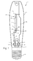
次に図面を参照する。図面は、単に代表的な実施形態を例示するものであり、実施形態を限定することは意図されていない。図1に、高圧ナトリウム・ランプ1を示す。高圧ナトリウム・ランプ1は、モノリシック発光管2を透明な外部のガラス質エンベロープ3内に配置した形式の高圧アルミナ放電蒸気アーク・チャンバを備える。発光管2には、加圧下で、アーク発生媒体または「充填物」7が含まれている。「充填物」7は、ナトリウムと、任意的に水銀と、出発ガス(たとえばキセノンまたは他の不活性ガス)とを含んでいる。電気的なニオブ・リード・ワイヤ4および5によって、電気エネルギーをタングステン電極6A、6Bに結合することができるようになっている。タングステン電極6A、6Bは、その上に電子放出材料を支持し、放電チャンバ2内に配置されて、放電チャンバ2内に含まれる充填物7を励起できるようになっている。密封用フリット(図示せず)によって、リード・ワイヤ4および5がアーク・チャンバ2の両端のアルミナに接合されている。密封は最初にリード・ワイヤ4において行なう。リード・ワイヤ5における密封は、アルミナ・ブッシング・フィードスル・アセンブリ7Aを用いて行なう。リード・ワイヤ4および5は、ネジ山の付いたねじ込み口金8に、支持部材15および16によって、またステム17を通って延びるリード・ワイヤ9および10において、電気的に接続されている。
Reference is now made to the drawings. The drawings are merely illustrative of exemplary embodiments and are not intended to limit the embodiments. A high pressure sodium lamp 1 is shown in FIG. The high-pressure sodium lamp 1 comprises a high-pressure alumina discharge vapor arc chamber of the type in which a
キセノン充填ガスは、冷却充填圧力が約10〜500トール(たとえば、約20〜200トール)であっても良い。動作中、キセノン圧力は、冷却充填圧力の約8倍まで増加しても良い。ナトリウムの分圧は、動作中に、30〜1000トールの範囲であり、たとえば、高効率を得るために約70〜150トールである。ランプ内のナトリウムの量は、70ワット・ランプに対して約5〜30mg(たとえば約12mg)であっても良く、また(無水銀ランプ以外において)アマルガム中のNa/Hgの比率は約10〜20%であっても良い。 The xenon fill gas may have a cooling fill pressure of about 10 to 500 Torr (eg, about 20 to 200 Torr). In operation, the xenon pressure may increase up to about 8 times the cooling fill pressure. Sodium partial pressure ranges from 30 to 1000 Torr during operation, for example, about 70 to 150 Torr for high efficiency. The amount of sodium in the lamp may be about 5-30 mg (eg about 12 mg) for a 70 watt lamp and the ratio of Na / Hg in the amalgam (except for anhydrous mercury lamps) is about 10-10. It may be 20%.
電極6A、6B間においてアーク放電を開始するには一般的に、開始電圧パルスとして約1.5〜4.5kVが必要である。この結果、出発ガスがイオン化されて、電流フローが開始され、その結果、発光管2内の温度が上がって、発光管2に含まれるナトリウムおよび水銀が蒸発する。その結果、アーク放電がイオン化蒸気によって維持されて、動作電圧が安定する。
In general, about 1.5 to 4.5 kV is required as a starting voltage pulse to start arc discharge between the
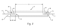
ランプ1はまた、ニオブ(Nb)箔の熱線反射バンド18を備えていても良い。熱線反射バンド18によって、ランプ基部の近くのアーク・チャンバ2の端部20における動作温度が、反対端22と比べて、高い値に維持される。その結果、金属ドーズ成分(すなわち、ナトリウムおよび水銀のアマルガム)の非蒸発量24が、図2に示すように動作中にアーク・チャンバ2の低温側端22に存在することになる。ランプ1のデザインは、液体ナトリウムが密封用フリットと接触することを防止して、寿命を限定する反応と始動中に整流(高バラスト電流)が生じる可能性とを回避するようになされている。
The lamp 1 may also include a heat ray
代表的な実施形態の一態様においては、発光管2内に含まれる充填物7は、ナトリウム、水銀、および出発ガス(たとえばキセノン)からなる。他の許容可能な出発ガスとしては、ガス・アーク放電を確立させるのに十分な任意の非反応性でイオン化可能なガス(たとえば希ガス)を挙げても良い。一実施形態においては、金属ドーズ(端部22におけるモノリシック・アルミナ隅部における)が、電極6Aをボディに対して密封した後に、モノリシック発光管ボディ内に導入される。キセノン出発ガスをその後、発光管内に密封する。これは、ブッシング7Aおよび電極6Bをボディの開口端に、キセノン雰囲気中で高温密封することによって行なう。
In one aspect of the exemplary embodiment, the fill 7 contained within the
図1には単端式のモノリシック・ランプを示しているが、他のランプ・形式も意図される。たとえば、両端式のランプおよび非モノリシック・ランプ(1つではなく2つのブッシングを用いて形成される)である。 Although FIG. 1 shows a single-ended monolithic lamp, other lamp types are contemplated. For example, double-ended lamps and non-monolithic lamps (formed with two bushings instead of one).
典型的な放電チャンバ2は主にアルミナで形成され、任意的に、ある量の他のセラミック酸化物(たとえば酸化マグネシウム)がドープされている。放電チャンバの主ボディは、当業者に知られている任意の手段によって構成することができる。たとえば、結合剤内のセラミック粉末の混合物を固体円筒内に金型プレスすることである。あるいは、混合物を押出成形することもできるし、射出成形することもできる。放電管の成形技術は知られており、たとえば、米国特許第1,639,362号明細書(スコットら)に記載されている通りである。
A
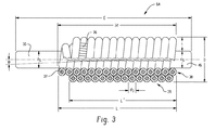
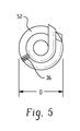
図3〜5および7〜9を参照して、電極6A、6Bはそれぞれ、直径dのタングステン・ロッド30の周りに直径Dおよび厚さt(外径マイナス内径)の巻き付けコイル32が設けられている形式のシャンクを備えている。巻き付けコイルに電子放出材料(放出体材料)34(図9)がコーティングされて、放出リザーバ35が形成されている。シャンク30は、発光管2内で略軸方向に配置され、コネクタにおけるリード線4、5と電気的に接続されている。電極6A、6Bのシャンク30によって、電極間のアーク間隙gが規定されている(図2)。
3-5 and 7-9,
好適な放出体材料は、バリウム含有酸化物および混合金属酸化物である、たとえばタングステン酸バリウムカルシウム、タングステン酸バリウムストロンチウム、タングステン酸バリウムイットリウム、タングステン酸バリウム、アルミン酸バリウムなどである。他の好適な放出材料には、金属酸化物であって、酸化物がLa、Ce、Pr、Nd、Pm、Sm、Eu、Gd、Tb、Dy、Ho、Er、Tm、Yb、Lu、Y、Sc、Hf、Zr、およびそれらの組み合わせの酸化物からなる群から選択される金属酸化物が含まれる。放出体材料は、列記したものに限定されないことを理解されたい。金属酸化物の存在量は、放出材料混合物全体の約20重量%〜100重量%の範囲である。放出材料34は、定常状態の動作条件の下で充填物の中で電子を放出するように動作可能である。
Suitable emitter materials are barium-containing oxides and mixed metal oxides, such as barium calcium tungstate, barium strontium tungstate, barium yttrium tungstate, barium tungstate, barium aluminate, and the like. Other suitable emission materials are metal oxides, where the oxides are La, Ce, Pr, Nd, Pm, Sm, Eu, Gd, Tb, Dy, Ho, Er, Tm, Yb, Lu, Y And metal oxides selected from the group consisting of oxides of Sc, Hf, Zr, and combinations thereof. It should be understood that the emitter materials are not limited to those listed. The amount of metal oxide present ranges from about 20% to 100% by weight of the total release material mixture. The
図3の部分断面図に示すように、巻き付けコイル32は1次のコイル構造と2次のコイル構造とを有している。1次のコイル構造は、上巻きワイヤ36を基本ワイヤ37の周りに巻くことによって形成される。2次のコイルは、1次のコイル構造をシャンク30の周りに巻くことによって形成される。図4に示すように、1次のコイル構造をぐるりと巻いてコイルにして、2つ(またはそれ以上)の重複層38、39を形成しても良い。2つの巻線38、39は、反対のピッチ角度θ(たとえば、約1.5度以下)と同じ巻数/インチ(TPI)とを有していても良い(図3)。2次のコイル構造を形成する層38、39は、図3に示すように、実質的に同一の広がりを持っていても良い。
As shown in the partial cross-sectional view of FIG. 3, the winding
一実施形態においては、基本ワイヤ37は直径d1が約0.05〜0.2mm(たとえば、約0.1mm)であり、上巻きワイヤ36は基本ワイヤよりも直径が小さくても良く、たとえば、直径d2が約0.01〜0.1mm(たとえば、約0.03〜0.04mm)であっても良い。したがって、結果として生じる1次のコイル構造は、直径d3が約d3=(2xd2)+d1、たとえば、約0.07〜0.4mm(たとえば、約0.2mm)である。2次のコイル構造は、約0.7mmのタングステン・シャンク30上に二重巻きしたときに、したがって、直径Dが約1.36mmとなる。これを、図3および5に示す。
In one embodiment, the
代表的な実施形態においては、上巻きワイヤ36は、厚さ(直径)d2が0.0346mmであり、直径d1が0.1056mmの基本ワイヤ37の周りに密に巻かれている。その結果、1次のコイル構造において、基本ワイヤ37上の上巻きワイヤ36のTPI(巻数/インチ)は、したがって、最大の理論値(実施例において419.86のTPI)であるかまたはそれに近い。たとえば、TPIは、理論上の最大値の少なくとも90%または少なくとも95%であっても良い。もっと低いTPIも意図される。たとえば、理論上の最大値の少なくとも60%または70%のTPIであり、これは、本実施例では、約250以上のTPIを意味するであろう。同様に、巻線を、第2のコイル構造の各層38、39において密に離間に配置して、第2のコイル構造におけるTPIとして理論上の最大値(本実施例では145.29のTPI)であるかまたはそれに近いものを提供しても良いが、より低いTPIを2次のコイル構造に対して用いても良い。たとえば、理論上の最大値の少なくとも約60%または70%のTPIであり、これは、本実施例では、約80以上のTPIを意味するであろう。
In the exemplary embodiment, the
応用例によっては、効果的に活性化することができる放出体材料の最大充填を達成することが望ましい。一実施形態においては、典型的な電極6A、6Bおよびそれらから形成されるランプは、同じコイル長さLおよび同じ電極直径Dの従来の二重巻き付けランプの場合よりも、少なくとも約20%(たとえば、約50%)多い放出体材料を支持する場合がある。ランプの寿命は、ある程度、放出体材料の量に依存するため、同じ直径のコイル上に支持することができる放出体の量が増加された結果、ランプの寿命を延ばすことができる。低いワット数のHPSランプに対する従来の発光管の直径は、電極直径に対して制約を課していた。典型的な電極は、より細い直径であるが、それにもかかわらず従来のコイルと同じ量の放出体混合物を保持することができる。その結果、ランプ寿命は、より高いワット数(より大きい直径)のランプのそれと同様である場合がある。
In some applications, it is desirable to achieve a maximum fill of emitter material that can be effectively activated. In one embodiment, the
しかし一般的に、直径Dを最小限にすることが望ましい場合がある。こうして、コイル32を、従来の二重コイル電極と同じかまたはより小さい直径Dを用いて形成することができる一方で、少なくとも同じかまたはより多い量の放出体材料を支持することができる。一実施形態においては、巻き付けコイル電極6A、6Bは、放出体材料の量が従来のランプ電極のそれとほぼ同じであっても良く、一方で直径Dが、従来の二重コイル電極の直径の約80%以下(たとえば、約50%)であっても良い。
In general, however, it may be desirable to minimize the diameter D. Thus, the
図6および7を比較することによって示されるように、直径が細い放出体リザーバ35を伴うランプの別の優位性は、従来の二重巻きコイル電極の放出体リザーバ35’(図6)と比べると、光(典型的な光線rによって示す)が、アーク40から低温箇所におけるアマルガム24まで直接進めることである(図7)。従来のリザーバ35’では、リザーバの直径が原因で、電極によって凝縮物質42のすべてまたはほとんどが直接光から隠されている。
As shown by comparing FIGS. 6 and 7, another advantage of a lamp with a narrow
巻き付けコイル電極6A、6Bの巻き付けコイル幾何学的形状を、図8および9に例示するように形成しても良い。1次のコイル構造50を最初に、ある長さのタングステン上巻きワイヤ36を、ある長さのタングステン基本ワイヤ37の周りに巻き付けることによって形成する。これによって、コイルの各巻数の幅、したがって1次のコイル直径が決定される(図8)。こうして形成した1次のコイル構造50を次に、電極シャンク30の周りに巻き付けて2次のコイル構造52を作製する。これを図9に示す。図9では、単一の(やや粗い)巻線の2次のコイル構造52のみを示しているが、図3に例示するように、2次のコイルは内部および外部の巻線38、39を有していても良いことを理解されたい。結果として生じる巻き付けコイル電極を、好適なアニール温度(たとえば、約1150℃)でアニールして、それほど電極構造を変えることなくワイヤ同士を固定しても良い。
The winding coil geometry of the winding
2次のコイル52は、シャンクに接触する結果、内径がシャンク直径によって規定される。2次のコイルの全長L(形成時)は、約2〜5mm(たとえば、約3mm)である。図3に示すように、外部の巻線39は内部の巻線38よりも長さがわずかに短くても良い。シャンク30は、直径d5が少なくとも約0.5mm(たとえば、約0.7mm)であっても良く、約0.5〜1mm(またはそれ以上)だけ巻き付けコイル32の外へ延びて電極先端46を規定しても良い。
As a result of the
典型的なワイヤ36、37およびシャンク30は、タングステンで形成されている。一般的に、それらは、主にタングステンから形成されている。すなわち、少なくとも70%タングステン、一般的には高純度タングステン(たとえば少なくとも99%タングステン)である。しかしアーク内で安定な他の電気伝導性材料も意図される。
放出体材料34を、巻き付けコイル32に、所望の酸化物の炭酸塩を含む粉末またはスラリの形態で塗布して、対応する酸化物にその場で転化することができる。ランプ・コイルにコーティングするために用いるスラリを作るために、炭酸塩粉末を混合して液体媒体と混合する。液体媒体は、ラッカーにおいて用いるものと同様であっても良く、有機溶媒(たとえば酢酸ブチルまたは他の低分子量酢酸塩)およびニトロセルロース(増粘剤および結合剤として用いる)からなっていても良い。他の構成成分(たとえばアルコール)を加えて所望の粘度を達成しても良い。たとえば、粉末状の炭酸塩に任意的に比較的少量の液体媒体を加えたものを混合器に加えて、電極6A、6Bを混合物中で振る。
The
表1に、種々のワット数のランプに対する典型的なシャンクおよびコイルの厚さを示す。 Table 1 shows typical shank and coil thicknesses for various wattage lamps.

一実施形態においては、ルーメン効率が、従来の二重コイル・ランプと比べて、8000時間において少なくとも約5%だけ増加する。その理由は、端部黒色化および電極損失が減ったからである。これにより、ランプに対するルーメン定格を改善できる場合がある。 In one embodiment, the lumen efficiency is increased by at least about 5% at 8000 hours compared to a conventional double coil lamp. The reason is that edge blackening and electrode loss are reduced. This may improve the lumen rating for the lamp.
ランプは、電圧上昇が低いことに起因して、信頼性が高くなる場合がある。たとえば、典型的なランプは14,000時間において約5Vの全体的な電圧上昇が起こる場合があり、これは、約2.5V/1000時間の電圧上昇が起こり得る既存のランプと比べて好都合である。 The lamp may be more reliable due to the lower voltage rise. For example, a typical lamp may have an overall voltage increase of about 5V at 14,000 hours, which is advantageous compared to existing lamps where a voltage increase of about 2.5V / 1000 hours can occur. is there.
従来のより低いワット数の形式(50〜100WのIECの形式)の刊行されているルーメン維持曲線は、すべての主なHPSランプ製造業者に対して、高ワット数の範囲の場合よりも低い。種々の態様において、典型的なランプでは、低ワット数の範囲(約100W未満、たとえば、50Wおよび70WのIECランプ)に対するルーメン維持定格が、より高いワット数のランプの場合と同様に高い場合がある。 The published lumen maintenance curve of the conventional lower wattage format (50-100 W IEC format) is lower for all major HPS lamp manufacturers than in the high wattage range. In various aspects, typical lamps may have a lumen maintenance rating for low wattage ranges (less than about 100 W, eg, 50 W and 70 W IEC lamps) as well as for higher wattage lamps. is there.
電極6A、6Bの応用例は、高圧ナトリウム放電ランプ、たとえば50/85;70/90;100/100W(標準およびXO)において、また35/52;50/52;および70/52ランプ・形式においても、さらにより高いワット数ランプに対しても見出される(なお、各対の1番目の数はワット数を表わし、2番目の数はランプ電圧を表す)。
Applications of
代表的な実施形態により形成されるランプに対する典型的なランプ特性は、表2に示すとおりである。 Typical lamp characteristics for lamps formed according to representative embodiments are shown in Table 2.
発光管端部の黒色化:これは、電極先端およびコイル・ボディの周りにおいて発光管の内壁表面上にスパッタリングおよび/または蒸着された電極材料(放出体材料、タングステン)によって形成される。
Arcing of the arc tube end: This is formed by electrode material (emitter material, tungsten) sputtered and / or deposited on the inner wall surface of the arc tube around the electrode tip and coil body.
電極スパッタリング:電極およびe混合物材料の除去が一般的に、正帯電イオンの衝突が原因で生じることが、開始プロセスの過渡現象の間に、アーク放電が安定するまで、またそれほどではないにせよ、定常状態のランプ動作の間に起こる。電極サイズがもっと大きくかつ混合物が不適切であると、スパッタリングを増大させる可能性があり、電極幾何学的形状とe混合物の種類および量とを最適化することによって、それを減らすことができる。 Electrode Sputtering: The removal of electrode and e-mixture material generally occurs due to collisions of positively charged ions until the arc discharge stabilizes and, to a lesser extent, during the initiation process transients, Occurs during steady state lamp operation. Larger electrode sizes and improper mixtures can increase sputtering, which can be reduced by optimizing the electrode geometry and the type and amount of e-mixture.
電極蒸発:電極およびe混合物材料が、電極先端およびコイル・ボディの動作温度が原因で蒸発する。小さい電極に対する蒸発速度は一般的に、直径が大きい電極の場合よりも大きい。 Electrode evaporation: The electrode and e-mixture material evaporates due to the operating temperature of the electrode tip and coil body. The evaporation rate for small electrodes is generally greater than for large diameter electrodes.
黒色化速度を小さくすることは、電極上の放出体材料の活性表面積を大きくすること、発光管の充填圧力を高くすること、電極幾何学的形状およびサイズを選択すること、ならびに放出体材料の種類および品質を選択することによって可能である。 Decreasing the blackening rate increases the active surface area of the emitter material on the electrode, increases the arc tube fill pressure, selects the electrode geometry and size, and the emitter material This is possible by selecting the type and quality.
既存の電極における問題の1つは、電極スケーリング・ルールによって、より低いワット数(たとえば、35〜100W)における放出リザーバの体積が限定されることである。その結果、ランプ寿命が制限される傾向がある。時間が経てば、放出体材料は通常、失われ、その結果、ルーメン維持が低下する。代表的な実施形態においては、このような制限は、電極巻線上でより小さい直径のワイヤの巻き付けコイル・デザインを用いることによって打開することができる。その結果、十分な重量の放出材料を保持することが、少なくともランプ寿命に渡って可能になる。 One problem with existing electrodes is that the electrode scaling rules limit the volume of the discharge reservoir at lower wattages (eg, 35-100 W). As a result, lamp life tends to be limited. Over time, emitter material is usually lost, resulting in reduced lumen maintenance. In the exemplary embodiment, such limitations can be overcome by using a smaller diameter wire wound coil design on the electrode windings. As a result, it is possible to retain a sufficient weight of released material at least over the lamp life.
代表的な実施形態の範囲を限定することを意図することなく、以下の実施例において、典型的なランプ・デザインの有効性を実証する。 Without intending to limit the scope of the exemplary embodiments, the following examples demonstrate the effectiveness of a typical lamp design.
電極を、表3に従って図3に例示するように形成した。形成は、タングステン上巻きワイヤ36を基本タングステン・ワイヤ37の周りに巻き付け、結果として生じる1次のコイル50をタングステン電極シャンク上に巻き付けて、コイルの2つの重複層38、39を有する2次のコイル構造52を形成することによって行なった。電極の全長Eは5.5mmであり、先端長さ(巻き付けコイルの外へ延びるシャンク)は0.8mmであった。他の寸法は以下の通りであった。L=2.8mm、L’=2.6mm、d3=0.01748mm、d5=0.70mm、θ=<1.5度。巻き付けコイル32を次にアニールした後、放出体材料(タングステン酸バリウムカルシウム)をコーティングした。放出体材料の量は、焼結後に約3mgであった。
Electrodes were formed according to Table 3 as illustrated in FIG. The formation is accomplished by winding a tungsten
ランプを、前述のように形成した電極からなる一対を、図2に従って、ルカロックス(Lucalox)(商標)モノリシック発光管2内に設けることによって形成した。発光管2内には、水銀/ナトリウムアマルガム(17重量%のNa、12mgのNa)とキセノン出発ガス(30mbarおよび250mbarの充填圧力)からなる充填物を含ませた。ランプは、70ワット(IEC)における公称動作に対してデザインした。
The lamp was formed by providing a pair of electrodes formed as described above in the Lucalox ™
図10に、こうして形成したランプのルーメン出力を、6000時間の一定動作をした後のある範囲の動作電圧に対して示す。30mbarの充填圧力における典型的な巻き付けコイル・ランプ(四角形)は、ルーメン出力が、同等な燃焼電圧における比較可能ランプ(三角形)よりも高い。典型的なランプは、標準的な二重コイル電極デザインの場合と同じコイル長さを用いて形成した。
FIG. 10 shows the lumen output of the lamp thus formed for a range of operating voltages after a constant operation of 6000 hours. A typical wound coil lamp (square) at a fill pressure of 30 mbar has a higher lumen output than a comparable lamp (triangle) at an equivalent combustion voltage. A typical lamp was formed using the same coil length as in a standard dual coil electrode design.
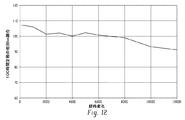
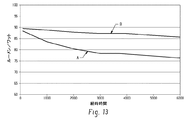
図11に、14000時間に渡る燃焼電圧を、30mbarの冷却充填圧力における10個の典型的なランプに対して示すとともに、6000時間に渡る比較ランプに対して示す。図に示すように、典型的なランプは、BV維持が14000時間に渡って安定している。図12に、典型的なルーメン維持値(100時間における割合としてのルーメン)を、巻き付けコイルを伴う典型的なランプに対して、12000時間の試験に渡って示す。典型的なランプは、ルーメン維持が優れており、標準的な二重コイル電極デザインよりも6000時間において約10%高いlm/Wである。図13に、ルーメン/ワットの時間経過を、標準的な二重巻き付け電極を伴う比較の70ワット・ランプ(曲線A)と、代表的な実施形態による70ワット・ランプ(曲線B)とに対して示す。
巻き付けコイル・デザインの優位性
巻き付けコイル電極デザインについて前述した結果に示すように、形成したランプは、試験時間に渡ってBVおよびルーメン維持性能が優れている。巻き付けコイル・デザインの他の優位性は、以下のようであっても良い。同じ量の放出体を伴う比較可能な二重コイル・ランプと比べてコイル・ボディが軽いために、端部損失が減ることにより初期lm/W(効率)が向上する。黒色化速度が遅いことによるルーメン維持の向上(おおよその損失は約1%/1000時間)。バックスペース(MK)感度が低いために、発光管が生産変動の影響を受けにくくなる。電極および支配的なアーク熱からの熱放射が減ることにより、Tcが安定化する。コイル・ボディが小さくて軽くなったために、標準的な電極の場合と同じe混合物量を、変動が小さい状態で含むことができる。黒色化が減ったことにより、ルーメン維持が良好になる(8000時間に渡って)。発光管幾何学的形状(穴サイズおよび肉厚)を最適化することができる。
FIG. 11 shows the combustion voltage over 14000 hours for 10 typical lamps at 30 mbar cold fill pressure and for a comparative lamp over 6000 hours. As shown, a typical lamp has a stable BV maintenance for 14000 hours. FIG. 12 shows typical lumen maintenance values (lumens as a percentage in 100 hours) over a 12000 hour test for a typical lamp with a wound coil. A typical lamp has better lumen maintenance and is about 10% higher lm / W at 6000 hours than a standard dual coil electrode design. FIG. 13 shows the lumen / watt time course for a comparative 70 watt lamp (curve A) with a standard double wound electrode and a 70 watt lamp (curve B) according to a representative embodiment. Show.
Advantages of Wound Coil Design As shown in the results described above for the wound coil electrode design, the lamp formed has excellent BV and lumen maintenance performance over the test time. Other advantages of the wound coil design may be as follows. The initial lm / W (efficiency) is improved by reducing the end loss due to the lighter coil body compared to a comparable dual coil lamp with the same amount of emitter. Improved lumen maintenance due to slow blackening rate (approximately 1% / 1000 hours loss). Since the back space (MK) sensitivity is low, the arc tube is less susceptible to production fluctuations. Tc is stabilized by reducing the heat radiation from the electrodes and the dominant arc heat. Because the coil body is smaller and lighter, it can contain the same amount of e-mixture as with standard electrodes, with little variation. Less blackening results in better lumen maintenance (over 8000 hours). The arc tube geometry (hole size and wall thickness) can be optimized.
本発明を、好ましい実施形態を参照して説明してきた。明らかに、前述の詳細な説明を読んで理解することによって、変更および修正が他のものに対して想起される。本発明をこのような変更および修正をすべて含むものと解釈すべきであることが意図されている。 The invention has been described with reference to the preferred embodiments. Obviously, changes and modifications will occur to others upon reading and understanding the foregoing detailed description. It is intended that the present invention should be construed to include all such changes and modifications.
Claims (22)
ランプの動作中に充填物内でアーク放電を起こすために充填物内に延びる電極であって、少なくとも1つの電極は、その上に放出体材料を支持する巻き付けコイルを備えている、電極と、を備える高圧ナトリウム放電ランプ。 An arc tube enclosing a discharge sustaining filler containing sodium;
An electrode extending into the fill to cause arcing in the fill during lamp operation, the at least one electrode comprising a wound coil supporting the emitter material thereon; High pressure sodium discharge lamp.
基本ワイヤの周りに上巻きワイヤを巻き付けることによって電極の第1のコイル構造を形成することと、
シャンクの周りに第1のコイル構造を巻き付けることによって前記電極の第2のコイル構造を形成することと、
前記電極に放出体材料をコーティングすることと、
前記電極を第2の電極とともに発光管内に挿入することと、
ナトリウムを含む放電維持充填物を発光管内に密封することと、を含む方法。 A method of forming a high pressure discharge lamp, comprising:
Forming a first coil structure of the electrode by winding an overwound wire around the basic wire;
Forming a second coil structure of the electrode by wrapping the first coil structure around the shank;
Coating the electrode with an emitter material;
Inserting the electrode together with a second electrode into the arc tube;
Sealing a discharge sustaining fill comprising sodium within the arc tube.
タングステン・シャンク上に設けられる巻き付けコイルであって、基本ワイヤの周りに電気伝導性の上巻きワイヤを巻き付けることによって形成される第1のコイル構造と、シャンクの周りに第1のコイル構造を巻き付けることによって形成される第2のコイル構造とを有する巻き付けコイルと、
巻き付けコイル上に支持される放出体材料と、を備える電極。 A cylindrical tungsten shank with a diameter of 0.5-2 mm for coupling with a current source;
A winding coil provided on a tungsten shank, wherein the first coil structure is formed by winding an electrically conductive upper winding wire around the basic wire, and the first coil structure is wound around the shank. A wound coil having a second coil structure formed by
An emitter material supported on the winding coil.
Applications Claiming Priority (3)
| Application Number | Priority Date | Filing Date | Title |
|---|---|---|---|
| US95237107P | 2007-07-27 | 2007-07-27 | |
| US12/147,979 US20090026956A1 (en) | 2007-07-27 | 2008-06-27 | Coiled coil electrode design for high pressure sodium lamps |
| PCT/US2008/070301 WO2009017975A1 (en) | 2007-07-27 | 2008-07-17 | Coiled coil electrode design for high pressure sodium lamps |
Publications (2)
| Publication Number | Publication Date |
|---|---|
| JP2010534914A true JP2010534914A (en) | 2010-11-11 |
| JP2010534914A5 JP2010534914A5 (en) | 2012-08-23 |
Family
ID=40294688
Family Applications (1)
| Application Number | Title | Priority Date | Filing Date |
|---|---|---|---|
| JP2010518300A Pending JP2010534914A (en) | 2007-07-27 | 2008-07-17 | Wound coil electrode design for high pressure sodium lamp |
Country Status (5)
| Country | Link |
|---|---|
| US (1) | US20090026956A1 (en) |
| EP (1) | EP2183762A1 (en) |
| JP (1) | JP2010534914A (en) |
| CN (1) | CN101802969A (en) |
| WO (1) | WO2009017975A1 (en) |
Families Citing this family (2)
| Publication number | Priority date | Publication date | Assignee | Title |
|---|---|---|---|---|
| DE102011077302A1 (en) * | 2011-06-09 | 2012-12-13 | Osram Ag | High pressure discharge lamp |
| CN111725039B (en) * | 2019-03-20 | 2023-03-31 | 上海亚尔精密零件制造有限公司 | Method for manufacturing electrode spring of high-power gas discharge lamp |
Citations (9)
| Publication number | Priority date | Publication date | Assignee | Title |
|---|---|---|---|---|
| JPS5457375A (en) * | 1977-10-14 | 1979-05-09 | Hitachi Ltd | High-pressure sodium vapor lamp |
| JPS5676156A (en) * | 1979-11-24 | 1981-06-23 | Matsushita Electronics Corp | High-pressure sodium-vapor lamp |
| JPS58166629A (en) * | 1982-03-29 | 1983-10-01 | Matsushita Electronics Corp | High pressure sodium lamp |
| JPS59171447A (en) * | 1983-03-18 | 1984-09-27 | Mitsubishi Electric Corp | Electrode for discharge lamp |
| JPS59214152A (en) * | 1983-05-18 | 1984-12-04 | Matsushita Electronics Corp | High-pressure sodium lamp |
| JPH01143137A (en) * | 1987-11-30 | 1989-06-05 | Toshiba Corp | High-pressure sodium lamp |
| JPH03108250A (en) * | 1989-09-20 | 1991-05-08 | Toshiba Lighting & Technol Corp | Ceramic discharge lamp |
| JPH04303547A (en) * | 1991-03-29 | 1992-10-27 | Toshiba Lighting & Technol Corp | Metallic vapor discharge lamp |
| JPH08264156A (en) * | 1995-03-22 | 1996-10-11 | Toshiba Lighting & Technol Corp | Ceramic discharge lamp, its lighting device and lighting system |
Family Cites Families (6)
| Publication number | Priority date | Publication date | Assignee | Title |
|---|---|---|---|---|
| US3761758A (en) * | 1972-01-27 | 1973-09-25 | Gte Sylvania Inc | Metal halide lamp containing mercury, light emitting metal, sodium and another alkali metal |
| US4277714A (en) * | 1979-07-02 | 1981-07-07 | Gte Products Corporation | Metal halide arc discharge lamp having coiled coil electrodes |
| JPS57152657A (en) * | 1981-03-16 | 1982-09-21 | Toshiba Corp | High pressure sodium lamp |
| JPS60264040A (en) * | 1984-06-12 | 1985-12-27 | Matsushita Electronics Corp | High pressure sodium lamp |
| US6157132A (en) * | 1998-08-19 | 2000-12-05 | General Electric Company | Discharge lamp emission material |
| US6639362B1 (en) * | 2000-11-06 | 2003-10-28 | General Electric Company | High pressure discharge lamp |
-
2008
- 2008-06-27 US US12/147,979 patent/US20090026956A1/en not_active Abandoned
- 2008-07-17 EP EP08781965A patent/EP2183762A1/en not_active Withdrawn
- 2008-07-17 JP JP2010518300A patent/JP2010534914A/en active Pending
- 2008-07-17 CN CN200880108272A patent/CN101802969A/en active Pending
- 2008-07-17 WO PCT/US2008/070301 patent/WO2009017975A1/en active Application Filing
Patent Citations (9)
| Publication number | Priority date | Publication date | Assignee | Title |
|---|---|---|---|---|
| JPS5457375A (en) * | 1977-10-14 | 1979-05-09 | Hitachi Ltd | High-pressure sodium vapor lamp |
| JPS5676156A (en) * | 1979-11-24 | 1981-06-23 | Matsushita Electronics Corp | High-pressure sodium-vapor lamp |
| JPS58166629A (en) * | 1982-03-29 | 1983-10-01 | Matsushita Electronics Corp | High pressure sodium lamp |
| JPS59171447A (en) * | 1983-03-18 | 1984-09-27 | Mitsubishi Electric Corp | Electrode for discharge lamp |
| JPS59214152A (en) * | 1983-05-18 | 1984-12-04 | Matsushita Electronics Corp | High-pressure sodium lamp |
| JPH01143137A (en) * | 1987-11-30 | 1989-06-05 | Toshiba Corp | High-pressure sodium lamp |
| JPH03108250A (en) * | 1989-09-20 | 1991-05-08 | Toshiba Lighting & Technol Corp | Ceramic discharge lamp |
| JPH04303547A (en) * | 1991-03-29 | 1992-10-27 | Toshiba Lighting & Technol Corp | Metallic vapor discharge lamp |
| JPH08264156A (en) * | 1995-03-22 | 1996-10-11 | Toshiba Lighting & Technol Corp | Ceramic discharge lamp, its lighting device and lighting system |
Also Published As
| Publication number | Publication date |
|---|---|
| US20090026956A1 (en) | 2009-01-29 |
| EP2183762A1 (en) | 2010-05-12 |
| CN101802969A (en) | 2010-08-11 |
| WO2009017975A1 (en) | 2009-02-05 |
Similar Documents
| Publication | Publication Date | Title |
|---|---|---|
| JP5138606B2 (en) | Ceramic metal halide lamp | |
| JP5020806B2 (en) | Optimal shape ceramic metal halide lamp | |
| US20060290285A1 (en) | Rapid Warm-up Ceramic Metal Halide Lamp | |
| JP2008053237A (en) | Metal halide lamp | |
| JP4279122B2 (en) | High pressure discharge lamp and lighting device | |
| JP2003086133A (en) | High pressure discharge lamp and high pressure discharge lamp system using it | |
| JPS647460B2 (en) | ||
| JP2010534914A (en) | Wound coil electrode design for high pressure sodium lamp | |
| US7423379B2 (en) | High-pressure gas discharge lamp having tubular electrodes | |
| US20080007178A1 (en) | Metal Halide Lamp and Illuminating Device Using the Same | |
| JP5190582B2 (en) | Metal halide lamps and lighting fixtures | |
| US4910433A (en) | Emitterless SDN electrode | |
| JPS644305B2 (en) | ||
| JP2002515636A (en) | Low pressure mercury vapor discharge lamp | |
| US4639639A (en) | High-pressure sodium vapor lamp and ternary amalgam therefor | |
| WO2009119612A1 (en) | High-pressure discharge lamp and lighting device | |
| JP2005285672A (en) | High pressure discharge lamp | |
| JP2010140826A (en) | High-pressure discharge lamp, and lighting system | |
| US20110291556A1 (en) | Gas discharge lamp | |
| JPH0357576B2 (en) | ||
| JPH02230652A (en) | Low pressure discharge lamp | |
| JPH11329347A (en) | Discharge lamp and its manufacture | |
| JPH0883594A (en) | Unsaturated vapor pressure high pressure sodium lamp | |
| JPH0626110B2 (en) | High color rendering high pressure sodium lamp | |
| JPH04308643A (en) | Low pressure discharge lamp |
Legal Events
| Date | Code | Title | Description |
|---|---|---|---|
| A521 | Request for written amendment filed |
Free format text: JAPANESE INTERMEDIATE CODE: A523 Effective date: 20110704 |
|
| A621 | Written request for application examination |
Free format text: JAPANESE INTERMEDIATE CODE: A621 Effective date: 20110704 |
|
| A521 | Request for written amendment filed |
Free format text: JAPANESE INTERMEDIATE CODE: A523 Effective date: 20120629 |
|
| A977 | Report on retrieval |
Free format text: JAPANESE INTERMEDIATE CODE: A971007 Effective date: 20121228 |
|
| A131 | Notification of reasons for refusal |
Free format text: JAPANESE INTERMEDIATE CODE: A131 Effective date: 20130108 |
|
| A601 | Written request for extension of time |
Free format text: JAPANESE INTERMEDIATE CODE: A601 Effective date: 20130408 |
|
| A602 | Written permission of extension of time |
Free format text: JAPANESE INTERMEDIATE CODE: A602 Effective date: 20130418 |
|
| A521 | Request for written amendment filed |
Free format text: JAPANESE INTERMEDIATE CODE: A523 Effective date: 20130708 |
|
| A131 | Notification of reasons for refusal |
Free format text: JAPANESE INTERMEDIATE CODE: A131 Effective date: 20140304 |
|
| A02 | Decision of refusal |
Free format text: JAPANESE INTERMEDIATE CODE: A02 Effective date: 20140812 |