JP2010529353A - Internal combustion engine - Google Patents
Internal combustion engine Download PDFInfo
- Publication number
- JP2010529353A JP2010529353A JP2010510866A JP2010510866A JP2010529353A JP 2010529353 A JP2010529353 A JP 2010529353A JP 2010510866 A JP2010510866 A JP 2010510866A JP 2010510866 A JP2010510866 A JP 2010510866A JP 2010529353 A JP2010529353 A JP 2010529353A
- Authority
- JP
- Japan
- Prior art keywords
- crankshaft
- piston
- cylinder
- engine
- journal
- Prior art date
- Legal status (The legal status is an assumption and is not a legal conclusion. Google has not performed a legal analysis and makes no representation as to the accuracy of the status listed.)
- Pending
Links
Images


Classifications
-
- F—MECHANICAL ENGINEERING; LIGHTING; HEATING; WEAPONS; BLASTING
- F01—MACHINES OR ENGINES IN GENERAL; ENGINE PLANTS IN GENERAL; STEAM ENGINES
- F01B—MACHINES OR ENGINES, IN GENERAL OR OF POSITIVE-DISPLACEMENT TYPE, e.g. STEAM ENGINES
- F01B9/00—Reciprocating-piston machines or engines characterised by connections between pistons and main shafts and not specific to preceding groups
- F01B9/02—Reciprocating-piston machines or engines characterised by connections between pistons and main shafts and not specific to preceding groups with crankshaft
- F01B9/023—Reciprocating-piston machines or engines characterised by connections between pistons and main shafts and not specific to preceding groups with crankshaft of Bourke-type or Scotch yoke
-
- F—MECHANICAL ENGINEERING; LIGHTING; HEATING; WEAPONS; BLASTING
- F01—MACHINES OR ENGINES IN GENERAL; ENGINE PLANTS IN GENERAL; STEAM ENGINES
- F01B—MACHINES OR ENGINES, IN GENERAL OR OF POSITIVE-DISPLACEMENT TYPE, e.g. STEAM ENGINES
- F01B1/00—Reciprocating-piston machines or engines characterised by number or relative disposition of cylinders or by being built-up from separate cylinder-crankcase elements
- F01B1/08—Reciprocating-piston machines or engines characterised by number or relative disposition of cylinders or by being built-up from separate cylinder-crankcase elements with cylinders arranged oppositely relative to main shaft and of "flat" type
-
- F—MECHANICAL ENGINEERING; LIGHTING; HEATING; WEAPONS; BLASTING
- F01—MACHINES OR ENGINES IN GENERAL; ENGINE PLANTS IN GENERAL; STEAM ENGINES
- F01B—MACHINES OR ENGINES, IN GENERAL OR OF POSITIVE-DISPLACEMENT TYPE, e.g. STEAM ENGINES
- F01B7/00—Machines or engines with two or more pistons reciprocating within same cylinder or within essentially coaxial cylinders
- F01B7/02—Machines or engines with two or more pistons reciprocating within same cylinder or within essentially coaxial cylinders with oppositely reciprocating pistons
- F01B7/04—Machines or engines with two or more pistons reciprocating within same cylinder or within essentially coaxial cylinders with oppositely reciprocating pistons acting on same main shaft
- F01B7/06—Machines or engines with two or more pistons reciprocating within same cylinder or within essentially coaxial cylinders with oppositely reciprocating pistons acting on same main shaft using only connecting-rods for conversion of reciprocatory into rotary motion or vice versa
- F01B7/10—Machines or engines with two or more pistons reciprocating within same cylinder or within essentially coaxial cylinders with oppositely reciprocating pistons acting on same main shaft using only connecting-rods for conversion of reciprocatory into rotary motion or vice versa having piston-rod of one piston passed through other piston
-
- F—MECHANICAL ENGINEERING; LIGHTING; HEATING; WEAPONS; BLASTING
- F02—COMBUSTION ENGINES; HOT-GAS OR COMBUSTION-PRODUCT ENGINE PLANTS
- F02B—INTERNAL-COMBUSTION PISTON ENGINES; COMBUSTION ENGINES IN GENERAL
- F02B25/00—Engines characterised by using fresh charge for scavenging cylinders
- F02B25/02—Engines characterised by using fresh charge for scavenging cylinders using unidirectional scavenging
- F02B25/08—Engines with oppositely-moving reciprocating working pistons
-
- F—MECHANICAL ENGINEERING; LIGHTING; HEATING; WEAPONS; BLASTING
- F02—COMBUSTION ENGINES; HOT-GAS OR COMBUSTION-PRODUCT ENGINE PLANTS
- F02B—INTERNAL-COMBUSTION PISTON ENGINES; COMBUSTION ENGINES IN GENERAL
- F02B75/00—Other engines
- F02B75/16—Engines characterised by number of cylinders, e.g. single-cylinder engines
- F02B75/18—Multi-cylinder engines
- F02B75/24—Multi-cylinder engines with cylinders arranged oppositely relative to main shaft and of "flat" type
-
- F—MECHANICAL ENGINEERING; LIGHTING; HEATING; WEAPONS; BLASTING
- F02—COMBUSTION ENGINES; HOT-GAS OR COMBUSTION-PRODUCT ENGINE PLANTS
- F02B—INTERNAL-COMBUSTION PISTON ENGINES; COMBUSTION ENGINES IN GENERAL
- F02B75/00—Other engines
- F02B75/28—Engines with two or more pistons reciprocating within same cylinder or within essentially coaxial cylinders
-
- F—MECHANICAL ENGINEERING; LIGHTING; HEATING; WEAPONS; BLASTING
- F02—COMBUSTION ENGINES; HOT-GAS OR COMBUSTION-PRODUCT ENGINE PLANTS
- F02B—INTERNAL-COMBUSTION PISTON ENGINES; COMBUSTION ENGINES IN GENERAL
- F02B75/00—Other engines
- F02B75/32—Engines characterised by connections between pistons and main shafts and not specific to preceding main groups
-
- F—MECHANICAL ENGINEERING; LIGHTING; HEATING; WEAPONS; BLASTING
- F02—COMBUSTION ENGINES; HOT-GAS OR COMBUSTION-PRODUCT ENGINE PLANTS
- F02B—INTERNAL-COMBUSTION PISTON ENGINES; COMBUSTION ENGINES IN GENERAL
- F02B75/00—Other engines
- F02B75/02—Engines characterised by their cycles, e.g. six-stroke
- F02B2075/022—Engines characterised by their cycles, e.g. six-stroke having less than six strokes per cycle
- F02B2075/025—Engines characterised by their cycles, e.g. six-stroke having less than six strokes per cycle two
-
- F—MECHANICAL ENGINEERING; LIGHTING; HEATING; WEAPONS; BLASTING
- F02—COMBUSTION ENGINES; HOT-GAS OR COMBUSTION-PRODUCT ENGINE PLANTS
- F02B—INTERNAL-COMBUSTION PISTON ENGINES; COMBUSTION ENGINES IN GENERAL
- F02B75/00—Other engines
- F02B75/16—Engines characterised by number of cylinders, e.g. single-cylinder engines
- F02B75/18—Multi-cylinder engines
- F02B2075/1804—Number of cylinders
- F02B2075/1808—Number of cylinders two
-
- F—MECHANICAL ENGINEERING; LIGHTING; HEATING; WEAPONS; BLASTING
- F02—COMBUSTION ENGINES; HOT-GAS OR COMBUSTION-PRODUCT ENGINE PLANTS
- F02B—INTERNAL-COMBUSTION PISTON ENGINES; COMBUSTION ENGINES IN GENERAL
- F02B2275/00—Other engines, components or details, not provided for in other groups of this subclass
- F02B2275/40—Squish effect
-
- F—MECHANICAL ENGINEERING; LIGHTING; HEATING; WEAPONS; BLASTING
- F02—COMBUSTION ENGINES; HOT-GAS OR COMBUSTION-PRODUCT ENGINE PLANTS
- F02F—CYLINDERS, PISTONS OR CASINGS, FOR COMBUSTION ENGINES; ARRANGEMENTS OF SEALINGS IN COMBUSTION ENGINES
- F02F1/00—Cylinders; Cylinder heads
- F02F1/18—Other cylinders
- F02F1/22—Other cylinders characterised by having ports in cylinder wall for scavenging or charging
-
- F—MECHANICAL ENGINEERING; LIGHTING; HEATING; WEAPONS; BLASTING
- F02—COMBUSTION ENGINES; HOT-GAS OR COMBUSTION-PRODUCT ENGINE PLANTS
- F02F—CYLINDERS, PISTONS OR CASINGS, FOR COMBUSTION ENGINES; ARRANGEMENTS OF SEALINGS IN COMBUSTION ENGINES
- F02F3/00—Pistons
- F02F3/0015—Multi-part pistons
-
- Y—GENERAL TAGGING OF NEW TECHNOLOGICAL DEVELOPMENTS; GENERAL TAGGING OF CROSS-SECTIONAL TECHNOLOGIES SPANNING OVER SEVERAL SECTIONS OF THE IPC; TECHNICAL SUBJECTS COVERED BY FORMER USPC CROSS-REFERENCE ART COLLECTIONS [XRACs] AND DIGESTS
- Y02—TECHNOLOGIES OR APPLICATIONS FOR MITIGATION OR ADAPTATION AGAINST CLIMATE CHANGE
- Y02T—CLIMATE CHANGE MITIGATION TECHNOLOGIES RELATED TO TRANSPORTATION
- Y02T10/00—Road transport of goods or passengers
- Y02T10/10—Internal combustion engine [ICE] based vehicles
- Y02T10/12—Improving ICE efficiencies
Abstract
本発明は2つの対向ピストンを具備した2ストロークエンジンを供給している。各々のシリンダは2つの対向したピストンを収容し、少なくとも2つの排気ポートと少なくとも2つの吸気ポートと、ジャーナルに非対称に連結されたクランクシャフトと、ピストンからジャーナルを駆動するためのスコッチヨーク機構とを備えている。各々のシリンダ内のピストンは1つまたは複数の排気ポートを1つまたは複数の吸気ポートが開く前に開くように作動し、1つまたは複数の排気ポートを1つまたは複数の吸気ポートが閉じる前に閉じるように作動する。 The present invention provides a two-stroke engine with two opposed pistons. Each cylinder houses two opposing pistons, and has at least two exhaust ports, at least two intake ports, a crankshaft asymmetrically connected to the journal, and a Scotch yoke mechanism for driving the journal from the piston. I have. The piston in each cylinder operates to open one or more exhaust ports before the one or more intake ports open and before one or more exhaust ports are closed by one or more intake ports Operates to close.
Description
本発明は内燃エンジンに関する。より具体的には、本発明は対向ピストンおよび対向シリンダ(POCO)形態を備えた内燃エンジンに関する。 The present invention relates to an internal combustion engine. More specifically, the present invention relates to an internal combustion engine having opposed piston and opposed cylinder (POCO) configurations.
内燃エンジンは第二次世界大戦の終結依頼非常にわずかな変更しか受けておらず、ほぼ世界中において今日使用されているピストンエンジンは、第2次世界大戦中に行われた発展よりも第2次世界大戦の勃発時における設計慣習のほうがより一般的であるということが論証できる。 The internal combustion engine has undergone very little changes to the end of World War II, and the piston engines used today almost all over the world are second to the developments made during World War II. It can be demonstrated that the design practice at the outbreak of World War II is more general.
戦争の終結に伴って、要求は、安価且つ容易に生産できるもの、特に進化した機械加工技術または非標準的な材料を必要としないものとなった。当時は、内燃エンジンは別の技術が支配するまでの一時凌ぎの技術に過ぎず、この仮説は10年ごとに繰り返し唱えられてきた。 With the end of the war, the requirements became cheap and easy to produce, especially those that did not require advanced machining techniques or non-standard materials. At that time, the internal combustion engine was only a technology that surpassed until another technology ruled, and this hypothesis has been reiterated every ten years.
ロータリーエンジンは軍事的開発後の多数のもののうちの1つである。ロータリーエンジンの基本的な幾何形状は蒸気時代から現存しているが、その動作は生存に適した解決方法を提案した点にまで持ち込んだフェリックス・ヴァンケルによって成された。従来型の内燃エンジンと比較して、ヴァンケルエンジンは与えられた容量よりもはるかに小さく、無振動運転に近いという追加的な利点を提供した。10年の終わりまでに、ほとんどすべての大手エンジン製作者はWankel Instituteからライセンスを購入し、ロータリーエンジンを生産したが、問題がすぐに明確になった。第1に、この問題は最終的には解消されたが、ローターチップの脆弱なシールは多くの製品の生産後のみにリコールされたが、保証要求は先進的な生産者を倒産寸前に追い込んだ。第2は基本設計における先天的なものである。ヴァンケルエンジン内の回転ローターとチャンバ壁との形状は、燃焼容積が燃焼する間際のローターとチャンバとの間に使い残されることを強要する。このことは大きい領域/容積比(area/volume ratio)および非効率的な形状によって不完全燃焼を引き起こす。少ない燃費は、世界が1974年の第1次オイルショックになるまでともに暮らしえることを教わったが、ヴァンケルエンジンはマツダを除いて全ての大手の生産者からあきらめられた。少ない燃費と同じくらい今日重要な排ガスを伴って、ヴァンケルの非効率的なエンジンは、ユーザが小型且つスムーズな特性と引き換えにこれらの欠陥を容認することが可能なアプリケーションを除いては、将来任意の重要な役割を担うとは考えられない。 The rotary engine is one of many after military development. The basic geometry of the rotary engine has existed since the steam age, but its operation was made by Felix Wankel who brought it to the point where he proposed a solution suitable for survival. Compared to a conventional internal combustion engine, the Wankel engine offers the additional advantage of being much smaller than the given capacity and close to vibration-free operation. By the end of the decade, almost all major engine builders purchased licenses from the Wankel Institute and produced rotary engines, but the problem quickly became clear. First, the problem was eventually eliminated, but the fragile seal of the rotor tip was recalled only after many products were produced, but the warranty requirement pushed advanced producers to the point of bankruptcy. . The second is innate in basic design. The shape of the rotating rotor and chamber wall in the Wankel engine forces the combustion volume to be left over between the rotor and chamber just before burning. This causes incomplete combustion due to the large area / volume ratio and inefficient shape. Low fuel consumption was taught that the world could live together until the 1974 first oil shock, but the Wankel engine was given up by all major producers except Mazda. With today's emissions as important as low fuel consumption, Wankel's inefficient engines are optional in the future, except for applications where users can tolerate these deficiencies in exchange for small and smooth characteristics. It is not considered to play an important role.
それらはひどい目にあい、生産者は従来型のエンジンへと回帰し、将来の動力源として受け入れられるものの進化を待っていた。それは燃料電池である。進化したバッテリの開発も継続中であるが、このとき第1の商用電気自動車が現実的に予期され得るものであったことは皮肉なことであり、内燃エンジンが長年にわたって高効率な自動車専用のまたはハイブリッド伝動機構としての重要な未来を有していること実感が育っている。 They were terrible and the producers returned to traditional engines and awaited the evolution of what could be accepted as a future power source. It is a fuel cell. The development of an advanced battery is ongoing, but it is ironic that the first commercial electric vehicle could be realistically anticipated at this time, and the internal combustion engine has been dedicated to highly efficient vehicles for many years. Or, I feel that I have an important future as a hybrid transmission mechanism.
ある観点では、商業的使用のためのディーゼルエンジンの設計者は対向ピストン2ストロークエンジンにより多くの利点を備え、そのエンジンは1930年代にJunkers Jumoとして、ならびに1950年代および60年代にNapier DelticおよびCommer TS3としてドイツで開発された。 In one aspect, designers of diesel engines for commercial use have many advantages over opposed piston two-stroke engines, which are Junkers Jumo in the 1930s and Napier Deltic and Commer TS3 in the 1950s and 1960s. Developed in Germany.
近代ピストンエンジンの要求を構築する場合、問題はどのような特徴を備えるべきであるかということである。 When building the requirements of a modern piston engine, the question is what characteristics should be provided.
生産の効率化および現実的な使用の理由のために、エンジンは最小限の可動部品を備えて極力単純のものであるべきである。極力小さく、容易に適応されて自動車の駆動、パッケージの改良、歩行者安全性の強化、より容易なハイブリッド伝動機構への組み込みが行われる。 For reasons of production efficiency and practical use, the engine should be as simple as possible with a minimum of moving parts. Minimal and easily adapted to drive cars, improve packaging, enhance pedestrian safety, and incorporate into easier hybrid transmission mechanisms.
エンジンは軽量であり、最小エネルギは自身の質量を移動することに使用される一方で、固定された自動車の総重量以内でより大きな最大積載量を可能とする。 The engine is lightweight and the minimum energy is used to move its mass, while allowing a greater maximum load within the total weight of the fixed vehicle.
同世代のエンジンよりもより良好な燃費で使用され、それはより良好な燃焼、少ない内部摩擦および往復する塊が減少されていることを意味する。 Used with better fuel economy than the same generation engine, which means better combustion, less internal friction and reduced reciprocating mass.
可能であれば、無振動で自動車乗員の快適性を改善し、車室内のストレスを減少させる。 If possible, improve passenger comfort without vibration and reduce stress in the passenger compartment.
理論上は、2ストロークエンジンはそのサイズに関してより大きな出力を達成することにおいて利点があり、それは各々のシリンダが各回転で出力を生み出すためである。しかしながら、この潜在能力は、過度の吸気および排気工程が重なり合うことによって障害が起き、実際のところ対向ピストン2ストロークエンジンは最も効率的な燃焼を達成するためにもともと最適化された非対称性を備えていない。燃費の利点は燃料噴射システムとエンジン管理手段とから得られ、この多くはより清浄なエンジンが現れることで克服され得る。 Theoretically, a two-stroke engine has an advantage in achieving greater power with respect to its size, because each cylinder produces power at each revolution. However, this potential is hampered by the overlap of excessive intake and exhaust processes, and in fact, opposed piston two-stroke engines have inherently optimized asymmetry to achieve the most efficient combustion. Absent. Fuel economy benefits are gained from the fuel injection system and engine management means, many of which can be overcome by the appearance of cleaner engines.
対向シリンダを備え、各々のシリンダが共通の中央クランクシャフトに連結された一組の対向ピストンを備えた2ストローク内燃エンジンは、Hofbauerの特許文献1に開示されている。クランクシャフトの偏心器の角度位置の独立性は吸気および排気ポートの非対称タイミングを可能にし、これによって吸気および排気ポートの重なりを最適化している。初期的な動的不均衡に起因したその影響は、移動する部品の幾何形状および質量を複雑な方式において制御することによって最小化される。 A two-stroke internal combustion engine comprising a pair of opposed pistons with opposed cylinders, each cylinder connected to a common central crankshaft is disclosed in US Pat. Independence of the angular position of the crankshaft eccentric allows for asymmetric timing of the intake and exhaust ports, thereby optimizing the overlap of the intake and exhaust ports. Its effect due to the initial dynamic imbalance is minimized by controlling the geometry and mass of the moving parts in a complex manner.
従来型エンジンの生成された排ガスおよび全体的な効率の悪さに別に寄与しているものは、連結ロッド/クランクシャフト形状に起因したピストン側の推進力によってもたらされ、一方でビッグエンドおよび主ベアリングに向かって直接的に作用する燃焼力による摩擦損失が顕著である。 Another contribution to the exhaust emissions and overall inefficiencies of conventional engines is due to piston side propulsion due to the connecting rod / crankshaft geometry, while the big end and main bearings Friction loss due to the combustion force acting directly toward is remarkable.
これらの分野全ての改善は有益なものとなり得る。 Improvements in all of these areas can be beneficial.
本発明は全体的に2シリンダ2ストローク内燃エンジンに関する。 The present invention generally relates to a two-cylinder two-stroke internal combustion engine.
本発明の目的は、現行の4シリンダ4ストロークエンジンの動作特性よりも優れた動作特性を備えた2シリンダ2ストローク内燃エンジンを供給することであるが、効率の改善、組み付け性改良のために高さプロファイルの低減および重心の低下、進化した過給器および燃料噴射方法への適合性、生産コスト低減のための動的釣り合いおよび機械的な簡素化が行われている。 An object of the present invention is to supply a two-cylinder two-stroke internal combustion engine having operating characteristics superior to those of the current four-cylinder four-stroke engine. Reducing profile and lowering the center of gravity, adapting to advanced superchargers and fuel injection methods, dynamic balancing and mechanical simplification to reduce production costs.
したがって、一般的局面において、本発明は、クランクシャフトと2つの同軸対向シリンダとを具備した2ストローク内燃エンジンを提供している。 Accordingly, in a general aspect, the present invention provides a two-stroke internal combustion engine having a crankshaft and two coaxial opposed cylinders.
各々のシリンダは対向した内側および外側ピストンを好適に含み、それらは往復運動可能に配置されて、ピストンの間に内燃チャンバを形成している。外側ピストンに剛的に連結されたスコッチヨーク機構は、外側ピストンをクランクシャフトに推進可能に連結するように設けられている。好適に、2つの並列のスコッチヨーク機構はシリンダの中心線について均等に配置され、それらの間に当該外側ピストンの単一のスコッチヨークをスライド可能に受容するための十分な空間を形成するように設けられ、内側ピストンをクランクシャフトに駆動可能に連結するように剛的に連結されている。 Each cylinder preferably includes opposing inner and outer pistons that are reciprocally disposed to form an internal combustion chamber between the pistons. A scotch yoke mechanism rigidly connected to the outer piston is provided to connect the outer piston to the crankshaft for propulsion. Preferably, the two parallel scotch yoke mechanisms are evenly arranged about the centerline of the cylinder so as to form a sufficient space between them to slidably receive a single scotch yoke of the outer piston. Provided and rigidly connected to driveably connect the inner piston to the crankshaft.
いくつかの実施形態において、穴には各々の内側ピストンのクラウンにおいてシール手段が設けられ、外側ピストンをスコッチヨーク機構に接続しているロッドの動作のための空間を提供している。したがって、外側ピストンのスコッチヨーク機構は内側ピストンの2つのスコッチヨーク機構内に入れ子になっている。 In some embodiments, the holes are provided with sealing means at the crown of each inner piston to provide space for the movement of the rod connecting the outer piston to the Scotch yoke mechanism. Accordingly, the scotch yoke mechanism of the outer piston is nested within the two scotch yoke mechanisms of the inner piston.
内側ピストンと外側ピストンとの組み立てを容易にするために、本発明の好適な特徴は、内側ピストンを、シリンダ軸を通り且つクランクシャフト軸に直交した平面に沿って分割している。内側ピストンの半割の2つは、したがって、締結部材と共に際組み付けされる。代替的な組み立て手段が同一の効果を達成するために採用されてもよいということが認識される。 In order to facilitate the assembly of the inner and outer pistons, a preferred feature of the present invention divides the inner piston along a plane that passes through the cylinder axis and perpendicular to the crankshaft axis. Two of the inner piston halves are therefore assembled together with the fastening member. It will be appreciated that alternative assembly means may be employed to achieve the same effect.
さらに、本発明によれば、クランクシャフトは個々のスコッチヨーク機構からの駆動力を受容するために、分離した少なくとも3つのジャーナルを好適に備えている。各々のシリンダは排気ポートと個々の端部近傍に形成された空気流入ポートとを備えている。 Furthermore, in accordance with the present invention, the crankshaft is preferably provided with at least three separate journals for receiving driving forces from the individual scotch yoke mechanisms. Each cylinder has an exhaust port and an air inlet port formed in the vicinity of each end.
本発明の好適な特徴は、燃料噴射手段が設けられ、その手段は径方向に配置された複数のノズルを介して燃料が供給され、ノズルの配置軸はシリンダと同軸である。噴射工程の際、外側ピストンの管状ロッド内に径方向に配置された同数のポートは噴射流に位置合わせして且つ包み込み、これによって燃焼チャンバ内への燃料の流入を可能にしている。 According to a preferred aspect of the present invention, fuel injection means is provided, and the means is supplied with fuel through a plurality of nozzles arranged in the radial direction, and the nozzle arrangement axis is coaxial with the cylinder. During the injection process, the same number of ports arranged radially in the tubular rod of the outer piston align and wrap around the injection flow, thereby allowing fuel to flow into the combustion chamber.
本発明の重要で好適な特徴は、内側および外側剛体ピストン/スコッチヨーク/ピストンアセンブリ(APIおよびAPO)の質量がエンジンの初期的な動的不釣合いを打ち消すか、または最小化するように選択されていることである。スコッチヨーク機構を利用したエンジンはそれらのピストンを純粋な単振動で駆動し、それによって、2次的なまたはより高いオーダーの調和運動要素を備えていない。より具体的には、APIの質量が好適に選択され、クランクシャフトジャーナルを駆動するスローによって増幅された質量の積はクランクシャフトジャーナルを駆動するスローによって増幅されたAPOの質量の積に等しい。この形態は、非対称クランクシャフトジャーナルが導入されない限り動的不釣合いを打ち消す。 Important and preferred features of the present invention are selected such that the mass of the inner and outer rigid piston / scotch yoke / piston assemblies (API and APO) counteracts or minimizes the initial dynamic imbalance of the engine. It is that. Engines that utilize the Scotch Yoke mechanism drive their pistons with pure simple vibrations, thereby eliminating secondary or higher order harmonic motion elements. More specifically, the mass of the API is preferably selected and the product of the mass amplified by the throw driving the crankshaft journal is equal to the product of the mass of the APO amplified by the throw driving the crankshaft journal. This configuration counteracts dynamic imbalance unless an asymmetric crankshaft journal is introduced.
本発明のさらに好適な特徴によれば、APIおよびAPOを駆動しているクランクシャフトのジャーナルは、径方向に配置される代わりに非対称に配置され、関係したシリンダの排気ポートは空気流入ポートが開く前に開き、空気流入ポートが閉じる前に閉じる。この非対称ポートタイミングは、排ガスの掃気を改善し、エンジン効率を増幅するための過給器の使用を可能にしている。 According to a further preferred feature of the invention, the crankshaft journal driving the API and APO is arranged asymmetrically instead of radially, and the exhaust port of the associated cylinder opens the air inlet port. Open forward and close before the air inlet port closes. This asymmetric port timing improves the exhaust gas scavenging and allows the use of a supercharger to amplify engine efficiency.
一旦、非対称ピストン動作がピストン対向エンジンに導入されると、上死点(TDC)および下死点(BDC)の意味を見直す必要がある。それらは非常に多くのエンジン設計においてシリンダ内に含まれた最小および最大容積と共に同時に発生する。ピストン対向エンジンの場合、そのピストンは(180+α)°の位相の不一致であり、ここでαは位相不一致角(OOP)として知られている。最小内容積の位置は内死点(IDC)として知られ、最大内容積の位置は外死点(ODC)として知られている。 Once asymmetric piston motion is introduced into a piston-opposed engine, the meaning of top dead center (TDC) and bottom dead center (BDC) needs to be reviewed. They occur simultaneously with the minimum and maximum volumes contained within the cylinder in many engine designs. In the case of a piston-opposed engine, the piston has a phase mismatch of (180 + α) °, where α is known as the phase mismatch angle (OOP). The position of the minimum internal volume is known as the internal dead center (IDC), and the position of the maximum internal volume is known as the external dead center (ODC).
本発明のさらに重要で好適な特徴は2つのスリーブバルブを使用することであり、そのバルブは吸気および排気ポートを含み、その内部にピストンが往復運動するシリンダを形成している。クランクシャフトの一端において偏心器、球面ジャーナルは1つのスリーブバルブを駆動し、一方でクランクシャフトの他端において類似した同軸のジャーナルは第2のスリーブバルブを駆動していることは、本発明の好適な特徴である。いくつかの実施形態において、偏心ジャーナルの最大偏心量はAPOのクランクシャフトジャーナルから(90+α/2)°だけ遅れている。 A further important and preferred feature of the present invention is the use of two sleeve valves, which contain intake and exhaust ports and form a cylinder in which a piston reciprocates. It is preferred that the eccentric and spherical journal at one end of the crankshaft drive one sleeve valve, while a similar coaxial journal at the other end of the crankshaft drives a second sleeve valve. It is a special feature. In some embodiments, the maximum eccentricity of the eccentric journal is delayed by (90 + α / 2) ° from the APO crankshaft journal.
上述のような運動の処置がOOP角度αを有する場合、初期の不釣合い力はAPOジャーナル位置から(90+α/2)°だけ遅れて発生し、APIまたはAPOの質量/クランクスルーの積によって増幅されて強度が2sin(α/2)であることは、代数的三角法によって示され得る。完全な動的釣り合いを達成するために、必要なこと全ては、偏心器ジャーナルによって増幅される2つのスリーブバルブの質量の総和の積がこれまでに述べた不釣合い力の強度と等しくなるように処置することである。したがって、結果的にエンジンは根本的に完全な動的バランスとなる。スリーブバルブの動作の回転部品は対向配置され、互いに完全に打ち消しあっている。また、対向シリンダは同軸であるので、揺動的な連結は発生せず、従来の水平対向交互配置のシリンダに比べて空間が節約される。 If the motion treatment as described above has an OOP angle α, the initial unbalance force is delayed by (90 + α / 2) ° from the APO journal position and is amplified by the API / APO mass / crankthrough product. That the intensity is 2 sin (α / 2) can be shown by algebraic trigonometry. In order to achieve a perfect dynamic balance, all that is necessary is that the product of the sum of the masses of the two sleeve valves amplified by the eccentric journal is equal to the strength of the unbalance force described so far. Is to treat. The result is therefore a fundamentally perfect dynamic balance of the engine. The rotating parts of the operation of the sleeve valve are arranged opposite each other and completely cancel each other. In addition, since the opposed cylinder is coaxial, no oscillating connection is generated, and space is saved as compared to the conventional horizontally opposed cylinders.
本発明のこの特徴に関する別の重要な理由は、排気ピストンの動作から(90+α/2)°だけ遅れたスリーブバルブの動作を備えた効果は、3つ以上の因子によってポートタイミングの非対称性を増幅することであり、そのことはピストンの非対称性が最小化することを可能にし、それに伴ってエンジン容積の損失を最小化し、且つ内部不釣合い部品を工業デザインでは珍しい完全な円とする。 Another important reason for this feature of the invention is that the effect of having the sleeve valve action delayed by (90 + α / 2) ° from the action of the exhaust piston amplifies the port timing asymmetry by more than two factors. This allows the piston asymmetry to be minimized, concomitantly minimizing engine volume loss and making the internal unbalanced parts a perfect circle that is unusual in industrial design.
さらに望まれる効果は、本明細書中にも十分に記載されているが、偏心によってスリーブバルブに伝えられる円運動であり、決して0にはならない、ピストンリングとシリンダとの相対速度によるピストン摩擦とシリンダ摩耗とを顕著に減少させている。それによって流体力学的潤滑は最大化される。それと同時に、潤滑油はより均等に広がり、潤滑の機能停止の機械を減少させることでより高い信頼性を導き、且つ熱伝達を改善してホットスポットおよび温度勾配の減少を導いている。 A further desired effect, which is well described in this document, is the circular motion transmitted to the sleeve valve by eccentricity and never becomes zero, and the piston friction due to the relative speed between the piston ring and the cylinder. This significantly reduces cylinder wear. Thereby, hydrodynamic lubrication is maximized. At the same time, the lubrication oil spreads more evenly, leading to higher reliability by reducing the machine out of lubrication and improving heat transfer leading to reduced hot spots and temperature gradients.
本発明によるエンジンからの最大出力効率は加圧された空気を各々のシリンダの吸気ポートに送り込むことによって達成される。したがって、本発明による非対称タイミングを備えたエンジンの好適な形式は2つの過給器を含み、各々の過給器は関連したシリンダの排気ポートに連結されてシリンダからのブローダウンガスを受け、関連したシリンダの吸気ポートに加圧された空気を送り込んでいる。別個の過給器を各々の排気ポートリング近傍に連結してガスダイナミックパルスからの余分なエネルギを使用することによってより高い効率とすることは、任意のピストンエンジンに本来備わっている。 Maximum power efficiency from the engine according to the present invention is achieved by injecting pressurized air into the intake port of each cylinder. Accordingly, a preferred type of engine with asymmetric timing according to the present invention comprises two superchargers, each supercharger being connected to the exhaust port of the associated cylinder for receiving blowdown gas from the cylinder, Pressurized air is sent to the intake port of the cylinder. It is inherent in any piston engine that a separate supercharger is connected near each exhaust port ring to use the extra energy from the gas dynamic pulses.
本発明の実施形態が、添付図を参照すると共に例を利用してここに記載される。
以下に好適な実施形態について記載されているが、多くのバリエーションが本発明の範囲内で可能である。 While preferred embodiments are described below, many variations are possible within the scope of the present invention.
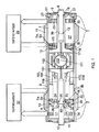
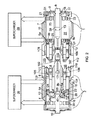
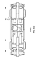
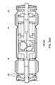
図1および2に示されたように、本発明のエンジン形態は、右シリンダ7、左シリンダ8およびそれらのシリンダの間に配置された単一の中央クランクシャフト112を具備している(明確化のために、1と2とを隔離するためのエンジンの多くの支持部材が図1および2から省略されている)。
右シリンダ7は個々に燃焼面23および25を有する外側ピストン3(PR0)および内側ピストン5(PR1)を備えており、それらの2つのピストンはその間に燃焼チャンバ27を形成している。左シリンダ8はそれと同様に、個々に燃焼面24および26を有する外側ピストン4(PL0)および内側ピストン6(PR1)を備えており、燃焼チャンバ28を形成している。2つの外側ピストン3および4はスコッチヨーク(scotch yoke)101によって互いに剛的に接続されている。2つの上内側半割ピストン5aおよび6aはスコッチヨーク103によって共に剛的に接続され、2つの下内側ピストン5bおよび6bはスコッチヨーク104によって共に剛的に接続されている。好適な実施形態において、アセンブリを組み立て可能にするために、2つの内側ピストン/スコッチヨーク/シリンダ軸を通って且つクランクシャフト軸に直交した割れ目を有する半割ピストンは、結果的に共に剛的に固定され、それと同時にピストンリングシールのグループ17および18を捕捉している。
As shown in FIGS. 1 and 2, the engine configuration of the present invention includes a
The
外側ピストン3/スコッチヨーク101/ピストン4のシステムは、5つの偏心器のうちの中間の偏心器115に歯止め102を介して取り付けられている。内側ピストン/スコッチヨーク/ピストンのシステムは、5つの偏心器のうちの一組の内側の偏心器114および116に歯止め105および106を介して取り付けられている。4つのピストン3,4,5(a+b),6(a+b)は個々に複数のピストンリング19,20,21および22と共に示され、燃焼面の後方に配置されている。エンジンの他の実施形態において、追加のピストンリングがさらにピストン本体または合致したシリンダ壁に沿って使用されて、ポートからクランクケース118へのガスの抜けを最小化していてもよい。好適な実施形態において、追加のピストンリングは外側ゾーン31および32において使用されている。
The outer piston 3 /
シリンダはスリーブバルブ7および8ならびにそれらの個々のベアリングキャップ110および109から成り、それらは個々にクランクシャフトから偏心器113および117によって駆動されている。スリーブバルブ7および8は各々排気ポート35,34および吸気ポート33(左手スリーブバルブ8の吸気ポートは図示略)を備えている。右手シリンダのスリーブバルブ7において、外側ピストン3は排気ポート33を開閉し、内側ピストン5(a+b)は吸気ポート35を開閉する。複数の径方向燃料噴射ポート37はピストンの管状アタッチメントを貫通し、噴射機9の径方向燃料噴射ノズル39からの燃料通路を提供しており、ポート37が噴射段階の際にノズル39を位置合わせして包む場合にノズル39が燃焼チャンバ27に接近する。それと同様に、左手のスリーブバルブ8において、外側ピストン4は排気ポート34を開閉し、内側ピストン6(a+b)は吸気ポート36を開閉する。複数の径方向燃料噴射ポート38はピストンの管状アタッチメントを貫通し、噴射機10の径方向燃料噴射ノズル40からの燃料通路を提供しており、ポート38が噴射段階の際にノズル40を位置合わせして包む場合にのみノズル40が燃焼チャンバ28に接近する(図1および2では左シリンダにおいて起こっている)。
The cylinder consists of
5つのクランクシャフト偏心器113,114,115,116および117の各々は、クランクシャフト回転軸111に対して独自に配置されている。図示された実施形態において、外側排気ピストン115に関する偏心器ならびに内側吸気ピストン114および115に関する同軸の偏心器は、クランクシャフト回転軸111から同じ径方向の距離である。好適な実施形態において、スコッチヨーク101は内側吸気ピストン5(a+b)および6(a+b)内に代替的に受容され、偏心器115の半径はこれによって制限されている。しかしながら、同軸の偏心器114および116にはそれに等しい制限は存在せず、したがって、これらの偏心器の半径を伸ばすことが可能であり、これは内側吸気ピストンのストロークの増加の効果をもたらす。以前の対向ピストン2ストロークエンジンは、文献によれば、クランクシャフトの回転で約110°の吸気期間および約130°の排気期間を有している。得ることのできる最大のポート面積は関連するピストンのストロークと共に線形に変化するので、余分な吸気ピストンストロークは吸気及び排気ポートの面積の均等性を復元するだろう。そのサイズおよび負荷にしたがって、これが与えられたエンジンの任意の実施形態に関して所望されているかどうかということは、個別的な場合に基づいたさらなるコンピュータ解析および最適化試験に依存するだろう。
Each of the five
外側排気ピストンに関する偏心器115は2つのシリンダ内で排気ポートを開閉し、好適な実施形態では角度的に4°進んでおり、一方で(対称のポートタイミングを備えたエンジンの実施形態において理論的に180°対向したピストンに関しては)内側吸気ピストンに関する同軸の偏心器114および116は2つのシリンダ内で吸気ポートを開閉し、角度的に4°遅れている。同軸の偏心器113および117はシリンダスリーブバルブ動作を駆動し、偏心器115の位置に対して角度的に(90+4)°遅れている(クランクシャフトの回転方向は矢印で図示されているように反時計回りであることを記しておく)。
An eccentric 115 for the outer exhaust piston opens and closes the exhaust port in the two cylinders, which in the preferred embodiment is angularly advanced by 4 °, while (theoretical in an embodiment of the engine with symmetrical port timing) The coaxial eccentrics 114 and 116 for the inner intake piston open and close the intake ports in the two cylinders and are angularly delayed by 4 °.
偏心器の独自の位置は、エンジンのバランスと、スーパーチャージおよび廃棄のブローダウンからのエネルギの回復に対するエンジンの操作との双方に寄与しており、それらは以下に議論されている。エンジンバランスはクランクシャフトのすべての無回転力が相殺することに帰着し、したがって、いかにも議論されているように、クランクシャフトのデザインを簡素化することを可能にする。対向ピストンの使用はシリンダあたりのより大きな掃気容積を達成し、その一方でクランクシャフトスロー(crankshaft throws)を減少し、これによってエンジン高さを低減している。入れ子になったスコッチヨークの形態は非常に短く小型のエンジンとすることを可能にしている一方で、ピストン/シリンダ界面を介した反力による摩擦損失を大きく低減している。 The unique location of the eccentrics contributes both to engine balance and engine operation for energy recovery from supercharge and waste blowdown, which are discussed below. Engine balance results in all crankshaft non-rotating forces canceling out, thus allowing the crankshaft design to be simplified, as is just discussed. The use of opposed pistons achieves a larger scavenging volume per cylinder while reducing crankshaft throws, thereby reducing engine height. The nested scotch yoke configuration allows a very short and small engine, while greatly reducing friction loss due to reaction forces through the piston / cylinder interface.
比較可能な能力を備えた、主流の技術による製品である直列4シリンダの4ストロークエンジンと比較して、本発明のエンジンは組み付け適正、摩擦損失の低減および振動除去において大幅な改良を与えている。対向ピストン対向シリンダエンジンの高さは、クランクシャフトの最大スイープと得ることのできる最小クラッチ直径とによって、およびフライホイールの要求によって初期的に決定される。対向ピストンデザインを伴って、クランクシャフトスローは同じシリンダ変位の約半分に切られてもよい。したがって、直列4シリンダ4ストロークエンジンの高さ450mmと比較して、高さは約200mmに低減することが可能である。図示されたように、口径46.6mmを有する本発明を具現化したエンジンは158m3のスイープ容積をもたらす。単一の中央クランクシャフトと入れ子になったスコッチヨークとの形態は独自に小型エンジンとすることを可能にし、約720mmの幅を持った試作デザインにおいては、自動車、商用車および軽飛行機等に組み込むことが可能な幅である。152×83.5mmの口径およびストロークを伴って、結果的に5.5リッターのスイープ容積となっている。スーパーチャージャとアクセサリーとを備えて約130kgの質量が期待される。より小さい型が大部分の大量生産アプリケーションのために必要とされるだろう。 Compared to the in-line 4-cylinder 4-stroke engine, which is a mainstream technology product with comparable capabilities, the engine of the present invention offers significant improvements in assembly, friction loss reduction and vibration removal. . The height of the opposed piston opposed cylinder engine is initially determined by the maximum crankshaft sweep and the minimum clutch diameter that can be obtained, and by flywheel requirements. With an opposed piston design, the crankshaft throw may be cut to about half of the same cylinder displacement. Therefore, the height can be reduced to about 200 mm as compared to the 450 mm height of the in-line 4-cylinder 4-stroke engine. As shown, an engine embodying the invention having a caliber of 46.6 mm provides a sweep volume of 158 m 3 . The single central crankshaft and nested scotch yoke configuration allows for a unique small engine, and the prototype design with a width of about 720mm is incorporated into cars, commercial vehicles and light aircraft. It is possible width. The result is a 5.5 liter sweep volume with a caliber and stroke of 152 × 83.5 mm. With a supercharger and accessories, a mass of about 130 kg is expected. Smaller molds will be needed for most mass production applications.
ピストン/シリンダ界面を介した反力による摩擦は本発明によって大幅に減少した。最先端技術による直列4シリンダ4ストロークエンジンはクランクシャフトスローを備え、約0.25の連結ロッド中心比(centres ratio)λである。スコッチヨーク機構のために、無限値λが達成され、ピすべてのストンの完全な単振動に帰結する。 Friction due to reaction forces through the piston / cylinder interface has been greatly reduced by the present invention. State-of-the-art in-line four-cylinder four-stroke engines have a crankshaft throw and a centres ratio λ of about 0.25. Due to the scotch yoke mechanism, an infinite value λ is achieved, resulting in a complete simple vibration of every stone.
本発明の2シリンダエンジンは、従来の直列4シリンダ4ストロークエンジンと全部で同じ数のピストンを備えているが、比較可能な出力に関しては、各々のピストンがより短い距離で往復するので、実際のピストン速度は大幅に低減されている。 The two-cylinder engine of the present invention has the same number of pistons in total as a conventional in-line four-cylinder four-stroke engine, but for comparable output, each piston reciprocates at a shorter distance, so The piston speed is greatly reduced.
外側ピストンからの引張が内側ピストンからの押圧に対向して作用するので、対向ピストンの形態は主軸受けの無回転燃焼力を大幅に相殺している。これらの大きい力はクランクシャフトに初期的に二面剪断の応力を負荷し、クランクシャフトにほぼ純粋なトルクを負わせる。したがって、主軸受けの数は2つに低減可能であり、クランクシャフトとエンジン支持構造とは対応してより軽量にされることが可能である。 Since the tension from the outer piston acts against the pressure from the inner piston, the configuration of the opposed piston greatly offsets the non-rotating combustion force of the main bearing. These large forces initially place a two-sided shear stress on the crankshaft, causing the crankshaft to bear a nearly pure torque. Therefore, the number of main bearings can be reduced to two, and the crankshaft and the engine support structure can be made correspondingly lighter.
本発明のエンジンは、以下に議論するように、排気及び吸気ポートタイミングにおいて大幅なひずみを伴っていても全体的に動力学的にバランスがとられている。このことは2つのピストン/スコッチヨーク/ピストンシステムの質量/偏心器スロー(mass/eccentric throw)の積の不均等な要素を確実に是正するスリーブバルブの質量/偏心スローの積の使用によって達成される。さらに、スリーブバルブの動作は排気および吸気ポートタイミングを改良して、ポートタイミングのひずみがクランクシャフト偏心器のひずみの少なくとも3倍とされることが可能である。 The engine of the present invention is generally kinetically balanced even with significant distortions in exhaust and intake port timing, as discussed below. This is achieved by the use of a sleeve valve mass / eccentric throw product that reliably corrects for unequal elements of the mass / eccentric throw product of the two piston / scotch yoke / piston systems. The In addition, sleeve valve operation can improve exhaust and intake port timing so that port timing distortion is at least three times greater than crankshaft eccentric distortion.
本発明のエンジン形態は過給に十分に適している。図1及び2に図示された好適な実施形態において、エンジンの各々のシリンダは別個の過給器29および30を備えている。2つのシリンダのみを伴って、過給器は、パルスターボチャージとしてそのような技術をより現実的にするために各々のシリンダに経済的に専用であってもよい。過給器は好適に電気モータ補助ターボチャージャであり。改良された掃気作用の働きがあり、低エンジン速度におけるエンジン特性を改良する一方で、ターボラグを回避し且つエンジンの排気(構成(compounding))からのエネルギ回収を行う。そのことは常温始動のために吸入空気を予熱することと同様に以下に記載されている。
The engine configuration of the present invention is well suited for supercharging. In the preferred embodiment illustrated in FIGS. 1 and 2, each cylinder of the engine is provided with a
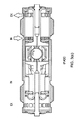
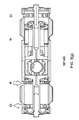
エンジン動作
図3はクランクシャフトの一回転にわたった本発明のエンジンの動作を示している。図3(a)〜3(m)は30°回転ごとのピストン位置、スリーブバルブならびに関連した排気及び吸気ポート位置を示している(図3のクランクシャフトの回転は矢印で示されたように反時計回りであることを記しておく)。クランクシャフト角度φは図番の右側に示されており、ADC(死点後)と付されている。それは、左右のピストンが同時にそれぞれIDC(内死点)およびODC(外死点)となるからである。吸気ポートINおよび排気ポートEXにおける矢印は、ポートが開いていることを示している。
Engine Operation FIG. 3 shows the operation of the engine of the present invention over one revolution of the crankshaft. 3 (a) -3 (m) show the piston position, sleeve valve and associated exhaust and intake port positions for every 30 ° rotation (rotation of the crankshaft in FIG. 3 is counterclockwise as indicated by the arrows). Note that it is clockwise.) The crankshaft angle φ is shown on the right side of the figure and is labeled ADC (after dead center). This is because the left and right pistons simultaneously become IDC (internal dead center) and ODC (external dead center), respectively. The arrows at the intake port IN and the exhaust port EX indicate that the ports are open.
ADC0°における図3(a)はクランクシャフト位置0°(左シリンダにおいてIDCとして独自に定義されている)におけるエンジンを示している。この位置において、左外側ピストンPL0および左内側ピストンPL1はそれらが最も接近した位置である。クランクシャフトの回転のこの角度近傍において、直接噴射型のエンジンでは、燃料供給は左シリンダ内に噴射され、燃焼が開始する。この位置において、左シリンダの排気及び吸気ポート(EXおよびIN)はそれぞれPL0およびPL1によって完全に閉じされている。排気ポートを作動するピストンのタイミングは4°進み、吸気ポートを作動するピストンのタイミングは4°遅れているので、PL0がちょうど方向を変えたときに、双方のピストンPL0とPL1とは左側に向かう僅かな速度を有する。右シリンダにおいて、右外側シリンダPR0と右内側シリンダPR1とは最も遠く離れた位置にある。右シリンダの排気ポートEXと吸気ポートINとの双方は矢印で示されたように開いており、先の燃焼サイクルによる排ガスは一方向に流れて取り除かれる(ループ流れよりもむしろ一方向流れ)。左シリンダ内のピストンのように、PR0およびPR1の双方は左側に向かう僅かな速度を有していなければならず、それは、PR0がちょうど方向を変えたときに、PR0とPR1とは入れ子のヨーク機構によって剛体的に連結されているためである。双方のスリーブバルブは一体になって動き、ピストンPL0とPR0との作動遅れは(90+4)°であり、ピストンPL1とPR1との作動進みは(90+4)°であり、双方のスリーブバルブは右に向かう最大速度を伴って中間ストロークに位置し、これによってポートタイミングに影響するような変化の原因とならない。
FIG. 3A at
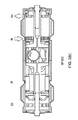
ADC30°の図3(b)において、左シリンダのPL0とPL1とは爆発工程の開始時において別々に動いており、PL1は移動の方向を変える。PL0はPL1よりも8°先行しているので、PL0はPL1よりも高速で移動している。右シリンダにおいて、ポートEXおよびINの双方のセットは矢印で示されたように開いたままであるが、ポートEXは閉じ始めている。双方のスリーブバルブはピストン中間ストローク位置の右への偏心器スロー(eccentrics' throw)の50%であって、右への移動途中であり、これによって右シリンダの吸気ポートINの開きを増加させ、排気ポートEXの開きを減少させる。
In FIG. 3B of
ADC60°の図3(c)において、左シリンダは爆発工程が継続しており、2つのピストンPL0とPL1とはより均等に近いが対向した速度となっている。右シリンダにおいて、外側ピストンPR0は排気ポートEXを閉じ、一方で吸気ポートINは部分的に開いたままで、矢印で示された過吸気を受け入れている。双方のスリーブバルブはピストン中間ストローク位置の右への偏心器スローの87%であって、右への移動途中であり、これによって右シリンダにおける吸気ポートINの開きを増加させ、排気ポートEXの閉鎖を加速している。 In FIG. 3 (c) at ADC 60 °, the explosion process is continued in the left cylinder, and the two pistons P L0 and P L1 are closer to each other but at the opposite speed. In the right cylinder, the outer piston PRO closes the exhaust port EX, while the intake port IN remains partially open and accepts over-intake indicated by the arrows. Both sleeve valves are 87% of the eccentric eccentric throw to the right of the piston intermediate stroke position and are moving to the right, thereby increasing the opening of the intake port IN in the right cylinder and closing the exhaust port EX Is accelerating.
ADC90°の図3(d)において、左シリンダは爆発工程が継続しており、一方で右シリンダにおいては、PR1は吸気ポートINを閉じ、2つのピストンPR0とPR1とは互いに向かって移動し、それらの間の空気を圧縮する。双方のスリーブバルブはピストン中間ストローク位置の右への偏心器スローの100%であり、静止しており、右シリンダにおける吸気ポートの閉鎖を遅らせている。 In FIG. 3 (d) at ADC 90 °, the left cylinder continues the explosion process, while in the right cylinder, P R1 closes the intake port IN and the two pistons P R0 and P R1 face each other. Move and compress the air between them. Both sleeve valves are 100% of the eccentric throw to the right of the piston intermediate stroke position and are stationary, delaying the closing of the intake port in the right cylinder.
ADC120°の図3(e)において、左シリンダのピストンPL0は矢印で示したように排気ポートEXを開き、一方で吸気ポートは閉じたままである。この“ブローダウン”状態において、燃焼チャンバから膨張するガスの運動エネルギは、次の充填燃料の圧縮および/または電気エネルギの発生のためのターボチャージャ(“パルス”ターボチャージ)によって外部から回収され得る。発生した電気エネルギはエンジンのクランクシャフト(構成(compounding))に貯蔵および/または供給されてもよい。双方のスリーブバルブはピストン中間ストローク位置の右への偏心器スローの87%であって、左へ移動しており、これによって左シリンダにおける排気ポートEXの開きを増加させ、吸気ポートINの開きを遅らせている。 In FIG. 3 (e) at ADC 120 °, the left cylinder piston P L0 opens the exhaust port EX as indicated by the arrow while the intake port remains closed. In this “blow-down” state, the kinetic energy of the gas expanding from the combustion chamber can be recovered externally by a turbocharger (“pulse” turbocharge) for subsequent filling fuel compression and / or generation of electrical energy. . The generated electrical energy may be stored and / or supplied to the engine crankshaft (compounding). Both sleeve valves are 87% of the eccentric throw to the right of the piston intermediate stroke position and are moving to the left, thereby increasing the opening of the exhaust port EX in the left cylinder and opening the intake port IN. Delayed.
ADC150°の図3(f)において、左シリンダのピストンPL0は吸気ポートINを開き、シリンダは矢印で図示されたように一方向流れで清掃される。右シリンダは圧縮ストロークの終端に近付き、“圧搾”段階が開始する。これはピストンPR0およびPR1の外側面、環状面および対向面がそれらの間から空気を放出し始める位置であり、それは破線の矢印によって図示されている。双方のスリーブバルブはピストン中間ストローク位置の右への偏心器スローの50%であって、左への移動途中であり、これによって左シリンダにおける排気ポートEXの開きを増加させ、吸気ポートINの開きを減少させる。 In FIG. 3 (f) at ADC 150 °, the piston P L0 of the left cylinder opens the intake port IN, and the cylinder is cleaned in a one-way flow as shown by the arrows. The right cylinder approaches the end of the compression stroke and the “squeezing” phase begins. This is the position at which the outer, annular and opposing surfaces of the pistons P R0 and P R1 begin to release air between them, which is illustrated by the dashed arrows. Both sleeve valves are 50% of the eccentric throw to the right of the piston intermediate stroke position and are moving to the left, thereby increasing the opening of the exhaust port EX in the left cylinder and opening of the intake port IN Decrease.
ADC180°の図3(g)において、左シリンダのピストンPL0およびPL1はEXおよびINの双方のポートを矢印で示したように開いたままにし、一方向流れの掃気を継続する。外側ピストンPL0は移動の方向を変える。右シリンダがIDC位置に到達し、そこはピストンPR0およびPR1はそれらの最も近接した位置であり、PR0はちょうど方向を変える。“圧搾”段階は破線の矢印で示されたように継続しており、“スモークリング(smoke ring)”効果を増大させて、部分的に正接の吸気ポートINに起因したすでに存在しているシリンダ軸周りの渦に併発させる。これらの構成ガスの動作は、燃焼チャンバが円錐曲線回転面に最も近く、最小の容積である場合に、IDCにおいて最も強烈になる。この位置において、複数の径方向スプレーが、点の領域で示されたように、中央燃料噴射機から放射され、得られる空気のほとんどすべてに到達し、構成(compounding)を備えた効果的な燃焼導入がそのクラスで最高の特別な燃費をもたらす。双方のスリーブバルブは左への最大速度となって中間ストロークに位置し、これによって変化の影響がポートタイミングに与えられない。 In FIG. 3 (g) at ADC 180 °, the left cylinder pistons P L0 and P L1 keep both ports EX and IN open as indicated by the arrows, and continue scavenging for one-way flow. The outer piston P L0 changes the direction of movement. The right cylinder reaches the IDC position, where pistons P R0 and P R1 are their closest positions, and P R0 just changes direction. The “squeezing” phase continues as indicated by the dashed arrows, increasing the “smoke ring” effect and partially existing cylinders due to the tangential intake port IN Co-occurs in a vortex around the axis. The operation of these constituent gases is most intense in the IDC when the combustion chamber is closest to the conic rotation plane and has the smallest volume. In this position, multiple radial sprays radiate from the central fuel injector and reach almost all of the resulting air, as shown in the area of the dots, and effective combustion with compounding Introducing the best special fuel economy in its class. Both sleeve valves have a maximum speed to the left and are located in the middle stroke, so that the change is not affected by the port timing.
ADC210°の図3(h)において、左シリンダでは、ポートEXおよびINのセットの双方は矢印で示されたように開いたままであるが、ポートEXは閉じ始めている。右シリンダのピストンPR0およびPR1は爆発工程の開始時において別々に動いており、PR1は移動の方向を変える。PR0はPR1よりも8°先行しているので、PR0はPR1よりも高速で移動している。双方のスリーブバルブはピストン中間ストローク位置の左への偏心器スローの50%であって、左への移動途中であり、これによって左シリンダの吸気ポートINの開きを増加させ、排気ポートEXの開きを減少させる。 In FIG. 3 (h) at ADC 210 °, in the left cylinder, both sets of ports EX and IN remain open as indicated by the arrows, but port EX begins to close. The piston P R0 and P R1 of the right cylinder are moved apart at the beginning of the power stroke, P R1 is changing the direction of movement. Since P R0 are 8 ° ahead P R1, P R0 is moving faster than P R1. Both sleeve valves are 50% of the eccentric throw to the left of the piston intermediate stroke position and are moving to the left, thereby increasing the opening of the intake port IN of the left cylinder and opening of the exhaust port EX Decrease.
ADC240°の図3(i)において、左シリンダでは、外側ピストンPL0は排気ポートEXを閉じ、一方で吸気ポートINは部分的に開いたままで、矢印で示されたように過吸気を受容する。右シリンダはその爆発工程を継続しており、2つのピストンPR0とPR1とはより均等に近いが対向した速度となっている。双方のスリーブバルブはピストン中間ストローク位置の左への偏心器スローの87%であって、左への移動途中であり、これによって左シリンダにおける吸気ポートINの開きを増加させ、排気ポートEXの閉鎖を加速している。 In FIG. 3 (i) at ADC 240 °, in the left cylinder, the outer piston P L0 closes the exhaust port EX, while the intake port IN remains partially open and receives over-intake as indicated by the arrows. . Right cylinder has continued its power stroke, is close more evenly the two pistons P R0 and P R1 has a face speed. Both sleeve valves are 87% of the eccentric stroke to the left of the piston intermediate stroke position and are moving to the left, thereby increasing the opening of the intake port IN in the left cylinder and closing the exhaust port EX Is accelerating.
ADC270°の図3(j)において、左シリンダでは、PL1は吸気ポートINを閉じ、2つのピストンPL0とPL1とは互いに向かって移動し、それらの間の空気を圧縮する。一方で右シリンダは爆発工程を継続している。双方のスリーブバルブはピストン中間ストローク位置の左への偏心器スローの100%であり、静止しており、左シリンダにおける吸気ポートの閉鎖を遅らせている。 In FIG. 3 (j) at ADC 270 °, in the left cylinder, P L1 closes the intake port IN and the two pistons P L0 and P L1 move toward each other, compressing the air between them. On the other hand, the right cylinder continues the explosion process. Both sleeve valves are 100% of the eccentric throw to the left of the piston intermediate stroke position and are stationary, delaying the closing of the intake port in the left cylinder.
ADC300°の図3(k)において、左シリンダでは、ピストンPL0とPL1とは圧縮ストロークを継続している。右シリンダのピストンPR0は矢印で示されたように排気ポートEXを開き、一方で吸気ポートINは閉じたままである。この“ブローダウン”状態において、燃焼チャンバから膨張するガスの運動エネルギは、次の充填燃料の圧縮および/または電気エネルギの発生のためのターボチャージャ(“パルス”ターボチャージ)によって外部から回収され得る。発生した電気エネルギはエンジンのクランクシャフト(構成(compounding))に貯蔵および/または供給されてもよい。双方のスリーブバルブはピストン中間ストローク位置の左への偏心器スローの87%であって、右へ移動しており、これによって右シリンダにおける排気ポートEXの開きを増加させ、吸気ポートINの開きを遅らせている。 In FIG. 3 (k) at ADC 300 °, in the left cylinder, the pistons P L0 and P L1 continue the compression stroke. The right cylinder piston P R0 opens the exhaust port EX as indicated by the arrow, while the intake port IN remains closed. In this “blow-down” state, the kinetic energy of the gas expanding from the combustion chamber can be recovered externally by a turbocharger (“pulse” turbocharge) for subsequent filling fuel compression and / or generation of electrical energy. . The generated electrical energy may be stored and / or supplied to the engine crankshaft (compounding). Both sleeve valves are 87% of the eccentric throw to the left of the piston intermediate stroke position and are moving to the right, thereby increasing the opening of the exhaust port EX in the right cylinder and opening the intake port IN. Delayed.
ADC330°の図3(l)において、左シリンダは圧縮ストロークの終端に近付き、“圧搾”段階が開始する。これはピストンPL0およびPL1の外側面、環状面および対向面がそれらの間から空気を放出し始める位置であり、それは破線の矢印によって図示されている。右シリンダのピストンPR0は吸気ポートINを開き、シリンダは矢印で図示されたように一方向流れで清掃される。双方のスリーブバルブはピストン中間ストローク位置の左への偏心器スローの50%であって、右への移動途中であり、これによって右シリンダにおける排気ポートEXの開きを増加させ、吸気ポートINの開きを減少させる。 In FIG. 3 (l) at ADC 330 °, the left cylinder approaches the end of the compression stroke and the “squeeze” phase begins. This is the position at which the outer, annular and opposing surfaces of the pistons P L0 and P L1 begin to release air between them, which is illustrated by the dashed arrows. The right cylinder piston PRO opens the intake port IN and the cylinder is cleaned in one direction as shown by the arrows. Both sleeve valves are 50% of the eccentric throw to the left of the piston intermediate stroke position and are moving to the right, thereby increasing the opening of the exhaust port EX in the right cylinder and the opening of the intake port IN Decrease.
ADC360°の図3(m)において、位置は図3(a)に示されたものと同一である。左シリンダはIDC位置に到達し、そこでピストンPL0およびPL1はそれらの最も近接した位置であり、PL0は方向を変える。“圧搾”段階は破線の矢印で示されたように継続しており、“スモークリング(smoke ring)”効果を増大させて、部分的に正接の吸気ポートINに起因したすでに存在しているシリンダ軸周りの渦に併発させる。これらの構成ガスの動作は、燃焼チャンバが円錐曲線回転面に最も近く、最小の容積である場合に、IDCにおいて最も強烈になる。この位置において、複数の径方向スプレーが、点の領域で示されたように、中央燃料噴射機から放射され、得られる空気のほとんどすべてに到達し、構成(compounding)を備えた効果的な燃焼導入がそのクラスで最高の特別な燃費をもたらす。右シリンダのピストンPR0およびPR1はEXおよびINの双方のポートを開いたままにし、矢印で示したように一方向流れの掃気を継続する。外側ピストンPR0は移動の方向を変える。双方のスリーブバルブは左への最大速度となって中間ストロークに位置し、これによって変化の影響がポートタイミングに与えられない。 In FIG. 3 (m) of the ADC 360 °, the position is the same as that shown in FIG. 3 (a). The left cylinder reaches the IDC position, where pistons P L0 and P L1 are their closest positions, and P L0 changes direction. The “squeezing” phase continues as indicated by the dashed arrows, increasing the “smoke ring” effect and partially existing cylinders due to the tangential intake port IN Co-occurs in a vortex around the axis. The operation of these constituent gases is most intense in the IDC when the combustion chamber is closest to the conic rotation plane and has the smallest volume. In this position, multiple radial sprays radiate from the central fuel injector and reach almost all of the resulting air, as shown in the area of the dots, and effective combustion with compounding Introducing the best special fuel economy in its class. The right cylinder pistons P R0 and P R1 leave both the EX and IN ports open and continue scavenging in one direction as indicated by the arrows. The outer piston P R0 changes the direction of movement. Both sleeve valves have a maximum speed to the left and are located in the middle stroke, so that the change is not affected by the port timing.
特定の角度およびタイミングはクランクシャフトの幾何形状およびポートサイズとその位置とに依存する。これまでの記載は単に本発明の概念を示すことを意図している。 The particular angle and timing depends on the crankshaft geometry and port size and its position. The above description is merely intended to illustrate the concept of the present invention.
排気および吸気ポートの非対称タイミング
2ストロークエンジンにおける排気および吸気ポートの非対称タイミングは、大河の重要な利点をもたらす。排気ポートが吸気ポートよりも前に開いた場合、排ガス内のエネルギはターボチャージャによってより効果的に回収されることが可能であり、排気ポートが吸気ポートよりも前に閉じた場合、シリンダはより効果的に過給され得る。
Exhaust and intake port asymmetric timing Exhaust and intake port asymmetric timing in a two-stroke engine provides significant advantages for large rivers. If the exhaust port opens before the intake port, the energy in the exhaust gas can be recovered more effectively by the turbocharger, and if the exhaust port closes before the intake port, the cylinder is more It can be supercharged effectively.
本発明のエンジン形態において、上述の通り、排気ポートは各々のシリンダ内の外側ピストンによって制御され、吸気ポートは内側ピストンによって制御される。この形態は効果的な掃気(“一方向流れ”の掃気)を可能にするだけでなく、排気および吸気ポートの単独の非対称タイミングを可能にしている。 In the engine configuration of the present invention, as described above, the exhaust port is controlled by the outer piston in each cylinder, and the intake port is controlled by the inner piston. This configuration not only allows for effective scavenging (“one-way flow” scavenging), but also allows for independent asymmetric timing of the exhaust and intake ports.
各々のシリンダ内の2つのピストンの非対称タイミングは、クランクシャフトジャーナルに対応した相対角度位置の変化によって達成される。180°離れた排気および吸気ピストンに関するジャーナルの位置決めは、双方のピストンが同時に(対称のタイミングで)最大および最小偏位に到達することに帰着する。本発明の好適な実施形態において、排気ピストンのためのジャーナルは角度的に4°進んでおり、吸気ポートのためのジャーナルは4°遅れている(これによって内側および外側の死点は、対称タイミングのエンジンの場合と同一のクランクシャフト角度となるが、双方のピストンはシリンダに対して小さい共通速度(small common velocity)を有している)。それに加えて、これは双方のスリーブバルブの共通速度の寄与であり、その寄与はすべての排気および吸気ポートならびにそれらの動作が90°だけ排気ピストンの内死点を遅らせることを含んでいる。好適な実施形態におけるこの動作は効果的に排気ピストンを12.5°進むまで且つ効果的に吸気ピストンを12.5°遅れるまで増加させる。結果的に、排気ポートは“ブローダウン”のために吸気ポートよりも前に開き、過給のために吸気ポートよりも後に閉じる。 Asymmetric timing of the two pistons in each cylinder is achieved by a change in relative angular position corresponding to the crankshaft journal. The positioning of the journal with respect to the exhaust and intake pistons 180 ° apart results in both pistons reaching maximum and minimum excursions simultaneously (with symmetrical timing). In the preferred embodiment of the present invention, the journal for the exhaust piston is angularly advanced by 4 ° and the journal for the intake port is delayed by 4 ° (this ensures that the inner and outer dead centers are symmetrical timing). The same crankshaft angle as in the case of the engine, but both pistons have a small common velocity relative to the cylinder). In addition, this is a common speed contribution of both sleeve valves, which includes all exhaust and intake ports and their action delaying the exhaust piston's internal dead center by 90 °. This action in the preferred embodiment effectively increases the exhaust piston by 12.5 ° and effectively increases the intake piston by 12.5 °. As a result, the exhaust port opens before the intake port for “blow down” and closes after the intake port for supercharging.
スリーブバルブの質量/偏心器スローの積は、ピストンジャーナルの非対称に起因した初期不釣合いを完全に排除するように適合され得る。したがって本発明は2シリンダストロークエンジンについて開示しており、そのエンジンは初期およびすべてのより高いオーダーにおいて完全なバランスを達成し得る。さらに、対向ピストン/スコッチヨーク/ピストンシステムのマス/偏心器スロー製品が均等なままである限り、排気および吸気ピストンのストロークは異なっていてもよく、そのことは最良の性能のための得られる最大ポート面積の最適化を可能にする。
The mass of the sleeve valve / eccentric throw may be adapted to completely eliminate the initial imbalance due to piston journal asymmetry. The present invention thus discloses a two cylinder stroke engine, which can achieve perfect balance in the initial and all higher orders. Further, as long as the mass / eccentric throw product of the opposed piston / scotch yoke / piston system remains uniform, the strokes of the exhaust and intake pistons may be different, which is the maximum obtained for best performance Allows optimization of port area.
対向ピストン対向シリンダ形態の大型エンジンへの適応性
多くのエンジン形態において、バランスは4,6,8またはそれ以上のシリンダを備えることに依存しており、シリンダは個々のピストンによって導かれる自由マスフォース(free-mass forces)を打ち消すように配置されている。対向回転ウェイト(Counter-rotating weights)もしばしば取り入れられ、それが複雑さを加えて、エンジンの質量および摩擦損失となる。本発明の利点は、複数シリンダエンジンが複数の2シリンダエンジンを並べて配置し、それらのクランクシャフトを全体的に連結することによって形成されてもよいことである。連結は、オペレータまたはロジック制御の下のクラッチとしての手段等によって行ってもよく、低負荷時に必要とされない場合はシリンダの組が切り離されることが可能であってもよい。現実にあるエンジンは、部分的な負荷で稼動しているがシリンダがクランクシャフトに接続されたままであり且つピストンがシリンダ内で移動し続けており、したがってエンジンの寄生性の摩擦負荷が継続している場合に、全シリンダ数未満で使用される
Applicability to large engines with opposed piston opposed cylinder configuration In many engine configurations, the balance relies on having 4, 6, 8 or more cylinders, with the cylinders being free mass forces guided by individual pistons. It is arranged to counteract (free-mass forces). Counter-rotating weights are often also incorporated, which adds complexity and engine mass and friction losses. An advantage of the present invention is that a multi-cylinder engine may be formed by arranging a plurality of two-cylinder engines side by side and connecting their crankshafts as a whole. The coupling may be done by means such as an operator or a clutch under logic control, etc., and the set of cylinders may be able to be disconnected if not required at low loads. A real engine is running at a partial load, but the cylinder remains connected to the crankshaft and the piston continues to move within the cylinder, so the engine's parasitic friction load continues. Is used with less than the total number of cylinders
結論
上記の事項は本発明の特別な実施形態の詳細な記載である。開示された実施形態からの逸脱は本発明の範囲内であってもよく、明確な変更が当業者には考え付くだろう。本明細書は、発明が表題を付けられた保護の範囲に、過度に狭く解釈されるべきではない。
Conclusion The above is a detailed description of particular embodiments of the invention. Deviations from the disclosed embodiments may be within the scope of the invention, and obvious modifications will occur to those skilled in the art. This specification should not be construed to be unduly narrow in the scope of protection to which the invention is entitled.
以下の請求項中の対応する構造、材料、動作およびすべての手段またはステップと機能要素とは、他の請求項の要素と結合して機能を発揮するための任意の構造または動作を含むことを意図しており、それらは明確に主張されている。 Corresponding structures, materials, operations and all means or steps and functional elements in the following claims include any structure or operation for performing a function in combination with other claim elements. It is intended and they are clearly claimed.
3,4 ・・・外側ピストン
5,6 ・・・内側ピストン
7 ・・・右シリンダ
8 ・・・左シリンダ
9,10 ・・・噴射機
19,20,21,22 ・・・ピストンリング
23,24,25,26 ・・・燃焼面
27,28 ・・・燃焼チャンバ
29,30 ・・・スーパーチャージャ
31,32 ・・・外側ゾーン
33 ・・・吸気ポート
34,35 ・・・排気ポート
37,38 ・・・燃焼チャンバ
39,40 ・・・燃料噴射ノズル
101,103,104 ・・・スコッチヨーク
102,105,106 ・・・歯止め
111 ・・・クランクシャフト回転軸
112 ・・・中央クランクシャフト
113,117 ・・・偏心器
114,116 ・・・内側の偏心器
115 ・・・中間の偏心器
118 ・・・クランクケース
3, 4 ... outer pistons 5, 6 ...
Claims (30)
非対称に配置されたジャーナルと、該ジャーナルを前記ピストンから駆動するためのスコッチヨーク機構と、を備えたクランクシャフトを具備し、
前記各々のシリンダの前記ピストンは1つまたは複数の前記排気ポートを1つまたは複数の前記吸気ポートが開く前に開き、1つまたは複数の前記排気ポートを1つまたは複数の前記吸気ポートが閉じる前に閉じることを特徴とする2ストローク内燃エンジン。 Two opposing cylinders, each cylinder containing two pistons and having at least one exhaust port and at least one intake port;
A crankshaft comprising an asymmetrically disposed journal and a scotch yoke mechanism for driving the journal from the piston;
The piston of each cylinder opens one or more of the exhaust ports before the one or more intake ports are opened, and closes one or more of the exhaust ports with one or more of the intake ports. A two-stroke internal combustion engine characterized by closing forward.
クランクシャフトに隣接した内側端を備えた対向した2つのシリンダであって、各々の該シリンダは往復運動するように配置された内側および外側ピストンを備え、該シリンダの間に燃焼チャンバを形成しているシリンダと、
前記内側ピストンに剛的に取り付けられた第1および第2のスコッチヨーク機構であって、該機構は前記内側ピストンを一致して推進可能にクランクシャフトの対応したジャーナルに連結しているスコッチヨークと、
前記外側ピストンに剛的に取り付けられた第3のスコッチヨーク機構であって、該機構は前記外側ピストンを推進可能に前記クランクシャフトの対応したジャーナルに連結しているスコッチヨークと、
を具備していることを特徴とする2ストローク内燃エンジン。 A crankshaft with multiple journals;
Two opposed cylinders with an inner end adjacent to the crankshaft, each cylinder having inner and outer pistons arranged to reciprocate, forming a combustion chamber between the cylinders A cylinder,
First and second scotch yoke mechanisms rigidly attached to the inner piston, the mechanisms connecting the inner piston to a corresponding journal of a crankshaft for propulsion in unison; and ,
A third scotch yoke mechanism rigidly attached to the outer piston, the mechanism connecting the outer piston to a corresponding journal of the crankshaft for propulsion;
A two-stroke internal combustion engine comprising:
双方の前記シリンダは前記クランクシャフトから最も遠い外側端に前記排気ポートを備え、前記クランクシャフトに最も近い内側端に前記吸気ポートを備えていることを特徴とする請求項11〜17のいずれか一項に記載のエンジン。
18. The cylinder according to claim 11, wherein both of the cylinders are provided with the exhaust port at an outer end farthest from the crankshaft, and the intake port at an inner end closest to the crankshaft. The engine according to item.
各々の該シリンダは2つの対向したピストンを収容し、1つ以上の吸気ポートと1つ以上の排気ポートと、前記ピストンを駆動するためのクランクシャフトを備え、
各々の前記シリンダは、前記クランクシャフトによって駆動されて少なくとも1つの前記吸気および排気ポートの開閉を制御するスリーブバルブを具備していることを特徴とする2ストローク内燃エンジン。 Including two opposed cylinders,
Each of the cylinders accommodates two opposed pistons and includes one or more intake ports, one or more exhaust ports, and a crankshaft for driving the pistons;
Each of the cylinders includes a sleeve valve that is driven by the crankshaft to control opening and closing of at least one of the intake and exhaust ports.
各々の該シリンダは2つの対向したピストンを収容し、1つ以上の吸気ポートと1つ以上の排気ポートと、非対称に配置されたジャーナルを備えたクランクシャフトを備え、前記クランクシャフトは前記ピストンから前記ジャーナルを駆動するためのものであり、
各々の前記シリンダは、前記クランクシャフトによって駆動されて少なくとも1つの前記吸気および排気ポートの開閉を制御するスリーブバルブを具備していることを特徴とする2ストローク内燃エンジン。 Including two opposed cylinders,
Each cylinder contains two opposed pistons and includes a crankshaft with one or more intake ports, one or more exhaust ports, and an asymmetrically disposed journal, the crankshafts extending from the pistons. For driving the journal,
Each of the cylinders includes a sleeve valve that is driven by the crankshaft to control opening and closing of at least one of the intake and exhaust ports.
前記クランクシャフトに最も近い内側端を備えた2つの対向したシリンダであって、各々の前記シリンダはそれらのシリンダ内に配置された内側および外側ピストンを備え、それらのシリンダの間に燃焼チャンバを形成したシリンダと、を含み、
各々の前記ピストンは個々の管状部材によって前記クランクシャフトに推進可能に連結されており、前記管状部材は全体的に前記燃焼チャンバを通る軸方向に延在し、前記管状部材に収容された燃料噴射手段は前記燃焼チャンバ内に径方向外側に燃料を噴射するように配置されていることを特徴とする2ストローク内燃エンジン。 A crankshaft,
Two opposed cylinders with inner ends closest to the crankshaft, each said cylinder comprising inner and outer pistons disposed in those cylinders, forming a combustion chamber between the cylinders A cylinder, and
Each piston is propellably connected to the crankshaft by an individual tubular member, the tubular member extending generally axially through the combustion chamber, and a fuel injection contained in the tubular member A two-stroke internal combustion engine characterized in that the means is arranged to inject fuel radially outward into the combustion chamber.
前記クランクシャフトに隣接した内側端を備えた2つの対向したシリンダであって、各々の前記シリンダはそれらのシリンダ内に配置された内側および外側ピストンを備え、それらのシリンダの間に燃焼チャンバを形成したシリンダと、
前記内側ピストンに剛的に取り付けられた第1および第2のスコッチヨーク機構であって、一致して作動し、前記内側ピストンを前記クランクシャフトの対応した前記ジャーナルに推進可能に連結している第1および第2のスコッチヨーク機構と、
前記外側ピストンに剛的に取り付けられた第3のスコッチヨーク機構であって、前記外側ピストンを前記クランクシャフトの対応した前記ジャーナルに推進可能に連結している第3のスコッチヨーク機構と、
を含んでいることを特徴とする2ストローク内燃エンジン。 A crankshaft with multiple journals;
Two opposing cylinders with an inner end adjacent to the crankshaft, each said cylinder having inner and outer pistons disposed within those cylinders, forming a combustion chamber between the cylinders Cylinder
First and second scotch yoke mechanisms rigidly attached to the inner piston, wherein the first and second scotch yoke mechanisms operate in unison and are propulsively coupled to the corresponding journal of the crankshaft. First and second scotch yoke mechanisms;
A third scotch yoke mechanism rigidly attached to the outer piston, the third scotch yoke mechanism drivingly connecting the outer piston to the corresponding journal of the crankshaft;
A two-stroke internal combustion engine comprising:
Applications Claiming Priority (2)
| Application Number | Priority Date | Filing Date | Title |
|---|---|---|---|
| GBGB0710852.5A GB0710852D0 (en) | 2007-06-06 | 2007-06-06 | Internal combustion engines |
| PCT/GB2008/001798 WO2008149061A2 (en) | 2007-06-06 | 2008-05-28 | Internal combustion engines |
Related Child Applications (2)
| Application Number | Title | Priority Date | Filing Date |
|---|---|---|---|
| JP2012100894A Division JP5662374B2 (en) | 2007-06-06 | 2012-04-26 | Internal combustion engine |
| JP2012100895A Division JP5690772B2 (en) | 2007-06-06 | 2012-04-26 | Internal combustion engine |
Publications (1)
| Publication Number | Publication Date |
|---|---|
| JP2010529353A true JP2010529353A (en) | 2010-08-26 |
Family
ID=38318828
Family Applications (3)
| Application Number | Title | Priority Date | Filing Date |
|---|---|---|---|
| JP2010510866A Pending JP2010529353A (en) | 2007-06-06 | 2008-05-28 | Internal combustion engine |
| JP2012100895A Expired - Fee Related JP5690772B2 (en) | 2007-06-06 | 2012-04-26 | Internal combustion engine |
| JP2012100894A Expired - Fee Related JP5662374B2 (en) | 2007-06-06 | 2012-04-26 | Internal combustion engine |
Family Applications After (2)
| Application Number | Title | Priority Date | Filing Date |
|---|---|---|---|
| JP2012100895A Expired - Fee Related JP5690772B2 (en) | 2007-06-06 | 2012-04-26 | Internal combustion engine |
| JP2012100894A Expired - Fee Related JP5662374B2 (en) | 2007-06-06 | 2012-04-26 | Internal combustion engine |
Country Status (16)
| Country | Link |
|---|---|
| US (1) | US8499726B2 (en) |
| EP (2) | EP2171211B1 (en) |
| JP (3) | JP2010529353A (en) |
| KR (3) | KR101458247B1 (en) |
| CN (2) | CN103511079B (en) |
| CY (1) | CY1117121T1 (en) |
| DK (1) | DK2171211T3 (en) |
| ES (1) | ES2556945T3 (en) |
| GB (3) | GB0710852D0 (en) |
| HK (1) | HK1175826A1 (en) |
| HR (1) | HRP20160070T1 (en) |
| HU (1) | HUE026639T2 (en) |
| IL (1) | IL202491A (en) |
| PT (1) | PT2171211E (en) |
| SI (1) | SI2171211T1 (en) |
| WO (1) | WO2008149061A2 (en) |
Cited By (2)
| Publication number | Priority date | Publication date | Assignee | Title |
|---|---|---|---|---|
| JP2014515453A (en) * | 2011-05-24 | 2014-06-30 | コックス パワートレイン リミテッド | Internal combustion engine |
| JP2014515454A (en) * | 2011-05-24 | 2014-06-30 | コックス パワートレイン リミテッド | Internal combustion engine |
Families Citing this family (25)
| Publication number | Priority date | Publication date | Assignee | Title |
|---|---|---|---|---|
| GB2477272B (en) | 2010-01-27 | 2014-06-25 | Two Stroke Developments Ltd | Internal combustion engine comprising piston dwell mechanism |
| DE102010038543A1 (en) * | 2010-07-28 | 2012-02-02 | Robert Bosch Gmbh | About a steam power process drivable piston engine |
| US8763583B2 (en) * | 2011-02-11 | 2014-07-01 | Ecomotors, Inc. | Opposed-piston, opposed-cylinder engine with collinear cylinders |
| GB2493061A (en) * | 2011-07-15 | 2013-01-23 | Ecomotors Internat Inc | Opposed piston engine with toroidal combustion chamber |
| GB2495827A (en) * | 2011-10-20 | 2013-04-24 | Ecomotors Internat Inc | Balancing an Opposed-Piston, Opposed-Cylinder Engine |
| GB201122432D0 (en) | 2011-12-23 | 2012-02-08 | Cox Powertrain Ltd | Internal combustion engines |
| US8925528B2 (en) * | 2012-06-26 | 2015-01-06 | Ford Global Technologies, Llc | Engine balancing supercharger |
| JP2016519736A (en) * | 2013-03-15 | 2016-07-07 | プライム グループ アライアンス, リミテッド ライアビリティ カンパニーPrime Group Alliance, LLC | Opposed piston internal combustion engine with non-viscous layer sealing |
| DE102013106755A1 (en) | 2013-06-27 | 2014-12-31 | Bertwin R. Geist | Sliding block for a crank-type reciprocating engine |
| CN103670698A (en) * | 2013-09-09 | 2014-03-26 | 安徽中鼎动力有限公司 | Engine body |
| WO2015056015A1 (en) * | 2013-10-17 | 2015-04-23 | Cox Powertrain Ltd | Internal combustion engines |
| US9032927B1 (en) * | 2013-11-08 | 2015-05-19 | Achates Power, Inc. | Cold-start strategies for opposed-piston engines |
| CN104564331A (en) * | 2015-01-28 | 2015-04-29 | 邵金彪 | Reciprocating-type synchronous stroke internal combustion engine with pistons in series connection |
| US9447754B1 (en) | 2015-07-02 | 2016-09-20 | Bright Acceleration Technologies LLC | Method and apparatus for internal combustion engine system with improved turbocharging |
| CN105804869A (en) * | 2016-03-15 | 2016-07-27 | 刘运金 | Double-shaft piston engine |
| US10082099B2 (en) * | 2016-08-09 | 2018-09-25 | Achates Power, Inc. | Port edge shape with continuous curvature for improved ring-port interaction and flow area |
| US10215129B2 (en) * | 2016-08-09 | 2019-02-26 | Achates Power, Inc. | Port edge shape with continuous curvature for improved ring-port interaction and flow area |
| US10364739B2 (en) | 2016-09-01 | 2019-07-30 | Bright Acceleration Technologies LLC | Synergistic induction and turbocharging in internal combustion engine systems |
| US10697357B2 (en) | 2016-09-01 | 2020-06-30 | Bright Acceleration Technologies LLC | Cross-port air flow to reduce pumping losses |
| US10107215B2 (en) | 2016-09-01 | 2018-10-23 | Bright Acceleration Technologies LLC | Synergistic induction and turbocharging in internal combustion engine systems |
| US9638095B1 (en) | 2016-09-01 | 2017-05-02 | Bright Acceleration Technologies LLC | Synergistic induction and turbocharging in internal combustion engine systems |
| CN106523131B (en) * | 2016-11-10 | 2018-12-18 | 宁波市鄞州煜隆工具有限公司 | A kind of two-stroke internal combustion engine |
| CN110621856B (en) * | 2017-03-13 | 2022-03-11 | 增强能源效率企业有限公司 | Internal combustion engine |
| GB201719042D0 (en) * | 2017-11-17 | 2018-01-03 | Oxford Two Stroke Ltd | Internal combustion engine |
| CN110185539B (en) * | 2019-07-01 | 2024-03-01 | 西北农林科技大学 | Double-cylinder internal combustion engine |
Family Cites Families (21)
| Publication number | Priority date | Publication date | Assignee | Title |
|---|---|---|---|---|
| US1257104A (en) * | 1916-05-26 | 1918-02-19 | Oscar A Olson | Internal-combustion engine. |
| US2093433A (en) | 1933-06-09 | 1937-09-21 | Greene Catharine De Motte | Internal combustion engine |
| US2132802A (en) * | 1937-07-21 | 1938-10-11 | Jefferson F Pierce | Internal combustion engine |
| US2169807A (en) * | 1938-03-04 | 1939-08-15 | George R Lyon | Compressor |
| US2213817A (en) * | 1939-04-03 | 1940-09-03 | Walter T Kinslow | Internal expansion engine |
| GB690479A (en) | 1947-12-19 | 1953-04-22 | Frederick Charles Hammick | Improvements in or relating to internal combustion engines having two pistons acted upon by the same impulse |
| DE2744686A1 (en) * | 1977-09-30 | 1979-04-05 | Hermann Prof Dipl Ing Schott | Opposed cylinder IC engine - has outer pistons of each pair linked by connecting rods outside cylinders |
| AU4236593A (en) * | 1992-05-06 | 1993-11-29 | Balanced Engines, Inc. | Balanced compound engine |
| DE19503442C1 (en) * | 1995-02-03 | 1996-05-23 | Daimler Benz Ag | Two=stroke opposed=piston engine |
| DE19503443C1 (en) | 1995-02-03 | 1996-05-15 | Daimler Benz Ag | Opposed piston two=stroke engine |
| JP3698858B2 (en) | 1997-06-10 | 2005-09-21 | リンナイ株式会社 | Gas shut-off valve |
| US6170443B1 (en) * | 1998-09-11 | 2001-01-09 | Edward Mayer Halimi | Internal combustion engine with a single crankshaft and having opposed cylinders with opposed pistons |
| US6065440A (en) * | 1999-07-07 | 2000-05-23 | Pasquan; Raymond F. | Internal combustion engine with binary cylinder sizing for variable power output |
| JP2001355451A (en) * | 2000-06-14 | 2001-12-26 | Walbro Japan Inc | Stratified scavenging two-stroke internal combustion engine |
| UA61980C2 (en) * | 2000-06-15 | 2003-12-15 | Ihor Olehovych Kyryliuk | Opposite internal combustion engine |
| US6536399B2 (en) * | 2000-11-15 | 2003-03-25 | Honda Giken Kogyo Kabushiki Kaisha | Crankshaft supporting structure for horizontal opposed type internal combustion engine |
| BG105831A (en) | 2001-08-20 | 2003-02-28 | Стоян КОКУДЕВ | Combined piston engine |
| US7004120B2 (en) * | 2003-05-09 | 2006-02-28 | Warren James C | Opposed piston engine |
| JP2006002803A (en) | 2004-06-15 | 2006-01-05 | Toyo Tire & Rubber Co Ltd | Suspension support |
| FR2888907A1 (en) * | 2005-07-21 | 2007-01-26 | Marie Therese Mazille | Crankshaft`s rotational movement transforming device for e.g. two stroke engine, has pistons displaced in cylinder comprising air inlet and exhaust ports, where height of ports is less than thickness of segments of pistons |
| GB2432398B (en) | 2005-11-18 | 2008-08-13 | Lotus Car | Reciprocating piston sleeve valve engine |
-
2007
- 2007-06-06 GB GBGB0710852.5A patent/GB0710852D0/en not_active Ceased
-
2008
- 2008-05-28 JP JP2010510866A patent/JP2010529353A/en active Pending
- 2008-05-28 ES ES08750704.2T patent/ES2556945T3/en active Active
- 2008-05-28 GB GB1215622.0A patent/GB2491297B/en not_active Expired - Fee Related
- 2008-05-28 GB GB0922628.3A patent/GB2463204B/en not_active Expired - Fee Related
- 2008-05-28 WO PCT/GB2008/001798 patent/WO2008149061A2/en active Application Filing
- 2008-05-28 EP EP08750704.2A patent/EP2171211B1/en active Active
- 2008-05-28 KR KR1020107000123A patent/KR101458247B1/en active IP Right Grant
- 2008-05-28 CN CN201310479173.1A patent/CN103511079B/en active Active
- 2008-05-28 CN CN2008800230222A patent/CN101765699B/en active Active
- 2008-05-28 KR KR1020137033176A patent/KR20140002094A/en active IP Right Grant
- 2008-05-28 SI SI200831568T patent/SI2171211T1/en unknown
- 2008-05-28 EP EP15186535.9A patent/EP3000965A1/en not_active Withdrawn
- 2008-05-28 KR KR1020157006189A patent/KR101738791B1/en active IP Right Grant
- 2008-05-28 HU HUE08750704A patent/HUE026639T2/en unknown
- 2008-05-28 US US12/663,519 patent/US8499726B2/en active Active
- 2008-05-28 PT PT87507042T patent/PT2171211E/en unknown
- 2008-05-28 DK DK08750704.2T patent/DK2171211T3/en active
-
2009
- 2009-12-03 IL IL202491A patent/IL202491A/en active IP Right Grant
-
2012
- 2012-04-26 JP JP2012100895A patent/JP5690772B2/en not_active Expired - Fee Related
- 2012-04-26 JP JP2012100894A patent/JP5662374B2/en not_active Expired - Fee Related
-
2013
- 2013-03-07 HK HK13102830.5A patent/HK1175826A1/en not_active IP Right Cessation
-
2016
- 2016-01-11 CY CY20161100017T patent/CY1117121T1/en unknown
- 2016-01-22 HR HRP20160070TT patent/HRP20160070T1/en unknown
Cited By (2)
| Publication number | Priority date | Publication date | Assignee | Title |
|---|---|---|---|---|
| JP2014515453A (en) * | 2011-05-24 | 2014-06-30 | コックス パワートレイン リミテッド | Internal combustion engine |
| JP2014515454A (en) * | 2011-05-24 | 2014-06-30 | コックス パワートレイン リミテッド | Internal combustion engine |
Also Published As
Similar Documents
| Publication | Publication Date | Title |
|---|---|---|
| JP5662374B2 (en) | Internal combustion engine | |
| CN102187060B (en) | Rotary piston internal combustion engine | |
| EP0357291B1 (en) | Crankless reciprocating machine | |
| EP1866530B1 (en) | Double piston cycle engine | |
| JP2012500941A5 (en) | ||
| JP3859595B2 (en) | Internal combustion engine having a single crankshaft and having opposing cylinders with opposing pistons | |
| US20180306108A1 (en) | Sliding linear internal combustion engine | |
| GB2482750A (en) | An opposed piston engine | |
| CN103174513A (en) | Combustion engine provided with opposed pistons, opposed air cylinders and single crankshaft | |
| AU2013350310A1 (en) | Internal combustion engine with asymmetric port timing | |
| AU629238B2 (en) | Crankless reciprocating two stroke internal combustion engin e | |
| US20200355115A1 (en) | Internal combustion engine with opposed pistons and a central drive shaft |
Legal Events
| Date | Code | Title | Description |
|---|---|---|---|
| A621 | Written request for application examination |
Free format text: JAPANESE INTERMEDIATE CODE: A621 Effective date: 20110224 |
|
| A131 | Notification of reasons for refusal |
Free format text: JAPANESE INTERMEDIATE CODE: A131 Effective date: 20111108 |
|
| A601 | Written request for extension of time |
Free format text: JAPANESE INTERMEDIATE CODE: A601 Effective date: 20120206 |
|
| A602 | Written permission of extension of time |
Free format text: JAPANESE INTERMEDIATE CODE: A602 Effective date: 20120213 |
|
| A601 | Written request for extension of time |
Free format text: JAPANESE INTERMEDIATE CODE: A601 Effective date: 20120305 |
|
| A602 | Written permission of extension of time |
Free format text: JAPANESE INTERMEDIATE CODE: A602 Effective date: 20120312 |
|
| A601 | Written request for extension of time |
Free format text: JAPANESE INTERMEDIATE CODE: A601 Effective date: 20120409 |
|
| A602 | Written permission of extension of time |
Free format text: JAPANESE INTERMEDIATE CODE: A602 Effective date: 20120416 |
|
| A02 | Decision of refusal |
Free format text: JAPANESE INTERMEDIATE CODE: A02 Effective date: 20120703 |