JP2010527445A - Device for detecting the working angle of an element rotatable about one axis - Google Patents
Device for detecting the working angle of an element rotatable about one axis Download PDFInfo
- Publication number
- JP2010527445A JP2010527445A JP2010507839A JP2010507839A JP2010527445A JP 2010527445 A JP2010527445 A JP 2010527445A JP 2010507839 A JP2010507839 A JP 2010507839A JP 2010507839 A JP2010507839 A JP 2010507839A JP 2010527445 A JP2010527445 A JP 2010527445A
- Authority
- JP
- Japan
- Prior art keywords
- rotatable
- permanent magnet
- sensor
- hall
- hall sensor
- Prior art date
- Legal status (The legal status is an assumption and is not a legal conclusion. Google has not performed a legal analysis and makes no representation as to the accuracy of the status listed.)
- Pending
Links
Images


Classifications
-
- G—PHYSICS
- G01—MEASURING; TESTING
- G01D—MEASURING NOT SPECIALLY ADAPTED FOR A SPECIFIC VARIABLE; ARRANGEMENTS FOR MEASURING TWO OR MORE VARIABLES NOT COVERED IN A SINGLE OTHER SUBCLASS; TARIFF METERING APPARATUS; MEASURING OR TESTING NOT OTHERWISE PROVIDED FOR
- G01D5/00—Mechanical means for transferring the output of a sensing member; Means for converting the output of a sensing member to another variable where the form or nature of the sensing member does not constrain the means for converting; Transducers not specially adapted for a specific variable
- G01D5/12—Mechanical means for transferring the output of a sensing member; Means for converting the output of a sensing member to another variable where the form or nature of the sensing member does not constrain the means for converting; Transducers not specially adapted for a specific variable using electric or magnetic means
- G01D5/14—Mechanical means for transferring the output of a sensing member; Means for converting the output of a sensing member to another variable where the form or nature of the sensing member does not constrain the means for converting; Transducers not specially adapted for a specific variable using electric or magnetic means influencing the magnitude of a current or voltage
- G01D5/142—Mechanical means for transferring the output of a sensing member; Means for converting the output of a sensing member to another variable where the form or nature of the sensing member does not constrain the means for converting; Transducers not specially adapted for a specific variable using electric or magnetic means influencing the magnitude of a current or voltage using Hall-effect devices
- G01D5/145—Mechanical means for transferring the output of a sensing member; Means for converting the output of a sensing member to another variable where the form or nature of the sensing member does not constrain the means for converting; Transducers not specially adapted for a specific variable using electric or magnetic means influencing the magnitude of a current or voltage using Hall-effect devices influenced by the relative movement between the Hall device and magnetic fields
-
- G—PHYSICS
- G01—MEASURING; TESTING
- G01R—MEASURING ELECTRIC VARIABLES; MEASURING MAGNETIC VARIABLES
- G01R33/00—Arrangements or instruments for measuring magnetic variables
- G01R33/0094—Sensor arrays
Abstract
軸(18)の周りに回転可能な要素(11)の作動角度を検出するための装置(10)は、回転角度に依存して電気信号を発し、回転可能な要素(11)と固着した環状永久磁石(14)と固定ホールセンサーユニット(13)とを備えたセンサー装置(13)を有する。同一の方向に90°より大きな、特に180°以上の作動角度を検出することもできるようにするために、ホールセンサーユニット(13)は、環状永久磁石(14)の周りに角度間隔を持って配置された二つまたはそれ以上のホールセンサー(25)を含む。特性が最も有利な領域に位置するホールセンサー(25)は、回転または旋回可能な要素(11)の現在の位置に応じてマイクロコントローラーにより選択することができる。 The device (10) for detecting the working angle of the rotatable element (11) about the axis (18) emits an electrical signal depending on the angle of rotation and is annularly fixed with the rotatable element (11). A sensor device (13) including a permanent magnet (14) and a fixed Hall sensor unit (13) is provided. In order to be able to detect operating angles greater than 90 °, in particular 180 ° or more in the same direction, the Hall sensor unit (13) has an angular spacing around the annular permanent magnet (14). Includes two or more Hall sensors (25) arranged. The Hall sensor (25) located in the region with the most advantageous properties can be selected by the microcontroller depending on the current position of the rotatable or pivotable element (11).
Description
本発明は、請求項1の前提部分に従って、一つの軸の周りに回転または旋回可能な要素の180°以上の作動角度を検出するための装置に関する。 The invention relates to a device for detecting an operating angle of 180 ° or more of an element that can be rotated or pivoted about one axis according to the preamble of claim 1.
DE 101 33 492 A1によって、踏板の形をした、一つの軸の周りに回転または旋回可能な要素の作動角度を検出するための装置が知られている。この装置のホール(Hall)センサーユニットの永久磁石製の二つのホールセンサーは、正の角度方向の動きとしての、一つのホールセンサーから一つの方向の踏板の回転運動と、負の角度方向の動きとしての、他のホールセンサーから他の方向の踏板の回転運動とが分かるように配置されている。この場合、両ホールセンサーは、環状永久磁石の磁極の両側に位置しており、その結果、それぞれのホールセンサーは、磁極から90°より小さい角度範囲内の角度だけ離れている。 From DE 101 33 492 A1, a device is known for detecting the working angle of an element that can be rotated or swiveled around one axis in the form of a tread. The two Hall sensors made of permanent magnets in the Hall sensor unit of this device are the positive angular movement, the rotational movement of the tread from one Hall sensor in one direction, and the negative angular movement. As described above, the other hall sensors are arranged so that the rotational movement of the treads in other directions can be understood. In this case, both Hall sensors are located on both sides of the magnetic pole of the annular permanent magnet, so that each Hall sensor is separated from the magnetic pole by an angle within an angular range of less than 90 °.
この公知の装置によれば、±<90°の限られた角度範囲だけを検出し、求めることができる。これは、特定の応用には十分ではない。 According to this known device, only a limited angle range of ± <90 ° can be detected and determined. This is not sufficient for certain applications.
従って、本発明の課題は、冒頭に述べた方式で一つの軸の周りに回転または旋回可能な要素の作動角度を検出するための装置を創作することであり、この装置では同じ方向の90°以上、取り分け180°以上の作動角度も検出することができる。 The object of the present invention is therefore to create a device for detecting the working angle of an element that can be rotated or pivoted about one axis in the manner described at the outset, in which 90 ° in the same direction. As described above, an operation angle of 180 ° or more can be detected.
この課題の解決のために、一つの軸の周りに回転または旋回可能な要素の作動角度を検出するための上記の方式の装置において、請求項1に記載の特徴を有する。 To solve this problem, an apparatus of the above type for detecting the operating angle of an element that can be rotated or pivoted about one axis has the features of claim 1.
本発明に従った処置によって、180°以上の角度を評価することが可能であり、そのため、環状の永久磁石の領域にいくつかのセンサーが配置される。この場合、それぞれのホールセンサーの信号はいつもその特性曲線の最も有利な範囲で使用され、その際、マイクロコントローラーあるいはその電気回路が、 どのホールセンサーが、特定の角度範囲においてアクティブとして選択され、評価されるかを決定する。その上、二つのホールセンサーの代わりに三つのホールセンサーを配置することによって、回転する要素の360°の完全な回転を評価することが可能となる。更に、もし評価に冗長性を持たせるならば、別の一つのセンサーを配置することができる。これに対して、マイクロコントローラーによる選択基準の一つの好適な形態は、請求項2の特徴、場合によっては請求項3の特徴から明らかとなる。 With the procedure according to the invention, it is possible to evaluate angles of 180 ° or more, so several sensors are arranged in the region of the annular permanent magnet. In this case, the signal of each Hall sensor is always used in the most advantageous range of its characteristic curve, when the microcontroller or its electrical circuit is selected and evaluated as active which Hall sensor is in a certain angular range. Decide what will be done. Moreover, by arranging three Hall sensors instead of two Hall sensors, it is possible to evaluate the full 360 ° rotation of the rotating element. Furthermore, if the evaluation is made redundant, another single sensor can be arranged. On the other hand, one preferred form of selection criteria by the microcontroller will become apparent from the features of claim 2 and in some cases the features of claim 3.
請求項4の特徴から、永久磁石の有用な形態が明らかとなる。 The useful form of the permanent magnet is apparent from the features of claim 4.
請求項5ならびに請求項6および7から11の一つまたはいくつかの特徴から、本装置の、有用で製造技術上有利な形態が明らかとなる。 One or several features of claim 5 and claims 6 and 7 to 11 reveal a useful and technically advantageous form of the device.
請求項12の特徴から、回転または旋回可能な要素の好適な形態が明らかとなる。
The preferred form of the rotatable or pivotable element is evident from the features of
請求項13ないし18の一つまたは複数の特徴から、センサーホルダーの有利な形態が明らかとなる。 One or more features of claims 13 to 18 reveal advantageous forms of the sensor holder.
請求項19および、場合によっては請求項20の特徴により、それぞれのホールセンサーに対する別のシートの接続に対するホールセンサーの位置決めがより簡単になる。
The features of
本発明のより詳細は、以下の記述によって明らかとなる。本発明は、図に示された実施例に基づき更に詳細に説明される。 More details of the present invention will become apparent from the following description. The invention is explained in more detail on the basis of the embodiment shown in the drawing.
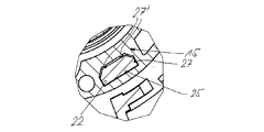
図面に示された装置10は、一例としてトラクターの椅子の肘掛けあるいはトラクターに農業器具を結合するための出力軸に対し、一つの軸12の周りに回転可能な要素11の同じ回転方向における90°あるいは180°以上、あるいはそれ以上の作動角度を調節および検出するためのものである。ここでは要素11を入力要素11と称する。作動角度の調節および検出は、ホールセンサーユニット13からなる磁界センサー装置および一つの環状の永久磁石14により行われ、それによって、駆動され、その作動角度が調整可能な部品が図示されていない方法により駆動され、あるいは調節される。単一の環状の永久磁石14は車輪形の入力要素11に配置されているのに対し、ホールセンサーユニット13はセンサーホルダー15に保持されている。センサーホルダー15に対向する車輪形の入力要素11はその中心の周りに、同じ方向に90°より大きいか、あるいは180°より大きい角度(図示された実施例では210°から220°まで)、例えば360°までも回転可能である。
The
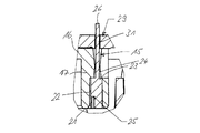
ほぼ深鍋が逆立ちした形状を有するセンサーホルダー15は合成物質製の一体物であり、底16と円周の側部17とが形成されている。センサーホルダー15の底16は、その中心を中空金属製の軸18が貫通しており、それによってこの軸18と固着している。中空の軸18の半径方向のフランジ19は底16に対して突出している。それによって、好適には鉄鋼製の中空の軸18の、センサーホルダー15に対する正確な位置決めが達成される。
The
センサーホルダー15の側部17は、実施例では二つの、90°よりも少し小さい、ここでは80°の角度間隔で互いに配置され、その軸方向の表面21に終端する空隙22を有する。この空隙22は環状スイッチ平面23上の軸方向において直径が小さい貫通穴24に繋がっている。この空隙22あるいは部屋にはそれぞれ、ホールセンサーユニット13の個々のホールセンサー25あるいは25´が組み込まれ、その接続足26は貫通穴24を貫通し、底16から突出している。それぞれのホールセンサー25、25´は空隙あるいは部屋22に正確に位置決めされて取り付けられている。そして、実施例では断面がほぼ台形状の空隙あるいは部屋22は、互いに垂直な二つの側面に突起27、27´が設けられており、それらの側面の間にホールセンサー25、25´が保持されている。それによって、ホールセンサー25、25´は部屋22の同じ角に常に押圧される。実施例では、部屋22の一つの短い側面に一つの突起27を有するとともに、それに対して直角に延びている長い側面に間隔を開けて配置された二つの突起27´を有する。部屋22の突起27、27´の数は他の方法によって決めることができることは当然である。
The
センサーホルダー15の底16には、部屋22と反対側に、印刷された導体板またシート29が設けられている。導体板またはシート29は、底16の軸方向の環状フランジと同心に配置されている。導体板またシート29は底16に固着している。導体板またはシート29の電気伝導性の穴31にホールセンサー25、25´の接続足26が挿入され、はんだ付けされている。それによって、共通の導体板またシート29の上にホールセンサー25、25´の電気回路が達している。
On the
実施例では、ただ二つだけのホールセンサー25、25´が90°よりも多少小さい、すなわちここでは80°の角度間隔で配置されているだけであるが、側面21の寸法に応じて、部屋22に相応の数、例えば三つあるいは四つのホールセンサー25を配置することができる。実施例による二つのホールセンサー25、25´は約210°から220°の角度範囲を、三つのホールセンサーは360°の角度範囲をカバーすることができる。360°の作動角度の冗長性のある評価は四つのホールセンサー25により達成することができる。
In the embodiment, only two
車輪形の入力要素11は、合成物質製の一体物からなる底36および取っ手(換言すればハンドル)37を有する。取っ手37は、下から上に向かって縮小する側面が形成される円錐形に反っており、センサーホルダー15を手で掴むためにこれに向かう側が開放している。
The wheel-
底36は一体物からなる内側ケース38を有する。この内側ケース38は底36の両面から軸方向に突出している。この場合、取っ手37の内側にあるケース部分39は取っ手37と反対側のケース部分40より長い。中心の内側ケース38はその内面が二つの滑りスリーブ41、42により囲まれている。二つの同一の滑りスリーブ41、42は、内側ケース38に沿って軸方向に間隔を空けて存在し、ケース部分39、40の環状の前面から軸方向の外側に突出した環状フランジ43あるいは44まで延びている。一つの最良の取り付けでは、両滑りスリーブ41、42を内側ケース38の中または上に圧迫する。
The
内側ケース38の、滑りスリーブ41、42と反対側の外周面と底の半径方向の外側の表面から軸方向に突出している環状フランジ45との間に、環状磁石の形態の永久磁石14が配置され、保持されている。環状永久磁石14は底36の環状の窪みにはめ込まれており、同心に貼り付けられている。この環状磁石はその上のより長いケース部分39の環状の前面の近くにまで延びている。
A
入力要素11は、中空の軸18の上の二つの滑りスリーブ41、42により、非常にわずかな遊びで回転可能になっている。これは、二つの滑りスリーブ41、42を焼結青銅スリーブにより形成することにより可能であり、鉄鋼製の中空の軸18との組み合わせによりこの非常に遊びの少ない軸受けが得られる。
The
入力要素11およびセンサーホルダー15の軸方向のかみ合いと永久磁石14およびホールセンサー25、25´の相応の配置とによって、半径方向も軸方向も正確な関係が得られ、それによって、ホールセンサー25、25´は半径方向に決まった間隔で、また、環状永久磁石14のほぼ中心の高さに配置される。
Due to the axial engagement of the
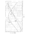
図示はしないが、主として金属シート29上にマイクロコントローラーが設けられている。このマイクロコントローラーの支援によって、作動角度を正確に検出するために、車輪形の入力要素11の現在の位置に対して、最も有利な位置にあるホールセンサー25あるいは25´がその都度選択される。それによって、二つのホールセンサー25、25´のどちらがアクティブであるか、あるいは、アクティブとしなければならないかが決定される。これは、図5のセンサー25(破線)および25´(一点鎖線)の特性曲線(作動角度に依存するデジタル変換された信号電圧)に図示されたところに従うと、マイクロコントローラーにより順次、ホールセンサー25、25´のどちらかが選択され、その特性曲線33(求められた直線)は対応する作動角度において直線の範囲にあり、その結果得られる、それらから合成された全体あるいは出力特性曲線33は、ほぼ210°から220°までの作動角度範囲において直線である。その際、どうしても必要であれば、切り換えによって、それぞれのホールセンサー25、25´に対して、あるいは、それぞれのホールセンサー25、25´から、最も直線に近い挙動を検出することができる。例えば、二つのホールセンサー25、25´の角度間隔が80°の場合、210°から220°までの角度範囲において特性曲線33の最高のあるいは最適化されたな直線性が得られる。
Although not shown, a microcontroller is mainly provided on the
加えて、マイクロコントローラーは、遷移領域、すなわちホールセンサー25からそれに最も近いホールセンサー25´への切り換え点において、出力特性曲線にジャンプが生じるのを防止する。これは、三つまたは四つのホールセンサーを用いる場合の360°の作動角度でも同様に有効であることは明らかである。
In addition, the microcontroller prevents jumps in the output characteristic curve at the transition region, i.e. the switching point from the
10…装置、11…入力要素、12…軸、13…ホールセンサーユニット、14…永久磁石、15…センサーホルダー、16…底、17…側部、18…軸、19…フランジ、21…表面、22…空隙、23…環状スイッチ平面、24…貫通穴、25、25´…ホールセンサー、26…接続足、27…突起、29…導体板またシート、36…底、37…取っ手、38…内側ケース、39、40…ケース部分、41、42…滑りスリーブ、43、44、45…環状フランジ
DESCRIPTION OF
Claims (20)
Applications Claiming Priority (2)
| Application Number | Priority Date | Filing Date | Title |
|---|---|---|---|
| DE102007024249A DE102007024249A1 (en) | 2007-05-18 | 2007-05-18 | Device for detecting a setting angle of an element rotatable about an axis |
| PCT/EP2008/003853 WO2008141758A2 (en) | 2007-05-18 | 2008-05-14 | Device for the detection of an actuation angle of an element rotatable about a shaft |
Publications (2)
| Publication Number | Publication Date |
|---|---|
| JP2010527445A true JP2010527445A (en) | 2010-08-12 |
| JP2010527445A5 JP2010527445A5 (en) | 2013-04-18 |
Family
ID=39941963
Family Applications (1)
| Application Number | Title | Priority Date | Filing Date |
|---|---|---|---|
| JP2010507839A Pending JP2010527445A (en) | 2007-05-18 | 2008-05-14 | Device for detecting the working angle of an element rotatable about one axis |
Country Status (9)
| Country | Link |
|---|---|
| US (1) | US20100289486A1 (en) |
| EP (1) | EP2149035B1 (en) |
| JP (1) | JP2010527445A (en) |
| CN (1) | CN101688788B (en) |
| CA (1) | CA2686972A1 (en) |
| DE (1) | DE102007024249A1 (en) |
| HK (1) | HK1139730A1 (en) |
| RU (1) | RU2494347C2 (en) |
| WO (1) | WO2008141758A2 (en) |
Cited By (1)
| Publication number | Priority date | Publication date | Assignee | Title |
|---|---|---|---|---|
| JP2015213424A (en) * | 2014-05-06 | 2015-11-26 | ジョンソン エレクトリック ソシエテ アノニム | Controller for driving stepper motor |
Families Citing this family (6)
| Publication number | Priority date | Publication date | Assignee | Title |
|---|---|---|---|---|
| WO2013152925A1 (en) * | 2012-04-11 | 2013-10-17 | Schaeffler Technologies AG & Co. KG | Determination of the position of a hydrostatic actuator |
| SE538779C2 (en) * | 2012-05-04 | 2016-11-22 | Leine & Linde Ab | Carrier ring for an encoder |
| US9803997B2 (en) | 2013-07-26 | 2017-10-31 | Bei Sensors & Systems Company, Inc. | System and method for determining absolute angular position of a rotating member |
| US9389283B2 (en) * | 2013-07-26 | 2016-07-12 | Sensata Technologies, Inc. | System and method for converting output of sensors to absolute angular position of a rotating member |
| DE102016217454A1 (en) * | 2016-09-13 | 2018-03-15 | Bos Gmbh & Co. Kg | vehicle seat |
| DE102018116998A1 (en) * | 2018-07-13 | 2020-01-16 | Jenoptik Automatisierungstechnik Gmbh | Sensor device for scanning laser processing of a workpiece by means of a laser beam deflected around a pivot point |
Citations (8)
| Publication number | Priority date | Publication date | Assignee | Title |
|---|---|---|---|---|
| JPH05119137A (en) * | 1991-01-29 | 1993-05-18 | Matsushita Electric Ind Co Ltd | Ferromagnetic thin-film resistance element |
| JP2001221655A (en) * | 2000-02-14 | 2001-08-17 | Sensatec Kk | Contactless variable voltmeter |
| JP2002233125A (en) * | 2001-01-29 | 2002-08-16 | Victor Co Of Japan Ltd | Spindle motor |
| JP2003501997A (en) * | 1999-05-29 | 2003-01-14 | ローベルト ボツシユ ゲゼルシヤフト ミツト ベシユレンクテル ハフツング | Commutator motor |
| JP2003149000A (en) * | 2001-11-19 | 2003-05-21 | Kayaba Ind Co Ltd | Rotation angle sensor |
| JP2004264167A (en) * | 2003-03-03 | 2004-09-24 | Midori Sokki:Kk | Rotation angle sensor |
| JP2005189053A (en) * | 2003-12-25 | 2005-07-14 | Aisin Seiki Co Ltd | Rotation angle sensor |
| JP2006071623A (en) * | 2004-08-06 | 2006-03-16 | Denso Corp | Device for detecting rotation angle |
Family Cites Families (16)
| Publication number | Priority date | Publication date | Assignee | Title |
|---|---|---|---|---|
| GB641189A (en) * | 1947-10-26 | 1950-08-09 | George Noel Du Terreaux Pownal | Improvements in and relating to movement and vibration dampers |
| US3786336A (en) * | 1972-04-11 | 1974-01-15 | Allied Chem | Apparatus for measuring the angular displacement and the angular velocity of a rotation member |
| DE19716985A1 (en) * | 1997-04-23 | 1998-10-29 | A B Elektronik Gmbh | Device for determining the position and / or torsion of rotating shafts |
| US6522130B1 (en) * | 1998-07-20 | 2003-02-18 | Uqm Technologies, Inc. | Accurate rotor position sensor and method using magnet and sensors mounted adjacent to the magnet and motor |
| US6225716B1 (en) * | 1998-12-15 | 2001-05-01 | Honeywell International Inc | Commutator assembly apparatus for hall sensor devices |
| DE19917467A1 (en) * | 1999-04-17 | 2000-11-16 | Bosch Gmbh Robert | Measuring device for contactless detection of an angle of rotation |
| JP2002542473A (en) * | 1999-04-21 | 2002-12-10 | ローベルト ボツシユ ゲゼルシヤフト ミツト ベシユレンクテル ハフツング | Measuring device for detecting rotation angle by non-contact method |
| DE19922215B4 (en) * | 1999-05-14 | 2012-01-19 | Kaco Gmbh + Co. | Device for detecting the rotational movement of a rotating part |
| EP1520346B1 (en) * | 2001-02-24 | 2008-01-23 | Marquardt GmbH | Device for adjustment of rotation angles |
| US6541959B2 (en) * | 2001-02-27 | 2003-04-01 | S & S Cycle, Inc. | Angular position sensing system with magnet and rotor arrangement |
| US7208939B2 (en) * | 2001-02-28 | 2007-04-24 | Bvr Technologies Co. | Methods and apparatus for sensing angular position and speed of a rotatable shaft utilizing linearized annular magnet and commutated ratiometric hall sensors |
| DE10133492A1 (en) | 2001-07-10 | 2003-01-30 | Itt Mfg Enterprises Inc | Foot or hand operated control module |
| JP3624880B2 (en) * | 2001-07-13 | 2005-03-02 | 日本精機株式会社 | Rotation detector |
| RU2260188C1 (en) * | 2004-01-26 | 2005-09-10 | Государственное образовательное учреждение Курский государственный технический университет ГОУ КурскГТУ | Contact-free automobile speed detector |
| US7466125B2 (en) * | 2004-07-12 | 2008-12-16 | Feig Electronic Gmbh | Position transmitter and method for determining a position of a rotating shaft |
| US7663274B2 (en) * | 2004-09-21 | 2010-02-16 | Nidec Corporation | Motor |
-
2007
- 2007-05-18 DE DE102007024249A patent/DE102007024249A1/en not_active Withdrawn
-
2008
- 2008-05-14 CN CN200880015766XA patent/CN101688788B/en not_active Expired - Fee Related
- 2008-05-14 US US12/600,815 patent/US20100289486A1/en not_active Abandoned
- 2008-05-14 RU RU2009144905/28A patent/RU2494347C2/en not_active IP Right Cessation
- 2008-05-14 WO PCT/EP2008/003853 patent/WO2008141758A2/en active Application Filing
- 2008-05-14 EP EP08758507.1A patent/EP2149035B1/en not_active Not-in-force
- 2008-05-14 CA CA002686972A patent/CA2686972A1/en not_active Abandoned
- 2008-05-14 JP JP2010507839A patent/JP2010527445A/en active Pending
-
2010
- 2010-06-30 HK HK10106394.7A patent/HK1139730A1/en not_active IP Right Cessation
Patent Citations (8)
| Publication number | Priority date | Publication date | Assignee | Title |
|---|---|---|---|---|
| JPH05119137A (en) * | 1991-01-29 | 1993-05-18 | Matsushita Electric Ind Co Ltd | Ferromagnetic thin-film resistance element |
| JP2003501997A (en) * | 1999-05-29 | 2003-01-14 | ローベルト ボツシユ ゲゼルシヤフト ミツト ベシユレンクテル ハフツング | Commutator motor |
| JP2001221655A (en) * | 2000-02-14 | 2001-08-17 | Sensatec Kk | Contactless variable voltmeter |
| JP2002233125A (en) * | 2001-01-29 | 2002-08-16 | Victor Co Of Japan Ltd | Spindle motor |
| JP2003149000A (en) * | 2001-11-19 | 2003-05-21 | Kayaba Ind Co Ltd | Rotation angle sensor |
| JP2004264167A (en) * | 2003-03-03 | 2004-09-24 | Midori Sokki:Kk | Rotation angle sensor |
| JP2005189053A (en) * | 2003-12-25 | 2005-07-14 | Aisin Seiki Co Ltd | Rotation angle sensor |
| JP2006071623A (en) * | 2004-08-06 | 2006-03-16 | Denso Corp | Device for detecting rotation angle |
Cited By (1)
| Publication number | Priority date | Publication date | Assignee | Title |
|---|---|---|---|---|
| JP2015213424A (en) * | 2014-05-06 | 2015-11-26 | ジョンソン エレクトリック ソシエテ アノニム | Controller for driving stepper motor |
Also Published As
| Publication number | Publication date |
|---|---|
| EP2149035B1 (en) | 2014-08-06 |
| CN101688788B (en) | 2013-11-06 |
| RU2009144905A (en) | 2011-06-27 |
| DE102007024249A1 (en) | 2008-12-11 |
| US20100289486A1 (en) | 2010-11-18 |
| EP2149035A2 (en) | 2010-02-03 |
| WO2008141758A2 (en) | 2008-11-27 |
| CA2686972A1 (en) | 2008-11-27 |
| RU2494347C2 (en) | 2013-09-27 |
| WO2008141758A3 (en) | 2009-03-19 |
| CN101688788A (en) | 2010-03-31 |
| HK1139730A1 (en) | 2010-09-24 |
Similar Documents
| Publication | Publication Date | Title |
|---|---|---|
| JP2010527445A (en) | Device for detecting the working angle of an element rotatable about one axis | |
| US8247935B2 (en) | Brushless motor stator with fitting position determining structure of circuit substrate | |
| JP2004309463A (en) | Instrument for measuring torque applied to shaft | |
| US10340773B2 (en) | Brushless motor having an outer rotor and an annular separation plate between the drive magnet and the position detection magnet | |
| JP2010160037A (en) | Rotation angle detector | |
| JP2008134250A (en) | Rotary encoder | |
| JP5617205B2 (en) | Encoder | |
| JP2010527445A5 (en) | ||
| JP2014229468A5 (en) | ||
| JP5684529B2 (en) | motor | |
| JP2009180499A (en) | Angle detection device | |
| US20190140524A1 (en) | Rotary position sensor including switch and patterned magnet | |
| KR102057327B1 (en) | Magnet holder mounting structure of shift actuator | |
| JP2011112471A (en) | Magnetic encoder and rotation detecting apparatus | |
| US9823146B2 (en) | Axial flux focusing small diameter low cost torque sensor | |
| JP2011033387A (en) | Angular detection sensor | |
| JP3214535B2 (en) | Pachinko ball launching strength adjustment device | |
| CN100399680C (en) | Rotor balance structure of motor | |
| US20070024143A1 (en) | Roatary electric machine with permanent-magnet rotor | |
| JP2018124248A (en) | Rotational position detection device and motor device | |
| JP3616284B2 (en) | Rotation detection sensor | |
| JP5440125B2 (en) | Encoder | |
| JP4383231B2 (en) | Non-contact position sensor | |
| JP2006017536A (en) | Rotation detection sensor and bearing with sensor using it | |
| JP2021048741A (en) | Motor, motor drive control device, and motor drive control method |
Legal Events
| Date | Code | Title | Description |
|---|---|---|---|
| A621 | Written request for application examination |
Free format text: JAPANESE INTERMEDIATE CODE: A621 Effective date: 20110328 |
|
| A977 | Report on retrieval |
Free format text: JAPANESE INTERMEDIATE CODE: A971007 Effective date: 20120629 |
|
| A131 | Notification of reasons for refusal |
Free format text: JAPANESE INTERMEDIATE CODE: A131 Effective date: 20120906 |
|
| A601 | Written request for extension of time |
Free format text: JAPANESE INTERMEDIATE CODE: A601 Effective date: 20121205 |
|
| A602 | Written permission of extension of time |
Free format text: JAPANESE INTERMEDIATE CODE: A602 Effective date: 20121212 |
|
| A601 | Written request for extension of time |
Free format text: JAPANESE INTERMEDIATE CODE: A601 Effective date: 20121228 |
|
| A602 | Written permission of extension of time |
Free format text: JAPANESE INTERMEDIATE CODE: A602 Effective date: 20130110 |
|
| A601 | Written request for extension of time |
Free format text: JAPANESE INTERMEDIATE CODE: A601 Effective date: 20130205 |
|
| A602 | Written permission of extension of time |
Free format text: JAPANESE INTERMEDIATE CODE: A602 Effective date: 20130213 |
|
| A524 | Written submission of copy of amendment under section 19 (pct) |
Free format text: JAPANESE INTERMEDIATE CODE: A524 Effective date: 20130304 |
|
| A711 | Notification of change in applicant |
Free format text: JAPANESE INTERMEDIATE CODE: A711 Effective date: 20130614 |
|
| A521 | Written amendment |
Free format text: JAPANESE INTERMEDIATE CODE: A821 Effective date: 20130614 |
|
| A131 | Notification of reasons for refusal |
Free format text: JAPANESE INTERMEDIATE CODE: A131 Effective date: 20140107 |
|
| A601 | Written request for extension of time |
Free format text: JAPANESE INTERMEDIATE CODE: A601 Effective date: 20140404 |
|
| A602 | Written permission of extension of time |
Free format text: JAPANESE INTERMEDIATE CODE: A602 Effective date: 20140411 |
|
| A601 | Written request for extension of time |
Free format text: JAPANESE INTERMEDIATE CODE: A601 Effective date: 20140502 |
|
| A602 | Written permission of extension of time |
Free format text: JAPANESE INTERMEDIATE CODE: A602 Effective date: 20140513 |
|
| A601 | Written request for extension of time |
Free format text: JAPANESE INTERMEDIATE CODE: A601 Effective date: 20140605 |
|
| A602 | Written permission of extension of time |
Free format text: JAPANESE INTERMEDIATE CODE: A602 Effective date: 20140612 |
|
| A02 | Decision of refusal |
Free format text: JAPANESE INTERMEDIATE CODE: A02 Effective date: 20140911 |