JP2010526261A - Swing bumper made by corrugated extrusion - Google Patents
Swing bumper made by corrugated extrusion Download PDFInfo
- Publication number
- JP2010526261A JP2010526261A JP2010506319A JP2010506319A JP2010526261A JP 2010526261 A JP2010526261 A JP 2010526261A JP 2010506319 A JP2010506319 A JP 2010506319A JP 2010506319 A JP2010506319 A JP 2010506319A JP 2010526261 A JP2010526261 A JP 2010526261A
- Authority
- JP
- Japan
- Prior art keywords
- bumper
- rocking
- swing
- thermoplastic
- extrusion
- Prior art date
- Legal status (The legal status is an assumption and is not a legal conclusion. Google has not performed a legal analysis and makes no representation as to the accuracy of the status listed.)
- Pending
Links
Images


Classifications
-
- F—MECHANICAL ENGINEERING; LIGHTING; HEATING; WEAPONS; BLASTING
- F16—ENGINEERING ELEMENTS AND UNITS; GENERAL MEASURES FOR PRODUCING AND MAINTAINING EFFECTIVE FUNCTIONING OF MACHINES OR INSTALLATIONS; THERMAL INSULATION IN GENERAL
- F16F—SPRINGS; SHOCK-ABSORBERS; MEANS FOR DAMPING VIBRATION
- F16F1/00—Springs
- F16F1/36—Springs made of rubber or other material having high internal friction, e.g. thermoplastic elastomers
- F16F1/373—Springs made of rubber or other material having high internal friction, e.g. thermoplastic elastomers characterised by having a particular shape
- F16F1/3732—Springs made of rubber or other material having high internal friction, e.g. thermoplastic elastomers characterised by having a particular shape having an annular or the like shape, e.g. grommet-type resilient mountings
-
- F—MECHANICAL ENGINEERING; LIGHTING; HEATING; WEAPONS; BLASTING
- F16—ENGINEERING ELEMENTS AND UNITS; GENERAL MEASURES FOR PRODUCING AND MAINTAINING EFFECTIVE FUNCTIONING OF MACHINES OR INSTALLATIONS; THERMAL INSULATION IN GENERAL
- F16F—SPRINGS; SHOCK-ABSORBERS; MEANS FOR DAMPING VIBRATION
- F16F1/00—Springs
- F16F1/36—Springs made of rubber or other material having high internal friction, e.g. thermoplastic elastomers
- F16F1/42—Springs made of rubber or other material having high internal friction, e.g. thermoplastic elastomers characterised by the mode of stressing
- F16F1/422—Springs made of rubber or other material having high internal friction, e.g. thermoplastic elastomers characterised by the mode of stressing the stressing resulting in flexion of the spring
- F16F1/424—Springs made of rubber or other material having high internal friction, e.g. thermoplastic elastomers characterised by the mode of stressing the stressing resulting in flexion of the spring of membrane-type springs
Abstract
本発明は、車両サスペンションシステム、特に、コルゲート押出しにより作製された揺動バンパーを提供する。 The present invention provides a vehicle suspension system, in particular a swing bumper made by corrugated extrusion.
Description
本発明は、車両サスペンションシステム、特に、揺動バンパーの分野に関する。 The present invention relates to the field of vehicle suspension systems, and more particularly to the field of swing bumpers.
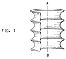
揺動バンパー(バンプストップ、エンド・オブ・トラベルバンパー、ストライク−アウトバンパー、サスペンションバンパーまたはコンプレッションバンパーとも呼ばれる)は、車両サスペンションの上部にある衝撃吸収部である。モーター車両サスペンションシステムに用いる揺動バンパーは、2つのサスペンションシステムコンポーネント、例えば、アクセルとフレームの一部との間の衝撃を緩衝し、乗員の乗り心地のために雑音と振動を抑えるべく長いこと用いられている。車両シャシーの変位により、ストラットも変位するため、ストラットは、車両シャシーの変位に応答して、圧縮と拡張のサイクルを受ける。サスペンションの過度な変位につながる、道路の激しい凹凸による揺動からストラットアセンブリおよび車体を保護するための対策を講じなければならない。このため、異常な走行条件で生じる力を衝撃吸収材が吸収できなかったときに衝撃が生じやすい場所で、サスペンションシステムに揺動バンパーが取り付けられている。特に、ストラットの揺動中、ダンパーが「底につき」、揺動バンパーは、揺動バンパープレートと接触するように動いて、圧縮されてエネルギーが消失される結果、衝撃を和らげ、雑音を減じ、乗客の衝撃感を減じ、車両サスペンションシステムへのダメージの可能性を減じる。揺動バンパーは、ピストンロッド周囲に延在する圧縮性およびエラストマー材料で作製されたコンボリュートのある、またはない、細長い、通常は円筒形の部材である。この用途に好適な材料は、弾性、すなわち、永久歪みまたは破壊なしに、衝撃に耐え得るものでなければならず、優れた曲げ寿命を有していなければならない。従来の揺動バンパーは、ポリウレタンおよびコポリエステルポリマーから作製されている。エラストマー材料で作製された典型的な揺動バンパーを図1に示す。 A rocking bumper (also called a bump stop, end-of-travel bumper, strike-out bumper, suspension bumper or compression bumper) is an impact absorber at the top of the vehicle suspension. Swing bumpers used in motor vehicle suspension systems are used long enough to damp shocks between two suspension system components, for example, the accelerator and part of the frame, and to reduce noise and vibration for passenger comfort It has been. Since the struts are displaced by the displacement of the vehicle chassis, the struts undergo a compression and expansion cycle in response to the displacement of the vehicle chassis. Measures must be taken to protect the strut assembly and the vehicle body from rocking due to severe bumps in the road leading to excessive displacement of the suspension. For this reason, the swing bumper is attached to the suspension system at a place where an impact is likely to be generated when the impact absorbing material cannot absorb the force generated under abnormal traveling conditions. In particular, during strut swinging, the damper is "bottomed" and the swinging bumper moves into contact with the swinging bumper plate, compressing and losing energy resulting in cushioning and noise reduction. Reduces passenger impact and reduces the possibility of damage to the vehicle suspension system. A rocking bumper is an elongated, usually cylindrical member with or without a convolute made of compressible and elastomeric material that extends around the piston rod. A suitable material for this application must be resilient, i.e. capable of withstanding impact without permanent set or fracture, and have an excellent bending life. Conventional swing bumpers are made from polyurethane and copolyester polymers. A typical swing bumper made of an elastomeric material is shown in FIG.
揺動バンパーは、従来、ポリウレタン、特に、マイクロセルラーポリウレタン(MCU)で形成されている。マイクロセルラーポリウレタン揺動バンパーは、揺動バンパー鋳型においてポリウレタン前駆体を成形することにより作製される。マイクロセルラー発泡体は、ジイソシアネートグリコールと、発泡用の二酸化炭素ガスを生成する発泡剤または水との反応により得られる。二酸化炭素は徐放されるため、発泡には、鋳型において、長い時間が必要であるため、この技術は時間がかかるものである。発泡ポリウレタンで作製された揺動バンパーは、良好な乗車特性を有するが、時間のかかる技術が必要であるため、製造に費用がかかる。 The swing bumper is conventionally formed of polyurethane, in particular, microcellular polyurethane (MCU). The microcellular polyurethane swing bumper is produced by molding a polyurethane precursor in a swing bumper mold. Microcellular foams are obtained by reaction of diisocyanate glycol with a blowing agent or water that produces carbon dioxide gas for foaming. This technique is time consuming because carbon dioxide is released slowly and foaming requires a long time in the mold. A swing bumper made of foamed polyurethane has good riding characteristics, but requires time-consuming techniques and is expensive to manufacture.
耐久性、自動車流体に対する不活性さ、揺動バンパーを形成するのに用いる材料の引き裂き伝播に対する抵抗性を改善するために、米国特許第5192057号明細書には、エラストマー、好ましくは、コポリエーテルエステルポリマーで形成された細長い中空体が開示されている。かかるピースは、ブロー成形技術により製造される。 To improve durability, inertness to automotive fluids, and resistance to tear propagation of materials used to form rocking bumpers, US Pat. No. 5,192,057 describes elastomers, preferably copolyetheresters. An elongated hollow body formed of a polymer is disclosed. Such pieces are manufactured by blow molding techniques.
ブロー成形は、中空プラスチック物品を製造するのに用いる従来の技術である。典型的に、押出しまたは射出成形により製造され、熱成形可能な状態にあるプラスチック材料のパリソンを、製造する物品の必要な外側形状に適した形状の鋳型キャビティを有する二等分の開いたブロー鋳型間に配置する。パリソンは、重力の影響下、徐々に降下し、伸長する。パリソンが適正な長さに達すると、鋳型の半分をその周囲で閉じ、加圧空気またはその他圧縮ガスを、パリソン内部に導入して、鋳型の形状まで膨らます、または鋳型キャビティの側部に対して膨張させる。冷却期間後、鋳型を開き、最終物品を取り出す。 Blow molding is a conventional technique used to produce hollow plastic articles. Typically, a plastic material parison made by extrusion or injection molding and in a thermoformable state is a bisection open blow mold with a mold cavity shaped to suit the required outer shape of the article being manufactured Place between. The parison gradually descends and expands under the influence of gravity. When the parison reaches the proper length, half of the mold is closed around it and pressurized air or other compressed gas is introduced inside the parison to expand to the shape of the mold, or against the side of the mold cavity Inflate. After the cooling period, the mold is opened and the final article is removed.
押出しブロー成形においては、パリソンは押出し機により製造される。押出しブロー成形は、発泡/鋳造より安価であるが、正確な寸法になり難く、部品の壁厚さの制限にもつながる。揺動バンパーの剛性は、その厚さに直接関係する。このように、例えば、0.2mmといった厚さの小さな変動(ワンショットで作製された揺動バンパーの長手方向軸に沿った、または単一の揺動バンパーで作製された揺動バンパーのコンボリュート半径に沿った、物品毎の変動)が、揺動バンパーの剛性ならびにそのエネルギー吸収能および減衰性能を大きく変える。 In extrusion blow molding, the parison is manufactured by an extruder. Extrusion blow molding is less expensive than foaming / casting, but is less accurate and leads to a limit on the wall thickness of the part. The stiffness of the swing bumper is directly related to its thickness. Thus, for example, a small variation in thickness of 0.2 mm (a convolution of a swing bumper along the longitudinal axis of a swing bumper made in one shot or made with a single swing bumper Variation from article to article along the radius) greatly changes the stiffness of the swing bumper and its energy absorption and damping performance.
射出ブロー成形は、押出しブロー成形よりも正確な寸法を与える。この技術において、パリソンは射出成形により形成され、鋳型の内核が除去され、パリソンは即時に膨らむ。このとき、押出しブロー成形と同様に、二等分された鋳型に密閉されたままである。パリソンを射出成形すると、一定でない断面が得られ、押出しブロー成形よりも最終部品の壁厚均一性が良好となる。射出ブロー成形によって、最終ブローン構造に、より正確な細部が得られるが、押出しブロー成形より高価である。 Injection blow molding gives more accurate dimensions than extrusion blow molding. In this technique, the parison is formed by injection molding, the inner core of the mold is removed, and the parison expands immediately. At this time, like the extrusion blow molding, it remains sealed in the bisected mold. When the parison is injection molded, a non-constant cross section is obtained and the wall thickness uniformity of the final part is better than extrusion blow molding. Injection blow molding provides more accurate details in the final blown structure, but is more expensive than extrusion blow molding.
揺動バンパーを効率的かつ経済的に容易に製造する方法を見出すことが現在必要とされている。 There is a current need to find a method for easily and economically manufacturing a swing bumper.
本発明者らは、明確な制御された寸法および優れた性能特性を有する揺動バンパーを、コルゲート押出しにより経済的に作製できることを見出した。 The inventors have found that rocking bumpers with well-defined controlled dimensions and excellent performance characteristics can be made economically by corrugated extrusion.
第1の態様において、本発明は、1000s-1の剪断速度およびポリマー融点またはそれより約30℃高い処理温度のもとでISO 11443:2005(E)に準拠して測定された275Pa・sを超える見かけ粘度を有する熱可塑性エラストマーで作製された揺動バンパーを提供する。 In a first aspect, the present invention provides 275 Pa · s measured according to ISO 11443: 2005 (E) under a shear rate of 1000 s −1 and a polymer melting point or a processing temperature about 30 ° C. higher. A rocking bumper made of a thermoplastic elastomer having an apparent viscosity exceeding is provided.
第2の態様において、本発明は、コルゲート押出しを用いて揺動バンパーを製造するプロセスを提供する。 In a second aspect, the present invention provides a process for manufacturing a rocking bumper using corrugated extrusion.
本明細書で参照した文献は全て、参考文献として援用される。 All documents referred to in this specification are incorporated by reference.
コルゲート押出しとは、材料の中空管を、押出しダイから押出し、中空管を、通常、鋳型において操作して、周囲コルゲート加工、ベローズまたはコンボリュートを形成するものである。材料の中空管は、鋳型キャビティの表面に対する、熱風か、真空膨張のいずれかにより、揺動バンパー物品へと成形される。本発明による揺動バンパーを製造するプロセスは、
a)溶融プラスチック材料を押出し機に供給する工程と、
b)熱成形可能な状態にあるプラスチック材料を、押出しヘッドのピンおよびダイを通して押出して、中空連続管を形成する工程と、
c)中空連続管をコルゲート加工する工程と、
d)鎖状につながった多数の揺動バンパーを切断して、単一の不連続な揺動バンパーを形成する工程、
または、保管のために、多数の揺動バンパーの連続コルゲート管を巻き上げて、後の段階で切断する工程と
を含む。
Corrugated extrusion is the extrusion of a hollow tube of material from an extrusion die, which is usually manipulated in a mold to form a surrounding corrugated, bellows or convolute. The hollow tube of material is formed into an oscillating bumper article by either hot air or vacuum expansion to the surface of the mold cavity. The process of manufacturing a rocking bumper according to the present invention comprises:
a) supplying molten plastic material to an extruder;
b) extruding the plastic material in a thermoformable state through pins and dies of an extrusion head to form a hollow continuous tube;
c) corrugating the hollow continuous tube;
d) cutting a large number of swing bumpers connected in a chain to form a single discontinuous swing bumper;
Or, for storage, a step of winding up a continuous corrugated tube of a large number of swing bumpers and cutting at a later stage.
コルゲート押出しの好ましい方法は、
a)溶融プラスチック材料を押出し機に供給する工程と、
b)熱成形可能な状態にあるプラスチック材料を、押出しヘッドのピンおよびダイを通して押出して、中空連続管を形成する工程と、
c)中空連続管を鋳型ブロックに通し、溶融材料を、鋳型キャビティ表面またはコルゲータに対して引き上げ、真空膨張する工程と、
d)多数の揺動バンパーの連続コルゲート管を交差方向に切断して、単一の不連続な揺動バンパーを形成する工程、
または、保管のために、多数の揺動バンパーの連続コルゲート管を巻き上げて、後の段階で切断する工程と
からなる真空コルゲート押出しである。
The preferred method of corrugated extrusion is:
a) supplying molten plastic material to an extruder;
b) extruding the plastic material in a thermoformable state through pins and dies of an extrusion head to form a hollow continuous tube;
c) passing the hollow continuous tube through the mold block, pulling the molten material against the mold cavity surface or corrugator and vacuum expanding;
d) cutting a continuous corrugated tube of multiple swing bumpers in the cross direction to form a single discontinuous swing bumper;
Or it is vacuum corrugated extrusion which consists of the process of winding up the continuous corrugated pipe | tube of many rocking bumpers for a storage, and cut | disconnecting at a later stage.
コルゲート加工機は、連続的に水冷される一連の相互接続鋳型ブロックを含む2組の交換可能な相補的鋳型組立て品で作製された鋳型トンネルを含む。鋳型ブロックは、ピンおよびダイヘッドに対して、コンベヤートラック上を連続的に動き、やや高速で揺動バンパーを連続的に製造することができる。例えば、ブロー成形法では、1分当たり約4つの揺動バンパーが製造できるが、コルゲート押出しだと、はるかに速い速度(例えば、1分当たり20、30または40を超える)で製造できる。コルゲート押出しは、Corelco(France)製の機械を用いることにより行える。機械および方法は、参考文献として援用される欧州特許公開第0909629号明細書および欧州特許公開第0734 835号明細書に開示されている。 The corrugating machine includes a mold tunnel made of two sets of interchangeable complementary mold assemblies that include a series of interconnected mold blocks that are continuously water cooled. The mold block moves continuously on the conveyor track with respect to the pins and the die head, and the swing bumper can be continuously manufactured at a slightly high speed. For example, the blow molding process can produce about 4 rocking bumpers per minute, but corrugated extrusion can be produced at much faster speeds (eg, greater than 20, 30 or 40 per minute). Corrugated extrusion can be performed by using a machine manufactured by Corelco (France). Machines and methods are disclosed in EP 0909629 and EP 0734 835, which are incorporated by reference.
押出し/射出ブロー成形といった従来の技術により作製された揺動バンパーに比べて、本発明により作製された物品は、連続プロセスで製造するのに単純で費用効率が高いばかりでなく、明確に制御された寸法および優れた性能特性という点で高品質でもある。さらに、本発明によるコルゲート押出しにより作製された揺動バンパーの設計可能性、例えば、コンボリュートの高さ、外径寸法または内径寸法を、容易に変更でき、従来の技術と比較して、再設計の場合に開始プロセスがより早くなる。本発明による揺動バンパーの幾何形状を修正して、特定の用途について、機械的特性およびエネルギー吸収性能を微調整してもよい。好ましくは、本発明による揺動バンパーは、10〜20kNまたは約10〜約20kNの最大圧縮軸力を有する。また、好ましくは、本発明による揺動バンパーは、(圧縮高さ/未圧縮高さ)×100%で測定すると、最大圧縮軸力下で30%〜90%または約30%〜約90%、好ましくは70%〜80%または約70%〜約80%の圧縮率を有する。本発明による揺動バンパーの修正には、例えば、揺動バンパーの壁厚(図2、T)を均一にする、または不均一にすること、山の直径/半径(図2、Rext)および谷の直径/半径(図2、Rint)を変えることにより、ベローズ/コンボリュートの数を変えることにより、ピッチを変えることにより、ベローズの最低外径でのフィレット半径(図2、rc)およびベローズの最大外径でのフィレット半径(図2、rs)を変えることにより、山の直径対谷の直径の比を変えることが含まれる。これらの変更はいずれも、本発明のコルゲート押出し技術により比較的容易に行うことができる。本発明による揺動バンパーの断面形状は特に限定されず、好ましい形状は円形および/または楕円形である。本発明による揺動バンパーは、全長に沿って周囲コルゲート加工、ベローズまたはコンボリュートを含む、または、平滑な領域で中断されたコルゲート加工、ベローズまたはコンボリュートを含むことができる。 Compared to oscillating bumpers made by conventional techniques such as extrusion / injection blow molding, the articles made by the present invention are not only simple and cost-effective to manufacture in a continuous process, but also are clearly controlled. High quality in terms of size and excellent performance characteristics. In addition, the design possibilities of swing bumpers made by corrugated extrusion according to the present invention, such as the height, outer diameter or inner diameter of the convolute, can be easily changed, redesigned compared to conventional techniques The start process is faster in the case of. The rocking bumper geometry according to the present invention may be modified to fine tune the mechanical properties and energy absorption performance for a particular application. Preferably, the rocking bumper according to the present invention has a maximum compression axial force of 10-20 kN or about 10 to about 20 kN. Also preferably, the rocking bumper according to the present invention has 30% to 90% or about 30% to about 90% under the maximum compression axial force when measured by (compressed height / uncompressed height) × 100%. Preferably it has a compression ratio of 70% to 80% or about 70% to about 80%. Modifications of the swing bumper according to the invention include, for example, making the wall thickness (FIG. 2, T) of the swing bumper uniform or non-uniform, the diameter / radius of the peaks (FIG. 2, R ext ) and By changing the valley diameter / radius (FIG. 2, R int ), by changing the number of bellows / convolute, by changing the pitch, the fillet radius at the lowest outer diameter of the bellows (FIG. 2, rc) and Changing the fillet radius at the maximum outer diameter of the bellows (FIG. 2, rs) involves changing the ratio of peak diameter to valley diameter. Any of these changes can be made relatively easily by the corrugated extrusion technique of the present invention. The cross-sectional shape of the swing bumper according to the present invention is not particularly limited, and a preferable shape is a circle and / or an ellipse. A rocking bumper according to the present invention can include a corrugating, bellows or convolute surrounding the entire length, or a corrugating, bellows or convoluting interrupted in a smooth area.
本発明の揺動バンパーは、いくつかの方法で、従来の(例えば、鋳造またはブロー成形)揺動バンパーと見分けることができる。 The swing bumper of the present invention can be distinguished from a conventional (eg, cast or blow molded) swing bumper in several ways.
a)壁厚均一性および比直径
必要であれば、材料を揺動バンパーの形状へとコルゲート押出しすると、厚さの均一な側壁を有するピースとなる。均一な厚さとは、揺動バンパー毎の揺動バンパーの壁厚さが均一であること(プロセスの再現性)、例えば、コンボリュートの全周囲に沿った単一の揺動バンパー内の壁厚さが均一であること、物品の全長に沿った揺動バンパーの壁厚さが均一であること(揺動バンパーが、ピースの全長に沿って均一な壁厚さを有するとき)を意味する。揺動バンパーの壁厚さが極めて均一であると、使用の際の変形が良好に均一となり、例えば、良好な機械的特性、より均一な剛性および寿命の増大等揺動バンパーの特性が改善される。単一の揺動バンパーのコンボリュートの全周囲に沿って、あるいは物品の全長に沿って不均一な壁厚が必要なときは、コルゲート押出しによって厚さの高レベルの制御が行える。
a) Wall thickness uniformity and specific diameter If necessary, the material is corrugated and extruded into the shape of a rocking bumper into a piece with sidewalls of uniform thickness. Uniform thickness means that the wall thickness of the oscillating bumper for each oscillating bumper is uniform (process repeatability), for example, the wall thickness within a single oscillating bumper along the entire circumference of the convolution. Means that the wall thickness of the swing bumper along the entire length of the article is uniform (when the swing bumper has a uniform wall thickness along the entire length of the piece). If the wall thickness of the swing bumper is extremely uniform, the deformation during use will be uniform, and the swing bumper characteristics such as good mechanical properties, more uniform rigidity and increased life will be improved. The When non-uniform wall thickness is required along the entire perimeter of a single rocking bumper convolution or along the entire length of the article, a high level of thickness control can be provided by corrugated extrusion.
揺動バンパーは、間隔をあけた複数の谷と山(図2、a)山およびb)谷、を参照)を周囲に有するベローズ形態で作製される。コルゲート押出しによって山の直径対谷の直径の比が特に高い、すなわち、1.2または約1.2より高い比を有する揺動バンパーが製造できる。かかる高い比によって、コンボリュートが深くなり、高度の可撓性が可能となる。かかる比と、壁厚の均質な均一性の組み合わせは、従来の技術では得られない。 The oscillating bumper is made in the form of a bellows having a plurality of spaced valleys and peaks (see FIG. 2, a) peaks and b) valleys). Corrugated extrusion can produce a rocking bumper with a particularly high ratio of peak diameter to valley diameter, i.e. a ratio higher than 1.2 or about 1.2. Such a high ratio deepens the convolution and allows a high degree of flexibility. The combination of such a ratio with a uniform uniformity of wall thickness is not possible with the prior art.
b)様々な材料
ブロー成形等の従来の技術では、溶融ポリマーは、1000s-1の剪断速度およびポリマー融点またはそれより約30℃高い処理温度のもとでISO 11443:2005(E)に準拠して測定された350Pa・sを超える見かけ粘度を有していなければならない。かかる高い見かけ粘度がブロー成形には必要である。パリソンは、ダイから出てくると自由懸垂されていて、このフェーズの最中に、制御できずに伸長または垂下することなく、自重に耐えなければならないからである。このことで、ブロー成形揺動バンパーの製造に用いることのできる材料が限定される。これとは対照的に、本発明の方法による揺動バンパーの製造には、様々な材料を選ぶことができる。
b) Various materials In conventional techniques such as blow molding, the molten polymer conforms to ISO 11443: 2005 (E) under a shear rate of 1000 s −1 and a polymer melting point or a processing temperature about 30 ° C. higher. Must have an apparent viscosity of greater than 350 Pa · s. Such a high apparent viscosity is necessary for blow molding. This is because the parison is free suspended when it comes out of the die and must withstand its own weight during this phase without uncontrollable stretching or drooping. This limits the materials that can be used to manufacture blow molded swing bumpers. In contrast, various materials can be selected for the manufacture of the swing bumper according to the method of the invention.
本発明の方法に用いることのできる材料は、可撓性および耐疲労性を必要とする。本発明に用いる材料の好適な例としては、熱可塑性エラストマーが挙げられる。溶融処理性の利便性に加えて、再利用できることから、環境上の理由からも熱可塑性エラストマーは好ましい。これとは対照的に、揺動バンパーを作製するのに従来から用いられている熱硬化材、特に、架橋ポリウレタンまたは架橋ゴムは再利用できない。 Materials that can be used in the method of the present invention require flexibility and fatigue resistance. A suitable example of the material used in the present invention is a thermoplastic elastomer. In addition to the convenience of melt processability, thermoplastic elastomers are preferred for environmental reasons because they can be reused. In contrast, thermosetting materials conventionally used to make oscillating bumpers, particularly crosslinked polyurethane or crosslinked rubber, cannot be reused.
本発明に有用な熱可塑性エラストマーとしては、ISO 18064:2003(E)に定義されているものが挙げられ、例えば、熱可塑性ポリオレフィンエラストマー(TPO)、スチレン熱可塑性エラストマー(TPS)、熱可塑性ポリエーテルまたはポリエステルポリウレタン(TPU)、熱可塑性加硫物(TPV)、熱可塑性ポリアミドブロックコポリマー(TPA)、コポリエステル熱可塑性エラストマー(TPC)、例えば、コポリエーテルエステルまたはコポリエステルエステルおよびこれらの混合物が挙げられ、同じく好適な材料は、熱可塑性ポリエステルおよびこれらの混合物である。 Thermoplastic elastomers useful in the present invention include those defined in ISO 18064: 2003 (E), such as thermoplastic polyolefin elastomer (TPO), styrene thermoplastic elastomer (TPS), thermoplastic polyether. Or polyester polyurethane (TPU), thermoplastic vulcanizates (TPV), thermoplastic polyamide block copolymers (TPA), copolyester thermoplastic elastomers (TPC), such as copolyetheresters or copolyesteresters and mixtures thereof. Also suitable materials are thermoplastic polyesters and mixtures thereof.
本発明による揺動バンパーはまた、1000s-1の剪断速度およびポリマー融点またはそれより約30℃高い処理温度のもとでISO 11443:2005(E)に準拠して測定された275Pa・sを超える見かけ粘度を有する熱可塑性エラストマーで作製してもよい。好ましくは、熱可塑性エラストマーは、1000s-1の剪断速度およびポリマー融点またはそれより約30℃高い処理温度のもとでISO 11443:2005(E)に準拠して測定された300Pa・sを超える見かけ粘度を有する。 The rocking bumper according to the invention also exceeds 275 Pa · s measured according to ISO 11443: 2005 (E) under a shear rate of 1000 s −1 and a polymer melting point or a processing temperature about 30 ° C. higher. It may be made of a thermoplastic elastomer having an apparent viscosity. Preferably, the thermoplastic elastomer appears to exceed 300 Pa · s measured according to ISO 11443: 2005 (E) under a shear rate of 1000 s −1 and a polymer melting point or a processing temperature about 30 ° C. higher. Has viscosity.
熱可塑性ポリオレフィンエラストマー(TPO)は、オレフィンタイプ、例えば、ゴムと、ポリプロピレンまたはポリエチレンからなる。一般的なゴムとしては、EPR(エチレン−プロピレンゴム)、EPDM(エチレンプロピレンジエンゴム)、エチレン−ヘキサン、エチレン−オクテン(例えば、Dowより市販されているEngage(登録商標))およびエチレン−ブタジエンが挙げられる。 Thermoplastic polyolefin elastomers (TPO) are of olefin type, for example rubber and polypropylene or polyethylene. Common rubbers include EPR (ethylene-propylene rubber), EPDM (ethylene propylene diene rubber), ethylene-hexane, ethylene-octene (eg Engage (registered trademark) commercially available from Dow) and ethylene-butadiene. Can be mentioned.
スチレン熱可塑性エラストマー(TPS)は、ポリスチレンとゴム状ポリマー材料、例えば、ポリブタジエン、水素化ポリブタジエンとポリブタジエンの混合物、ポリ(エチレン−プロピレンおよび水素化ポリイソプレン、のブロックコポリマーからなる。 Styrene thermoplastic elastomers (TPS) consist of block copolymers of polystyrene and rubbery polymeric materials such as polybutadiene, a mixture of hydrogenated polybutadiene and polybutadiene, poly (ethylene-propylene and hydrogenated polyisoprene).
熱可塑性ポリウレタン(TPU)は、一般式 Thermoplastic polyurethane (TPU) has the general formula

で表わされるジイソシアネートと短鎖グリコールを含む硬質およびジイソシアネートと長鎖ポリオールを含む軟質セグメントで構成された鎖状セグメントブロックコポリマーからなる。 And a linear segment block copolymer composed of a hard segment containing a diisocyanate and a short chain glycol and a soft segment containing a diisocyanate and a long chain polyol.
式中、「X」はジイソシアネートと短鎖グリコールを含む硬質セグメントを表わし、「Z」はジイソシアネートと長鎖ポリオールを含む軟質セグメントを表わし、「Y」はXおよびZセグメントをつなぐウレタン結合のジイソシアネート化合物の残基を表わす。長鎖ポリオールには、ポリ(アルキレンオキシド)グリコール等のポリエーテルタイプのもの、またはポリエステルタイプのものが含まれる。 In the formula, “X” represents a hard segment containing a diisocyanate and a short chain glycol, “Z” represents a soft segment containing a diisocyanate and a long chain polyol, and “Y” represents a urethane-linked diisocyanate compound connecting the X and Z segments. Represents the residue. Long chain polyols include those of the polyether type, such as poly (alkylene oxide) glycol, or those of the polyester type.
熱可塑性加硫物(TPV)は、加硫エラストマー相が分散された連続熱可塑性相からなる。本明細書で用いる加硫物および「加硫物ゴム」という言い回しは、硬化または部分硬化架橋または架橋可能ゴム、架橋ゴムの硬化可能前駆体の総称であり、それ自体が、エラストマー、ガムゴムおよびいわゆる軟質加硫物を含む。TPVは、架橋ゴムの多くの望ましい特性を、熱可塑性エラストマーの処理性等いくつかの特性と共に兼ね備えている。いくつかの市販のTPVがあり、例えば、Santoprene(登録商標)およびSarlink(登録商標)(エチレン−プロピレン−ジエンコポリマーおよびポリプロピレン系TPV)、それぞれ、Advanced Elastomer System’s and DSMより市販、Nextrile(登録商標)(ニトリルゴムおよびポリプロピレン系TPV)、Thermoplastic Rubber Systemsより入手可能、Zeotherm(登録商標)(アクリレートエラストマーおよびポリアミド系TPV)、Zeon Chemicalsより市販、およびE.I.du Pont de Nemours and Company製DuPont(登録商標)ETPV、国際特許出願第2004029155号明細書に記載されている(15〜60重量%のポリアルキレンフタレートポリエステルポリマーまたはコポリマーおよび40〜85重量%の架橋可能ポリ(メタ)アクリレートまたはポリエチレン/(メタ)アクリレートゴム分散相を含む熱可塑性ブレンドで、ゴムは、過酸化物フリーラジカル開始剤および有機ジエン助剤と動的に架橋される)。 Thermoplastic vulcanizate (TPV) consists of a continuous thermoplastic phase in which a vulcanized elastomer phase is dispersed. As used herein, the term vulcanizate and “vulcanized rubber” is a generic term for cured or partially cured crosslinked or crosslinkable rubbers, curable precursors of crosslinked rubbers, as such, elastomers, gum rubbers and so-called Includes soft vulcanizates. TPV combines many desirable properties of crosslinked rubber with several properties such as the processability of thermoplastic elastomers. There are several commercially available TPVs, for example, Santoprene® and Sarlink® (ethylene-propylene-diene copolymer and polypropylene-based TPV), respectively, available from Advanced Elastomer System's and DSM, Nexttri® Trademark) (nitrile rubber and polypropylene-based TPV), available from Thermoplastic Rubber Systems, Zeotherm® (acrylate elastomer and polyamide-based TPV), commercially available from Zeon Chemicals, and E.I. I. DuPont® ETPV from du Pont de Nemours and Company, described in International Patent Application No. 2004029155 (15-60 wt% polyalkylene phthalate polyester polymer or copolymer and 40-85 wt% crosslinkable In thermoplastic blends comprising a poly (meth) acrylate or polyethylene / (meth) acrylate rubber dispersed phase, the rubber is dynamically crosslinked with a peroxide free radical initiator and an organic diene aid).
熱可塑性ポリアミドブロックコポリマー(TPA)は、一般式 Thermoplastic polyamide block copolymer (TPA) has the general formula
で表わされるポリアミドセグメントおよび可撓性ポリエーテルまたはポリエステルセグメントまたはエーテルとエステル結合の両方を備えた軟性セグメントの鎖状および通常鎖からなる。 And a flexible polyether or polyester segment, or a flexible segment with both ether and ester linkages, and a regular chain.
式中、「PA」は鎖状飽和脂肪族ポリアミドシーケンスを表わし、「PE」は例えば、鎖状または分岐脂肪族ポリオキシアルキレングリコールまたはエーテルかエステルまたは両結合を有する長鎖ポリオールおよびこれらの混合物またはそれから誘導されたコポリエーテルコポリエステルから形成されたポリオキシアルキレンシーケンスを表わす。コポリエーテルアミドまたはコポリエステルアミドブロックコポリマーの軟性は、ポリアミド単位の相対量が増大するにつれ、概して、減少する。 Where “PA” represents a chain saturated aliphatic polyamide sequence and “PE” is, for example, a chain or branched aliphatic polyoxyalkylene glycol or an ether or ester or a long chain polyol having both bonds and mixtures thereof or It represents a polyoxyalkylene sequence formed from a copolyether copolyester derived therefrom. The softness of the copolyetheramide or copolyesteramide block copolymer generally decreases as the relative amount of polyamide units increases.
本発明に用いる熱可塑性ポリアミドブロックコポリマーの好適な例は、ArkemaまたはElf Atochemより、Pebax(登録商標)という商品名で市販されている。 Suitable examples of thermoplastic polyamide block copolymers for use in the present invention are commercially available from Arkema or Elf Atochem under the trade name Pebax®.
耐油性、高温耐久性および低温可撓性の優れた釣り合いのために、本発明による揺動バンパーは、熱可塑性ポリエステル組成物から作製してもよい。好ましい熱可塑性ポリエステルは、典型的に、1種類以上のジカルボン酸(本明細書で用いる「ジカルボン酸」という用語はまた、エステル等のジカルボン酸誘導体も指す)および1種類以上のジオールから誘導される。好ましいポリエステルにおいて、ジカルボン酸は、テレフタル酸、イソフタル酸および2,6−ナフタレンジカルボン酸のうち1つ以上を含み、ジオール成分は、HO(CH2)nOH(I)、1,4−シクロヘキサンジメタノール、HO(CH2CH2O)mCH2CH2OH(II)およびHO(CH2CH2CH2CH2O)zCH2CH2CH2CH2OH(III)(式中、nは2〜10の整数、mは平均で1〜4、zは平均で約7〜約40)のうち1つ以上を含む。(II)および(III)は、化合物の混合物であってもよく、mおよびzはそれぞれ異なっていてもよく、mおよびzは平均であるため、整数とはならないことに注意する。熱可塑性ポリエステルを形成するのに用いてよい他のジカルボン酸としては、セバシンおよびアジピン酸が挙げられる。ヒドロキシ安息香酸等のヒドロキシカルボン酸をコモノマーとして用いてもよい。好ましいポリエステルとしては、ポリ(エチレンテレフタレート)(PET)、ポリ(トリメチレンテレフタレート)(PTT)、ポリ(1,4−ブチレンテレフタレート)(PBT)、ポリ(エチレン2,6−ナフトアート)およびポリ(1,4−シクロヘキシルジメチレンテレフタレート)(PCT)が具体的に挙げられる。好ましくは、本発明に有用な熱可塑性ポリエステルは、衝撃改質剤および/または可塑剤をさらに含有する。
For a good balance of oil resistance, high temperature durability and low temperature flexibility, the rocking bumper according to the present invention may be made from a thermoplastic polyester composition. Preferred thermoplastic polyesters are typically derived from one or more dicarboxylic acids (the term “dicarboxylic acid” as used herein also refers to dicarboxylic acid derivatives such as esters) and one or more diols. . In a preferred polyester, the dicarboxylic acid comprises one or more of terephthalic acid, isophthalic acid and 2,6-naphthalenedicarboxylic acid, and the diol component is HO (CH 2 ) n OH (I), 1,4-cyclohexanedi methanol, HO (CH 2 CH 2 O ) m
コポリエステル熱可塑性エラストマー(TPC)、例えば、コポリエーテルエステルまたはコポリエステルエステルは、エステル結合により頭−尾がつながれた多数の繰り返し長鎖エステル単位および短鎖エステル単位を有するコポリマーであり、該長鎖エステル単位は、式(A) Copolyester thermoplastic elastomers (TPCs), such as copolyetheresters or copolyesteresters, are copolymers having a large number of repeating long-chain ester units and short-chain ester units linked head-to-tail by ester bonds, The ester unit is represented by the formula (A)
式中、Gは、好ましくは、数平均分子量が約400〜約6000のポリ(アルキレンオキシド)グリコールから末端ヒドロキシル基が除去された後に残った二価のラジカルであり、Rは、分子量が約300未満のジカルボン酸からカルボキシル基が除去された後に残った二価のラジカルであり、Dは、分子量が約250未満のジオールからヒドロキシル基が除去された後に残った二価のラジカルであり、該コポリエーテルエステルは、好ましくは、約15〜約99重量%の短鎖エステル単位と、約1〜約85重量%の長鎖エステル単位を含有する。 Wherein G is preferably a divalent radical remaining after removal of the terminal hydroxyl group from a poly (alkylene oxide) glycol having a number average molecular weight of about 400 to about 6000, and R is a molecular weight of about 300 A divalent radical remaining after removal of the carboxyl group from less than dicarboxylic acid, and D is a divalent radical remaining after removal of the hydroxyl group from a diol having a molecular weight of less than about 250, The ether ester preferably contains about 15 to about 99 weight percent short chain ester units and about 1 to about 85 weight percent long chain ester units.
本明細書において、ポリマー鎖において単位に適用される「長鎖エステル単位」とは、長鎖グリコールとジカルボン酸の反応生成物のことを指す。好適な長鎖グリコールは、末端(またはできる限りほぼ末端)ヒドロキシル基を有し、数平均分子量が約400〜約6000、好ましくは約600〜約3000のポリ(アルキレンオキシド)グリコールである。好ましいポリ(アルキレンオキシド)グリコールとしては、ポリ(テトラメチレンオキシド)グリコール、ポリ(トリメチレンオキシド)グリコール、ポリ(プロピレンオキシド)グリコール、ポリ(エチレンオキシド)グリコール、これらのアルキレンオキシドのコポリマーグリコールおよびブロックコポリマー、例えば、エチレンオキシド−キャップドポリ(プロピレンオキシド)グリコールが挙げられる。これらのグリコールの2種類以上の混合物を用いることができる。 As used herein, “long chain ester unit” applied to units in a polymer chain refers to the reaction product of a long chain glycol and a dicarboxylic acid. Suitable long chain glycols are poly (alkylene oxide) glycols having terminal (or as nearly terminal as possible) hydroxyl groups and number average molecular weights of from about 400 to about 6000, preferably from about 600 to about 3000. Preferred poly (alkylene oxide) glycols include poly (tetramethylene oxide) glycol, poly (trimethylene oxide) glycol, poly (propylene oxide) glycol, poly (ethylene oxide) glycol, copolymer glycols and block copolymers of these alkylene oxides, An example is ethylene oxide-capped poly (propylene oxide) glycol. A mixture of two or more of these glycols can be used.
コポリエーテルエステルのポリマー鎖の単位に適用される「短鎖エステル単位」という用語は、低分子量化合物またはポリマー鎖単位のことを指す。それらは、低分子量ジオールまたはジオールの混合物を、ジカルボン酸と反応させて、上式(B)で表わされるエステル単位を形成することにより作製される。コポリエーテルエステルを調製するのに用いるのに好適な短鎖エステル単位を形成するのに反応させる低分子量ジオールとしては、非環式、脂環式および芳香族ジヒドロキシ化合物がある。好ましい化合物は、約2〜15個の炭素原子を有するジオール、例えば、エチレン、プロピレン、イソブチレン、テトラメチレン、1,4−ペンタメチレン、2,2−ジメチルトリメチレン、ヘキサメチレンおよびデカメチレングリコール、ジヒドロキシシクロヘキサン、シクロヘキサンジメタノール、レゾルシノール、ヒドロキノン、1,5−ジヒドロキシナフタレン等である。特に好ましいジオールは、2〜8個の炭素原子を含有する脂肪族ジオールであり、より好ましいジオールは、1,4−ブタンジオールである。 The term “short chain ester unit” as applied to a polymer chain unit of a copolyetherester refers to a low molecular weight compound or polymer chain unit. They are made by reacting a low molecular weight diol or a mixture of diols with a dicarboxylic acid to form ester units represented by the above formula (B). Low molecular weight diols reacted to form short chain ester units suitable for use in preparing copolyetheresters include acyclic, alicyclic and aromatic dihydroxy compounds. Preferred compounds are diols having about 2 to 15 carbon atoms such as ethylene, propylene, isobutylene, tetramethylene, 1,4-pentamethylene, 2,2-dimethyltrimethylene, hexamethylene and decamethylene glycol, dihydroxy Cyclohexane, cyclohexanedimethanol, resorcinol, hydroquinone, 1,5-dihydroxynaphthalene and the like. Particularly preferred diols are aliphatic diols containing 2 to 8 carbon atoms, and a more preferred diol is 1,4-butanediol.
本発明の揺動バンパーの製造に有利に用いられるコポリエーテルエステルは、E.I. du Pont de Nemours and Company(Wilmington,Delaware)よりHytrel(登録商標)という商品名で市販されている。 The copolyetheresters advantageously used in the production of the swing bumper of the present invention are E.I. I. It is commercially available from Du Pont de Nemours and Company (Wilmington, Del.) under the trade name Hytrel®.
好ましい実施形態によれば、本発明による揺動バンパーは、コポリエステル熱可塑性エラストマー(TPC)、例えば、コポリエーテルエステルまたはコポリエステルエステルおよびこれらの混合物で作製されている。 According to a preferred embodiment, the rocking bumper according to the invention is made of a copolyester thermoplastic elastomer (TPC), for example a copolyetherester or copolyesterester and mixtures thereof.
本発明による揺動バンパーを製造するのに用いる材料は、可塑剤、安定剤、酸化防止剤、紫外線吸収剤、加水分解安定剤、帯電防止剤、染料または顔料、フィラー、難燃剤、潤滑剤、補強材、例えば、繊維、フレークまたはガラスの粒子、鉱物、セラミックス、カーボン、特に、ナノスケール粒子、処理助剤、例えば、離型剤および/またはこれらの混合物をはじめとする他の添加剤を含む。これらの添加剤の好適なレベルおよびこれらの添加剤をポリマー組成物に組み込む方法は当業者に知られている。 The materials used to manufacture the rocking bumper according to the present invention are plasticizers, stabilizers, antioxidants, UV absorbers, hydrolysis stabilizers, antistatic agents, dyes or pigments, fillers, flame retardants, lubricants, Includes reinforcing materials such as fibers, flakes or glass particles, minerals, ceramics, carbon, especially nanoscale particles, processing aids such as mold release agents and / or other additives including mixtures thereof . Suitable levels of these additives and methods for incorporating these additives into the polymer composition are known to those skilled in the art.
c)表面真空スロット
表面真空スロットによる節目(mark)は、真空コルゲート加工により作製された部品の外側表面で、周囲または螺旋隆起リッジとして、目視される。真空スロットは、鋳型の内側表面に存在していて、溶融材料を、真空により、鋳型の形状まで吸い上げる。
c) Surface vacuum slot Marks due to the surface vacuum slot are visible on the outer surface of the part made by vacuum corrugation, as a perimeter or spiral raised ridge. A vacuum slot is present on the inner surface of the mold and sucks the molten material by vacuum to the shape of the mold.
本発明の方法により、多層揺動バンパーを製造することができる(図3参照)。押出し管をまず、同心層において2つ以上の所望の材料の共押出しにより形成する。プロセスは、部品の壁厚に材料の数枚の層を分配するよう押出しヘッドが設計されている以外は、単層構造について上述したプロセスと同様である。プラスチック材料は、押出しヘッドのピンおよびダイを通して熱成形可能な状態で押出される。ピンおよびダイは、コルゲート加工機の鋳型ブロックの二等分の内側に配置される。押出しヘッドから出てくる溶融材料が、鋳型ブロックに達すると、真空により鋳型の形状へと引き上げられる(吸い上げられる)。鋳型ブロックは、ピンおよびダイヘッドに対して動き、やや高速で多層揺動バンパーを連続的に製造することができる。 A multilayer rocking bumper can be manufactured by the method of the present invention (see FIG. 3). The extruded tube is first formed by coextrusion of two or more desired materials in concentric layers. The process is similar to the process described above for the single layer structure, except that the extrusion head is designed to distribute several layers of material over the wall thickness of the part. The plastic material is extruded in a thermoformable state through the pins and die of the extrusion head. Pins and dies are placed inside the halves of the mold block of the corrugating machine. When the molten material emerging from the extrusion head reaches the mold block, it is pulled up (sucked) into the shape of the mold by vacuum. The mold block moves with respect to the pins and the die head, and the multilayer swing bumper can be continuously manufactured at a slightly higher speed.
多層構造は、構造自体を利用するだけでなく、部品の最適な位置に異なる材料を配置することによって、揺動バンパーの特性を最適化するように設計されている。 The multilayer structure is designed not only to utilize the structure itself, but also to optimize the characteristics of the swing bumper by placing different materials at the optimal location of the part.
多層構造で作製された揺動バンパーを製造するのに用いる材料の選択は、層間における接着要件、剛性要件、耐疲労性、コスト製造要件、揺動バンパーの外的環境による耐化学または物理要件およびダスト保護等の追加機能の統合に関する。各層の厚さは、材料自体によるばかりでなく、材料に関係する上述した同じ要件によっても選択される。 The choice of materials used to manufacture a swing bumper made of a multi-layer structure includes adhesion requirements between layers, stiffness requirements, fatigue resistance, cost manufacturing requirements, chemical or physical requirements due to the external environment of the swing bumper, and Regarding integration of additional functions such as dust protection. The thickness of each layer is selected not only by the material itself, but also by the same requirements described above relating to the material.
本発明による多層構造揺動バンパーは、少なくとも2つ(すなわち、2つ、3つ、4つ等)の層を含む。2つまたは3つの層の揺動バンパーにおいて、少なくとも1層は、好ましくは上述した熱可塑性エラストマーのリストの熱可塑性エラストマーから作製されている。熱可塑性エラストマーで作製されたその少なくとも1つの層を、他の層に近接する層として用いてもよく、あるいは熱可塑性エラストマーで作製された1つ以上の中間層を挟む少なくとも2つの他の層からなる多層構造につながる内側層と外側層との間に含まれる中間層として用いてもよく、あるいは他の層に近接する外側層として用いてもよい。多層構造の他の層を、弾性および/または剛性またはその他機能を最終構造に与えるために用いてもよい。 A multilayer swing bumper according to the present invention includes at least two (ie, two, three, four, etc.) layers. In a two or three layer swing bumper, at least one layer is preferably made from a thermoplastic elastomer from the list of thermoplastic elastomers described above. The at least one layer made of a thermoplastic elastomer may be used as a layer adjacent to another layer, or from at least two other layers sandwiching one or more intermediate layers made of a thermoplastic elastomer. It may be used as an intermediate layer included between the inner layer and the outer layer connected to the multilayer structure, or may be used as an outer layer adjacent to another layer. Other layers of the multilayer structure may be used to provide elasticity and / or stiffness or other functions to the final structure.
本発明による揺動バンパーの好ましい構造において、多層構造は、1つ以上の剛性ポリマー層を挟む前述した変形可能なエラストマーで作製された内側層および外側層からなる少なくとも3つの層で作製されている。3層を有する揺動バンパーの一例は、(外側/中間/内側)40%/20%/40%または30%/40%/30%の壁厚配分を有している。内側および外側層は、変形可能なエラストマーで作製されており、中間層は、外側層に用いるものよりも剛性のポリマーで作製されている。 In a preferred structure of the swing bumper according to the invention, the multilayer structure is made of at least three layers consisting of an inner layer and an outer layer made of the deformable elastomer described above sandwiching one or more rigid polymer layers. . An example of a swing bumper with 3 layers has a wall thickness distribution of (outer / middle / inner) 40% / 20% / 40% or 30% / 40% / 30%. The inner and outer layers are made of a deformable elastomer and the intermediate layer is made of a polymer that is stiffer than that used for the outer layer.
ポリマー層間の接着力が不十分な場合には、1つ以上の接着層をポリマー層間に加えることができる。 If the adhesion between the polymer layers is insufficient, one or more adhesion layers can be added between the polymer layers.
実施例
本発明による単層揺動バンパーを作製するのに以下の材料を用いた。
以下のコポリエーテルエステル組成物を重合した。ポリエーテルブロックセグメントとして、平均分子量約1000の35重量%のポリ(テトラメチレンオキシド)を含んでいた。重量パーセンテージは、コポリエーテルエステル組成物の総重量に基づいている。短鎖エステル単位は、ポリブチレンテレフタレートセグメントであった。コポリエーテルエステル組成物の融点は200℃であり、硬さは55ショアDであった。かかる製品は、E.I.DuPont de Nemours and Company(Wilmington,Delaware,USA)より市販されている。
Examples The following materials were used to make single layer swing bumpers according to the present invention.
The following copolyetherester compositions were polymerized: The polyether block segment contained 35% by weight of poly (tetramethylene oxide) having an average molecular weight of about 1000. The weight percentage is based on the total weight of the copolyetherester composition. The short chain ester unit was a polybutylene terephthalate segment. The melting point of the copolyetherester composition was 200 ° C. and the hardness was 55 Shore D. Such products are described in E.C. I. Commercially available from DuPont de Nemours and Company (Wilmington, Delaware, USA).
上述したコポリエーテルエステルで作製された5つの揺動バンパーを次のようにして製造した。
コポリエーテルエステルポリマーのペレットを、約220℃〜約240℃に設定したバレル温度を有する単一押出し機(Mailefer SA(Switzerland))に供給した。管状ダイ(ダイの直径:22.4mm、ピンの直径:13.7mm)および接続管を240℃に設定した。押出し後、溶融プラスチック押出し管を、真空(0.8バール)コルゲータ(Corelco(France))において、4m/分のライン速度でコルゲート加工した(これは、1分当たりに製造された約40の揺動バンパーに対応している。比較として、ブロー成形によって、1分当たり約4の揺動バンパーを製造できる。)。鋳型ブロックを含む鋳型トンネルを、10〜12℃で水冷した。多数の揺動バンパーの鎖を、カッターに連続的に供給し、鎖を単一の不連続な揺動バンパーへと切断した。
Five swing bumpers made of the above-mentioned copolyetheresters were produced as follows.
The copolyetherester polymer pellets were fed to a single extruder (Maifer SA (Switzerland)) with a barrel temperature set at about 220 ° C to about 240 ° C. The tubular die (die diameter: 22.4 mm, pin diameter: 13.7 mm) and connecting tube were set at 240 ° C. After extrusion, the molten plastic extrusion tube was corrugated in a vacuum (0.8 bar) corrugator (Corelco (France)) at a line speed of 4 m / min (this was about 40 jolts produced per minute). (For comparison, approximately 4 rocking bumpers can be manufactured per minute by blow molding.) The mold tunnel containing the mold block was water cooled at 10-12 ° C. Multiple oscillating bumper chains were fed continuously to the cutter, and the chains were cut into a single discontinuous oscillating bumper.
鋳型寸法を表1に示す。 The mold dimensions are shown in Table 1.
ピース毎の変動(プロセスの再現性)を求めるために、本発明による5つの揺動バンパーの壁厚を測定した。揺動バンパーは、上述した熱可塑性エラストマーを用いて、表1に示した設計で作製した。5つの揺動バンパーのそれぞれでの第1の押出しコンボリュートについて、壁厚を測定した。壁厚は、2.85mmの平均壁について、±0.05mm変動した(1.75%の変動)。 In order to determine the variation from piece to piece (reproducibility of the process), the wall thickness of five rocking bumpers according to the invention was measured. The swing bumper was produced with the design shown in Table 1 using the thermoplastic elastomer described above. The wall thickness was measured for the first extruded convolute in each of the five rocking bumpers. The wall thickness varied by ± 0.05 mm (1.75% variation) for an average wall of 2.85 mm.
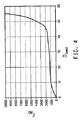
本発明による押出し揺動バンパーを、上述した熱可塑性エラストマーを用いて、表1に記載した設計により作製した。平均壁厚は2.2mmであった。以下の手順を用いて試験した。揺動バンパーを、引張−圧縮機の2つの板の間に置いた。試料を23℃、50mm/分の定速で圧縮した。10kNの上部荷重レベルは、サスペンションの極端な変位の間に揺動バンパーにかかる典型的な力に対応する。力対偏位の変動を測定した。測定された圧縮曲線を図4に示す。曲線の形状が、揺動バンパーに求められる性能を示している。 An extruded rocking bumper according to the present invention was produced by the design described in Table 1 using the thermoplastic elastomer described above. The average wall thickness was 2.2 mm. The following procedure was used for testing. A rocking bumper was placed between the two plates of the tension-compressor. The sample was compressed at 23 ° C. and a constant speed of 50 mm / min. An upper load level of 10 kN corresponds to the typical force applied to the rocking bumper during extreme displacement of the suspension. The variation of force versus deflection was measured. The measured compression curve is shown in FIG. The shape of the curve indicates the performance required for the swing bumper.
Claims (18)
b)熱成形可能な状態にある前記プラスチック材料を、押出しヘッドのピンおよびダイを通して押出して、中空連続管を形成する工程と、
c)前記中空連続管をコルゲート加工する工程と、
d)鎖状につながった多数の揺動バンパーを切断して、単一の不連続な揺動バンパーを形成する工程と
を含む揺動バンパーを製造する方法。 a) supplying molten plastic material to an extruder;
b) extruding the plastic material in a thermoformable state through pins and dies of an extrusion head to form a hollow continuous tube;
c) corrugating the hollow continuous tube;
d) cutting a large number of swing bumpers connected in a chain to form a single discontinuous swing bumper, and manufacturing a swing bumper.
Applications Claiming Priority (2)
| Application Number | Priority Date | Filing Date | Title |
|---|---|---|---|
| US92706207P | 2007-05-01 | 2007-05-01 | |
| PCT/US2008/005618 WO2008137029A2 (en) | 2007-05-01 | 2008-05-01 | Jounce bumpers made by corrugated extrusio |
Publications (2)
| Publication Number | Publication Date |
|---|---|
| JP2010526261A true JP2010526261A (en) | 2010-07-29 |
| JP2010526261A5 JP2010526261A5 (en) | 2011-06-23 |
Family
ID=39719262
Family Applications (1)
| Application Number | Title | Priority Date | Filing Date |
|---|---|---|---|
| JP2010506319A Pending JP2010526261A (en) | 2007-05-01 | 2008-05-01 | Swing bumper made by corrugated extrusion |
Country Status (5)
| Country | Link |
|---|---|
| US (2) | US20080272529A1 (en) |
| EP (1) | EP2142820A2 (en) |
| JP (1) | JP2010526261A (en) |
| CN (1) | CN101675265A (en) |
| WO (1) | WO2008137029A2 (en) |
Cited By (6)
| Publication number | Priority date | Publication date | Assignee | Title |
|---|---|---|---|---|
| KR20130093620A (en) * | 2010-08-12 | 2013-08-22 | 이 아이 듀폰 디 네모아 앤드 캄파니 | Thermoplastic jounce bumpers |
| KR20130093621A (en) * | 2010-08-12 | 2013-08-22 | 이 아이 듀폰 디 네모아 앤드 캄파니 | Thermoplastic jounce bumpers |
| JP2013185708A (en) * | 2012-03-06 | 2013-09-19 | Hyundai Motor Co Ltd | Spring of suspension for vehicle |
| JP2016500142A (en) * | 2012-10-02 | 2016-01-07 | ビーエーエスエフ ソシエタス・ヨーロピアBasf Se | Damper |
| JP2016503866A (en) * | 2012-12-31 | 2016-02-08 | ビーエーエスエフ ソシエタス・ヨーロピアBasf Se | Jounce bumper assembly |
| US10731722B2 (en) | 2015-02-18 | 2020-08-04 | E. I. Du Pont De Nemours And Company | Jounce bumper |
Families Citing this family (14)
| Publication number | Priority date | Publication date | Assignee | Title |
|---|---|---|---|---|
| CN102076989A (en) * | 2008-06-26 | 2011-05-25 | 富国股份有限公司 | Bump stopper and manufacturing method therefor |
| AU2009302629A1 (en) * | 2008-10-09 | 2010-04-15 | Technology From Ideas Limited | Wave energy conversion device |
| US20100101692A1 (en) * | 2008-10-29 | 2010-04-29 | International Marketing, Inc. | Composition for correting force variations and vibrations of a tire-wheel assembly |
| US20100175798A1 (en) * | 2008-10-29 | 2010-07-15 | International Marketing, Inc. | Composition for correcting tire-wheel imbalances, force variations, and vibrations |
| KR101293962B1 (en) * | 2011-11-23 | 2013-08-08 | 기아자동차주식회사 | Plastic composites spring for suspension, device and method for manufacturing the same |
| US20130161888A1 (en) * | 2011-12-21 | 2013-06-27 | E I Du Pont De Nemours And Company | Jounce bumper |
| JP6207310B2 (en) * | 2013-09-12 | 2017-10-04 | 住友理工株式会社 | Dust cover |
| US9394962B2 (en) * | 2013-09-12 | 2016-07-19 | Sumitomo Riko Company Limited | Dust cover |
| JP2017502868A (en) * | 2013-11-24 | 2017-01-26 | メイア,イラン ベン | New wheel and production method |
| KR101551061B1 (en) | 2014-02-17 | 2015-09-07 | 현대자동차주식회사 | Bumper stopper united with dust cover |
| US9988529B2 (en) | 2015-11-20 | 2018-06-05 | Ticona Llc | High flow polyaryletherketone composition |
| US9731670B2 (en) | 2016-01-12 | 2017-08-15 | Ford Global Technologies, Llc | Sequentially buckling vehicle crush can |
| CN106246780B (en) * | 2016-08-31 | 2019-04-16 | 浙江双友物流器械股份有限公司 | A kind of constant force spring |
| GB2568764A (en) * | 2017-11-28 | 2019-05-29 | Airbus Operations Gmbh | Curable composite bush |
Citations (6)
| Publication number | Priority date | Publication date | Assignee | Title |
|---|---|---|---|---|
| JP2000104781A (en) * | 1998-09-29 | 2000-04-11 | Bridgestone Corp | Vibration control device |
| JP2002096372A (en) * | 2000-09-22 | 2002-04-02 | Sekisui Chem Co Ltd | Liner pipe and method for manufacturing it |
| JP2004232673A (en) * | 2003-01-28 | 2004-08-19 | Kubota Corp | Insertion pipe and its manufacturing method |
| JP2006144807A (en) * | 2004-11-16 | 2006-06-08 | Kayaba Ind Co Ltd | Shock absorber |
| JP2006257245A (en) * | 2005-03-16 | 2006-09-28 | Kaneka Corp | Resin magnet composition |
| JP2007078152A (en) * | 2005-09-16 | 2007-03-29 | Nissin Kogyo Co Ltd | Mount rubber |
Family Cites Families (22)
| Publication number | Priority date | Publication date | Assignee | Title |
|---|---|---|---|---|
| US2770841A (en) * | 1952-09-04 | 1956-11-20 | Crown Cork & Seal Co | Method of continuous vulcanizing of rubber |
| US3995901A (en) * | 1974-06-24 | 1976-12-07 | E. I. Dupont De Nemours And Company | Energy-absorbing systems |
| US4073858A (en) * | 1975-04-07 | 1978-02-14 | The Goodyear Tire & Rubber Company | Shock absorbing unit molded from polyurethane (urea) rubber composition |
| US4235427A (en) * | 1979-05-07 | 1980-11-25 | Walter Bialobrzeski | Spring |
| US4402898A (en) * | 1981-09-28 | 1983-09-06 | Hancor, Inc. | Coextrusion die assembly |
| US4424834A (en) * | 1982-09-22 | 1984-01-10 | Kyoraku Co., Ltd. | Elastic shaped article |
| US4712104A (en) * | 1985-04-19 | 1987-12-08 | Kuron Kabushiki Kaisha | Remote control blind system |
| US4962916A (en) * | 1989-11-17 | 1990-10-16 | Uniroyal Chemical Company, Inc. | Compression spring |
| US5192057A (en) | 1991-08-12 | 1993-03-09 | Miner Enterprises, Inc. | Elastomer rebound, jounce and related compression springs |
| US5511965A (en) * | 1991-10-11 | 1996-04-30 | Specialty Silicone Fabricators, Inc. | Apparatus for extruding tubing having a variable outer diameter |
| EP0617769A4 (en) * | 1991-12-23 | 1995-02-08 | Miner Enterprises | Elastomer bumper spring. |
| CA2153009C (en) * | 1994-07-07 | 2007-05-08 | Gary D. Grabaum | Constant velocity joint boot and method of making the same |
| EP0734835B1 (en) | 1995-03-28 | 1999-02-10 | Corelco | Vacuum supply circuit for a plant to produce corrugated tubes |
| DE19700916A1 (en) * | 1997-01-14 | 1998-07-16 | Ralph Peter Dr Ing Hegler | One-piece corrugated corrugated pipe and process for its manufacture |
| US5868384A (en) * | 1997-04-11 | 1999-02-09 | Miner Enterprises, Inc. | Composite elastomeric spring |
| ATE203950T1 (en) | 1997-10-15 | 2001-08-15 | Corelco | DEVICE FOR PRODUCING TUBE-LIKE PLASTIC OBJECTS USING VACUUM |
| US6764627B2 (en) * | 2000-03-23 | 2004-07-20 | Hahn Elastomer Corporation | Method of making corrugated part |
| US6719279B1 (en) * | 2002-08-21 | 2004-04-13 | Bfs Diversified Products, Llc | Air spring sleeve |
| WO2004029155A2 (en) | 2002-09-30 | 2004-04-08 | E.I. Du Pont De Nemours And Company | Curable thermoplastic elastomeric blend, method of manufacture, and use thereof |
| EP1486696A1 (en) * | 2003-06-11 | 2004-12-15 | DSM IP Assets B.V. | Process for making a compression spring member from copolyetherester |
| US20050230891A1 (en) * | 2004-04-14 | 2005-10-20 | Griffin Gary J | Jounce bumper |
| US20060001205A1 (en) * | 2004-06-30 | 2006-01-05 | Irfan Raza | Jounce bumper |
-
2008
- 2008-05-01 CN CN200880013636A patent/CN101675265A/en active Pending
- 2008-05-01 JP JP2010506319A patent/JP2010526261A/en active Pending
- 2008-05-01 US US12/150,833 patent/US20080272529A1/en not_active Abandoned
- 2008-05-01 EP EP08767480A patent/EP2142820A2/en not_active Withdrawn
- 2008-05-01 WO PCT/US2008/005618 patent/WO2008137029A2/en active Application Filing
-
2012
- 2012-01-12 US US13/349,067 patent/US20120104672A1/en not_active Abandoned
Patent Citations (6)
| Publication number | Priority date | Publication date | Assignee | Title |
|---|---|---|---|---|
| JP2000104781A (en) * | 1998-09-29 | 2000-04-11 | Bridgestone Corp | Vibration control device |
| JP2002096372A (en) * | 2000-09-22 | 2002-04-02 | Sekisui Chem Co Ltd | Liner pipe and method for manufacturing it |
| JP2004232673A (en) * | 2003-01-28 | 2004-08-19 | Kubota Corp | Insertion pipe and its manufacturing method |
| JP2006144807A (en) * | 2004-11-16 | 2006-06-08 | Kayaba Ind Co Ltd | Shock absorber |
| JP2006257245A (en) * | 2005-03-16 | 2006-09-28 | Kaneka Corp | Resin magnet composition |
| JP2007078152A (en) * | 2005-09-16 | 2007-03-29 | Nissin Kogyo Co Ltd | Mount rubber |
Cited By (14)
| Publication number | Priority date | Publication date | Assignee | Title |
|---|---|---|---|---|
| KR101914310B1 (en) * | 2010-08-12 | 2018-11-01 | 이 아이 듀폰 디 네모아 앤드 캄파니 | Thermoplastic jounce bumpers |
| KR20130093621A (en) * | 2010-08-12 | 2013-08-22 | 이 아이 듀폰 디 네모아 앤드 캄파니 | Thermoplastic jounce bumpers |
| JP2013536380A (en) * | 2010-08-12 | 2013-09-19 | イー・アイ・デュポン・ドウ・ヌムール・アンド・カンパニー | Thermoplastic rocking bumper |
| JP2013540955A (en) * | 2010-08-12 | 2013-11-07 | イー・アイ・デュポン・ドウ・ヌムール・アンド・カンパニー | Thermoplastic rocking bumper |
| US10737543B2 (en) | 2010-08-12 | 2020-08-11 | Dupont Polymers, Inc. | Thermoplastic jounce bumpers |
| KR101924654B1 (en) * | 2010-08-12 | 2018-12-03 | 이 아이 듀폰 디 네모아 앤드 캄파니 | Thermoplastic jounce bumpers |
| JP2016223632A (en) * | 2010-08-12 | 2016-12-28 | イー・アイ・デュポン・ドウ・ヌムール・アンド・カンパニーE.I.Du Pont De Nemours And Company | Thermoplastic jounce bumpers |
| JP2017015263A (en) * | 2010-08-12 | 2017-01-19 | イー・アイ・デュポン・ドウ・ヌムール・アンド・カンパニーE.I.Du Pont De Nemours And Company | Thermoplastic oscillation bumper |
| KR20130093620A (en) * | 2010-08-12 | 2013-08-22 | 이 아이 듀폰 디 네모아 앤드 캄파니 | Thermoplastic jounce bumpers |
| JP2013185708A (en) * | 2012-03-06 | 2013-09-19 | Hyundai Motor Co Ltd | Spring of suspension for vehicle |
| US9764612B2 (en) | 2012-10-02 | 2017-09-19 | Basf Se | Damper |
| JP2016500142A (en) * | 2012-10-02 | 2016-01-07 | ビーエーエスエフ ソシエタス・ヨーロピアBasf Se | Damper |
| JP2016503866A (en) * | 2012-12-31 | 2016-02-08 | ビーエーエスエフ ソシエタス・ヨーロピアBasf Se | Jounce bumper assembly |
| US10731722B2 (en) | 2015-02-18 | 2020-08-04 | E. I. Du Pont De Nemours And Company | Jounce bumper |
Also Published As
| Publication number | Publication date |
|---|---|
| US20080272529A1 (en) | 2008-11-06 |
| WO2008137029A3 (en) | 2009-09-24 |
| CN101675265A (en) | 2010-03-17 |
| US20120104672A1 (en) | 2012-05-03 |
| EP2142820A2 (en) | 2010-01-13 |
| WO2008137029A2 (en) | 2008-11-13 |
| WO2008137029A4 (en) | 2009-11-12 |
Similar Documents
| Publication | Publication Date | Title |
|---|---|---|
| JP2010526261A (en) | Swing bumper made by corrugated extrusion | |
| US10737543B2 (en) | Thermoplastic jounce bumpers | |
| JP6348552B2 (en) | Thermoplastic rocking bumper | |
| US20090256370A1 (en) | Bumper energy absorbers for pedestrian safety | |
| KR101551061B1 (en) | Bumper stopper united with dust cover | |
| TWI783864B (en) | Damping pad with low compression set | |
| US20130320590A1 (en) | Method for treating thermoplastic jounce bumpers | |
| TWM633919U (en) | Damping pad with low compression set | |
| CN111425545A (en) | Film-coated buffering stop block and preparation method thereof | |
| CN115490908A (en) | Low permanent compression deformation shock pad |
Legal Events
| Date | Code | Title | Description |
|---|---|---|---|
| A521 | Written amendment |
Free format text: JAPANESE INTERMEDIATE CODE: A523 Effective date: 20110426 |
|
| A621 | Written request for application examination |
Free format text: JAPANESE INTERMEDIATE CODE: A621 Effective date: 20110426 |
|
| A977 | Report on retrieval |
Free format text: JAPANESE INTERMEDIATE CODE: A971007 Effective date: 20120920 |
|
| A131 | Notification of reasons for refusal |
Free format text: JAPANESE INTERMEDIATE CODE: A131 Effective date: 20120921 |
|
| A02 | Decision of refusal |
Free format text: JAPANESE INTERMEDIATE CODE: A02 Effective date: 20130308 |