JP2010525548A - Multiple battery polarity protection - Google Patents
Multiple battery polarity protection Download PDFInfo
- Publication number
- JP2010525548A JP2010525548A JP2010506361A JP2010506361A JP2010525548A JP 2010525548 A JP2010525548 A JP 2010525548A JP 2010506361 A JP2010506361 A JP 2010506361A JP 2010506361 A JP2010506361 A JP 2010506361A JP 2010525548 A JP2010525548 A JP 2010525548A
- Authority
- JP
- Japan
- Prior art keywords
- battery
- contact
- dual
- dual contact
- positive
- Prior art date
- Legal status (The legal status is an assumption and is not a legal conclusion. Google has not performed a legal analysis and makes no representation as to the accuracy of the status listed.)
- Granted
Links
- 230000009977 dual effect Effects 0.000 claims abstract description 171
- 230000000712 assembly Effects 0.000 claims abstract description 59
- 238000000429 assembly Methods 0.000 claims abstract description 59
- 239000000758 substrate Substances 0.000 claims abstract description 21
- 239000012212 insulator Substances 0.000 claims description 23
- 230000007246 mechanism Effects 0.000 claims description 6
- 238000001746 injection moulding Methods 0.000 claims description 3
- 230000002093 peripheral effect Effects 0.000 claims description 3
- 230000035515 penetration Effects 0.000 claims description 2
- 125000006850 spacer group Chemical group 0.000 claims description 2
- 238000003466 welding Methods 0.000 claims description 2
- 238000004026 adhesive bonding Methods 0.000 claims 1
- 230000008901 benefit Effects 0.000 description 13
- 239000004033 plastic Substances 0.000 description 8
- 239000000463 material Substances 0.000 description 3
- 238000002347 injection Methods 0.000 description 2
- 239000007924 injection Substances 0.000 description 2
- 238000003780 insertion Methods 0.000 description 2
- 230000037431 insertion Effects 0.000 description 2
- 230000014759 maintenance of location Effects 0.000 description 2
- 239000002184 metal Substances 0.000 description 2
- 239000002991 molded plastic Substances 0.000 description 2
- 239000002253 acid Substances 0.000 description 1
- 230000008878 coupling Effects 0.000 description 1
- 238000010168 coupling process Methods 0.000 description 1
- 238000005859 coupling reaction Methods 0.000 description 1
- 238000010586 diagram Methods 0.000 description 1
- 230000006870 function Effects 0.000 description 1
- 238000009434 installation Methods 0.000 description 1
- 238000009940 knitting Methods 0.000 description 1
- 238000004519 manufacturing process Methods 0.000 description 1
- 239000000615 nonconductor Substances 0.000 description 1
- 238000003825 pressing Methods 0.000 description 1
- 238000000926 separation method Methods 0.000 description 1
- 230000035939 shock Effects 0.000 description 1
- 230000003068 static effect Effects 0.000 description 1
Images


Classifications
-
- H—ELECTRICITY
- H01—ELECTRIC ELEMENTS
- H01M—PROCESSES OR MEANS, e.g. BATTERIES, FOR THE DIRECT CONVERSION OF CHEMICAL ENERGY INTO ELECTRICAL ENERGY
- H01M50/00—Constructional details or processes of manufacture of the non-active parts of electrochemical cells other than fuel cells, e.g. hybrid cells
- H01M50/20—Mountings; Secondary casings or frames; Racks, modules or packs; Suspension devices; Shock absorbers; Transport or carrying devices; Holders
-
- H—ELECTRICITY
- H01—ELECTRIC ELEMENTS
- H01M—PROCESSES OR MEANS, e.g. BATTERIES, FOR THE DIRECT CONVERSION OF CHEMICAL ENERGY INTO ELECTRICAL ENERGY
- H01M50/00—Constructional details or processes of manufacture of the non-active parts of electrochemical cells other than fuel cells, e.g. hybrid cells
- H01M50/50—Current conducting connections for cells or batteries
- H01M50/572—Means for preventing undesired use or discharge
- H01M50/584—Means for preventing undesired use or discharge for preventing incorrect connections inside or outside the batteries
- H01M50/59—Means for preventing undesired use or discharge for preventing incorrect connections inside or outside the batteries characterised by the protection means
- H01M50/597—Protection against reversal of polarity
-
- H—ELECTRICITY
- H01—ELECTRIC ELEMENTS
- H01M—PROCESSES OR MEANS, e.g. BATTERIES, FOR THE DIRECT CONVERSION OF CHEMICAL ENERGY INTO ELECTRICAL ENERGY
- H01M50/00—Constructional details or processes of manufacture of the non-active parts of electrochemical cells other than fuel cells, e.g. hybrid cells
- H01M50/50—Current conducting connections for cells or batteries
- H01M50/502—Interconnectors for connecting terminals of adjacent batteries; Interconnectors for connecting cells outside a battery casing
- H01M50/509—Interconnectors for connecting terminals of adjacent batteries; Interconnectors for connecting cells outside a battery casing characterised by the type of connection, e.g. mixed connections
- H01M50/512—Connection only in parallel
-
- H—ELECTRICITY
- H01—ELECTRIC ELEMENTS
- H01M—PROCESSES OR MEANS, e.g. BATTERIES, FOR THE DIRECT CONVERSION OF CHEMICAL ENERGY INTO ELECTRICAL ENERGY
- H01M50/00—Constructional details or processes of manufacture of the non-active parts of electrochemical cells other than fuel cells, e.g. hybrid cells
- H01M50/50—Current conducting connections for cells or batteries
- H01M50/543—Terminals
-
- Y—GENERAL TAGGING OF NEW TECHNOLOGICAL DEVELOPMENTS; GENERAL TAGGING OF CROSS-SECTIONAL TECHNOLOGIES SPANNING OVER SEVERAL SECTIONS OF THE IPC; TECHNICAL SUBJECTS COVERED BY FORMER USPC CROSS-REFERENCE ART COLLECTIONS [XRACs] AND DIGESTS
- Y02—TECHNOLOGIES OR APPLICATIONS FOR MITIGATION OR ADAPTATION AGAINST CLIMATE CHANGE
- Y02E—REDUCTION OF GREENHOUSE GAS [GHG] EMISSIONS, RELATED TO ENERGY GENERATION, TRANSMISSION OR DISTRIBUTION
- Y02E60/00—Enabling technologies; Technologies with a potential or indirect contribution to GHG emissions mitigation
- Y02E60/10—Energy storage using batteries
Landscapes
- Chemical & Material Sciences (AREA)
- Chemical Kinetics & Catalysis (AREA)
- Electrochemistry (AREA)
- General Chemical & Material Sciences (AREA)
- Battery Mounting, Suspending (AREA)
- Connection Of Batteries Or Terminals (AREA)
Abstract
電池が電池キャリッジに挿入される向きにかかわらず、正しい極性で電池と接続する電池キャリッジが、本明細書において提供される。そのような電池キャリッジは、有利には、電池を使用するあらゆるデバイスと共に使用することができる。そのようなデバイスは、2つ以上の電池キャリッジを含むことができ、電池キャリッジはそれぞれ、基板上に配置される第1のデュアル接点アセンブリ及び第2のデュアル接点アセンブリを含む。2つのデュアル接点アセンブリはそれぞれ、プラスの接点及びマイナスの接点を有することができる。プラスの接点はそれぞれ、電池のプラスの端子に接触すると共にプラスの回路接続部に接続されるように構成されることができ、マイナスの接点はそれぞれ、電池のマイナスの端子に接触すると共にマイナスの回路接続部に接続されるように構成されることができる。 Provided herein is a battery carriage that connects to the battery with the correct polarity regardless of the orientation in which the battery is inserted into the battery carriage. Such a battery carriage can advantageously be used with any device that uses batteries. Such a device can include two or more battery carriages, each of which includes a first dual contact assembly and a second dual contact assembly disposed on a substrate. Each of the two dual contact assemblies can have a positive contact and a negative contact. Each positive contact can be configured to contact the positive terminal of the battery and to be connected to the positive circuit connection, and each negative contact contacts the negative terminal of the battery and is negative. It can be configured to be connected to a circuit connection.
Description
本発明は、複数の電池の極性保護に関する。 The present invention relates to polarity protection for a plurality of batteries.
電池はそれぞれ、通常、このような電池から電力を引き出す電気デバイス又は製品に適切な向きで装着されなくてはならない。適切な装着は、普通、電池受入れエリア付近若しくはそのエリア内の製品上若しくは製品内に、書面の取扱説明を用いることにより、又は図解の使用説明を用いることによって達成され、このような取扱説明又は使用説明により、正しい電気極性について適切な電池の向きが識別される。 Each battery typically must be mounted in an appropriate orientation in an electrical device or product that draws power from such a battery. Proper installation is usually accomplished by using written instructions on or in the product near or in the battery receiving area, or by using the illustrated instructions, such instructions or The instructions for use identify the proper battery orientation for the correct electrical polarity.
ユーザーは、このような取扱説明に正確に従うことが多いが、時に図解が製品の筺体の中に又はその筺体の一部として直接成形されるか、又は使用説明が、ますます小さいラベルになっていくように思われることがあるものの上に印刷されたりする場合があるため、図解を理解するのが困難な場合がある。さらに、電池は時に、単にユーザーの誤りに起因して誤って挿入されることが避けられない。その結果、電池の問題及び製品の損傷が生じる場合がある。電池が電子製品内で誤った極性に方向付けられると、最良の場合でも製品が適切に電力を引き出すことができなくて単に動作しないことがあり得る。もっと悪い場合では、電池が過熱する、且つ/又は腐食性の酸が漏れる可能性があり、それによって、電子機器に永久的な損傷が生じる、製品を破壊する、出火若しくは破裂が生じる、且つ/又はユーザーに怪我をさせる可能性がある。したがって、誤った向きで装着された電池に伴うリスクが、絶えざる実質的な問題を提示する。 Users often follow these instructions exactly, but sometimes the illustrations are molded directly into or as part of the product housing, or the instructions for use become increasingly smaller labels. It may be difficult to understand the illustration because it may be printed on what may seem to be. In addition, batteries are sometimes unavoidably inserted simply due to user error. As a result, battery problems and product damage may occur. If the battery is oriented in the wrong polarity within the electronic product, even in the best case it may not be possible for the product to properly draw power and simply operate. In worse cases, the battery may overheat and / or leak corrosive acid, thereby causing permanent damage to the electronics, destroying the product, causing fire or rupture, and / or Or it may injure the user. Thus, the risks associated with batteries installed in the wrong orientation present a constant and substantial problem.
上記の議論は、単に一般的な背景技術情報のために提供され、特許請求される主題の範囲の決定を補助するものとして用いられることは意図されていない。 The above discussion is provided merely for general background information and is not intended to be used as an aid in determining the scope of the claimed subject matter.
電池が電池キャリッジ(carriages)に挿入される向きにかかわらず、正しい極性で電池と接続する電池キャリッジが、本明細書において提供される。そのような電池キャリッジは、有利なことに、電池を使用するあらゆるデバイスと共に使用することができる。そのようなデバイスは、2つ以上の電池キャリッジを含むことができ、電池キャリッジはそれぞれ、基板上に配置される第1のデュアル接点(dual-contact)アセンブリ及び第2のデュアル接点アセンブリを含む。2つのデュアル接点アセンブリはそれぞれ、プラスの接点及びマイナスの接点を有してもよい。プラスの接点はそれぞれ、電池のプラスの端子に接触すると共にプラスの回路接続部に接続されるように構成されることができ、マイナスの接点はそれぞれ、電池のマイナスの端子に接触すると共にマイナスの回路接続部に接続するように構成されることができる。 Provided herein is a battery carriage that connects with the battery with the correct polarity regardless of the orientation in which the battery is inserted into the battery carriage. Such a battery carriage can advantageously be used with any device that uses batteries. Such a device can include two or more battery carriages, each including a first dual-contact assembly and a second dual contact assembly disposed on the substrate. Each of the two dual contact assemblies may have a positive contact and a negative contact. Each positive contact can be configured to contact the positive terminal of the battery and to be connected to the positive circuit connection, and each negative contact contacts the negative terminal of the battery and is negative. It can be configured to connect to a circuit connection.
この概要は、詳細な説明において以下にさらに説明される概念のいくつかを単純化された形式で紹介するために提供される。この概要は、特許請求される主題の重要な又は本質的な特徴を特定するように意図されているものではなく、また、特許請求される主題の範囲の決定を補助するものとして用いられることを意図されているものでもない。特許請求される主題は、背景技術に記される任意の又は全ての不利な点を解決する実施態様に限定されない。 This summary is provided to introduce a selection of concepts in a simplified form that are further described below in the Detailed Description. This summary is not intended to identify key or essential features of the claimed subject matter, nor is it intended to be used as an aid in determining the scope of the claimed subject matter. It is not intended. The claimed subject matter is not limited to implementations that solve any or all disadvantages noted in the background art.
図1は、例示的な一実施形態による、複数電池キャリッジ100を示す。複数電池キャリッジ100は、各電池を特定の向きで配置することを必要とし、この条件が満たされないと機能不全を起こす従来のデバイスとは対照的に、電池を、いずれの向きのセットにおいても1つのデバイスと接続して配置することができると共に効果的に使用することができるようにするデバイスの例示的な一実施形態である。複数電池キャリッジ100は、様々な実施形態において、計算システム、電子デバイス、及び電池を使用するあらゆる装置等の実施形態に含まれ得る。以下の論考は、そのような様々な実施形態の特定の例示的な例のさらなる詳細を提供する。特定の例示的な複数電池キャリッジがこの図及び後続の図に含まれるが、これらは、一切の限定を示さないように意図されており、むしろ、様々な例示的な態様並びに、本願における明細書及び特許請求の範囲に提供されるより広範な意味を示すように意図されている。
FIG. 1 illustrates a
複数電池キャリッジ100は、第1の電池キャリッジ111及び第2の電池キャリッジ113を含む。第1の電池キャリッジ111は、基板115とデュアル接点アセンブリ121及び123とを含み、その一方で第2の電池キャリッジ113は、基板115とデュアル接点アセンブリ125及び127とを含む。デュアル接点アセンブリ121は、絶縁体131とプラスの接点133とマイナスの接点135とを含み;デュアル接点アセンブリ123は、絶縁体141とプラスの接点143とマイナスの接点145とを含む。デュアル接点アセンブリ125は、絶縁体141とプラスの接点147とマイナスの接点149とを含み;デュアル接点アセンブリ127は、絶縁体151とプラスの接点153とマイナスの接点155とを含む。デュアル接点アセンブリ123及び125はいずれも、両面(double-sided)デュアル接点アセンブリ119を共に構成しており、共通した構成要素の1つ、すなわち絶縁体141を共有する。両面デュアル接点アセンブリ119は、周辺のデュアル接点アセンブリ121及び127の中間に配置されている。
The
デュアル接点アセンブリ121は、ばねで留められた(spring-loaded)デュアル接点特徴部133及び161を含み、デュアル接点アセンブリ127は、ばねで留められたデュアル接点特徴部153及び167を含む。これらのばねで留められたデュアル接点特徴部は、この例示的な実施形態において、それぞれの電池キャリッジに配置される電池が、それぞれの電池キャリッジのいずれかの端にあるデュアル接点特徴部間に弾性的に且つぴったりと受け入れられ、両側にあるデュアル接点特徴部との継続的接触を維持することを保証するのを助ける。他の実施形態では、両面デュアル接点アセンブリは、そのいずれも面にもばねで留められたデュアル接点アセンブリを有してもよいし、又はばねで留められたデュアル接点アセンブリの他の組合せ及び構成を有する2つ以上の電池キャリッジを有してもよい。さらに他の実施形態は、ばねで留められたデュアル接点アセンブリを一切有しないで構成される場合もあるが、ばねで留められたデュアル接点アセンブリを有しない電池キャリッジに配置される電池との確実な接続を維持するように構成され得る。
さらに詳細に以下で説明するように、プラスの接点133、143、147及び153はそれぞれ、電池のプラスの端子に接触すると共にプラスの回路接続部に接続されるように構成され、マイナスの接点135、145、149及び155はそれぞれ、電池のマイナスの端子に接触すると共にマイナスの回路接続部に接続されるように構成される。例えばデュアル接点アセンブリ127に関して分かるように、プラスの接点153は、その端が接点171を形成するように基板115を貫通するタブを有し、その一方でマイナスの接点155の2つのタブが、接点173及び175として基板115を貫通する。他のデュアル接点アセンブリ121、123及び125も、各々のプラスの接点及びマイナスの接点に関して基板115を貫通する接点を有するが、これらは図1には見られない。基板115は、プリント回路基板(PCB)の形態をとることができ、例えば、デュアル接点アセンブリの接点のいくつかの部分が適切な極性の回路接続部を導電接触させることができる、挿入開口部を有することができる。回路接続部は、例えばタブの突起部分又は基板内の接続部を介して外部接続することができる。
As described in more detail below, the
図2は、電池キャリッジ111、113それぞれに配置される電池191、193を有する複数電池キャリッジ100を示す。電池191、193は、AA若しくはAAAサイズの電池の一般的な形態で示されているが、異なる複数電池キャリッジデバイスを、任意の異なるサイズ及び種類の電池、例えばC若しくはDサイズの電池、又は例示的には標準的な9ボルト電池のような、プラスの接点及びマイナスの接点に関して異なる構成若しくは形態を有する電池を受け入れるように構成することもできる。他の実施形態では、プラスの及びマイナスの端子並びに接点を逆にしてもよく、これに従って、例えば、これらの実施形態下での電池キャリッジデバイスは、それぞれがプラスの接点又はマイナスの接点として構成され得る、中央且つ後方に位置決めされる接点と、半径方向外方且つ前方に位置決めされる環状の接点とを有して構成されてもよいし、又は様々な例示的な実施形態において任意の種類の電池の端子の位置決めと一致させるという必要に応じて他の任意の構成で構成されてもよい。図2において分かるように、ばねで留められたデュアル接点特徴部161及び167並びにばねで留められたプラスの接点133及びに153は、電池191及び193を配置することによってそれぞれ反射的に変形され、その結果、ばねで留められたデュアル接点特徴部161及び167が電池191及び193に対して押圧して電池191及び193との継続的接続を保証するのを助ける。したがって、電池191は、デュアル接点アセンブリ121と両面デュアル接点アセンブリ119との間で押圧され、電池193は、両面デュアル接点アセンブリ119とデュアル接点アセンブリ127との間で押圧される。電池の向きにかかわらず電池から適切な電荷極性を引き出す際のデュアル接点アセンブリの例示的な利点が、図3により明確に示されている。図2は、図3の電池キャリッジ111の断面図と見比べるための基準フレームを提供する線4−4を含む。
FIG. 2 shows a
図3は、トップダウン平面図における電池キャリッジ111を示し、デュアル接点アセンブリ121及び123と電池191のプラスの接点及びマイナスの接点との接触面(interface)をより明確に示す。図3の描写では、電池191は、プラスの端子192がデュアル接点アセンブリ121と接続して配置され且つマイナスの端子194がデュアル接点アセンブリ123(これ自体が両面デュアル接点アセンブリ119の一部を形成する)と接続して配置される状態で、電池キャリッジ111内で方向付けられている。この向きは任意ではあるが、逆向きにしても同様に良好に機能する。
FIG. 3 shows the
図3に示されるように、デュアル接点アセンブリ121のプラスの接点133は、デュアル接点アセンブリ121内で、プラスの接点133が半径方向に内方の且つ軸方向に陥凹している(recessed)位置にあることに本質的に起因して、電池191のプラスの端子192と接触している。すなわち、プラスの接点133は、この例示的な実施形態では、マイナスの接点135の半径方向内方にあり、且つ電池191の位置からデュアル接点アセンブリ及び電池の中心によって画定される軸に沿ってマイナスの接点135に対して離れて陥凹している。さらに、この例示的な実施形態では、絶縁体131が、プラスの端子192及びマイナスの接点135の物理的分離(半径方向及び軸方向を含む)を保証するのを助ける。電池191が、プラスの端子がデュアル接点アセンブリ121と接続して位置合わせされた状態で電池キャリッジ111内に配置されると、電池191のプラスの端子192は、突出した形状のプラスの端子192とデュアル接点アセンブリ121との接触面に起因して、プラスの接点133に接触させられて、マイナスの端子135に接触することを妨げられる。
As shown in FIG. 3, the
同様に、電池191のマイナスの端子194は、マイナスの端子194のより広い、平坦な表面と、プラスの接点143に比べて実質的に環状の、マイナスの接点145の半径方向に取り囲んで軸方向前方に配置される位置との接触面に起因して、デュアル接点アセンブリ123のマイナスの接点145に接触させられて、デュアル接点アセンブリ123のプラスの端子143に接触することを妨げられる。すなわち、この例示的な実施形態では、マイナスの接点145は、プラスの接点143の半径方向外方に配置され、デュアル接点アセンブリ及び電池の中心によって画定される軸に沿って、プラスの接点143に対して電池191の位置へ向かって前方に配置される。
Similarly, the
そのため、電池191は図3において1つの特定の向きで示されているが、それと同じくらい容易に、電池191は電池キャリッジ111内に逆向きに配置しても、同極接触をもたらすことができ、電池のプラスの端子及びマイナスの端子は、電池キャリッジの構成に本質的に起因して、これらの端子をデュアル接点アセンブリに接続する際に適切な接点と接触した状態で自動的に保持され、誤った接点に接触することが自動的に防止される。特に、図3の例示的な例を参照すると、電池191が電池キャリッジ111内に逆向きに配置された場合、電池191のプラスの端子192は、デュアル接点アセンブリ123のプラスの接点143と接触した状態に自動的に配置され、デュアル接点アセンブリ123のマイナスの接点145と接触することが自動的に防止され、その一方で電池191のマイナスの端子194は、デュアル接点アセンブリ121のマイナスの接点135と接触した状態に自動的に配置され、デュアル接点アセンブリ121のプラスの接点133に接触することが自動的に防止される。これと同じことが、電池193と両面デュアル接点アセンブリ119のプラスの接点147に当接する電池193のプラスの端子196とに関する断片的な描写に示されるように、電池キャリッジ113にも当てはまる。同様に、他の実施形態で使用されるさらなる電池キャリッジにも当てはまり得る。図1〜図3の描写は、様々な他の構成においてそのような利点を同様に提供することができる広範囲の電池キャリッジデバイスの例示にすぎない。
As such, the
したがって、ユーザーは、電池を電池キャリッジ内に向きを問わずに配置することができ、電池は常に適切な接点に接続されること、及びデバイスは安全に且つ効果的に必要とされる電力を自動的に引き出すことをユーザーに保証することができる。 Thus, the user can place the battery in any orientation in the battery carriage, the battery will always be connected to the appropriate contacts, and the device will automate the required power safely and effectively. Can be assured to the user.
図3もまた、両面デュアル接点アセンブリ119の利点を示しており、2つの電池(両面デュアル接点アセンブリ119のいずれかの面に対して1つの電池)に対する本質的に適切な接触極性を提供し、構成要素を連結すると共に、別個のデュアル接点アセンブリを有する場合に対して構成を単純化することができる。両面デュアル接点アセンブリ119は、2つのプラスの電池の端子を両面デュアル接点アセンブリ119のいずれの面にも接触させるか、2つのマイナスの電池の端子を両面デュアル接点アセンブリ119のいずれの面にも接触させるか、又は1つのプラスの端子を両面デュアル接点アセンブリ119の一方の面に接触させ、1つのマイナスの端子を両面デュアル接点アセンブリ119の他方の面に接触させるように、2つの電池を任意の組合せの向きでそのいずれの面にも配置させることができ、また両面デュアル接点アセンブリ119は、端子のそれぞれが、両面デュアル接点アセンブリ119の対応する接点に、したがって適切な極性の回路接続部にも自動的に接続されることが保証される。
FIG. 3 also illustrates the advantages of double-sided
したがって、両面デュアル接点アセンブリ119は、電池キャリッジの回路接続部に対する損傷を与える可能性がある誤った極性に配置されている電池に対して耐性があるという点で耐極性(polarity-proof:両極対応)電池接点アセンブリとしての役割を果たす。電池が、隣接した一対のデュアル接点アセンブリの間、例えばデュアル接点アセンブリ121及び123の間又はデュアル接点アセンブリ125及び127の間に配置されると、電池の端子がその隣接した一対のデュアル接点アセンブリに対していずれの向きに方向付けられているかにかかわらず、電池のプラスの端子はプラスの回路接続部と導電接続され、電池のマイナスの端子はマイナスの回路接続部と導電接続される。
Thus, the dual-sided
図1及び図2の実施形態は、2つの電池キャリッジを軸方向に隣接した構成で有するデバイスを示しているが、これらは多種多様なさらなる構成の例示にすぎず、隣接した複数対の電池キャリッジで構成される、3つ、4つ、又は任意の数の電池キャリッジを含んでもよく、この場合、デバイスに備わっている隣接したデュアル接点アセンブリの任意の又は全ての接触面で、複数のデュアル接点アセンブリを統合して連結されたデュアル接点アセンブリにまとめることができる。さらに、両面デュアル接点アセンブリ119は、共通した絶縁体141を共有するように図1〜図3に示されているが、他のデュアル接点アセンブリもまた、共通した他の構成要素を共有するか又は様々なデュアル接点アセンブリのための他の構成要素を、プラスの接点及びマイナスの接点のような単一の構成要素から形成することによって、連結の利点を実現することができる。
Although the embodiment of FIGS. 1 and 2 shows a device having two battery carriages in an axially adjacent configuration, these are merely examples of a wide variety of additional configurations, and adjacent pairs of battery carriages. May comprise three, four, or any number of battery carriages, in which case a plurality of dual contacts at any or all contact surfaces of adjacent dual contact assemblies provided in the device Assemblies can be combined into a connected dual contact assembly. In addition, although the double-sided
図4は、図1の複数電池キャリッジ100と同様であるが、一連の電池キャリッジの両端点のデュアル接点アセンブリ421、429に加えて、2つではなく3つの電池キャリッジ411、413、415と、1つではなく2つの両面デュアル接点アセンブリ417、419とを有する複数電池キャリッジ401を含むコンピュータキーボード400の裏面を示す。図4に示されるように、両面デュアル接点アセンブリ419は、一方の面に固定式(static)デュアル接点アセンブリ、及び他方の面にばねで留められたデュアル接点アセンブリを有し、その一方で両面デュアル接点アセンブリ417は、両側に固定式デュアル接点アセンブリを有する。これによって、この一連の両端点におけるばねで留められた接点であるデュアル接点アセンブリ421、429と共に、各電池が、1つのばねで留められたデュアル接点アセンブリと接触して、弾性的に掴まれて嵌まった状態のままにあることを助けること、したがって、端子は接触表面と確実に接触したままであることが保証される。コンピュータキーボード400は、有利には複数電池キャリッジを利用することができる電源付きデバイスの1つの例示的な例である。任意の電池式のデバイスを含む多種多様な他のデバイスもまた、本明細書に記載されるような複数電池キャリッジデバイスから利益を得ることができ、コンピュータキーボード400の特定の例は、様々な他の実施形態に対する限定を一切意味しない。電池491、493、495は、電池キャリッジ411、413、415内に配置されて示されている。他の実施形態では、任意の数の電池キャリッジを複数電池キャリッジの編成(grouping)に含めてもよく、2つの隣接した電池キャリッジ間の各接触面は、2つの電池キャリッジのそれぞれにおいて別個で単独のデュアル接点接触面を有することに比べて利点を提供する、組み合わせられたデュアル接点接触面を備えることができる。コンピュータキーボード400は、デュアル接点アセンブリを有する複数電池キャリッジを備えると共にそれから利益を得ることができる例示的なデバイスの例示的な実施形態として提供されているが、これは、デュアル接点アセンブリを有する複数電池キャリッジの編成から利益を得ることができる多種多様なデバイスからの一例にすぎず、あらゆる電気デバイスを含むことができる。
FIG. 4 is similar to the
図5は、デュアル接点アセンブリの様々な構成を有する複数電池キャリッジデバイスのいくつかの例示的な構成の簡略図を示しており、ばねで留められたものもあれば、固定式の(すなわち、ばね無し又はばねで留められていない)ものもある。電池キャリッジデバイス500は、図1〜図3の構成に対応しており、この場合、デュアル接点デバイス521及び527は、ばねで留められた片面デュアル接点アセンブリであり、電池キャリッジ511及び513間の接触面は、ばね無しの両面デュアル接点アセンブリ519を備える。電池キャリッジデバイス530は、一連の3つの電池キャリッジ541、543、545を含み、一連の電池キャリッジの両外縁にばねで留められた片面デュアル接点アセンブリ551、557と;第1の電池キャリッジ541及び第2の電池キャリッジ543の間に固定式両面デュアル接点アセンブリ553と;第2の電池キャリッジ543及び第3の電池キャリッジ545の間に、ばねで留められた一方の面及び固定式の他方の面を有する両面デュアル接点アセンブリ555とを有する。他の実施形態では、両面固定式アセンブリ553及び片面が固定式で片面がばねで留められたアセンブリ555の位置を交換してもよく、又は、確実な電池の位置決めを保証するのを助ける場合さらなる固定式の面をばねで留められた面と交換してもよく、又は様々な異なる実施形態では、構成における他の変形を含んでもよい。
FIG. 5 shows a simplified diagram of several exemplary configurations of a multiple battery carriage device having various configurations of dual contact assemblies, some of which are spring clamped, fixed (ie, springs). Some are not or are not spring-loaded. The
電池キャリッジデバイス560は、一連の4つの電池キャリッジ571、573、575、577を含み、この一連の電池キャリッジの両外縁にばねで留められた片面デュアル接点アセンブリ581、589と;第1の電池キャリッジ571及び第2の電池キャリッジ573の間に固定式両面デュアル接点アセンブリ583と;第2の電池キャリッジ573及び第3の電池キャリッジ575の間に両面デュアル接点アセンブリ585並びに第3の電池キャリッジ575及び第4の電池キャリッジ577の間に両面デュアル接点アセンブリ587とを有し、この場合、デュアル接点アセンブリ585、587のそれぞれは、片面がばね押し式で片面が固定式である。このように、図5において、電池は全ての異なる電池キャリッジに様々な向きで配置されており、各電池の各端子は、隣接したデュアル接点アセンブリの適切な極性(プラス又はマイナス)を有する接点に接続しており;電池は他の任意の向きのセットでも適切な極性のままである。同様に、様々な他の構成もまた他の実施形態において行うことができ、ここでアセンブリの位置決めを再構成することができ、さらなる固定式アセンブリを、所望の電池の位置決めと一致するようにばねで留められたアセンブリと置き換えることもでき、又はその逆もでき、他の種類の変形も実施可能である。
The
したがって、電池キャリッジデバイス500、530、560のそれぞれは、各デバイスのそれぞれの電池キャリッジに配置される電池に対する弾性的に固定した接続を保証する。電池キャリッジデバイス500、530、及び560は、本明細書に開示されるように異なる種類のデュアル接点アセンブリを使用して作り上げることができるさまざまな構成のうちのいくつかを示す。デュアル接点アセンブリの多種多様な他の構成の任意のものを含む他のデバイスが本開示内に包含されており、これは、図5に示される組合せのようなデュアル接点アセンブリの異なる組合せで推定することができる実施形態内に、任意の組合せで、また任意の数又は構成の電池キャリッジを有するように包含される。
Thus, each of the
図6は、上記の図面のばね無しの両面デュアル接点アセンブリ119、519、553、及び583と同様のばね無しの両面デュアル接点アセンブリ600のより明確な描写を提供している。上記のデュアル接点アセンブリと同様に、デュアル接点アセンブリ600は絶縁体621と、プラスの接点623及び627と、マイナスの接点625及び629とを含む。
FIG. 6 provides a clearer depiction of a springless double-sided
図6は、ばね無しの両面デュアル接点アセンブリの細部、例えば、切り欠き付きタブ又はストッパ付きタブ609の説明を容易にし、切り欠き付きタブ又はストッパ付きタブ609を、図1の基板115のような基板のスロット内に、タブ609にある切り欠き段部の位置によって制御される自己限定的な深さまで埋没させることができる。各切り欠き段部の下方に画定される狭い方のセクションが、基板の取り付け開口部を係合貫通するように構成され、その一方で広い方のストッパセクションが、切り欠き段部の上方に画定され、タブの貫通の深さを制限するように構成される。プラスの接点623、627のそれぞれに接続されるタブはプラスの回路接続部に接続されるように構成され、マイナスの接点625、629のそれぞれと接続されるタブの少なくとも1つは、マイナスの回路接続部に接続されるように構成される。
FIG. 6 facilitates the description of details of a springless double-sided dual contact assembly, for example, a notched tab or a
したがって、これらのストッパ付きタブは、デュアル接点アセンブリ600が基板に対して適切な高さで位置決めされるように用意することを助ける。他の例示的な実施形態では、任意の数のストッパ付きタブ又は類似の機構を含めてもよい。これは、一実施形態において、デュアル接点アセンブリ毎に単一のストッパ付きタブしか含まなくてもよいし、又は、デュアル接点アセンブリの位置決めを確実に維持することに応じて、図6に示されているよりも多くの数のタブを含んでいてもよい。金属接触において形成されるL字型の屈曲、プラスチック絶縁体の延長部、さらなるスペーサ部、又は他の機構若しくは上述したものの組合せのような他の種類の機構によってもアセンブリの適切な高さを保証することができる。
Thus, these tabs with stoppers help to prepare the
さらなる詳細な特徴部は、プラスの接点623の埋め込みウイング632、634とプラスの接点627の埋め込みウイング636、638とを含む。これらのプラスの接点は、電池の端子に接触するのに利用可能である露出エリアよりも広く、その両外縁が絶縁体621に埋め込まれるウイングを形成している。これらの埋め込みウイングは、プラスの接点623、627がデュアル接点アセンブリ600内で適切な位置を永久的に維持することを保証するのを助ける。
Further detailed features include embedded
デュアル接点アセンブリ600の構造上の安定性を保証する役割を果たすさらなる特徴部は、マイナスの接点625を絶縁体621に対して固定するプラスチックステーク(plastic stakes)641、プラスの接点623を絶縁体621に対して固定するプラスチックステーク643、並びにマイナスの接点629及びプラスの接点627を絶縁体621に対して固定する、図6には見えない対応するプラスチックステークである。絶縁体621は、例えば、この例示的な実施形態では、射出成形されたプラスチック又は他の電気的絶縁体料から構成され、次いで導電性構成要素を接合され得る。接点623、625、627、及び629のそれぞれに、プラスチックステークが示されている位置において開口部を形成することができ、絶縁体621の射出成形されたプラスチックは、その開口部を通って突出することができる。プラスチックから成る突出部のそれぞれは次いで、それぞれの開口部の環の回りで半径方向に拡張及び圧縮されて図6に示す形状に整えられるように、加熱されて接点に対して圧縮されることができ、この場合、各プラスチックステークは、それぞれの接点を絶縁体621に対してしっかりと固定する。超音波溶接、金属挿入による射出成形、接着等が挙げられるがこれらに限定されない多種多様な他の特徴及び製造プロセスを使用して、多種多様な実施形態の下で(図6の実施形態は例示にすぎない)、様々なデュアル接点アセンブリの構造的な要素を統合することもできる。
Additional features that serve to ensure the structural stability of the
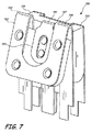
同様の特徴部が図7にも示されており、図7は、プラスの接点723及びマイナスの接点725用のばねで留められた接点を一方の面に有し、且つプラスの接点727及びマイナスの接点729用のばね無しの接点を他方の面に有する両面デュアル接点アセンブリ700を示す。特に、プラスの接点723は、ばねで留められたジョイント751を介して絶縁体721に接続され、マイナスの接点725は、ばねで留められたジョイント753、755を介して絶縁体721に接続される。両面デュアル接点アセンブリ700もまた、図6の両面デュアル接点アセンブリ600のプラスチックステーク及び切り欠き付きタブと同様のプラスチックステーク及び切り欠き付きタブを特徴とする。他の実施形態は、例えば図6に示すような1つのばねで留められた面及び1つの固定式の面を有する両面デュアル接点アセンブリではなく、アセンブリ700の両面にばねで留められたデュアル接点アセンブリを有するように行うこともできる。図5に示すような、電池キャリッジデバイスの両面デュアル接点アセンブリの任意のもの又は全てのものを、別の例示的な例として図7に示す形態で提供してもよい。
Similar features are also shown in FIG. 7, which has spring-loaded contacts for
図8は、電池キャリッジデバイスの他の構成要素と任意に組み合わせて使用することができる両面デュアル接点アセンブリ800のさらに別の例示的な例を提供する。両面デュアル接点アセンブリ800は、直列及び並列の電池接続の可能性に関して背景技術を鑑みると最良に分かるさらなる利点を提供する。
FIG. 8 provides yet another illustrative example of a double-sided
異なる電池キャリッジデバイスでは、直列に又は並列に接続される電池キャリッジの回路接続部を有することが望まれ得る。典型的な、端と端とが接する複数電池キャリッジでは、適切な極性の接続部が回路接続部に導電接続されるように各電池は適切な向きで挿入されなければならないという制約に従うように、回路接続部は直列に配置される。これらの配置はまた、平行な回路接続部を含まない。 In different battery carriage devices, it may be desirable to have battery carriage circuit connections connected in series or in parallel. In a typical end-to-end multi-battery carriage, to obey the constraint that each battery must be inserted in the proper orientation so that the appropriate polarity connection is conductively connected to the circuit connection. The circuit connections are arranged in series. These arrangements also do not include parallel circuit connections.
本明細書に開示される異なる実施形態は、電池の端子のそれぞれにデュアル接点アセンブリが位置しているため、各電池の向きにかかわらず複数の電池キャリッジのそれぞれにおける電池の適切な直列接続又は並列接続を自動的に保証することができる。当業者が容易に理解するように、電池キャリッジによる並列接続は、各デュアル接点アセンブリのプラスの接点と、共通のプラスの接続部との導電接続を提供すること、及び各デュアル接点アセンブリのマイナスの接点と共通のマイナスの接続部との導電接続を提供することによって、自動的に保証されることができ;その一方で電池キャリッジによる直列接続は、各デュアル接点アセンブリのプラスの接点のチェーン接続、及び各デュアル接点アセンブリのマイナスの接点のチェーン接続を提供することによって自動的に保証されることができる。 The different embodiments disclosed herein have a dual contact assembly located at each of the battery terminals so that appropriate series connection or parallel connection of the batteries in each of the plurality of battery carriages regardless of the orientation of each battery. Connection can be guaranteed automatically. As those skilled in the art will readily appreciate, the parallel connection by the battery carriage provides a conductive connection between the positive contact of each dual contact assembly and the common positive connection, and the negative connection of each dual contact assembly. By providing a conductive connection between the contacts and the common negative connection, it can be automatically ensured; while the series connection by the battery carriage, the chain connection of the positive contacts of each dual contact assembly, And can be automatically ensured by providing a chain of negative contacts for each dual contact assembly.
さらに、電池キャリッジデバイスが並列接続用に設計される場合、両面デュアル接点アセンブリのいずれの面にもあるプラスの接点は基板内に接続されることができ、また両面デュアル接点アセンブリのいずれの面にもあるマイナスの接点も基板内に接続されることができる。しかしながら、これらはいずれにしても両面デュアル接点アセンブリの付近で接続されるため、両面アセンブリの両面からの接点を、該アセンブリの対向する面にある対応する接点とこのアセンブリ自体内で組み合わせることができる。これは、1つの例示的な実施形態に従って、図8に示される。 In addition, if the battery carriage device is designed for parallel connection, the positive contacts on either side of the double-sided dual contact assembly can be connected into the board and on either side of the double-sided dual contact assembly Some negative contacts can also be connected in the substrate. However, since they are connected in the vicinity of the double-sided dual contact assembly anyway, contacts from both sides of the double-sided assembly can be combined within the assembly itself with corresponding contacts on opposite sides of the assembly. . This is illustrated in FIG. 8 according to one exemplary embodiment.
図8では、プラスの接点823、827は、両面デュアル接点アセンブリ800の上部にわたる接続ブリッジ832を介して、単一の一体化した構成要素の複数のセクションとして共に接続され、その一方でマイナスの接点825、829もまた、両面デュアル接点アセンブリ800の上部にわたる接続ブリッジ834、836を介して、単一の一体化した構成要素の複数のセクションとして共に接続される。他の実施形態では、異なる実施形態において利用可能な異なる構成の多くの考えられる例のうちの1つとして、マイナスの接点825、829間に導電性をもたらすには1つしか必要でないため、接続ブリッジ834、836のうちの1つしか含めなくてもよい。組み合わせられたプラスの接点構成要素に関して、プラスの回路接続部と導電接続するのに、ただ1つの切り欠き付きタブ837のみが必要であり、マイナスの回路接続部と導電接続するのに2つの切り欠き付きタブ838、839が必要である。別の例示的な実施形態では、例えば、マイナスの回路接続部と導電接続するのに、1つの切り欠き付きタブ837のみを使用してもよい。これらのような構成は、両面デュアル接点アセンブリ800の材料を節約して軽量化することができると共に、両面デュアル接点アセンブリ800に隣接した片面の空間を自由にすることができ、場合によっては、より単純な設計及び自由になった空間に起因して、基板及び回路接続部の必要な操作を軽減することができる。
In FIG. 8, the
別の例示的な特徴が、マイナスの接点825上の保持突起(retention barb:保持バーブ)841、843とプラスの接点823上の保持突起845と、さらにデュアル接点アセンブリ800の対向する面上の同様な構成とを使用することによって、デュアル接点アセンブリの接点を内部の絶縁体821と共に確実に固定することができる方法の別の例として図8に示されている。さらに他の実施形態に加えて、潜在的に類似している構成を、電池キャリッジデバイスに組み込むことができる他の任意のデュアル接点アセンブリに使用することができる。保持突起841、843、845は、接点に山形形状の切り込みを入れてこれを絶縁体821に食い込ませるように内方に押圧することによって形成され、それによって、接点823、825、827、829が絶縁体821と共にしっかりと締結された状態のままであるようにする別の機構を提供することができる。示されるような保持突起の山形形状は、1つの例示的な構成にすぎず、突起及び他の締結機構は、他の実施形態の示される例に限定されず、構成要素を共に締結する役割を果たす多種多様な形態のうちの任意の形態をとることができる。
Another exemplary feature is a
図9は、部分的に封入されているスロット949を内部に有するデバイス900を示し、スロット949の大部分は覆われており、その内部にはスロットの比較的より小さい開口を通してアクセス可能である。デバイス900は依然として、電池キャリッジ911、913、915を含むが、これらのいくつかは、図9の点線で示すようにスロット949の覆われた部分内に封入されている。
FIG. 9 shows a
デバイス900はまた、図示されるように、一度に1つずつスロットの開口を通ってスロット949内へ通ることができるように構成される、カートリッジ951の形態のいくつかの電池キャリッジを含む。各カートリッジ951は、そのいずれかの端にデュアル接点アセンブリ921、923を含み、そのため、電池は、ここでもまた耐極性の外部電気接点がデバイス900の回路接続部に提供されるように維持しながら、各カートリッジ951内で任意の向きに配置されることができる。間に位置決めされる電池が弾性的に掴まれて定位置に安定して位置決めされたままであることを保証するのを助けるために、デュアル接点アセンブリ921はばね押し式として示されるが、デュアル接点アセンブリ923は固定式として示され、その一方で他の実施形態では、確実な電池の位置決めを、両面にある固定式アセンブリ、両面にあるばねで留められたアセンブリ、又は様々な実施形態で電池の位置決めを維持するための他の機構を有するこれらの任意選択の組合せによって達成することができる。
スロット949は、外部のプラスの電気接点922及びマイナスの電気接点924とそれぞれ接続するように構成されるプラスの電池接続部及びマイナスの電池接続部(図9には図示されない)を、カートリッジ951の反対側にある対応する接点に沿って、カートリッジ951の外部に含む。電池991のようないくつかの電池をそれぞれ、まずカートリッジ951内に挿入し、次いでカートリッジ951をスロット949内に挿入し、スロットの覆いの下の定位置に摺動して戻すことができる。これを適切な数のキャリッジを挿入してスロット949の長さを充填するまで行うが、その適切な数は特定の実施形態の構成に応じて任意の数とすることができる。カートリッジ951は、スロット949に適合するように係合されると、スロット949、したがってデバイス900のプラスの回路接続部及びマイナスの回路接続部に接続されるように、スロット949に適合するように且つ分離可能に係合するように構成することができる。
これは、多数のさらなる利点をもたらすことができるさらに別の例示的な実施形態を形成する。例えば、カートリッジと覆い付きのスロットとによって、デバイス900が乱暴に押されるか又は落とされるか又は力及び衝撃を別様に受けたとしても(従来のデバイスでは、本来なら電池の回路接続部が破損するか又は電池がその適切な位置から外れるおそれがある。特にこれは、電池が全て、デバイスが衝撃を受けると即座に、全ての電池の力の影響を同時に受け得るカバーパネルと共に定位置に保持される従来のデバイスで見られる)、電池が定位置及び固定した電気接続を維持したままであることをより大きく保証することができる。
This forms yet another exemplary embodiment that can provide a number of additional advantages. For example, even if the
デバイス900の別の例示的な利点として、スロットの両端点における固定された導電接続部に加えて、各カートリッジのいずれかの端にある電気接点は、スロット内で同様の極性を有する反対の接点と共に接続されることができる。このため、任意の数のカートリッジに電池を充填することができ、また任意の数のカートリッジを空けておくこともでき、これらのカートリッジが全て定位置に挿入されると、カートリッジは、依然としてスロット内で完全な回路を形成する(すなわち、電池を収有するカートリッジの数がいくつであれ、それからホストデバイスへ電力を供給することができる)。次いで、例えば、ユーザーが、全てのカートリッジを充填させるのに十分な充電済み電池を有していない場合、さらにはユーザーが1つの充電済み電池しか有していない場合でも、ユーザーは依然として、制限された数の又はただ1つの充電済み電池をカートリッジ内へ入れ、充填されたカートリッジ及び空のカートリッジを共に任意の順序及び任意の向きでスロットに挿入することができ、回路が完成し、デバイス900を作動させるのに十分な電力が供給される。
Another exemplary advantage of
さらに他の例示的な実施形態では、カートリッジ951と同様のカートリッジ内にしっかりと入った電池を提供するか、又は電池を、カートリッジ951の形状要素と類似の形状要素を有するように製造してもよく、それによって、カートリッジを、電池として一体化して構成し、デバイス900の場合のような、スロットが画定された一連の電池キャリッジを有するデバイス内での使用に都合がよくなるようにする。このことは、ユーザーが、まず1つ又は複数の電池をカートリッジ内へ配置するステップ、次いでカートリッジをスロット内の定位置に配置するステップから成る一連のステップを実行する必要をなくすというさらなる利点を提供する。この実施形態はまた、各カートリッジの内部空間をより効率的に使用して電池の内部材料を収容することを可能にし、その結果、より大量のエネルギー及びより長い寿命の電池を同じ体積のカートリッジ内に収容することができる。
In yet other exemplary embodiments, a battery is provided that is securely enclosed within a cartridge similar to
本明細書の主題が特定の例示的な構造特徴に特有である文言で説明されてきたが、添付の特許請求の範囲で規定される主題は、必ずしも上述の特有の特徴又は動作の任意のものに限定されないことを理解されたい。むしろ、上述の特有の特徴又は動作は、特許請求の範囲を実施する例示の形態として開示される。特定の例として、多くの実施形態が、本特許出願を出願した時点で広く知られている例示的な要素と共に提示されるが、多くの新しい技術革新が様々な実施形態の要素に影響を与えるようになること、及び特許請求の範囲によって規定される要素は、本願の特許請求の範囲によって画定される要素に依然として一致したままでおり且つこの要素によって包含されたまま、これらの及び他の革新的な利点にしたがって具現されることできることが想定される。 Although the subject matter herein has been described in language that is specific to a particular exemplary structural feature, the subject matter defined in the claims is not necessarily any of the specific features or acts described above. It should be understood that this is not a limitation. Rather, the specific features and acts described above are disclosed as example forms of implementing the claims. As a specific example, many embodiments are presented with exemplary elements that are widely known at the time of filing this patent application, but many new innovations affect the elements of the various embodiments. The elements defined by the claims and the claims are still consistent with and encompassed by the elements defined by the claims of this application, and these and other innovations It is envisioned that it can be implemented in accordance with certain advantages.
Claims (20)
プラスの接点(例えば、133、143、147、153、623、627、723、727、823、827)及びマイナスの接点(例えば、135、145、149、155、625、629、725、729、825、829)をそれぞれ含む、第1のデュアル接点アセンブリ及び第2のデュアル接点アセンブリ(例えば、121、119、123、125、127、421、417、419、427、521、519、527、551、553、555、557、581、583、585、587、589、600、700、800、921、923)を備え、
前記プラスの接点はそれぞれ、電池(例えば、191、193、491、493、495、511、513、541、543、545、571、573、575、577、991)のプラスの端子(例えば、192、196)に接触すると共に、プラスの回路接続部(例えば、171、609、837)に接続されるように構成されており、前記マイナスの接点はそれぞれ、電池のマイナスの端子(例えば、194)に接触すると共にマイナスの回路接続部(例えば、173、175、609、838、839)に接続されるように構成される、デバイス。 A device (eg, 100, 400, 500, 530, 560, 900) comprising a first battery carriage and a second battery carriage (eg, 111, 113, 411, 413, 415, 911, 913, 915). Each of the battery carriages
Positive contacts (eg, 133, 143, 147, 153, 623, 627, 723, 727, 823, 827) and negative contacts (eg, 135, 145, 149, 155, 625, 629, 725, 729, 825) , 829), respectively, a first dual contact assembly and a second dual contact assembly (eg, 121, 119, 123, 125, 127, 421, 417, 419, 427, 521, 519, 527, 551, 553). 555, 557, 581, 583, 585, 587, 589, 600, 700, 800, 921, 923),
The positive contacts are respectively positive terminals (e.g. 192, 193, 491, 493, 495, 511, 513, 541, 543, 545, 571, 573, 575, 777, 991) of a battery (e.g. 196) and is connected to a positive circuit connection (for example, 171 609, 837), and the negative contact is connected to the negative terminal of the battery (for example, 194). A device configured to contact and connect to a negative circuit connection (eg, 173, 175, 609, 838, 839).
基板(例えば、115)と、
前記基板上に配置される、両面耐極性電池接点アセンブリ(例えば、119、417、419、519、553、555、583、585、587、600、700、800)であって、2つの環状前方接点(例えば、135、145、149、155、625、629、725、729、825、829)、及び該前方接点間に且つ該前方接点に対して軸方向中央に配置される2つの中央接点(例えば、133、143、147、153、623、627、723、727、823、827)を備える、両面耐極性電池接点アセンブリと、
第1の片面耐極性の電池接点アセンブリ及び第2の片面耐極性の電池接点アセンブリ(例えば、121、127、421、429、521、527、551、557、581、589)であって、前記両面耐極性電池接点アセンブリと軸方向に一致して前記基板上に、該両面耐極性の電池接点アセンブリの両側に配置される、第1の片面耐極性の電池接点アセンブリ及び第2の片面耐極性の電池接点アセンブリと、
を備える、デバイス。 A device (e.g., 100, 400, 500, 530, 560, 900),
A substrate (eg, 115);
A double-sided polar battery contact assembly (eg, 119, 417, 419, 519, 553, 555, 583, 585, 587, 600, 700, 800) disposed on the substrate, wherein two annular front contacts (E.g., 135, 145, 149, 155, 625, 629, 725, 729, 825, 829), and two central contacts (e.g., axially centered between and relative to the front contacts) 133, 143, 147, 153, 623, 627, 723, 727, 823, 827),
A first single-sided polar battery contact assembly and a second single-sided polar battery contact assembly (e.g., 121, 127, 421, 429, 521, 527, 551, 557, 581, 589), A first single-sided polar battery contact assembly and a second single-sided polarizable battery electrode disposed on opposite sides of the double-sided polar battery contact assembly on the substrate in axial alignment with the polar-resistant battery contact assembly. A battery contact assembly;
A device comprising:
基板(例えば、115)と、
前記基板上に配置される2つの周辺接点アセンブリ(例えば、121、127、421、429、521、527、551、557、581、589)及び1つ又は複数の中間接点アセンブリ(例えば、119、417、419、519、553、555、583、585、587)であって、該接点アセンブリの隣接した各対は、選択されたサイズを有する電池を弾性的に且つぴったりと受け入れるように構成される、2つの周辺接点アセンブリ及び1つ又は複数の中間接点アセンブリと、
前記接点アセンブリのそれぞれと接続して配置されるプラスの回路接続部及びマイナスの回路接続部(例えば、171、173、175、609、837、838、839)と、
を備え、
前記接点アセンブリのそれぞれは、電池と接触する手段(例えば、133、143、147、153、623、627、723、727、823、827、135、145、149、155、625、629、725、729、825、829)を備え、それによって、電池が前記接点アセンブリの隣接した対間に配置されると、該電池の端子が該隣接した対に対して方向付けられる向きにかかわらず、該電池のプラスの端子は前記プラスの回路接続部と導電接続され、且つ該電池のマイナスの端子は前記マイナスの回路接続部と導電接続される、デバイス。 A device (e.g., 100, 400, 500, 530, 560, 900),
A substrate (eg, 115);
Two peripheral contact assemblies (eg, 121, 127, 421, 429, 521, 527, 551, 557, 581, 589) and one or more intermediate contact assemblies (eg, 119, 417) disposed on the substrate. 419, 519, 553, 555, 583, 585, 587), wherein each adjacent pair of contact assemblies is configured to elastically and snugly receive a battery having a selected size, Two peripheral contact assemblies and one or more intermediate contact assemblies;
A positive circuit connection and a negative circuit connection (eg, 171, 173, 175, 609, 837, 838, 839) disposed in connection with each of the contact assemblies;
With
Each of the contact assemblies includes means for contacting a battery (eg, 133, 143, 147, 153, 623, 627, 723, 727, 823, 827, 135, 145, 149, 155, 625, 629, 725, 729). 825, 829) so that when a battery is placed between adjacent pairs of the contact assemblies, the battery terminals are oriented regardless of the orientation in which the battery terminals are oriented relative to the adjacent pair. A device in which a positive terminal is conductively connected to the positive circuit connection, and a negative terminal of the battery is conductively connected to the negative circuit connection.
Applications Claiming Priority (3)
| Application Number | Priority Date | Filing Date | Title |
|---|---|---|---|
| US11/796,265 | 2007-04-27 | ||
| US11/796,265 US9478785B2 (en) | 2007-04-27 | 2007-04-27 | Polarity protection for multiple batteries |
| PCT/US2008/057522 WO2008134137A1 (en) | 2007-04-27 | 2008-03-19 | Polarity protection for multiple batteries |
Related Child Applications (1)
| Application Number | Title | Priority Date | Filing Date |
|---|---|---|---|
| JP2013109674A Division JP5805705B2 (en) | 2007-04-27 | 2013-05-24 | Multiple battery polarity protection |
Publications (3)
| Publication Number | Publication Date |
|---|---|
| JP2010525548A true JP2010525548A (en) | 2010-07-22 |
| JP2010525548A5 JP2010525548A5 (en) | 2011-04-14 |
| JP5410413B2 JP5410413B2 (en) | 2014-02-05 |
Family
ID=39887369
Family Applications (2)
| Application Number | Title | Priority Date | Filing Date |
|---|---|---|---|
| JP2010506361A Active JP5410413B2 (en) | 2007-04-27 | 2008-03-19 | Multiple battery polarity protection |
| JP2013109674A Active JP5805705B2 (en) | 2007-04-27 | 2013-05-24 | Multiple battery polarity protection |
Family Applications After (1)
| Application Number | Title | Priority Date | Filing Date |
|---|---|---|---|
| JP2013109674A Active JP5805705B2 (en) | 2007-04-27 | 2013-05-24 | Multiple battery polarity protection |
Country Status (7)
| Country | Link |
|---|---|
| US (1) | US9478785B2 (en) |
| EP (1) | EP2143158B1 (en) |
| JP (2) | JP5410413B2 (en) |
| KR (1) | KR20100015729A (en) |
| CA (1) | CA2682520A1 (en) |
| TW (1) | TWI462370B (en) |
| WO (1) | WO2008134137A1 (en) |
Cited By (2)
| Publication number | Priority date | Publication date | Assignee | Title |
|---|---|---|---|---|
| JP2011503825A (en) * | 2007-11-16 | 2011-01-27 | マイクロソフト コーポレーション | Protection against incorrect polarity batteries |
| JP2012528462A (en) * | 2009-05-29 | 2012-11-12 | マイクロソフト コーポレーション | End-loading battery case |
Families Citing this family (12)
| Publication number | Priority date | Publication date | Assignee | Title |
|---|---|---|---|---|
| JP4462308B2 (en) * | 2007-09-04 | 2010-05-12 | ソニー株式会社 | Vertical grip device |
| US7857658B1 (en) * | 2009-10-26 | 2010-12-28 | Microsoft Corporation | Multiple orientation battery connector |
| US7884573B1 (en) * | 2009-11-19 | 2011-02-08 | Microsoft Corporation | Flexible size and orientation battery system |
| US8852789B2 (en) | 2010-11-04 | 2014-10-07 | Samsung Sdi Co., Ltd. | Battery module having battery cell holder |
| US20120114984A1 (en) * | 2010-11-04 | 2012-05-10 | Myung-Chul Kim | Battery module |
| US20130177782A1 (en) * | 2012-01-11 | 2013-07-11 | Samuel Beresford Artley | Battery safety jig |
| JP6003864B2 (en) * | 2013-10-11 | 2016-10-05 | 横河電機株式会社 | Battery holder |
| PL3119218T3 (en) * | 2014-03-19 | 2020-05-18 | Philip Morris Products S.A. | Monolithic plane with electrical contacts and methods for manufacturing the same |
| DK3128578T3 (en) | 2015-08-07 | 2018-09-10 | Oticon As | BATTERY DEVICE FOR A HEARING |
| KR102030901B1 (en) * | 2017-09-29 | 2019-10-10 | 보성파워텍 주식회사 | Battery cartridge |
| CN110224454B (en) * | 2018-03-02 | 2024-05-10 | 意法半导体有限公司 | Battery exchange system for mobile station |
| CN114050380B (en) * | 2021-11-18 | 2023-11-21 | 浙江正威电子电器有限公司 | Battery box device for preventing battery from being reversely assembled to cause short circuit |
Citations (13)
| Publication number | Priority date | Publication date | Assignee | Title |
|---|---|---|---|---|
| JPS4819923U (en) * | 1971-07-16 | 1973-03-07 | ||
| JPS5059737A (en) * | 1973-09-28 | 1975-05-23 | ||
| JPS5352337U (en) * | 1976-10-07 | 1978-05-04 | ||
| JPS5632673A (en) * | 1979-08-27 | 1981-04-02 | Canon Inc | Electric source and voltage switching device for electronic apparatus |
| JPS5819461U (en) * | 1981-07-31 | 1983-02-05 | パイオニア株式会社 | battery case |
| JPS5885760U (en) * | 1981-12-07 | 1983-06-10 | 日本電気株式会社 | battery holder |
| JPS58164178U (en) * | 1982-04-27 | 1983-11-01 | 株式会社東芝 | terminal device |
| JPS59127364A (en) * | 1983-01-10 | 1984-07-23 | Canon Inc | Battery installation device |
| JPS6087162U (en) * | 1983-11-15 | 1985-06-15 | キヤノン株式会社 | battery box |
| JPS60115452U (en) * | 1984-01-12 | 1985-08-05 | 木屋 敏夫 | Directional insertion battery box |
| JPS63149065U (en) * | 1987-03-20 | 1988-09-30 | ||
| JPH01130257U (en) * | 1988-02-29 | 1989-09-05 | ||
| JPH056759A (en) * | 1991-01-28 | 1993-01-14 | Kuratsu Setsubi Sekkei:Kk | Electrode terminal for battery holder |
Family Cites Families (47)
| Publication number | Priority date | Publication date | Assignee | Title |
|---|---|---|---|---|
| US536476A (en) * | 1895-03-26 | Lacing | ||
| US3930889A (en) * | 1974-07-22 | 1976-01-06 | Bell & Howell Company | Multiple source battery-powered apparatus |
| DE2457741C2 (en) * | 1974-12-06 | 1983-04-14 | Kienzle Apparate Gmbh, 7730 Villingen-Schwenningen | Construction and storage of a registration element of an electrographic registration device |
| US3984257A (en) * | 1975-06-27 | 1976-10-05 | Hughes Aircraft Company | No fault battery insertion device |
| US4084037A (en) * | 1977-04-01 | 1978-04-11 | American Optical Corporation | Constant polarity battery-connection system |
| JPS56113016A (en) | 1980-02-11 | 1981-09-05 | Hideaki Murakami | Oxygen supercharger of fuel apparatus for motor car and auto bicycle |
| JPS58117106U (en) | 1982-02-02 | 1983-08-10 | 遠藤商事株式会社 | Synthetic resin lining with gold buttons for both side cuffs of school uniforms |
| JPS58177106A (en) | 1982-04-13 | 1983-10-17 | Jgc Corp | Multi-stage type high flow speed gas-liquid contact apparatus |
| GB2121782B (en) | 1982-06-08 | 1986-10-22 | Glaverbel | Manufacture of rounded vitreous beads |
| US4578628A (en) * | 1985-01-04 | 1986-03-25 | Motorola Inc. | Portable battery powered electrical apparatus with improved battery pack protected against inadvertent short circuit of the battery terminals |
| US4595641A (en) * | 1985-05-21 | 1986-06-17 | Cordis Corporation | Battery compartment having battery polarity protection |
| JPH0715061B2 (en) | 1985-08-19 | 1995-02-22 | 三菱化学株式会社 | Heat-shrinkable polyamide film |
| JPH06105345B2 (en) * | 1986-07-21 | 1994-12-21 | 富士写真フイルム株式会社 | Color photographic developer composition and method for processing silver halide color photographic light-sensitive material |
| US4972135A (en) * | 1989-08-04 | 1990-11-20 | Bates Bobby L | Switching system for battery jumper cables |
| JPH0369856U (en) * | 1989-11-11 | 1991-07-11 | ||
| JPH0461857U (en) * | 1990-10-05 | 1992-05-27 | ||
| US5229220A (en) * | 1991-12-12 | 1993-07-20 | Motorola, Inc. | Reverse polarity protection assembly |
| US5376476A (en) * | 1993-08-02 | 1994-12-27 | Eylon; Dan | Battery orientation-indifferent battery receptor |
| US5431575A (en) * | 1994-02-18 | 1995-07-11 | Cardiac Evaluation Center, Inc. | Bi-directional battery holder |
| US5631098A (en) * | 1994-09-06 | 1997-05-20 | Nikon Corporation | Battery holder |
| US5623550A (en) * | 1995-03-08 | 1997-04-22 | Etymotic Research, Inc. | Battery power supply circuit which supplies correct power polarity irrespective of battery orientation |
| JPH09223488A (en) * | 1996-02-19 | 1997-08-26 | Reader Denshi Kk | Battery holder |
| JP3485719B2 (en) * | 1996-04-26 | 2004-01-13 | 三洋電機株式会社 | Battery pack that can be installed without orientation |
| KR0140109Y1 (en) * | 1996-05-15 | 1999-05-15 | 손욱 | Battery socket |
| AU723320B2 (en) * | 1996-12-24 | 2000-08-24 | Eveready Battery Company Inc. | In-line dry cell cartridge or housing |
| NL1006316C2 (en) * | 1997-06-13 | 1998-12-15 | Ericsson Radio Systems Bv | Casing with a battery compartment. |
| JPH1116551A (en) | 1997-06-25 | 1999-01-22 | Hideaki Ando | Battery case |
| US5906505A (en) * | 1997-07-03 | 1999-05-25 | New York Air Brake Corporation | Electrical battery connector and enclosure |
| TW346257U (en) * | 1997-11-27 | 1998-11-21 | Hon Hai Prec Ind Co Ltd | Battery seat |
| US5909102A (en) * | 1998-01-21 | 1999-06-01 | Motorola, Inc. | Battery connection apparatus employing fixed latching members |
| US6001504A (en) * | 1998-03-11 | 1999-12-14 | Duracell Inc. | Prismatic battery housing |
| US6023146A (en) * | 1998-03-20 | 2000-02-08 | Optima Batteries, Inc. | Battery system electrical connection apparatus and method |
| JP2000011976A (en) | 1998-06-26 | 2000-01-14 | Masatoshi Iwamoto | Polarity-free dry battery case |
| ATE273566T1 (en) | 1998-10-06 | 2004-08-15 | Bourns Inc | BATTERY PROTECTION DEVICE CONTAINING CONDUCTIVE POLYMER PTC COMPOSITION AND METHOD FOR PRODUCING THE SAME |
| US6345464B1 (en) * | 1999-01-13 | 2002-02-12 | Surefire, Llc | Firearms with target illuminators, electric switching devices and battery power sources |
| US6359418B1 (en) * | 1999-06-18 | 2002-03-19 | Leupold & Stevens, Inc. | Replaceable battery module |
| US6361897B1 (en) * | 1999-06-22 | 2002-03-26 | Enersys Inc. | Dual terminal battery for modular power supply and power supply |
| US6472089B1 (en) * | 2000-06-13 | 2002-10-29 | Eveready Battery Company, Inc. | Bottom cover design for battery with reverse protection |
| US6291970B1 (en) * | 2000-08-10 | 2001-09-18 | Zircon Corporation | Device for reverse polarization protection for a battery |
| JP2002343315A (en) | 2001-05-10 | 2002-11-29 | Alps Electric Co Ltd | Battery cap unit |
| JP2003100271A (en) | 2001-09-21 | 2003-04-04 | Kenji Ishimaru | Battery |
| US6783390B2 (en) * | 2001-10-24 | 2004-08-31 | Hewlett-Packard Development Company, L.P. | Apparatus for preventing reverse polarity contact between a standard dry cell battery terminal and a battery compartment contact |
| JP4337529B2 (en) * | 2003-12-09 | 2009-09-30 | パナソニック株式会社 | Battery container and remote control transmitter using the same |
| JP4662737B2 (en) * | 2004-06-17 | 2011-03-30 | セイコーNpc株式会社 | Attenuator, attenuator attenuation acquisition method and program |
| CN2783538Y (en) * | 2004-08-04 | 2006-05-24 | 蒋沛康 | Wire free cell holder |
| US7527893B2 (en) * | 2006-05-23 | 2009-05-05 | Microsoft Corporation | Eliminating incorrect battery installation |
| US7649170B2 (en) | 2006-10-03 | 2010-01-19 | Academia Sinica | Dual-polarity mass spectrometer |
-
2007
- 2007-04-27 US US11/796,265 patent/US9478785B2/en active Active
-
2008
- 2008-03-19 EP EP08744074.9A patent/EP2143158B1/en active Active
- 2008-03-19 JP JP2010506361A patent/JP5410413B2/en active Active
- 2008-03-19 KR KR1020097021882A patent/KR20100015729A/en not_active IP Right Cessation
- 2008-03-19 WO PCT/US2008/057522 patent/WO2008134137A1/en active Application Filing
- 2008-03-19 CA CA002682520A patent/CA2682520A1/en not_active Abandoned
- 2008-03-26 TW TW097110876A patent/TWI462370B/en not_active IP Right Cessation
-
2013
- 2013-05-24 JP JP2013109674A patent/JP5805705B2/en active Active
Patent Citations (13)
| Publication number | Priority date | Publication date | Assignee | Title |
|---|---|---|---|---|
| JPS4819923U (en) * | 1971-07-16 | 1973-03-07 | ||
| JPS5059737A (en) * | 1973-09-28 | 1975-05-23 | ||
| JPS5352337U (en) * | 1976-10-07 | 1978-05-04 | ||
| JPS5632673A (en) * | 1979-08-27 | 1981-04-02 | Canon Inc | Electric source and voltage switching device for electronic apparatus |
| JPS5819461U (en) * | 1981-07-31 | 1983-02-05 | パイオニア株式会社 | battery case |
| JPS5885760U (en) * | 1981-12-07 | 1983-06-10 | 日本電気株式会社 | battery holder |
| JPS58164178U (en) * | 1982-04-27 | 1983-11-01 | 株式会社東芝 | terminal device |
| JPS59127364A (en) * | 1983-01-10 | 1984-07-23 | Canon Inc | Battery installation device |
| JPS6087162U (en) * | 1983-11-15 | 1985-06-15 | キヤノン株式会社 | battery box |
| JPS60115452U (en) * | 1984-01-12 | 1985-08-05 | 木屋 敏夫 | Directional insertion battery box |
| JPS63149065U (en) * | 1987-03-20 | 1988-09-30 | ||
| JPH01130257U (en) * | 1988-02-29 | 1989-09-05 | ||
| JPH056759A (en) * | 1991-01-28 | 1993-01-14 | Kuratsu Setsubi Sekkei:Kk | Electrode terminal for battery holder |
Cited By (3)
| Publication number | Priority date | Publication date | Assignee | Title |
|---|---|---|---|---|
| JP2011503825A (en) * | 2007-11-16 | 2011-01-27 | マイクロソフト コーポレーション | Protection against incorrect polarity batteries |
| JP2012528462A (en) * | 2009-05-29 | 2012-11-12 | マイクロソフト コーポレーション | End-loading battery case |
| US9391306B2 (en) | 2009-05-29 | 2016-07-12 | Microsoft Technology Licensing, Llc | End-loaded battery carriage |
Also Published As
| Publication number | Publication date |
|---|---|
| TWI462370B (en) | 2014-11-21 |
| JP5805705B2 (en) | 2015-11-04 |
| KR20100015729A (en) | 2010-02-12 |
| JP5410413B2 (en) | 2014-02-05 |
| EP2143158A1 (en) | 2010-01-13 |
| WO2008134137A1 (en) | 2008-11-06 |
| US20080268296A1 (en) | 2008-10-30 |
| CA2682520A1 (en) | 2008-11-06 |
| JP2013179082A (en) | 2013-09-09 |
| US9478785B2 (en) | 2016-10-25 |
| EP2143158B1 (en) | 2019-06-05 |
| EP2143158A4 (en) | 2015-07-22 |
| TW200845462A (en) | 2008-11-16 |
Similar Documents
| Publication | Publication Date | Title |
|---|---|---|
| JP5410413B2 (en) | Multiple battery polarity protection | |
| KR100905391B1 (en) | Terminal-linking Member of Secondary Battery Module | |
| JP5924907B2 (en) | PROTECTION CIRCUIT MODULE WITH THERMISTOR AND SECONDARY PACK | |
| KR100746485B1 (en) | Sensing Board Assembly for Secondary Battery Module | |
| EP2207222B1 (en) | Battery pack | |
| RU2693864C2 (en) | Serial connection component for set of batteries and set of batteries | |
| JP2008520076A5 (en) | ||
| US20150086834A1 (en) | Battery module having holder | |
| US20100003585A1 (en) | Battery case | |
| KR20080027505A (en) | Connection-member for electrical connection of battery cells | |
| CN103124025A (en) | Magnetic insert and receptacle for connector system | |
| KR102028172B1 (en) | Battery pack | |
| KR20150086802A (en) | Rechargeable battery pack | |
| KR20100090066A (en) | Lamp socket, backlight assembly having the same and display device having the same, fabricating method of the lamp socket | |
| US6733919B1 (en) | Battery spacer and circuit board mounting apparatus | |
| JP2019511089A (en) | Battery pack and method of manufacturing battery pack | |
| KR101223733B1 (en) | Electrode connector and battery module using the same | |
| JP5505988B2 (en) | Insulation structure, button battery with insulation structure, and method of mounting insulation structure | |
| KR102395481B1 (en) | Rechargeable battery | |
| US20120282494A1 (en) | Battery pack | |
| JP2013098031A (en) | Mounting structure of thermistor | |
| JP2003197270A (en) | Protection circuit module and battery pack having this | |
| WO2016204011A1 (en) | Battery | |
| KR101313323B1 (en) | Battery Pack Improved in Mounting Structure of Battery Cap onto Battery Cell Case | |
| US10056579B2 (en) | Secondary battery |
Legal Events
| Date | Code | Title | Description |
|---|---|---|---|
| A521 | Request for written amendment filed |
Free format text: JAPANESE INTERMEDIATE CODE: A523 Effective date: 20110225 |
|
| A621 | Written request for application examination |
Free format text: JAPANESE INTERMEDIATE CODE: A621 Effective date: 20110225 |
|
| A977 | Report on retrieval |
Free format text: JAPANESE INTERMEDIATE CODE: A971007 Effective date: 20130221 |
|
| A131 | Notification of reasons for refusal |
Free format text: JAPANESE INTERMEDIATE CODE: A131 Effective date: 20130226 |
|
| A521 | Request for written amendment filed |
Free format text: JAPANESE INTERMEDIATE CODE: A523 Effective date: 20130524 |
|
| A131 | Notification of reasons for refusal |
Free format text: JAPANESE INTERMEDIATE CODE: A131 Effective date: 20130701 |
|
| A521 | Request for written amendment filed |
Free format text: JAPANESE INTERMEDIATE CODE: A523 Effective date: 20130912 |
|
| TRDD | Decision of grant or rejection written | ||
| A01 | Written decision to grant a patent or to grant a registration (utility model) |
Free format text: JAPANESE INTERMEDIATE CODE: A01 Effective date: 20131008 |
|
| A61 | First payment of annual fees (during grant procedure) |
Free format text: JAPANESE INTERMEDIATE CODE: A61 Effective date: 20131106 |
|
| R150 | Certificate of patent or registration of utility model |
Ref document number: 5410413 Country of ref document: JP Free format text: JAPANESE INTERMEDIATE CODE: R150 |
|
| S111 | Request for change of ownership or part of ownership |
Free format text: JAPANESE INTERMEDIATE CODE: R313113 |
|
| R350 | Written notification of registration of transfer |
Free format text: JAPANESE INTERMEDIATE CODE: R350 |
|
| R250 | Receipt of annual fees |
Free format text: JAPANESE INTERMEDIATE CODE: R250 |
|
| R250 | Receipt of annual fees |
Free format text: JAPANESE INTERMEDIATE CODE: R250 |
|
| R250 | Receipt of annual fees |
Free format text: JAPANESE INTERMEDIATE CODE: R250 |
|
| R250 | Receipt of annual fees |
Free format text: JAPANESE INTERMEDIATE CODE: R250 |
|
| R250 | Receipt of annual fees |
Free format text: JAPANESE INTERMEDIATE CODE: R250 |
|
| R250 | Receipt of annual fees |
Free format text: JAPANESE INTERMEDIATE CODE: R250 |
|
| R250 | Receipt of annual fees |
Free format text: JAPANESE INTERMEDIATE CODE: R250 |
|
| R250 | Receipt of annual fees |
Free format text: JAPANESE INTERMEDIATE CODE: R250 |