JP2010524576A - Base for floor mat - Google Patents
Base for floor mat Download PDFInfo
- Publication number
- JP2010524576A JP2010524576A JP2010504177A JP2010504177A JP2010524576A JP 2010524576 A JP2010524576 A JP 2010524576A JP 2010504177 A JP2010504177 A JP 2010504177A JP 2010504177 A JP2010504177 A JP 2010504177A JP 2010524576 A JP2010524576 A JP 2010524576A
- Authority
- JP
- Japan
- Prior art keywords
- base
- mat
- components
- floor
- recess
- Prior art date
- Legal status (The legal status is an assumption and is not a legal conclusion. Google has not performed a legal analysis and makes no representation as to the accuracy of the status listed.)
- Pending
Links
Images


Classifications
-
- A—HUMAN NECESSITIES
- A47—FURNITURE; DOMESTIC ARTICLES OR APPLIANCES; COFFEE MILLS; SPICE MILLS; SUCTION CLEANERS IN GENERAL
- A47L—DOMESTIC WASHING OR CLEANING; SUCTION CLEANERS IN GENERAL
- A47L23/00—Cleaning footwear
- A47L23/22—Devices or implements resting on the floor for removing mud, dirt, or dust from footwear
- A47L23/26—Mats or gratings combined with brushes ; Mats
- A47L23/266—Mats
-
- Y—GENERAL TAGGING OF NEW TECHNOLOGICAL DEVELOPMENTS; GENERAL TAGGING OF CROSS-SECTIONAL TECHNOLOGIES SPANNING OVER SEVERAL SECTIONS OF THE IPC; TECHNICAL SUBJECTS COVERED BY FORMER USPC CROSS-REFERENCE ART COLLECTIONS [XRACs] AND DIGESTS
- Y10—TECHNICAL SUBJECTS COVERED BY FORMER USPC
- Y10T—TECHNICAL SUBJECTS COVERED BY FORMER US CLASSIFICATION
- Y10T428/00—Stock material or miscellaneous articles
- Y10T428/24—Structurally defined web or sheet [e.g., overall dimension, etc.]
- Y10T428/24479—Structurally defined web or sheet [e.g., overall dimension, etc.] including variation in thickness
Abstract
フロアマット(1)用ベース(2)は、マット材料(3)を受容するための少なくとも1つの凹部を画定するように、解放可能な形で併せて固定される複数の構成要素と、床表面の高さから上方に、マットの上面の高さまで傾斜する傾斜状縁部(4)とから構成される。いくつかの実施形態において傾斜状縁部は、ベースの周辺部全体を取り囲むように間断なく延びていてよい。ベースが概ね矩形である別の実施形態では、傾斜状縁部は、ベースの2つの対向側面のみに沿って間断なく延びていてよい。有益なことに、前記/各凹部の壁の高さは、壁の頂部が、マットの上面の高さに来るようになっている。 The base (2) for the floor mat (1) has a plurality of components fixed together in a releasable manner so as to define at least one recess for receiving the mat material (3), and a floor surface And an inclined edge (4) which is inclined upward from the height of the mat to the height of the upper surface of the mat. In some embodiments, the beveled edge may extend without interruption so as to surround the entire periphery of the base. In another embodiment where the base is generally rectangular, the beveled edge may extend without interruption along only two opposing sides of the base. Beneficially, the height of the wall of each recess is such that the top of the wall is at the height of the top surface of the mat.
Description
(関連出願の相互参照)
本出願は、2007年4月16日に申請された英国特許出願第0707268.9号の優先権を主張し、この特許出願は、その全体が参考として本明細書に組み込まれる。
(Cross-reference of related applications)
This application claims priority from UK patent application No. 07072688.9 filed on Apr. 16, 2007, which is hereby incorporated by reference in its entirety.
(発明の分野)
本発明は、フロアマット、より詳細には、ビルの玄関又は同様の場所で用いるのに適したフロアマットに関する。
(Field of Invention)
The present invention relates to a floor mat, and more particularly to a floor mat suitable for use at a building entrance or similar location.
玄関マットは、歩行者がビルに入るときに、歩行者の靴から汚物及び水(以下では、一般に「汚れ」と呼ぶ)を除去するために用いられる。いくつかの場所、例えばスーパーマーケット及び空港ビルでは、玄関マットはまた、手押し車又は類似の物品の車輪から汚物及び水を除去するために必要とされる。したがって、歩行者の靴から汚れを除去することについての本願における言及は、玄関マットの上を通り過ぎるすべての通行体(歩行者及び車輪)から汚れを除去することを包含すると見なされるべきである。 Doormats are used to remove dirt and water (hereinafter generally referred to as “dirt”) from pedestrian shoes when the pedestrian enters the building. In some locations, such as supermarkets and airport buildings, doormats are also required to remove dirt and water from the wheel of a wheelbarrow or similar article. Accordingly, references herein to removing dirt from pedestrian shoes should be considered to include removing dirt from all traffic (pedestrians and wheels) passing over the doormat.
様々な形態の玄関マットが既知であり、それらの構成及び形成される材料に応じて、直接建物の外側又は内側に配置される。玄関マットは、床のくぼみ内に設置するか、又は、敷物型マットとして直接床の上に置くことができる。常設のベースを床の上に提供して、その上にマットを置くと共に、洗浄又は交換の必要性に応じてマットをはがすことができることも知られている。このようなベースは、使用中のときにはマットが特定の位置に保たれるようにマットを収容するが、その一方で、必要な場合にはマットを別の位置に動かすことができるという利点をもたらす。ベースはまた、マットを通り抜けて落下する全ての汚れを収容すると共に、汚れが床の上に広がること、又は床が損傷を受けることを防ぐ。ベースの中には、マットの周辺部に傾斜状縁部を追加的に提供し、それによって、マットの上を通行体が通過しやすくすると共に、歩行者が縁部でつまずくリスクを減らすものもある。 Various forms of doormats are known and are placed directly outside or inside the building, depending on their configuration and the material being formed. The doormat can be placed in a recess in the floor or placed directly on the floor as a rug mat. It is also known that a permanent base can be provided on the floor, the mat can be placed on it, and the mat can be removed as needed for cleaning or replacement. Such a base accommodates the mat so that it remains in a particular position when in use, while providing the advantage that the mat can be moved to a different position if necessary. . The base also accommodates any dirt that falls through the mat and prevents the dirt from spreading over the floor or damaging the floor. Some bases also provide an inclined edge around the periphery of the mat, thereby making it easier for the vehicle to pass over the mat and reducing the risk of pedestrians tripping over the edge. is there.
マットベースの例は、米国特許第4,609,580号(ロケット(Rockett)ら)、同第5,018,235号(スタマティオ(Stamatiou)ら)、及び国際公開第00/16682号(ヤマグチ(Yamaguchi)ら)に記載されている。これらのベースは、1つの寸法のみのマットにしか対応できないため、玄関マットが用いられる様々なスペースに対応するために、異なる形及び寸法の多種多様なベースが必要となるであろう。 Examples of mat bases are US Pat. No. 4,609,580 (Rockett et al.), 5,018,235 (Stamatiou et al.), And WO 00/16682 (Yamaguchi ( Yamaguchi) et al.). Since these bases can only accommodate mats of only one dimension, a wide variety of bases of different shapes and dimensions will be required to accommodate the various spaces in which doormats are used.
国際公開第99/53811号(ノーディン(Nordin))には、長さ及び幅の両方の点で調節可能であるマットをもたらすために、テキスタイル層と共に用いる、モジュラー式ユニットから構成されるマットベースが記載されている。 WO 99/53811 (Nordin) has a mat base composed of modular units for use with a textile layer to provide a mat that is adjustable in both length and width. Are listed.
このマットベースは、テキスタイル材料の縁部を受容するために、2つの対向側面沿いにフランジを有し、このテキスタイル材料は、各末端部で、ベースの下に折り畳まれる。したがって(according)、このベースは、薄くて折り畳み可能なテキスタイル材料と共にしか用いることができず、通常のフロアマット材料と共に用いるのには適さない。米国特許第5,142,733号(モーゲル(Mogel)ら)は、より大きいマットを形成するために併せて連結できるが、その周辺部に連続的な縁部がない複数のマットホルダーを使用することを提案している。この、より大きいマットは、その表面にわたって一連の谷部分も有し、マットホルダー間に接合の跡が残り、これは、歩行者にとって不便であると共に、車輪付き通行体が通り抜けにくくなることがある。 The mat base has flanges along two opposite sides to receive the edges of the textile material, and the textile material is folded under the base at each end. Thus, this base can only be used with thin and foldable textile materials and is not suitable for use with conventional floor mat materials. US Pat. No. 5,142,733 (Mogel et al.) Uses multiple mat holders that can be joined together to form a larger mat, but without a continuous edge at the periphery. Propose that. This larger mat also has a series of valleys across its surface, leaving marks of joints between the mat holders, which is inconvenient for pedestrians and may make it difficult for wheeled vehicles to pass through. .
本発明は、異なるサイズのマットに容易に適合できる費用効率の高いマットベースを提供する課題と関連がある。 The present invention is associated with the problem of providing a cost effective mat base that can be easily adapted to different size mats.
本発明は、フロアマット用ベースであって、概ね矩形であり、マット材料を受容するための少なくとも1つの凹部を画定するように、解放可能な形で併せて固定される複数の構成要素と、床表面の高さから上方に、マットの上面の高さまで傾斜すると共に、ベースの少なくとも2つの対向側面に沿って間断なく延びている傾斜状縁部から構成されるベースを提供する。 The present invention provides a base for a floor mat, a plurality of components that are generally rectangular and secured together in a releasable manner so as to define at least one recess for receiving mat material; A base is provided which comprises a sloped edge extending upwardly from the height of the floor surface to the height of the upper surface of the mat and extending without interruption along at least two opposing sides of the base.
傾斜状縁部は、ベースの周辺部全体を取り囲むように間断なく延びているのが好ましい。したがって、本発明は、フロアマット用ベースであって、マット材料を受容するための少なくとも1つの凹部を画定するように、解放可能な形で併せて固定される複数の構成要素と、床表面の高さから上方に、マットの上面の高さまで傾斜すると共に、ベースの周辺部全体を取り囲むように間断なく延びている傾斜状縁部から構成されるベースも提供する。 It is preferable that the inclined edge portion extends without interruption so as to surround the entire peripheral portion of the base. Accordingly, the present invention provides a floor mat base having a plurality of components that are releasably secured together to define at least one recess for receiving mat material, A base is also provided which comprises an inclined edge that slopes upward from the height to the height of the top surface of the mat and extends without interruption so as to surround the entire periphery of the base.
以下では、例示のためにのみ、下記の添付の図面を参照しながら、本発明の実施形態を説明する。 In the following, embodiments of the present invention will be described, by way of example only, with reference to the accompanying drawings in which:
図1に示されているマット1は、中央がマット材料3によって満たされた凹部であるベース2を含む。以下で説明されているように、ベース2は、組み合わさって凹部及び傾斜状縁部4の両方を画定する複数の構成要素から構成されており、傾斜状縁部4は、マットが置かれる床(図示せず)の表面から上方に、マット1の上面に相当するマット材料3の上面の高さまで傾斜している。縁部4は、マットの上を通行体が通過しやすくすると共に、歩行者が縁部でつまずくリスクを減らし、また、このケースでは、ベース2の周辺部全体を取り囲むように間断なく延びている。
The mat 1 shown in FIG. 1 includes a
傾斜状縁部4の傾斜は、その最大高及び最大幅を定めることになるが、マットの上を通過しやすくするように選択する。床に対して約15°という傾斜角が通常は適切であるが、状況に応じて変えることもできる。ベース2の凹部の深さは、凹部に適合するよう意図されるマット材料3の厚みによって決まることになり、典型的なマット材料は、約6mm〜約27mmの範囲の厚みを有することになるが、他の厚みも可能である。
The slope of the sloped
例えばマット材料3が摩損するか若しくは汚れたときに、凹部を洗浄可能にするためにマット材料3をはがすことができるように、又は、マット材料を交換できるように、マット材料3は、ベース2の凹部内に取り外し可能な形で置くのが有益である。 For example, when the mat material 3 is worn or soiled, the mat material 3 can be removed so that the mat material 3 can be peeled off so that the recess can be cleaned or the mat material can be replaced. It is beneficial to place it in a detachable form in the recess.
図1のマット1は正方形の形をしており、図2は、4つの全く同じ構成要素5からベース2をどうやって組み立てることができるのかを示しており、各構成要素は、対応するベース角部と、凹部7の床部6のうちの関連する4分の1を伴う2つの隣接する縁部4のうちの2分の1とを含む。構成要素5は、はがせると共に、必要に応じて、追加的な適合する構成要素と組み合わせて用いて、異なる寸法及び形のベースを形成することができるように、いずれかの好適な方法で、解放可能な形で併せて固定される。構成要素5を併せて連結するのに適した連結システムについては、後で説明する。
The mat 1 in FIG. 1 has a square shape and FIG. 2 shows how the
図3及び4は、異なる構成要素から組み立てられた類似のベース2を示している。図3では、ベースは、2つの全く同じ構成要素8から組み立てられており、各構成要素は、対応する2つのベース角部と、1つの完全な縁部4と、凹部7の床部6のうちの関連する2分の1を伴う2つの隣接する縁部4の2分の1を含む。図4では、ベースは、4つの全く同じ構成要素9から組み立てられており、各構成要素は、1つの対応する縁部4と、凹部7の床部6のうちの関連する4分の1を伴う、各末端部の角部の2分の1とを含む。
Figures 3 and 4 show a
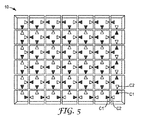
図5は、隣接する構成要素間の全てで同じタイプの連結を用いると仮定して、4つの異なるタイプの構成要素のみから、より大きいベース10をどうやって経済的に組み立てることができるのかを示している。図5では、この連結は、ある1つの構成要素の縁部上の濃い三角C1と、隣接する構成要素の縁部上の白い三角C2とによって示されている。図5で用いられる4つのタイプの構成要素は、図6a〜6dに示されており、1つのタイプの角部構成要素11(図6a)と、連結構成要素C1、C2の組み合わせのみが異なる2つのタイプの縁部構成要素12(図6b)及び13(図6c)と、1つのタイプの内側構成要素14(図6d)とを含む。代替形態として、1つのタイプの角部構成要素と、1つのタイプの縁部構成要素と、2つのタイプの内側構成要素とを用いて、同様のベースを組み立てることもできる。
FIG. 5 shows how a
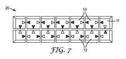
図7は、角部構成要素11(図6a)と、縁部構成要素12(図6b)及び13(図6c)のみを用いて、細長いベース20をどうやって組み立てることができるのかを示している。あるいは、図8に示されているように、図3のベースの構成要素8に似ている2つの末端部構成要素15と、1つ以上の中間構成要素16とを用いて、細長いベース21を組み立てることもできる。図8における構成要素間の連結は、概略的に示されているに過ぎず、好ましい連結システムについては、後で説明する。
FIG. 7 shows how the
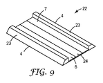
図2〜8を参照しながら説明されるベースの構成要素は、いずれかの適切な製造プロセスによって、最も好適には成型プロセスによって、作製することができる。更なる代替形態として、押出成形された構成要素から形成されるベースが図9に示されている。図9のベース22は、傾斜状縁部4が、ベースの2つの対向側面上のみにあるという点で、図2〜8を参照しながら説明したものとは異なり、その結果、使用中、縁部4がマットの全域で、通行体の正常方向に横断して延びるように、ベース22を含むマットを配置しなければならない。ベース22は、2つの全く同じ外側構成要素23であって、それぞれが、ベースの長さを延ばすと共に、縁部4の1つ、及び凹部7の床部6の隣接部分を含む外側構成要素23と、内側構成要素24であって、外側構成要素23と同様にベースの長さを延ばすと共に、床部6の中央部分を含む構成要素24とを含む。構成要素23と構成要素24との間の連結(見えない)は、押出プロセスによって、これらの構成要素を全て、ベース22に必要な長さに延長できるようになっている。好適な連結システムの例については、後で説明する。
The base components described with reference to FIGS. 2-8 can be made by any suitable manufacturing process, most preferably by a molding process. As a further alternative, a base formed from extruded components is shown in FIG. The
図10は、図9のベース22の修正形態を示しており、外側構成要素23’と内側構成要素24’が、直立壁25と共に形成されており、直立壁25の位置で、外側構成要素23’と内側構成要素24’が相互に隣接している。図9におけるような単一の凹部ではなく、マット材料を受容するための3つの縦方向に延びる凹部7’をベースが効果的に含むように、壁25はベースの長さを延ばす。完成されたマットが、マットの上を通過する通行体に、連続的な水平な表面を提供するように、壁25の上面は、傾斜状縁部4の頂部のように、凹部7’の中に置かれるマット材料の上面と同じ高さでなければならない。
FIG. 10 shows a modified form of the
所望に応じて、凹部7又は凹部7’を完全に取り囲むために、図9及び10の末端部に、何らかの形状の縁を固定することもできる。この追加的な縁は、任意の好適な方法で固定することができ、所望に応じて、縁部4によって提供されるもののような、ベースの末端部にある傾斜表面を提供できる。しかし、上記のように、用いる際に、縁部4がマットの全域で、通行体の垂直方向に横断して延びるように、ベースを含むマットが配置される場合には、この追加的な傾斜状表面は必須ではない。
If desired, some form of edge can be secured to the distal end of FIGS. 9 and 10 to completely enclose the
図11は、周辺部全体を取り囲む傾斜状縁部を有するベース30を組み立てる代替的な方法を示す分解図である。このケースでは、まず、ベースの所要周辺部寸法を有する矩形床部層31を準備する。この床部層は、例えばロール形状で提供される好適な材料の長さ部分から切断してもよい。それぞれが床部層の対応する側面の長さを有する4つの縁部片32も提供される。縁部片32は、傾斜状縁部4の所要の形に対応する概ねくさび形の横断面を有し、床部層同様に、例えばロール形状で提供される好適な材料の長さ部分から切断してもよい。続いて、ベース30の角部で留め継ぎを形成するように事前に付形された縁部片32(図11では、床部層31から切り離された状態で示されている)を、いずれかの好適な方法で、床部層31の縁を覆うように取り付けて、ベースの周辺部全体を取り囲むように間断なく延びる縁部をもたらす。必要に応じてベースを分解できるように、縁部片32の床部層31への取り付けは、再閉鎖可能な留め具によるものであってもよいし、接着剤による恒久的な取り付けであってもよい。
FIG. 11 is an exploded view showing an alternative method of assembling a base 30 having an inclined edge surrounding the entire periphery. In this case, first, a
別個の縁部片36を含む別のベース35の構築が図12に示されており、この図も分解図である。このケースでは、ベースの中央に、解放可能な形で併せて連結される複数の構成要素37を含み、この構成要素のそれぞれは、マット材料を受容するための対応する凹部38を有する。構成要素37を所望の形体で組み立てると、ベース35の角部で留め継ぎを形成するように事前に付形された縁部片36(図12では、ベースの中央から切り離された状態で示されている)を、周辺部を取り囲む位置で固定して、ベースの周辺部全体を取り囲むように間断なく延びる縁部をもたらす。したがって、完成されたマットは、各種凹部38内でタイル状に配列された複数の別個のマット材料片を含むことになる。図10を参照しながら上で説明したように、完成されたマットが、マットの上を通過する通行体に連続的な水平な表面を提供するように、凹部38の壁の上面は全て、凹部内に置かれるマット材料の上面と同じ高さでなければならない。
The construction of another base 35 including a
縁部片36は、必要に応じてベースを分解し、構成要素を再利用できるようにするいずれかの好適な方法で、ベース35の中央片37に固定することができる。縁部片36及び中央片37は、例えば、それぞれ、図16a及び16bを参照しながら下で説明されているタイプの、2つの部分からなる機械的連結具の1つの部分を備えることができる。
The
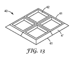
図13は、マット材料の別個の片を受容するための複数の凹部を提供する別のベース40を示している。このケースでは、ベース40の周辺部全体を取り囲むように間断なく延びている傾斜状縁部4”は、別個の縁部片からではなく、図2〜8のように、ベースを形成する構成要素41の一体部分である区画として形成される。構成要素41は、任意の好適な方法で、解放可能な形で併せて連結され、各構成要素は、好適に付形されたマット材料片が置かれる、対応する凹部42を有する。このケースでも、完成されたマットが、マットの上を通過する通行体に、連続的な水平な表面を提供するように、凹部42の壁の上面は全て、凹部内に置かれるマット材料の上面と同じ高さでなければならない。
FIG. 13 shows another base 40 that provides a plurality of recesses for receiving separate pieces of mat material. In this case, the
上記ベースの構成要素を併せて連結するのに用いることができる連結システムは、図14〜17に示されており、これについては以下で説明する。当然ながら、採用される連結システムは、併せて用いられることになる構成要素のタイプを考慮して選択しなければならない。 A connection system that can be used to connect together the components of the base is shown in FIGS. 14-17 and will be described below. Of course, the coupling system employed must be selected in view of the type of components that will be used together.
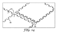
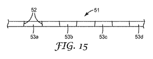
図14は、2つの構成要素の隣接する縁部沿いに、ほぞ穴−ほぞタイプの一連の接合部50を含む連結システムを示す斜視図である。構成要素51を併せて連結し、後に構成要素51を切り離すのに、構成要素51間の相対上下運動が必要となるように、各ほぞ穴/ほぞは、鳩尾型の形を有する。有益なことに、各ほぞの側面52は、垂直線からやや傾斜しており、その傾斜方向は互い違いになっており、これは図15の側面図に示されており、図15は、ほぞ53aの側面52が相互に、構成要素の上面から底面への方向で多少それているのに対して、隣接するほぞ53bの側面52は収束しており、また、他のほぞ53c、53dなども同様であることを示している。この結果、構成要素51を併せて連結し、後に構成要素51を引き離すには、ある程度の圧力が必要となり、これは、ひいては、特にベース内の凹部(1つ又は複数)からマット材料を取り外すときに、意図に反して構成要素が引き離されるのを防ぐ一助となる。
FIG. 14 is a perspective view showing a coupling system including a series of mortise-tenon type joints 50 along adjacent edges of two components. Each mortise / tenon has a dovetail shape so that relative up and down movement between the
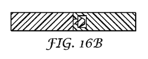
図16a及び16bは、構成要素を併せて連結し(図16b)、後に構成要素を引き離す(図16a)のに、2つの構成要素間の相対水平運動を必要とする連結システムを示す横断面図である。このケースでは、一方の構成要素56の側縁上の突出スタッド55は、他方の構成要素58の凹部57に押し込み嵌めされる。スタッド55は、マットベースが使用中であるときに、構成要素56、58が意図に反して切り離されるのを防ぐ付形されたヘッドを有する。このような複数の連結用スタッド/凹部は、必要に応じて、構成要素の1つの縁部沿いに提供することができる。
FIGS. 16a and 16b are cross-sectional views showing a connection system that requires relative horizontal movement between two components to connect the components together (FIG. 16b) and later pull the components apart (FIG. 16a). It is. In this case, the protruding
図17は、図9及び10に示されているベースの構成要素のような、押出成形された構成要素に特に適しているが、押出成形構成要素のみに適しているわけではない連結システムを示している。このシステムでは、適切に付形された溝60が、構成要素61の下方側面内に形成されており、構成要素61は、その縁部沿いで、隣接する構成要素に連結されることになる。連結片62が、この溝、及び、隣接する構成要素63の同様の溝の中に挿入され、その結果、2つの構成要素を併せて連結する。それぞれに見合った他の形状の連結システムを用いて、マットベースの構成要素を併せて連結できることは、明らかであろう。ただし、他の形状によって、マットベースの構成要素間に隙間が形成されないか、又は、形成される余地がないことを条件とする。
FIG. 17 shows a connection system that is particularly suitable for extruded components, such as the base component shown in FIGS. 9 and 10, but not only for extruded components. ing. In this system, a suitably shaped
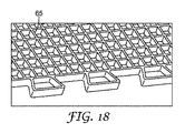
上記のようなベースの床接触面は、床に対するベースの動きを抑制するように設計するのが有益である。これは、例えば、床接触面の上に滑り止め材料又はパターンを提供することによって達成できる。図18は、交差リブ65を備えるマットベースの構成要素(このケースでは、図14の構成要素51の1つ)の下面を示しており、この交差リブも、望ましくない重量増なしに、より剛性な構造を達成する一助にもなる。上記の他のマットベースのいずれかの構成要素のいずれも、同様の構造を有することができるのは明らかであろう。
The base floor contact surface as described above is beneficially designed to inhibit movement of the base relative to the floor. This can be accomplished, for example, by providing a non-slip material or pattern on the floor contact surface. FIG. 18 shows the underside of the mat-base component (in this case one of the
任意の好適なマット材料を、図面を参照しながら上で説明したタイプのマットベースで用いることができる。1つの好適な材料は、本発明者の特許出願である英国特許第0620895.3号(2006年10月20日)、及び同第0703428.3号(2007年2月22日)に記載されている。好ましくは、マットが使用中であるときに、マット材料がベースに対して動かないようにするために、マット材料は、マットベースの凹部の床部に解放可能な形で固定される。凹部の床部は、例えば、マット材料と、又は、マット材料の底面に取り付けられたループ布地と直接嵌合する複数のフックを備えることができる。代替形態として、再付着性接着テープを用いて、マット材料を凹部の床部に固定することもできる。既に説明したように、マットベースの凹部の深さは、マット材料の上面が、ベースの傾斜状縁部の頂部と同じ高さになるようでなければならない。 Any suitable mat material can be used with a mat base of the type described above with reference to the drawings. One suitable material is described in the inventor's patent applications British Patent No. 0620895.3 (October 20, 2006) and No. 07033428.3 (February 22, 2007). Yes. Preferably, the mat material is releasably secured to the floor of the mat base recess to prevent the mat material from moving relative to the base when the mat is in use. The floor of the recess can comprise, for example, a plurality of hooks that fit directly with the mat material or a loop fabric attached to the bottom surface of the mat material. As an alternative, a reattachable adhesive tape can be used to secure the mat material to the floor of the recess. As already explained, the depth of the recess in the mat base must be such that the top surface of the mat material is at the same height as the top of the base beveled edge.
図面に示されているマットベースはいずれも矩形であるが、同様の方法で、他の形を有するベースを構築できることは明らかであろう。マット材料が置かれる凹部についても、他の形が可能であることは明らかであろう。 Although the mat bases shown in the drawings are all rectangular, it will be apparent that bases having other shapes can be constructed in a similar manner. It will be apparent that other shapes are possible for the recess in which the mat material is placed.
Claims (18)
Applications Claiming Priority (2)
| Application Number | Priority Date | Filing Date | Title |
|---|---|---|---|
| GBGB0707268.9A GB0707268D0 (en) | 2007-04-16 | 2007-04-16 | Base for a floor mat |
| PCT/US2008/060216 WO2008128172A1 (en) | 2007-04-16 | 2008-04-14 | Base for a floor mat |
Publications (2)
| Publication Number | Publication Date |
|---|---|
| JP2010524576A true JP2010524576A (en) | 2010-07-22 |
| JP2010524576A5 JP2010524576A5 (en) | 2011-05-12 |
Family
ID=38116772
Family Applications (1)
| Application Number | Title | Priority Date | Filing Date |
|---|---|---|---|
| JP2010504177A Pending JP2010524576A (en) | 2007-04-16 | 2008-04-14 | Base for floor mat |
Country Status (8)
| Country | Link |
|---|---|
| US (1) | US20110229692A1 (en) |
| EP (1) | EP2136685A4 (en) |
| JP (1) | JP2010524576A (en) |
| CN (1) | CN101657129A (en) |
| BR (1) | BRPI0809748A2 (en) |
| CA (1) | CA2683926A1 (en) |
| GB (1) | GB0707268D0 (en) |
| WO (1) | WO2008128172A1 (en) |
Cited By (2)
| Publication number | Priority date | Publication date | Assignee | Title |
|---|---|---|---|---|
| KR200488923Y1 (en) * | 2018-06-25 | 2019-04-04 | 변장수 | Pad change type mat |
| JP2021178507A (en) * | 2020-03-31 | 2021-11-18 | カール・フロイデンベルク・カー・ゲー | Thermoformable decorative material |
Families Citing this family (13)
| Publication number | Priority date | Publication date | Assignee | Title |
|---|---|---|---|---|
| GB0620907D0 (en) * | 2006-10-20 | 2006-11-29 | 3M Innovative Properties Co | Floor matting |
| US9340983B2 (en) | 2013-10-25 | 2016-05-17 | E.M.E.H., Inc. | Entrance floor system |
| USD771973S1 (en) | 2015-01-08 | 2016-11-22 | Macneil Ip Llc | Mat |
| USD796227S1 (en) * | 2015-01-08 | 2017-09-05 | Macneil Ip Llc | Outdoor mat |
| USD764837S1 (en) * | 2015-06-16 | 2016-08-30 | Wearwell, Inc. | Foot cleaning tray |
| USD810465S1 (en) | 2016-01-19 | 2018-02-20 | Parallax Group International, Llc | Reversible floor mat |
| US20180055266A1 (en) | 2016-08-24 | 2018-03-01 | Milliken & Company | Floor Mat with Hidden Base Component |
| US10827865B2 (en) * | 2017-10-24 | 2020-11-10 | Milliken & Company | Modular floor mat |
| USD862927S1 (en) * | 2017-12-20 | 2019-10-15 | John Levin | Mat assembly |
| US10716987B1 (en) * | 2018-04-03 | 2020-07-21 | Candace Baldwin | Sport training device |
| GB2577497A (en) * | 2018-09-25 | 2020-04-01 | Axis House Holdings Ltd | Floor covering apparatus |
| CN110123107A (en) * | 2019-05-24 | 2019-08-16 | 厦门绵羊抗疲劳垫有限公司 | A kind of standing pad |
| US10842303B1 (en) * | 2019-07-09 | 2020-11-24 | Checkers Industrial Products, Llc | Anti-fatigue mat |
Citations (2)
| Publication number | Priority date | Publication date | Assignee | Title |
|---|---|---|---|---|
| JPS63160775U (en) * | 1987-04-08 | 1988-10-20 | ||
| JP2003245107A (en) * | 2002-02-26 | 2003-09-02 | Duskin Co Ltd | Separate mat |
Family Cites Families (14)
| Publication number | Priority date | Publication date | Assignee | Title |
|---|---|---|---|---|
| US2436315A (en) * | 1946-01-23 | 1948-02-17 | Liberatore Gustavo Del Peschio | Door mat with scraper and removable brush |
| US3802144A (en) * | 1972-08-16 | 1974-04-09 | J Spica | Through- and under-draining flooring modules |
| DE3124529A1 (en) * | 1981-06-23 | 1983-01-05 | Heinrich Kampmann KG, 4450 Lingen | Foot-wiping entrance mat |
| US4568587A (en) * | 1981-09-25 | 1986-02-04 | Balco, Inc. | Roll-up floor mat with rigid rails |
| CA1191304A (en) * | 1983-02-23 | 1985-08-06 | Richard A. Morrison | Mat module with ramp strip |
| US4609580A (en) * | 1985-01-07 | 1986-09-02 | Kimberly-Clark Corporation | Absorbent floor mat |
| GB8821407D0 (en) * | 1988-09-13 | 1988-10-12 | Kimberly Clark Ltd | Improvements in & relating to mat holder |
| GB8928367D0 (en) * | 1989-12-15 | 1990-02-21 | Kimberly Clark Ltd | Improvements in and relating to mat holders |
| WO1992002163A1 (en) * | 1990-07-27 | 1992-02-20 | Cyrus Manufacturing Inc. | Modular carpet tile mat construction and process of making same |
| GB9122727D0 (en) * | 1991-10-25 | 1991-12-11 | Sutherland Thomas L | Improvements in entrance matting |
| GB9700518D0 (en) * | 1997-01-11 | 1997-02-26 | Milliken Denmark | Edging system |
| SE9801307D0 (en) * | 1998-04-16 | 1998-04-16 | Act Ab | Carpet for use at entrances and the like for wiping shoes or other dirty items |
| US6886209B2 (en) * | 1999-05-04 | 2005-05-03 | Tech Mats, Llc | Advanced floor mat |
| CA2390828C (en) * | 2002-06-17 | 2012-05-15 | Quinn Holtby | Safety mat |
-
2007
- 2007-04-16 GB GBGB0707268.9A patent/GB0707268D0/en not_active Ceased
-
2008
- 2008-04-14 WO PCT/US2008/060216 patent/WO2008128172A1/en active Application Filing
- 2008-04-14 BR BRPI0809748-8A2A patent/BRPI0809748A2/en not_active IP Right Cessation
- 2008-04-14 EP EP08745751A patent/EP2136685A4/en not_active Withdrawn
- 2008-04-14 CN CN200880012182A patent/CN101657129A/en active Pending
- 2008-04-14 JP JP2010504177A patent/JP2010524576A/en active Pending
- 2008-04-14 CA CA002683926A patent/CA2683926A1/en not_active Abandoned
- 2008-04-14 US US12/595,977 patent/US20110229692A1/en not_active Abandoned
Patent Citations (2)
| Publication number | Priority date | Publication date | Assignee | Title |
|---|---|---|---|---|
| JPS63160775U (en) * | 1987-04-08 | 1988-10-20 | ||
| JP2003245107A (en) * | 2002-02-26 | 2003-09-02 | Duskin Co Ltd | Separate mat |
Cited By (3)
| Publication number | Priority date | Publication date | Assignee | Title |
|---|---|---|---|---|
| KR200488923Y1 (en) * | 2018-06-25 | 2019-04-04 | 변장수 | Pad change type mat |
| JP2021178507A (en) * | 2020-03-31 | 2021-11-18 | カール・フロイデンベルク・カー・ゲー | Thermoformable decorative material |
| JP7326365B2 (en) | 2020-03-31 | 2023-08-15 | カール・フロイデンベルク・カー・ゲー | thermoformable decorative material |
Also Published As
| Publication number | Publication date |
|---|---|
| EP2136685A4 (en) | 2012-03-21 |
| GB0707268D0 (en) | 2007-05-23 |
| CN101657129A (en) | 2010-02-24 |
| EP2136685A1 (en) | 2009-12-30 |
| US20110229692A1 (en) | 2011-09-22 |
| WO2008128172A1 (en) | 2008-10-23 |
| CA2683926A1 (en) | 2008-10-23 |
| BRPI0809748A2 (en) | 2014-09-30 |
Similar Documents
| Publication | Publication Date | Title |
|---|---|---|
| JP2010524576A (en) | Base for floor mat | |
| US7571573B2 (en) | Modular floor tile with lower cross rib | |
| EP0541531B1 (en) | Mat base and modular carpet tile mat construction | |
| US6505444B1 (en) | Free standing modular floor mat system | |
| US20140007525A1 (en) | Joint devices, systems, and methods for exterior flooring | |
| WO2010048750A1 (en) | New type of plastic ground mat | |
| CA2446263C (en) | Spillage control safety floor matting | |
| CA2595060C (en) | Modular mat | |
| US20020119275A1 (en) | Modular mats and edging system therefor | |
| JPH09486A (en) | Hood grill | |
| US5992105A (en) | Spillage control safety floor matting | |
| US7028434B2 (en) | Spillage control safety floor matting | |
| WO2007100379A2 (en) | Integrated edge and corner ramp for a floor tile | |
| JP2004332527A (en) | Decoration plate unit | |
| JP2848424B2 (en) | Combination decorative board | |
| KR101850497B1 (en) | modularized assembly structure of floor | |
| US20090249732A1 (en) | Modular floor system | |
| WO2006111834A1 (en) | Floor and floor panels | |
| JPH0321391Y2 (en) | ||
| JPH0246582Y2 (en) | ||
| JP3068323U (en) | Three-layer wood-assembled floorboard | |
| US20200123787A1 (en) | Floor Covering Apparatus | |
| JP3050920U (en) | Floor structure | |
| FR2791076A1 (en) | Flexible slab for ground covering of technical premises has mating male and female parts for assembling to adjacent slabs | |
| JPH09273293A (en) | Floor finish material and construction method thereof |
Legal Events
| Date | Code | Title | Description |
|---|---|---|---|
| A521 | Written amendment |
Free format text: JAPANESE INTERMEDIATE CODE: A523 Effective date: 20110316 |
|
| A621 | Written request for application examination |
Free format text: JAPANESE INTERMEDIATE CODE: A621 Effective date: 20110316 |
|
| A977 | Report on retrieval |
Free format text: JAPANESE INTERMEDIATE CODE: A971007 Effective date: 20120517 |
|
| A131 | Notification of reasons for refusal |
Free format text: JAPANESE INTERMEDIATE CODE: A131 Effective date: 20120605 |
|
| A02 | Decision of refusal |
Free format text: JAPANESE INTERMEDIATE CODE: A02 Effective date: 20121218 |