JP2010524249A - Thermal management system for electronic devices - Google Patents
Thermal management system for electronic devices Download PDFInfo
- Publication number
- JP2010524249A JP2010524249A JP2010502600A JP2010502600A JP2010524249A JP 2010524249 A JP2010524249 A JP 2010524249A JP 2010502600 A JP2010502600 A JP 2010502600A JP 2010502600 A JP2010502600 A JP 2010502600A JP 2010524249 A JP2010524249 A JP 2010524249A
- Authority
- JP
- Japan
- Prior art keywords
- airflow
- thermal management
- inlet
- expansion
- management device
- Prior art date
- Legal status (The legal status is an assumption and is not a legal conclusion. Google has not performed a legal analysis and makes no representation as to the accuracy of the status listed.)
- Pending
Links
Images
Classifications
-
- F—MECHANICAL ENGINEERING; LIGHTING; HEATING; WEAPONS; BLASTING
- F04—POSITIVE - DISPLACEMENT MACHINES FOR LIQUIDS; PUMPS FOR LIQUIDS OR ELASTIC FLUIDS
- F04D—NON-POSITIVE-DISPLACEMENT PUMPS
- F04D25/00—Pumping installations or systems
- F04D25/02—Units comprising pumps and their driving means
- F04D25/08—Units comprising pumps and their driving means the working fluid being air, e.g. for ventilation
- F04D25/082—Units comprising pumps and their driving means the working fluid being air, e.g. for ventilation the unit having provision for cooling the motor
-
- F—MECHANICAL ENGINEERING; LIGHTING; HEATING; WEAPONS; BLASTING
- F04—POSITIVE - DISPLACEMENT MACHINES FOR LIQUIDS; PUMPS FOR LIQUIDS OR ELASTIC FLUIDS
- F04D—NON-POSITIVE-DISPLACEMENT PUMPS
- F04D29/00—Details, component parts, or accessories
- F04D29/58—Cooling; Heating; Diminishing heat transfer
- F04D29/5806—Cooling the drive system
-
- G—PHYSICS
- G06—COMPUTING; CALCULATING OR COUNTING
- G06F—ELECTRIC DIGITAL DATA PROCESSING
- G06F1/00—Details not covered by groups G06F3/00 - G06F13/00 and G06F21/00
- G06F1/16—Constructional details or arrangements
- G06F1/20—Cooling means
-
- G—PHYSICS
- G06—COMPUTING; CALCULATING OR COUNTING
- G06F—ELECTRIC DIGITAL DATA PROCESSING
- G06F1/00—Details not covered by groups G06F3/00 - G06F13/00 and G06F21/00
- G06F1/16—Constructional details or arrangements
- G06F1/20—Cooling means
- G06F1/206—Cooling means comprising thermal management
-
- H—ELECTRICITY
- H05—ELECTRIC TECHNIQUES NOT OTHERWISE PROVIDED FOR
- H05K—PRINTED CIRCUITS; CASINGS OR CONSTRUCTIONAL DETAILS OF ELECTRIC APPARATUS; MANUFACTURE OF ASSEMBLAGES OF ELECTRICAL COMPONENTS
- H05K7/00—Constructional details common to different types of electric apparatus
- H05K7/20—Modifications to facilitate cooling, ventilating, or heating
- H05K7/20709—Modifications to facilitate cooling, ventilating, or heating for server racks or cabinets; for data centers, e.g. 19-inch computer racks
- H05K7/20718—Forced ventilation of a gaseous coolant
- H05K7/20727—Forced ventilation of a gaseous coolant within server blades for removing heat from heat source
Landscapes
- Engineering & Computer Science (AREA)
- General Engineering & Computer Science (AREA)
- Physics & Mathematics (AREA)
- Theoretical Computer Science (AREA)
- Mechanical Engineering (AREA)
- Thermal Sciences (AREA)
- Microelectronics & Electronic Packaging (AREA)
- Human Computer Interaction (AREA)
- General Physics & Mathematics (AREA)
- Computer Hardware Design (AREA)
- Cooling Or The Like Of Electrical Apparatus (AREA)
- Cooling Or The Like Of Semiconductors Or Solid State Devices (AREA)
Abstract
電子装置のエアムーバまたは受動形ヒートシンクといった構成変更可能な複数の入口を備える熱管理装置である。熱管理装置は、計算装置に、または拡張モジュール等といった計算装置類の構成要素に配置され、それにより流入気流が熱発生構成要素の温度を低下させる。最善に可能な気流を供給するために、エアムーバは、エアムーバ構成要素の少なくとも一方側から気流に圧力をかける羽根設計を備える。エアムーバは、所要の方向からの吸気に必要な開口を与えるとともにファン送風を供給するための脱着可能カバーを含む。用途に応じて、開口は永続的に開放または閉鎖されていてもよい。吸気流はその後、熱発生要素に向けてファン送風の形態で誘導される。A thermal management device comprising a plurality of reconfigurable inlets such as an air mover or passive heat sink of an electronic device. The thermal management device is placed in a computing device or a component of a computing device such as an expansion module so that the incoming airflow reduces the temperature of the heat generating component. In order to provide the best possible airflow, the air mover comprises a vane design that exerts pressure on the airflow from at least one side of the air mover component. The air mover includes a removable cover for providing an opening necessary for intake from a required direction and supplying fan air. Depending on the application, the opening may be permanently open or closed. The intake air flow is then induced in the form of a fan blow towards the heat generating element.
Description
本発明は電子装置における熱管理に関する。 The present invention relates to thermal management in electronic devices.
長年にわたってコンピュータグラフィックスはけた外れに進歩してきた。解像度は著しく増加し、グラフィックス生成は品質強化機能とともに改善されている。同様に、顧客は表示されるグラフィックスの品質に関してより要求が多くなっている。高品質グラフィックスは、映画、ビデオクリップ、ワールドワイドウェブページ、ゲーム、ユーザインタフェース等といった複数の様々な用途において必要とされている。この高品質コンテンツを生成するために当然より多くの資源もまた必要とされる。このように、グラフィックス計算能力は実際上すべての計算装置において必要とされている。 Over the years, computer graphics have made tremendous progress. Resolution has increased significantly and graphics generation has been improved with quality enhancement features. Similarly, customers are more demanding regarding the quality of the graphics displayed. High quality graphics are required in a number of different applications such as movies, video clips, world wide web pages, games, user interfaces, and the like. Of course, more resources are also needed to produce this high quality content. Thus, graphics computing power is required in virtually all computing devices.
実際には、グラフィックス計算能力を向上させる2つの方法が存在する。第1はより良好なアルゴリズムおよび機能の導入であり、第2はハードウェア計算容量を増大させることによって計算能力を高めることである。これは、より高速な処理装置を使用する、処理装置の数を増やす、そして基板上により多くのメモリを使用することによって達成することができる。最善の結果が達成されるように同時に両方の方法で取り組むことが一般的な手法である。 In practice, there are two ways to improve graphics computing power. The first is the introduction of better algorithms and functions, and the second is to increase computing power by increasing the hardware computing capacity. This can be achieved by using faster processing equipment, increasing the number of processing equipment, and using more memory on the substrate. It is common practice to work in both ways simultaneously to achieve the best results.
より多くの高速なハードウェア構成要素を備えることによって計算能力を高めるうえでの1つの問題は、増大する電力消費および発熱である。たとえ新しいより電力効率のよいハードウェア構成要素が製造されたとしても、増大した効率に起因する電力消費のあらゆる可能な節約が、より多くのハードウェアを使用することにより高品質グラフィックスを生成するために使用されることになりそうである。 One problem in increasing computing power by having more fast hardware components is increased power consumption and heat generation. Even if new, more power-efficient hardware components are manufactured, any possible savings in power consumption due to increased efficiency produces high quality graphics by using more hardware Is likely to be used for.
近年、特定の用途における高品質グラフィックスの要求は、コンピュータにおいて単一のグラフィックス装置を使用することによりその要求された品質を提供することが極めて難しいか不可能であるほどに大きくなっている。グラフィックス装置は一般に、コンピュータまたはワークステーションの主回路板に取付けられた拡張カードである。一般に、追加のカードを主回路板に取付けるための数個のスロットが存在する。従って、明らかな解決策は、同一コンピュータ内に取付けられた他のグラフィックス装置と協働できるグラフィックス装置を提供することである。二重取付けは数年にわたり知られており、それらは最も要求の厳しい顧客に容易な解決策を提供する。 In recent years, the demand for high quality graphics in specific applications has become so great that it is extremely difficult or impossible to provide that required quality by using a single graphics device in a computer. . The graphics device is typically an expansion card attached to the main circuit board of a computer or workstation. In general, there are several slots for attaching additional cards to the main circuit board. Thus, an obvious solution is to provide a graphics device that can work with other graphics devices mounted in the same computer. Double installations have been known for several years and they provide an easy solution for the most demanding customers.
典型的な構成では、2個以上のまったく類似のグラフィックス装置が協働モードで作業するために取付けられる。協働モードが最も要求の厳しい使用者を対象にされると、その構成で使用されるグラフィックスカードは最も効率的なもののうちの1つであることが普通である。これは、高い電力消費および発熱を伴う複数のグラフィックス装置が存在することを意味する。コンピュータの他の構成要素もまた熱を発生するので、計算装置および装置内の別個の構成要素の換気は極めて重要になる。 In a typical configuration, two or more identical graphics devices are attached to work in a collaborative mode. When the collaborative mode is targeted to the most demanding users, the graphics card used in that configuration is usually one of the most efficient. This means that there are multiple graphics devices with high power consumption and heat generation. Since other components of the computer also generate heat, ventilation of the computing device and the separate components within the device becomes extremely important.
一般に、中央処理装置およびグラフィックス処理装置といったコンピュータにおいて最も多くの熱を発生する構成要素は、向上した換気のために各自自身のファンを有する。他の解決策は、発生した熱を伝達することができる受動形熱管理システムを熱発生構成要素に備えることである。 In general, the most heat generating components in computers such as central processing units and graphics processing units have their own fans for improved ventilation. Another solution is to provide the heat generating component with a passive heat management system that can transfer the generated heat.
しかし、類似の装置に関してこれは、換気が両方の熱管理解決策において隣り合う装置によって妨害されるかもしれないので、問題を含むかもしれない。換気が妨害された場合、装置の温度は動作温度を超えて上昇し、計算エラーまたは装置の動作の停止を生じるか、さもなければ装置を(一般に低下した性能をもたらす)低下した電力消費で動作するように強いるかもしれない。グラフィックスカードに加えて、類似の問題は他の種類の拡張カードでも遭遇し得る。従って、計算装置のための、特にグラフィックス装置のための改善された換気の必要性が存在する。 However, for similar devices this may be problematic because ventilation may be disturbed by neighboring devices in both thermal management solutions. If ventilation is interrupted, the temperature of the device will rise above the operating temperature, resulting in a calculation error or device shutdown, or otherwise operating the device with reduced power consumption (generally resulting in reduced performance) May be strong to do. In addition to graphics cards, similar problems can be encountered with other types of expansion cards. Accordingly, there is a need for improved ventilation for computing devices, particularly for graphics devices.
実施形態において、本発明は開放環境において構成変更可能な(configurable)空気取入口を備える熱管理装置を開示する。本発明は、ファンおよびヒートシンクを含む受動形または能動形熱管理システムで使用することができる。本発明に従った熱管理装置は、調整可能な吸気管理を備えており、気流は、吸気を所要の方向に誘導するように構成された脱着可能カバーおよび/または特殊側板によって制御される。 In an embodiment, the present invention discloses a thermal management device with a configurable air intake in an open environment. The present invention can be used in passive or active thermal management systems including fans and heat sinks. The thermal management device according to the present invention comprises adjustable intake management, wherein the airflow is controlled by a removable cover and / or special side plate configured to guide the intake air in the required direction.
実施形態において、熱管理装置は、電子装置のための構成変更可能な複数入口エアムーバ構成要素である。本発明に従ったエアムーバは、計算装置に、または拡張カード等といった計算装置類の構成要素に配置され、それにより流入気流が熱発生構成要素の温度を低下させる。最善に可能な気流を供給するために、エアムーバは、羽根がモータにより動かされるとエアムーバ構成要素の少なくとも一方側から気流に圧力をかける羽根設計を備える。エアムーバは、所要の方向からの吸気に必要な開口を与えるとともにファン生成気流を供給するための脱着可能カバーを含む。用途に応じて、開口は永続的に開放または閉鎖されていてもよい。吸気流はその後、熱発生要素に向けてファン生成気流の形態で誘導される。 In an embodiment, the thermal management device is a configurable multiple inlet air mover component for an electronic device. The air mover according to the present invention is arranged in a computing device or in a component of a computing device such as an expansion card, whereby the incoming airflow reduces the temperature of the heat generating component. In order to provide the best possible airflow, the air mover comprises a blade design that applies pressure to the airflow from at least one side of the air mover component when the blade is moved by a motor. The air mover includes a removable cover for providing an opening necessary for intake from a required direction and supplying a fan-generated airflow. Depending on the application, the opening may be permanently open or closed. The intake air flow is then induced in the form of a fan-generated air flow towards the heat generating element.
実施形態において、エアムーバはさらに、気流を所要の方向に誘導するための脱着可能カバーを有する複数の気流出口を備える。 In an embodiment, the air mover further comprises a plurality of airflow outlets having removable covers for guiding the airflow in the required direction.
実施形態において、熱管理装置はさらに、より構成変更可能な空気取入口を与えるように構成された特殊な側板を備える。側板はエアムーバ、ヒートシンクまたは熱伝達要素に配置され、それによりそれは可能なインピーダンス領域の外部から吸気流を取り入れる。側板は、熱伝達要素の吸気流方向を制御するように構成されており、前記側板は、少なくとも1つの隣り合う装置に起因する気流抵抗(気流インピーダンス(air flow impedance))による影響を受ける気流を少なくとも部分的に阻止するように構成されている。実施形態において、側板は掩蔽可能な入口開口を備える。 In an embodiment, the thermal management device further comprises a special side plate configured to provide a more reconfigurable air intake. The side plate is placed on an air mover, heat sink or heat transfer element so that it takes in the intake flow from outside the possible impedance region. The side plate is configured to control the direction of intake air flow of the heat transfer element, and the side plate is configured to control an air flow affected by air flow resistance (air flow impedance) caused by at least one adjacent device. It is configured to at least partially block. In an embodiment, the side plate comprises an closable inlet opening.
上述の実施形態は、種々の用途の種々の要件を満たす熱管理装置を生産するために組合せてもよい。例えば、能動形および受動形の熱管理の両方を組合せ、組合せたものに掩蔽可能な開口を有する特殊な側板を備えることが可能である。 The embodiments described above may be combined to produce a thermal management device that meets different requirements for different applications. For example, it is possible to combine both active and passive thermal management, and to provide a special side plate with an opening that can be covered by the combination.
本発明の効果は、それが、隣り合う装置によって発生する気流インピーダンスにより妨害されることなく、または妨害を少なくして、所要の構成要素に向けて適切な吸気流を供給するということである。これは、より良好な気流を、従ってより良好な冷却を可能にする。これは、数個の熱発生要素を収容する小さな計算装置ケース容積を扱う際に極めて重要である。 The advantage of the present invention is that it provides adequate inspiratory flow towards the required components without or with less disturbance by the airflow impedance generated by the adjacent devices. This allows for better airflow and thus better cooling. This is extremely important when dealing with small computer case volumes that contain several heat generating elements.
本発明のさらなる効果は、所要の構成要素が標準ヒートシンクを装備できることである。従来の技術によれば、ヒートシンクは換気システムに合わせて設計され、従って設計プロセスの複雑さを追加させなければならない。 A further advantage of the present invention is that the required components can be equipped with standard heat sinks. According to the prior art, the heat sink must be designed for the ventilation system and thus add to the complexity of the design process.
本発明のさらなる理解を与えこの明細書の一部を構成するために含まれた添付図面は、本発明の実施形態を例示し説明と併せて本発明の原理を解説するのを助ける。 The accompanying drawings, which are included to provide a further understanding of the invention and constitute a part of this specification, illustrate embodiments of the invention and, together with the description, help explain the principles of the invention.
ここで、その実例が添付図面に例示されている本発明の実施形態に詳細に言及する。 Reference will now be made in detail to embodiments of the invention, examples of which are illustrated in the accompanying drawings.
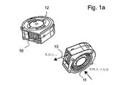
図1aには、本発明に従ったエアムーバの異なる2図が開示されている。本実施形態に従ったエアムーバは、気流出口10、吸気流のための常時入口11および常時入口のための脱着可能カバー12を備える。本実施形態はまた類似の常時入口をエアムーバの反対側にも含む。反対側の入口は図1cに見ることができる。他の実施形態において、換気を改善するために必要な場合、さらなる開口を作ることが可能である。しかし、これらの開口もまた脱着可能カバーを備える。さらなる開口は入口または出口気流について設けてもよい。
FIG. 1a discloses two different views of an air mover according to the present invention. The air mover according to the present embodiment includes an
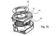
図1bは図1aの実施形態の分解図である。図1bのエアムーバは、気流を供給するために羽根およびモータを含む通気(air-moving)機構13、常時入口開口11を有するハウジング14および開口の1つのための脱着可能カバー12を備える。本発明が3つ以上の開口で具体化される場合、1つの開口だけを開放されたままとするなら、より多くのカバーもまた必要である。脱着可能カバー12はラッチまたは他の取付機構によってカバーに好適に取付けられる。1実施形態において、カバーは、装置の使用者がカバーを着脱するために工具を使用しなくて済むようにする機構を採用する。しかし、カバー12にいずれかの既知の取付手段を使用することが可能である。
FIG. 1b is an exploded view of the embodiment of FIG. 1a. The air mover of FIG. 1b comprises an air-moving
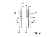
図2には、本発明の例示実施形態のブロック図が開示されている。図2では2つの通気構成要素が拡張モジュールに取付けられている。図2の実施形態において、拡張モジュールはホストコンピュータの主回路板に取付けられた拡張モジュール20および21である。拡張モジュールは、パーソナルコンピュータ、ワークステーションまたは類似物といった計算装置に取付けられ得る、あらゆる拡張カード、モジュールまたは類似物であるとしてよい。明快さの理由で、ホストコンピュータの主回路板は図には呈示されていない。拡張モジュールおよび主回路板が適切なバスによって接続されていることは当業者には明らかである。適切なバスは一般に拡張スロットの形態で具体化され、それにより複数の拡張カードが計算装置に取付けられ得る。図2には、拡張モジュール20および21が例示されており、それらは隣り合うスロットと接続されている。
FIG. 2 discloses a block diagram of an exemplary embodiment of the present invention. In FIG. 2, two ventilation components are attached to the expansion module. In the embodiment of FIG. 2, the expansion modules are
図2の拡張モジュールは、図1に開示されたエアムーバといったエアムーバ22および23を備えている。図2の実施形態で使用されるエアムーバは、2つの常時入口を有する。入口は、エアムーバの両方において隣り合う拡張モジュールの隣の入口が覆われ、気流24および25が本実施形態における入口気流を呈するように構成される。このように、入口気流24および25は、隣り合う拡張モジュールのエアムーバによって発生する気流インピーダンスによって妨害されない。図2の実施形態において、出口気流はその後、熱発生構成要素26および27に誘導される。熱発生構成要素の例は拡張モジュールの処理装置である。熱発生構成要素26および27は、図示されていないヒートシンクを備えていてもよい。図2の実施形態はこのようにして、気流インピーダンスによって妨害されることなく熱発生要素に向けて気流を効率的に供給する。
The expansion module of FIG. 2 includes
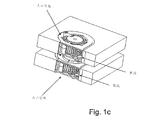
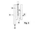
図3の実施形態は図2の実施形態と異なり、モジュールのうちの1つが側板を有する。モジュール31は図2のモジュール21と類似であり、熱管理要素33は気流35を所要の方向に誘導するエアムーバである。モジュール30は側板32を備えている。側板32の下に能動形または受動形熱管理システムが存在してもよい。側板の目的は、モジュール31のエアムーバ33に類似の熱管理システムでは可能でないはずの方向から吸気流34を誘導することである。
The embodiment of FIG. 3 differs from the embodiment of FIG. 2 in that one of the modules has a side plate. The
当業者は十分理解される通り、本発明はここで、ラックまたはブレード型計算装置内部のサーバ、コンピュータシステム、装置に等しく適用することができる。例えば、ブレード型またはブレード形式計算装置は当業者には周知である。複数のブレード型計算装置が互いにごく接近してラックシステム内に取付けられ得る。気流を改善して、互いに近接する複数の羽根により生じる相反する空気の吸入要件に起因する通気抵抗(通気インピーダンス(air movement impedance))を減少させるために、本発明は例えばブレード型計算装置の各々に適用することができよう。すなわち、ブレード型計算装置全体のためのハウジングは、2つの吸気口、出口(または排気口)および計算装置ハウジング内部に配設されたファンといった通気機構を有するとしてよい。2つの隣接する別のブレード型計算装置の吸気口は各々、通気インピーダンスを低減するために閉じる(または部分的に閉じる)ことができよう。代替として、複数のブレード型サーバ装置の各々のための入口が装置の各々の上面および底面にあるとすれば、計算装置の各々の上面吸気口は計算装置のラック全体を通じて空気インピーダンスを低減するために閉じる(または部分的に閉じるかまたは閉鎖する)ことができよう。 As will be appreciated by those skilled in the art, the present invention is now equally applicable to servers, computer systems, equipment within rack or blade computing devices. For example, blade type or blade type computing devices are well known to those skilled in the art. Multiple blade computing devices can be mounted in a rack system in close proximity to one another. In order to improve airflow and reduce ventilation resistance (air movement impedance) due to conflicting air inhalation requirements caused by a plurality of blades in close proximity to each other, the present invention, for example, each of the blade-type computing devices Could be applied to. That is, the housing for the entire blade-type computing device may have a ventilation mechanism such as two intake ports, an outlet (or exhaust port), and a fan disposed inside the computing device housing. The inlets of two adjacent separate blade computing devices could each be closed (or partially closed) to reduce ventilation impedance. Alternatively, if the inlets for each of the plurality of blade-type server devices are on the top and bottom surfaces of each of the devices, each top air intake of the computing device reduces air impedance throughout the computing device rack. Could be closed (or partially closed or closed).
技術の進歩により本発明の基本的な考案が様々なやり方で具体化され得ることは当業者には明らかである。従って本発明およびその実施形態は上述の実例に限定されず、むしろそれらはクレームの適用範囲内で異なってもよい。 It will be apparent to those skilled in the art that with the advancement of technology, the basic idea of the present invention can be embodied in various ways. The invention and its embodiments are thus not limited to the examples described above, but rather they may vary within the scope of the claims.
Claims (23)
前記熱管理装置は、気流を発生させるための通気装置を収容するためのハウジングを備えており、
前記ハウジングは、
流入空気のための少なくとも2つの常時入口開口と、
前記通気装置によって発生した気流のための少なくとも1つの開口と、
を含むことを特徴とする熱管理装置。 A thermal management device for an electronic device,
The thermal management device includes a housing for housing a ventilation device for generating an airflow,
The housing is
At least two permanent inlet openings for the incoming air;
At least one opening for airflow generated by the venting device;
A thermal management device comprising:
前記熱管理装置は、気流を発生させるための通気装置を収容するためのハウジングを備えており、
前記ハウジングは、流入空気のための少なくとも2つの入口開口と、
前記通気装置によって発生した気流のための少なくとも1つの開口と、
を備えることを特徴とするシステム。 A system comprising a thermal management device for supplying airflow,
The thermal management device includes a housing for housing a ventilation device for generating an airflow,
The housing includes at least two inlet openings for incoming air;
At least one opening for the air flow generated by the venting device;
A system comprising:
熱伝達要素と、
前記熱伝達要素の吸気流の方向を制御するように構成された側板と、
を備えており、
前記側板は、少なくとも1つの隣接する装置による気流抵抗の影響を受ける気流を少なくとも部分的に阻止するように構成されていることを特徴とする装置。 A device for supplying a reconfigurable intake flow for thermal management,
A heat transfer element;
A side plate configured to control the direction of intake flow of the heat transfer element;
With
The apparatus, wherein the side plate is configured to at least partially block airflow that is affected by airflow resistance by at least one adjacent apparatus.
熱伝達要素と、
前記熱伝達要素の吸気流の方向を制御するように構成された側板と、
を備えており、
前記側板は、少なくとも1つの隣接する装置による気流抵抗の影響を受ける気流を阻止するように構成されていることを特徴とする拡張カード。 A computer expansion card comprising a device for supplying a reconfigurable intake flow for thermal management,
A heat transfer element;
A side plate configured to control the direction of intake flow of the heat transfer element;
With
The expansion card according to claim 1, wherein the side plate is configured to block an airflow affected by an airflow resistance by at least one adjacent device.
前記方法は、
前記少なくとも2つの拡張モジュールのうちの少なくとも1つの拡張モジュールの吸気口を形成することによって、前記少なくとも1つの拡張モジュールとは別の拡張モジュールによる気流抵抗を低減することを含み、
前記少なくとも2つの拡張モジュールの各々は前記吸気口を備える熱管理装置を有していることを含むことを特徴とする方法。 A method for operating a computer system comprising at least two expansion modules, comprising:
The method
Reducing airflow resistance by an expansion module different from the at least one expansion module by forming an inlet of at least one expansion module of the at least two expansion modules;
Each of the at least two expansion modules includes a thermal management device with the inlet.
Applications Claiming Priority (2)
| Application Number | Priority Date | Filing Date | Title |
|---|---|---|---|
| US11/733,586 US20080253087A1 (en) | 2007-04-10 | 2007-04-10 | Thermal management system for an electronic device |
| PCT/IB2008/000857 WO2008122878A2 (en) | 2007-04-10 | 2008-04-09 | Thermal management system for an electronic device |
Publications (1)
| Publication Number | Publication Date |
|---|---|
| JP2010524249A true JP2010524249A (en) | 2010-07-15 |
Family
ID=39831477
Family Applications (1)
| Application Number | Title | Priority Date | Filing Date |
|---|---|---|---|
| JP2010502600A Pending JP2010524249A (en) | 2007-04-10 | 2008-04-09 | Thermal management system for electronic devices |
Country Status (7)
| Country | Link |
|---|---|
| US (1) | US20080253087A1 (en) |
| EP (1) | EP2138022A4 (en) |
| JP (1) | JP2010524249A (en) |
| KR (1) | KR20100016420A (en) |
| CN (1) | CN101715657A (en) |
| TW (1) | TW200910072A (en) |
| WO (1) | WO2008122878A2 (en) |
Families Citing this family (5)
| Publication number | Priority date | Publication date | Assignee | Title |
|---|---|---|---|---|
| WO2013082314A1 (en) | 2011-11-29 | 2013-06-06 | Cooper Technologies Company | Shroud for an electrical enclosure |
| US20140334091A1 (en) * | 2013-05-07 | 2014-11-13 | Nvidia Corporation | Counter rotating blower with individual controllable fan speeds |
| US20160369819A1 (en) * | 2014-07-31 | 2016-12-22 | Gentherm Incorporated | Air mover inlet interface and cover |
| CN110520702A (en) * | 2017-04-18 | 2019-11-29 | 惠普发展公司,有限责任合伙企业 | Monitor the heat health of electronic equipment |
| US10219365B1 (en) * | 2018-02-23 | 2019-02-26 | Quanta Computer Inc. | Bidirectional and uniform cooling for multiple components in a computing device |
Citations (4)
| Publication number | Priority date | Publication date | Assignee | Title |
|---|---|---|---|---|
| JPS61166197U (en) * | 1985-04-03 | 1986-10-15 | ||
| JP3102608U (en) * | 2003-12-26 | 2004-07-15 | 國大 張 | Structure of heat dissipation device |
| JP2005516425A (en) * | 2002-01-30 | 2005-06-02 | エレル,デイビット | Heat sink with large fin-to-air contact area |
| JP2005197535A (en) * | 2004-01-08 | 2005-07-21 | Toshiba Home Technology Corp | Cooling module |
Family Cites Families (14)
| Publication number | Priority date | Publication date | Assignee | Title |
|---|---|---|---|---|
| US3209988A (en) * | 1964-06-24 | 1965-10-05 | Clements Mfg Co | Hot air blower |
| JP2744772B2 (en) * | 1995-05-31 | 1998-04-28 | 山洋電気株式会社 | Blowers and blowers for cooling electronic components |
| US6452797B1 (en) * | 1997-11-12 | 2002-09-17 | Intel Corporation | Fan-cooled card |
| JP3377182B2 (en) * | 1999-03-31 | 2003-02-17 | 東芝ホームテクノ株式会社 | Fan motor |
| US6671177B1 (en) * | 2002-10-25 | 2003-12-30 | Evga.Com Corporation | Graphics card apparatus with improved heat dissipation |
| US6822863B1 (en) * | 2003-08-18 | 2004-11-23 | Dell Products L.P. | Airflow shroud mounted fan system and method for cooling information handling system components |
| US8720532B2 (en) * | 2004-04-29 | 2014-05-13 | Hewlett-Packard Development Company, L.P. | Controllable flow resistance in a cooling apparatus |
| KR20060016236A (en) * | 2004-08-17 | 2006-02-22 | 신태영 | Extension circuit structure inserted in desk top personal computer |
| US20060078423A1 (en) * | 2004-10-08 | 2006-04-13 | Nonlinear Tech, Inc. | Bi-directional Blowers for Cooling Laptop Computers |
| JP4461484B2 (en) * | 2004-12-10 | 2010-05-12 | 東芝ホームテクノ株式会社 | Fan motor |
| US7486519B2 (en) * | 2006-02-24 | 2009-02-03 | Nvidia Corporation | System for cooling a heat-generating electronic device with increased air flow |
| US20070280818A1 (en) * | 2006-06-01 | 2007-12-06 | Chih-Heng Yang | Heat-Dissipating Fan |
| US7529085B2 (en) * | 2006-06-30 | 2009-05-05 | Lenovo (Singapore) Pte. Ltd. | Thermal docking fansink |
| US7443672B2 (en) * | 2006-10-03 | 2008-10-28 | Fu Zhun Precision Industry (Shen Zhen) Co., Ltd. | Video graphics array (VGA) card assembly |
-
2007
- 2007-04-10 US US11/733,586 patent/US20080253087A1/en not_active Abandoned
-
2008
- 2008-04-09 WO PCT/IB2008/000857 patent/WO2008122878A2/en active Application Filing
- 2008-04-09 CN CN200880018441A patent/CN101715657A/en active Pending
- 2008-04-09 EP EP08737401A patent/EP2138022A4/en not_active Withdrawn
- 2008-04-09 JP JP2010502600A patent/JP2010524249A/en active Pending
- 2008-04-09 KR KR1020097023477A patent/KR20100016420A/en not_active Application Discontinuation
- 2008-04-10 TW TW097112954A patent/TW200910072A/en unknown
Patent Citations (4)
| Publication number | Priority date | Publication date | Assignee | Title |
|---|---|---|---|---|
| JPS61166197U (en) * | 1985-04-03 | 1986-10-15 | ||
| JP2005516425A (en) * | 2002-01-30 | 2005-06-02 | エレル,デイビット | Heat sink with large fin-to-air contact area |
| JP3102608U (en) * | 2003-12-26 | 2004-07-15 | 國大 張 | Structure of heat dissipation device |
| JP2005197535A (en) * | 2004-01-08 | 2005-07-21 | Toshiba Home Technology Corp | Cooling module |
Also Published As
| Publication number | Publication date |
|---|---|
| TW200910072A (en) | 2009-03-01 |
| EP2138022A4 (en) | 2011-05-04 |
| US20080253087A1 (en) | 2008-10-16 |
| EP2138022A2 (en) | 2009-12-30 |
| WO2008122878A3 (en) | 2008-12-04 |
| KR20100016420A (en) | 2010-02-12 |
| CN101715657A (en) | 2010-05-26 |
| WO2008122878A2 (en) | 2008-10-16 |
Similar Documents
| Publication | Publication Date | Title |
|---|---|---|
| JP5043037B2 (en) | Airflow management system for electronic equipment chassis | |
| TWI566679B (en) | Server system | |
| US8953312B2 (en) | Electronic device and casing for electronic device | |
| KR101492320B1 (en) | Network communication apparatus | |
| JP5296595B2 (en) | Thermal management device and thermal management method | |
| US8472181B2 (en) | Computer cabinets having progressive air velocity cooling systems and associated methods of manufacture and use | |
| US7535707B2 (en) | Power supply cooling system | |
| EP1133906B1 (en) | Parallel cooling of high power devices in a serially cooled environment | |
| US8817470B2 (en) | Electronic device and complex electronic device | |
| JP4994503B2 (en) | Arithmetic processing unit | |
| JP2015532759A (en) | Axis for electronic equipment | |
| US20090201639A1 (en) | Chassis of portable electronic apparatus | |
| JP2010524249A (en) | Thermal management system for electronic devices | |
| GB2401251A (en) | Circuit card divider | |
| US7450380B2 (en) | Computer system having multi-direction blower | |
| US20150163959A1 (en) | Electronic device with fan module | |
| EP3422833B1 (en) | Arc shape front panel | |
| CN110286726B (en) | Host system and heat dissipation device and separation mechanism thereof | |
| CN212009483U (en) | Computer device | |
| JP6621153B1 (en) | Server device and cooling method | |
| US20240074091A1 (en) | Directed cooling in heat producing systems | |
| CN113741640A (en) | Computer device | |
| CN112925399A (en) | Laptop computer with display side cooling system | |
| CN115686145A (en) | Server and cabinet | |
| JP2016040718A (en) | Network communication device |
Legal Events
| Date | Code | Title | Description |
|---|---|---|---|
| A621 | Written request for application examination |
Free format text: JAPANESE INTERMEDIATE CODE: A621 Effective date: 20101224 |
|
| A131 | Notification of reasons for refusal |
Free format text: JAPANESE INTERMEDIATE CODE: A131 Effective date: 20120807 |
|
| A601 | Written request for extension of time |
Free format text: JAPANESE INTERMEDIATE CODE: A601 Effective date: 20121106 |
|
| A602 | Written permission of extension of time |
Free format text: JAPANESE INTERMEDIATE CODE: A602 Effective date: 20121114 |
|
| A02 | Decision of refusal |
Free format text: JAPANESE INTERMEDIATE CODE: A02 Effective date: 20130219 |