JP2010524154A - Terminal devices, connectors, and adapters - Google Patents
Terminal devices, connectors, and adapters Download PDFInfo
- Publication number
- JP2010524154A JP2010524154A JP2010501043A JP2010501043A JP2010524154A JP 2010524154 A JP2010524154 A JP 2010524154A JP 2010501043 A JP2010501043 A JP 2010501043A JP 2010501043 A JP2010501043 A JP 2010501043A JP 2010524154 A JP2010524154 A JP 2010524154A
- Authority
- JP
- Japan
- Prior art keywords
- solder
- terminal device
- contact
- terminal
- insulator
- Prior art date
- Legal status (The legal status is an assumption and is not a legal conclusion. Google has not performed a legal analysis and makes no representation as to the accuracy of the status listed.)
- Withdrawn
Links
- 229910000679 solder Inorganic materials 0.000 claims abstract description 162
- 239000012212 insulator Substances 0.000 claims abstract description 66
- 238000004519 manufacturing process Methods 0.000 claims abstract description 9
- 238000000034 method Methods 0.000 claims description 14
- 230000007704 transition Effects 0.000 claims description 10
- 238000000926 separation method Methods 0.000 claims description 8
- 238000005476 soldering Methods 0.000 abstract description 30
- 238000010276 construction Methods 0.000 abstract 1
- 238000005452 bending Methods 0.000 description 3
- 239000000463 material Substances 0.000 description 3
- RYGMFSIKBFXOCR-UHFFFAOYSA-N Copper Chemical compound [Cu] RYGMFSIKBFXOCR-UHFFFAOYSA-N 0.000 description 2
- 230000015572 biosynthetic process Effects 0.000 description 2
- 229910052802 copper Inorganic materials 0.000 description 2
- 239000010949 copper Substances 0.000 description 2
- 238000004891 communication Methods 0.000 description 1
- 238000000280 densification Methods 0.000 description 1
- 239000002184 metal Substances 0.000 description 1
- 229910052751 metal Inorganic materials 0.000 description 1
- 238000012986 modification Methods 0.000 description 1
- 230000004048 modification Effects 0.000 description 1
- 230000000149 penetrating effect Effects 0.000 description 1
- 230000002093 peripheral effect Effects 0.000 description 1
Images
Classifications
-
- H—ELECTRICITY
- H01—ELECTRIC ELEMENTS
- H01R—ELECTRICALLY-CONDUCTIVE CONNECTIONS; STRUCTURAL ASSOCIATIONS OF A PLURALITY OF MUTUALLY-INSULATED ELECTRICAL CONNECTING ELEMENTS; COUPLING DEVICES; CURRENT COLLECTORS
- H01R31/00—Coupling parts supported only by co-operation with counterpart
- H01R31/06—Intermediate parts for linking two coupling parts, e.g. adapter
-
- H—ELECTRICITY
- H01—ELECTRIC ELEMENTS
- H01R—ELECTRICALLY-CONDUCTIVE CONNECTIONS; STRUCTURAL ASSOCIATIONS OF A PLURALITY OF MUTUALLY-INSULATED ELECTRICAL CONNECTING ELEMENTS; COUPLING DEVICES; CURRENT COLLECTORS
- H01R4/00—Electrically-conductive connections between two or more conductive members in direct contact, i.e. touching one another; Means for effecting or maintaining such contact; Electrically-conductive connections having two or more spaced connecting locations for conductors and using contact members penetrating insulation
- H01R4/02—Soldered or welded connections
- H01R4/023—Soldered or welded connections between cables or wires and terminals
- H01R4/024—Soldered or welded connections between cables or wires and terminals comprising preapplied solder
-
- H—ELECTRICITY
- H01—ELECTRIC ELEMENTS
- H01R—ELECTRICALLY-CONDUCTIVE CONNECTIONS; STRUCTURAL ASSOCIATIONS OF A PLURALITY OF MUTUALLY-INSULATED ELECTRICAL CONNECTING ELEMENTS; COUPLING DEVICES; CURRENT COLLECTORS
- H01R43/00—Apparatus or processes specially adapted for manufacturing, assembling, maintaining, or repairing of line connectors or current collectors or for joining electric conductors
- H01R43/02—Apparatus or processes specially adapted for manufacturing, assembling, maintaining, or repairing of line connectors or current collectors or for joining electric conductors for soldered or welded connections
- H01R43/0249—Apparatus or processes specially adapted for manufacturing, assembling, maintaining, or repairing of line connectors or current collectors or for joining electric conductors for soldered or welded connections for simultaneous welding or soldering of a plurality of wires to contact elements
-
- H—ELECTRICITY
- H01—ELECTRIC ELEMENTS
- H01R—ELECTRICALLY-CONDUCTIVE CONNECTIONS; STRUCTURAL ASSOCIATIONS OF A PLURALITY OF MUTUALLY-INSULATED ELECTRICAL CONNECTING ELEMENTS; COUPLING DEVICES; CURRENT COLLECTORS
- H01R43/00—Apparatus or processes specially adapted for manufacturing, assembling, maintaining, or repairing of line connectors or current collectors or for joining electric conductors
- H01R43/16—Apparatus or processes specially adapted for manufacturing, assembling, maintaining, or repairing of line connectors or current collectors or for joining electric conductors for manufacturing contact members, e.g. by punching and by bending
-
- Y—GENERAL TAGGING OF NEW TECHNOLOGICAL DEVELOPMENTS; GENERAL TAGGING OF CROSS-SECTIONAL TECHNOLOGIES SPANNING OVER SEVERAL SECTIONS OF THE IPC; TECHNICAL SUBJECTS COVERED BY FORMER USPC CROSS-REFERENCE ART COLLECTIONS [XRACs] AND DIGESTS
- Y10—TECHNICAL SUBJECTS COVERED BY FORMER USPC
- Y10T—TECHNICAL SUBJECTS COVERED BY FORMER US CLASSIFICATION
- Y10T29/00—Metal working
- Y10T29/49—Method of mechanical manufacture
- Y10T29/49002—Electrical device making
- Y10T29/49117—Conductor or circuit manufacturing
- Y10T29/49204—Contact or terminal manufacturing
Landscapes
- Engineering & Computer Science (AREA)
- Manufacturing & Machinery (AREA)
- Coupling Device And Connection With Printed Circuit (AREA)
- Multi-Conductor Connections (AREA)
Abstract
本発明は、端子デバイスに関しており、これは、それの表面に形成されたはんだスロットを包含する絶縁体と;本体部分及び本体部分の端部に形成されたはんだ端子部分を包含する、及びその厚さよりも大きい幅を包含する接点とを含み、はんだ端子部分が垂直にはんだスロット内に置かれて、はんだ端子部分の幅方向がはんだスロットの深さ方向に実質的に一致するようにされたものである。本発明の少なくとも1つの実施形態は、ファインピッチコネクタの接点をケーブルにはんだ付けしている間に生じる問題点を少なくとも部分的に及び効果的に解決し、並びに構造が簡単であって製造コストが低い。 The present invention relates to a terminal device, which includes an insulator including a solder slot formed on a surface thereof; a body portion and a solder terminal portion formed at an end of the body portion; and a thickness thereof. And a contact that includes a width greater than the height of the solder terminal, the solder terminal portion being vertically placed in the solder slot such that the width direction of the solder terminal portion substantially coincides with the depth direction of the solder slot. It is. At least one embodiment of the present invention solves at least partially and effectively the problems that occur while soldering the contacts of a fine pitch connector to a cable, and is simple in construction and low in manufacturing costs. Low.
Description
本発明は、端子デバイスに関するものであり、より特にはファインピッチのコネクタ用に適合された、並びに優れたはんだ付け施工特性及び高い信頼性を有する、はんだ型の端子デバイスに関する。本発明はまた、上述のはんだ型端子デバイスを包含するコネクタと、上述のコネクタを包含するアダプタとに関する。 The present invention relates to a terminal device, and more particularly to a solder-type terminal device adapted for fine pitch connectors and having excellent soldering characteristics and high reliability. The invention also relates to a connector that includes the solder-type terminal device described above and an adapter that includes the connector described above.
はんだ型のケーブルコネクタは、世界市場で広範囲に使用されている。ケーブルが複数の電線を含んで、コネクタが対応する端子デバイスを含む場合に、ケーブルにはんだ付けされるファインピッチコネクタを達成するためには、小型化及び高密度化の進展が必要とされる。端子デバイスは、小ピッチの間隔で離された、複数の接点を含むものである。組立中に、それぞれの電線が、対応する接点のはんだ端子部分にはんだ付けされ、このようにして、電気的接続が達成される。 Solder-type cable connectors are widely used in the global market. In order to achieve a fine pitch connector that is soldered to a cable when the cable includes multiple wires and the connector includes a corresponding terminal device, advances in miniaturization and densification are required. The terminal device includes a plurality of contacts separated by a small pitch. During assembly, each wire is soldered to the solder terminal portion of the corresponding contact, and thus an electrical connection is achieved.
ファインピッチコネクタをケーブルにはんだ付けするとき、伝統的に、ケーブルのそれぞれの電線が、接点のはんだ端子部分のそれぞれに上から水平に置かれ、次の問題に帰着する:第一に、隣接するはんだ付けユニット間のピッチが小さいので、接点のはんだ端子部分と対応する電線との間の有効接触面積が減少し、これにより、はんだ付けの施工特性が劣って、はんだ付けの信頼性が低下する;第二に、隣接するはんだ付けユニット間のピッチが小さいので、隣接するはんだ付けユニット間の間隔が減少し、その結果、隣接するはんだ付け位置の間で短絡が生じる傾向があり、したがって、はんだ付け施工を難しいものにし、はんだ付けの信頼性を低下させる。 When soldering a fine pitch connector to a cable, traditionally, each wire of the cable is placed horizontally on each of the solder terminal portions of the contact, resulting in the following problems: First, adjacent Since the pitch between the soldering units is small, the effective contact area between the solder terminal portion of the contact and the corresponding electric wire is reduced, which results in inferior soldering performance and lowers the soldering reliability. Secondly, because the pitch between adjacent soldering units is small, the spacing between adjacent soldering units is reduced, and as a result, there is a tendency to short circuit between adjacent soldering locations, thus It makes soldering difficult and reduces the reliability of soldering.
ある場合には、幾つかの電気的仕様及び性能の要求を満たすために、大ゲージの電線をファインピッチコネクタの接点にはんだ付けすることが必要となり、その場合、前述の問題がより深刻になる。 In some cases, it may be necessary to solder a large gauge wire to the contacts of a fine pitch connector to meet some electrical specifications and performance requirements, in which case the aforementioned problems become more serious .
本発明の少なくとも1つの実施形態は、従来技術中に存在する前述の問題の少なくとも1つの態様を解決することを対象とする。 At least one embodiment of the present invention is directed to overcoming at least one aspect of the aforementioned problems present in the prior art.
本発明の第一の実施形態は、端子デバイスの表面内に形成されたはんだスロットを包含する絶縁体と、本体部分及び本体部分の端部に形成されたはんだ端子部分を包含して、その厚さよりも広い幅を有する接点と、を含み、はんだ端子部分の幅方向が、はんだスロットの深さ方向に実質的に一致するように、はんだ端子部分が垂直にはんだスロット内に置かれる、端子デバイスを提供する。 A first embodiment of the present invention includes an insulator including a solder slot formed in a surface of a terminal device, a body portion and a solder terminal portion formed at an end of the body portion, and its thickness. A terminal device, wherein the solder terminal portion is vertically positioned in the solder slot such that the width direction of the solder terminal portion substantially coincides with the depth direction of the solder slot I will provide a.
第一の実施形態では、端子デバイスが、ケーブルの電線をファインピッチコネクタの接点にはんだ付けする間に生じる問題点の少なくとも1つの態様を解決する。加えて、端子デバイスは、構造が簡単であってコストが低い。 In the first embodiment, the terminal device solves at least one aspect of the problems that arise during soldering of the cable wires to the contacts of the fine pitch connector. In addition, the terminal device is simple in structure and low in cost.
本発明の第二の実施形態は、端子デバイスの表面内に形成されたはんだスロットを包含する絶縁体を準備する工程と、本体部分及び本体部分の端部に形成されたはんだ端子部分を包含して、その厚さよりも広い幅を有する接点を準備する工程と、はんだ端子部分の幅方向が前記はんだスロットの深さ方向に実質的に一致するように、前記はんだ端子部分を垂直に前記はんだスロット内に置く工程とを、含む端子デバイスを製造する方法を提供する。 A second embodiment of the present invention includes providing an insulator including a solder slot formed in a surface of a terminal device, and including a body portion and a solder terminal portion formed at an end of the body portion. Providing a contact having a width wider than the thickness of the solder slot, and vertically extending the solder terminal portion so that the width direction of the solder terminal portion substantially coincides with the depth direction of the solder slot. A method of manufacturing a terminal device comprising the steps of:
第二の実施形態では、端子デバイスを製造する方法が、ケーブルの電線をファインピッチコネクタの接点にはんだ付けする間に生じる問題点の少なくとも1つの態様を解決する。加えて、その方法は、プロセスが簡単であってコストが低い。 In a second embodiment, a method of manufacturing a terminal device solves at least one aspect of the problems that arise during soldering of cable wires to fine-pitch connector contacts. In addition, the method is simple in process and low in cost.
本発明の第三の実施形態は、本発明の第一の実施形態による端子デバイスを含むコネクタを提供することである。 The third embodiment of the present invention is to provide a connector including a terminal device according to the first embodiment of the present invention.
この第三の実施形態のコネクタがあれば、はんだ付け施工が迅速に実行可能になり、コネクタが大ゲージの電線にはんだ付けされる場合でさえ、はんだ付けの信頼性及び製造プロセスの安定性が高い。同時に、優れた電気的性能が達成可能であり、コストが低い。 With the connector of this third embodiment, the soldering operation can be performed quickly, and the reliability of the soldering and the stability of the manufacturing process are ensured even when the connector is soldered to a large gauge wire. high. At the same time, excellent electrical performance can be achieved and the cost is low.
本発明の第四の実施形態は、本発明の第三の実施形態によるコネクタを包含するアダプタを提供することである。 The fourth embodiment of the present invention is to provide an adapter including a connector according to the third embodiment of the present invention.
本発明の実施形態が、添付図面を参照して詳細に説明されるが、本明細書に記述される実施形態は、説明及び例示用であって、本発明を制限すると解釈されるものではない。説明を通して、同一要素は、類似参照番号で示される。 While embodiments of the present invention will be described in detail with reference to the accompanying drawings, the embodiments described herein are for purposes of illustration and illustration and are not to be construed as limiting the invention. . Throughout the description, identical elements are indicated with similar reference numerals.
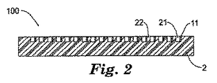
本発明の実施形態による端子デバイス100は、図2〜3及び6〜7に示されるように、実質的に直方体形状の絶縁体2と、複数の接点1とを含む。
A
それぞれの接点1は、図1に示されるように、本体部分12と、本体部分12の端部に形成されたはんだ端子部分11とを含み、はんだ端子部分11は、厚さと厚さよりも大きい幅と所定の長さとを含む。より詳しくは、本体部分12は、図1及び5に示されるように、ねじり部分120、遷移部分121、保持部分122、及び接点部分123を含む。
As shown in FIG. 1, each contact 1 includes a
この実施形態では、はんだ端子部分11は平らであり、例えば、はんだ端子部分11は、シートの形体であってもよい。
In this embodiment, the
この実施形態では、複数のはんだスロット21が、絶縁体2の上面(図1〜3の上側表面)に並んで形成されて、同一距離で間隔を離され、及び絶縁体2の上面を貫いて侵入している。換言すれば、はんだスロット21の長手方向は、(図4aに示されるように)絶縁体2の幅方向に一致する。隣接するはんだスロット21は、分離リブ22により間隔を離されている。図2〜4に示される実施形態では、はんだスロット21は、同一の幅及び深さを有する。
In this embodiment, a plurality of
図2〜4に示されるように、複数の接点1はそれぞれ、はんだ端子部分11の幅方向がはんだスロット21の深さ方向に一致するように、スロット21内に置かれている。
As shown in FIGS. 2 to 4, each of the plurality of contacts 1 is placed in the
図3及び4に示される実施形態では、はんだ端子部分11は、はんだスロット21の側壁に対して当接するように、はんだスロット21内に置かれている。したがって、ケーブル5の電線51がはんだ端子部分11にはんだ付けされる時、電線51の前側端部511が、はんだスロット21内ではんだスロット21の側面に置かれる。その結果、このことは、はんだ材料7がはんだ端子部分11及び電線51に接触することを可能にして、はんだ端子部分11と電線51のはんだ付けに利益となるようにしており、便宜が良い。同時に、はんだ端子部分11を垂直にはんだスロット21内に置くことによって、はんだ付けユニット間の小さいピッチに起因する制限が、幾分かは解消でき、はんだ端子部分11の有効なはんだ付け面積を得ることができる。その上、隣接するはんだスロット21の間の分離リブ22は、はんだ付けユニット間で短絡が生じるのを効果的に防止することができる。
In the embodiment shown in FIGS. 3 and 4, the
ここで、用語「はんだ付けユニット」は、はんだスロット21内のはんだ端子部分11にはんだ付け材料7で、電線51をはんだ付けすることにより形成される、ユニットを意味する。
Here, the term “soldering unit” means a unit formed by soldering the
上記実施形態では、絶縁体2は、ほぼ直方体形状を含むが、本発明は、これに限定されない。例えば、絶縁体2は、円形断面を有することが可能であり、絶縁体2の周囲表面にはんだスロット21を形成することが可能である。
In the said embodiment, although the
上記実施形態では、複数のはんだスロット21は、絶縁体2の上面に形成されて、同一距離で間隔を離されており、はんだスロット21は、同一の深さ及び幅を有する。しかしながら、本発明は、これに限定されない。例えば、はんだスロット21は、はんだ付けされる電線51のゲージに基づいて、異なる深さ及び幅を有することができる。その上、はんだ付けされる電線51の数により、はんだスロット21は、いかなる好適な数にもすることができる。例えば、1本の電線51の場合、1つのはんだスロット21だけが、形成を必要とされる。加えて、複数のはんだスロット21は、非同一距離の間隔を有することが可能である。
In the above embodiment, the plurality of
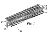
上記実施形態では、はんだスロット21は、直方体の絶縁体2の上面に形成されている。別の実施形態では、はんだスロット21は、図6及び7に示されるように、絶縁体2の上面及び下面に同時に形成することができる。更に、上面に形成されるはんだスロット21は、下面に形成されるものに対称とすることができる。
In the above embodiment, the
図2〜4では、はんだスロット21は矩形断面を含むが、はんだスロット21の断面は、U形状及び正方形など、いかなる好適な形状にもすることができる。本発明の実施形態では、はんだスロット21の底面は、平らな面として、又は下向きに斜めに傾いて形成することができる。あるいは、はんだスロット21の底面の形状が接点1の形状に適合するように、はんだスロット21の底面が、面取りを含むことができる。
2-4, the
本発明の実施形態によるケーブルコネクタ200を以下で説明する。
A
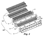
本発明の実施形態によるコネクタ200は、図5に示されるように、端子デバイス100、更なる絶縁体3、及び金属の遮蔽シュラウド4を含む。
A
図5では、端子デバイス100の2列の接点1は、複数のはんだスロット21が上面及び下面に含まれる絶縁体2から分離されている、すなわち、接点1のはんだ端子部分11は、はんだスロット21内に置かれていない。
In FIG. 5, the two rows of contacts 1 of the
図1及び6を参照して、接点1の構造及び形成方法を以下で説明する。 With reference to FIGS. 1 and 6, the structure and formation method of the contact 1 will be described below.
本発明の実施形態では、それぞれの接点1は、一片の平らなシート部材(例えば銅シート)を含み、シート部材に、はんだ端子部分11が、本体部分12の1つの端部に形成される。初期状態では、はんだ端子部分11と本体部分12は、同一平面内に位置する。すなわち、はんだ端子部分11の幅方向は、本体部分12のそれと一致する。図1を参照して、本体部分12は、その長手方向に沿って延びる長手方向中心軸線L1を有し、はんだ端子部分11は、その長手方向に沿って延びる長手方向中心軸線L2を有する。長手方向中心軸線L1と長手方向中心軸線L2は、相互に実質的に平行であり、接点1の幅方向に予め定められた距離で相互に間隔を有する。はんだ端子部分11は、はんだ端子部分11が本体部分12に関して垂直状態に位置するように、はんだ端子部分11の形成中に、その長手方向軸線に平行な予め定められた軸線周りで、約90度曲げられるか、又はねじられる。結果として、はんだ端子部分11の幅方向と本体部分12の幅方向は、相互に直交する。
In an embodiment of the present invention, each contact 1 includes a piece of flat sheet member (e.g., a copper sheet), on which the
図1及び6に示されるように、はんだ端子部分11には、溝が形成される。その結果、はんだ端子部分11のねじり又は曲げの間のねじり力が、効果的に減少され、はんだ端子部分11のねじり又は曲げの間の割れ又は破断の発生が、効果的に防止される。ねじり又は曲げ施工の間に、本体部分12のはんだ端子部分11に接続する部分が、ねじり部分又は曲げ部分120を形成するように変形される。一実施形態では、ねじり部分又は曲げ部分120は、はんだ端子部分11の平面及び本体部分12のそれに接する。
As shown in FIGS. 1 and 6, a groove is formed in the
初期状態では、端子部分11の長手方向中心軸線は、本体部分12のそれとも一致し得ることを特記しなければならない。換言すれば、はんだ端子部分11と本体部分12は、同一の長手方向中心軸線を有する。接点11の端部(すなわち末端部)を接点11の長手方向軸線周りで90度ねじることによって、はんだ端子部分11は、図1及び6に示されるように、本体部分12に相対的に垂直方向になり、本体部分12のねじり部分120に繋がっている。
It should be noted that in the initial state, the longitudinal central axis of the
図1及び5に示される実施形態では、それぞれの接点1は、ほぼZ形状を有する。 In the embodiment shown in FIGS. 1 and 5, each contact 1 has a generally Z shape.
上述のように、本体部分12は、ねじり部分120、遷移部分121、保持部分122、及び接点部分123を含む。ねじり部分120は、はんだ端子部分11に繋がっている。保持部分122は、接点1のほぼ中心に位置する垂直部分により形成され、接点1を絶縁体2に取り付けるために、絶縁体2への取付けがされるべきである。
As described above, the
遷移部分121は、ねじり部分120と保持部分122の上端部との間に位置しているので、はんだ端子部分11が遷移部分121に関して90度ねじられるとは、換言すると、遷移部分121の幅方向が、はんだ端子部分11のそれに対して実質的に直交することである。ねじり部分120は、はんだ端子部分11と遷移部分121とを連結する。一実施形態では、図1及び6に示されるように、ねじり部分120と遷移部分121とを連結している遷移する部分は、複数の接点が相互に隣接して配置されるときに干渉が生じるのを回避するために、面取りされる。
Since the
接点部分123は、保持部分122の下側端部に繋がる、接点1の水平部分により形成される。特に、接点部分123は、弾性支持部1231、巻き付き接点部1233、及び突出接点部1232を含む。
The
弾性支持部1231は、保持部分122の下側端部に繋がる、接点部分123の水平部分により形成される。
The
巻き付き接点部1233は、接点部分123の保持部分122から遠い自由端に形成されており、すなわち、巻き付き接点部1233は、接点部分123の自由端の短い部分により形成される。端子デバイス100がコネクタ200の形成に使用されるとき、巻き付き接点部1233は、コネクタ200の更なる絶縁体3に接触、及び更なる絶縁体3に相対的な位置付けを予定される(以降で説明)。
The
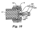
突出接点部1232は、弾性支持部1231と巻き付き接点部1233との間に位置して(図10にて最も良く見られるように)上向きに突き出しており、突出接点部1232は、別のコネクタに接続される予定であり、そのようにして電気的接続を達成する。接点1を側面から見る時、突出接点部1232は、図9及び10に示されるように、ほぼ弧形状を有する。
The protruding
本発明の実施形態による端子デバイス100を製造する方法を以下に説明する。
A method for manufacturing the
本発明の実施形態により、まず、図2に示されるようなほぼ直方体の絶縁体2が準備され、これには、複数のはんだスロット21が、絶縁体2の上面に形成されている。
According to the embodiment of the present invention, first, a substantially
次に、本体部分12及びはんだ端子部分11をそれぞれが有する複数の接点1が準備され、そのはんだ端子部分11は、平らであって、厚さと厚さより大きい幅と所定の長さとを包含する。
Next, a plurality of contacts 1 each having a
最後に、それぞれの接点1のはんだ端子部分11が、対応するはんだスロット21の側壁に対して当接するように、対応するはんだスロット21内に垂直に置かれ、これにより、それぞれのはんだ端子部分11の幅方向が、対応するはんだスロット21の深さ方向に一致する。したがって、本発明の実施形態による端子デバイス100が、図4に示されるように、達成される。
Finally, the
本発明の実施形態によれば、はんだ端子部分11は、はんだスロット21の側壁に隣接するようにはんだスロット21内に置かれる。少なくとも1つの実施形態では、はんだスロット21は、同一距離の離された間隔で並んで形成され、同一の深さ及び幅を有する。
According to an embodiment of the present invention, the
本発明の更なる実施形態によれば、複数のはんだスロット21が、絶縁体2の下面にも形成され、下面に形成されたはんだスロット21が、同一距離の間隔をおいて離されて、同一の深さ及び幅を有しており、その結果、2列の接点1が、図5に示されるように、上面及び下面にそれぞれ形成されたはんだスロット21内に置かれる。
According to a further embodiment of the present invention, a plurality of
上記のように、この実施形態では、はんだスロット21は、ほぼ矩形の断面を含む。しかしながら、本発明は、これに限定されない。
As described above, in this embodiment, the
更に特には、それぞれの接点1は、一片の銅シートなどの平部材により形成され、はんだ端子部分11は、接点1の端部をその長手方向軸線周りで90度ねじることにより形成され、本体部分12のはんだ端子部分11に繋がる部分は、ねじり部分120として形成される。接点1は、そのほぼ中心部分で2回曲げられており、その結果、接点1は、ほぼZ形状を有する。この実施形態によれば、接点1は、より簡単に及び低コストで製造できる。
More particularly, each contact 1 is formed by a flat member such as a piece of copper sheet, and the
更に、Z形状接点1の水平の接点部分123の中央部が、上向きに突き出して、突出接点部1232を形成するようになっており、突出接点部1232は、別のコネクタへの接続に使用される。Z形状接点1の垂直部分が、保持部分122として形成され、保持部分122は、絶縁体2への固定に使用されるものであり、このようにして、図6及び7に示されるように、接点1が絶縁体2に固定される。遷移部分121が、保持部分122とねじり部分120との間に存在する。コネクタ200の更なる絶縁体3との接触のための巻き付き接点部1233が、接点部分123の自由端に位置しており、更なる絶縁体3のビーム部分332に対して位置決めされる。
Further, the central portion of the
本発明の前述の実施形態によれば、端子デバイスは、構造が簡単であって製造コストが低く、ファインピッチコネクタをケーブルにはんだ付けする間に従来生じた問題点を、ある程度は解決することができる。加えて、本発明の端子デバイスは、はんだ付け施工特性の向上、製造プロセスの安定性及びはんだ付け信頼性の増大において、有利である。大ゲージ電線の場合、上記利点及び特徴が、より明らかになる。 According to the above-described embodiment of the present invention, the terminal device has a simple structure and low manufacturing cost, and can solve to some extent the problems that have conventionally occurred while soldering the fine pitch connector to the cable. it can. In addition, the terminal device of the present invention is advantageous in improving the soldering characteristics, in the stability of the manufacturing process, and in increasing the soldering reliability. In the case of a large gauge wire, the above advantages and features become more apparent.
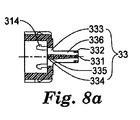
図8は、コネクタの更なる絶縁体の斜視図を、図8aは、その断面図を示しており、図9は、図7の端子デバイスの斜視図を、及び図9aは、その断面図を示している。簡略化の目的で、1列の接点だけが、図7の絶縁体2上に配置されている。
8 shows a perspective view of a further insulator of the connector, FIG. 8a shows a cross-sectional view thereof, FIG. 9 shows a perspective view of the terminal device of FIG. 7, and FIG. 9a shows a cross-sectional view thereof. Show. For the sake of simplicity, only one row of contacts is arranged on the
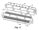
図9及び10に示される如く、2列の接点1が、端子デバイス100を形成するように、絶縁体2に組み立てられるとき、端子デバイス100は、更なる絶縁体3に対して組立て可能となり、次に、シュラウド4に組立て可能であり、これにより、図11に示されるように、コネクタ200が達成される。
9 and 10, when two rows of contacts 1 are assembled to the
端子デバイス100の更なる絶縁体3への組立ての後では、絶縁体2及び接点1は、図10に示されるように、更なる絶縁体3の後ろ部分に形成された空洞に部分的に受け入れられている。
After assembly of the
この実施形態では、絶縁体2は、ほぼ直方体形状を含み、複数のはんだスロット21が、絶縁体2の上面及び下面のそれぞれに形成されて、同一距離で間隔をおいて離されている。はんだスロット21は、同一の幅及び深さと、ほぼ矩形の断面とを有する。2列の形態の接点1が、絶縁体2の上面及び下面のそれぞれに形成されたはんだスロット21の中に配置されている。
In this embodiment, the
図5、6、及び7に示されるように、絶縁体2の両端部に形成された構造が、絶縁体2を更なる絶縁体3に取り付けるのに使用され、これについては、以降で詳細に説明される。
As shown in FIGS. 5, 6, and 7, the structures formed at both ends of the
図8、10、及び12を参照して、更なる絶縁体3は、本体31と、本体31から前向きに延びる舌部32とを含む。本体31の後ろ部分には、空洞が形成されている。複数のチャネル33が、舌部32の上面及び下面に形成されて、舌部32の長手方向に舌部32を貫いて、及び本体31の一部を長手方向に通って空洞と連通するようになっている。チャネル33はそれぞれ、絶縁体2に取り付けられる接点1に対応する。
With reference to FIGS. 8, 10, and 12, the
それぞれのチャネル33は、その前側端部に、前側方形穴部分331を有して形成される。前側方形穴部分331は、舌部32の長手方向に及び舌部32の前側端面を貫いて延びて、同時に、舌部32の上面に形成されたチャネル33は部分的に上向きに開き、舌部32の下面に形成されたチャネル33は部分的に下向きにそれぞれ開いており、その結果、ビーム部分332が、それぞれのチャネル33の前側端部に形成される。
Each
それぞれのチャネル33は、その後ろ側端部に、比較的大きい寸法の後ろ側方形穴部分333を有して形成される。後ろ側方形穴部分333は、本体31の一部を貫いて空洞と連通するように延び、後ろ側方形穴部分333の底に形成された案内角度334が用いられて、接点1の通過を導く。後ろ側方形穴部分333の底に形成された平坦面335が、絶縁体2に対して水平に組み立てられた接点1の弾性支持部1231の下部に対応する。端子デバイス100が更なる絶縁体3に組み立てられた後では、図10に示されるように、後ろ側方形穴部分333の底に形成された平坦面335が、接点1の弾性支持部1231の下部を支持しており、その結果、接点1の接点部分123の幾何形状の一貫性を増すことができ、接点1の機械的特徴を強めることができる。
Each
溝部分336が、それぞれのチャネル33の中間部に形成されている。溝部分336の底は、前側の方形穴部分331及び後ろ側の方形穴部分333の底に斜面を経由して繋がっている。組立中に、接点1の接点部分123が対応するチャネル33に入れられると、巻き付き接点部1233が、前側方形穴部分331へ挿入されて、ビーム部分332に巻き付き結合するようになる。
A
図7に示されるように、相互に対して垂直な2つの係合のための方形穴25及び26が、絶縁体2の両側端部に形成される。係合のための方形穴25及び26は、互いに連通しており、その結果、4つの係合のための方形穴25及び26により、4つの水平ビーム27が形成される。対応して、4つの捕捉移動止め314が、更なる絶縁体3の空洞の内側に形成されている。組立中に、捕捉移動止め314がそれぞれ、係合する方形穴25に挿入される。絶縁体2の前側部分が更なる絶縁体3の空洞の底に接触する時、捕捉移動止め314が、水平ビーム27に係合し、その結果、絶縁体2と更なる絶縁体3とが共に固定される。
As shown in FIG. 7, two
図11を参照すると、2つの方形穴41が、シュラウド4の上部壁及び下部壁に形成されているが、本発明はこれに限定されず、方形穴4は、いかなる好適な数にもすることができる。 Referring to FIG. 11, two square holes 41 are formed in the upper and lower walls of the shroud 4, but the present invention is not so limited, and the square holes 4 can have any suitable number. Can do.
シュラウド4が更なる絶縁体3に組み立てられる時、シュラウド4の案内部分42が、方形穴41と、更なる絶縁体3の本体31上に形成されたくさび形ボス315との間の係合を案内する。同時に、2つのノッチ43が、シュラウド4の上部壁及び下部壁の縁部にそれぞれ形成され、更なる絶縁体3の本体31上に形成された2つのこぶ316に係合するようになっており、同一縁部内に形成された2つのノッチ43は異なる寸法を有し、その結果、シュラウド4と、更なる絶縁体3とが相互に関して位置決めされ、シュラウド4の間違った組み立てを防止することができる。
When the shroud 4 is assembled to the
本発明の実施形態によるコネクタ200は、図11に示されるように、プラグ型コネクタである。しかしながら、コネクタ200はソケット型コネクタも可能であることを、当業者は理解できる。
The
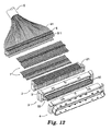
図12は、本発明の実施形態によるアダプタの分解斜視図であり、図13は、組み立てられた状態の、本発明の実施形態によるアダプタの斜視図である。 FIG. 12 is an exploded perspective view of an adapter according to an embodiment of the present invention, and FIG. 13 is a perspective view of the adapter according to an embodiment of the present invention in an assembled state.
コネクタ200とケーブル5により形成される、本発明の実施形態によるアダプタを、以下で説明する。
An adapter according to an embodiment of the present invention formed by the
本発明における、いわゆる「アダプタ」とは、ケーブル5をコネクタ200にはんだ付けすることにより形成される装置を意味することを、特記しなければならない。
It should be noted that the so-called “adapter” in the present invention means a device formed by soldering the
本発明の実施形態によるアダプタは、図12に示されるように、コネクタ200、複数の電線51を有するケーブル5、及び電線分離ブロック6を含む。
The adapter by embodiment of this invention contains the
電線分離ブロック6は、相互に間隔を離された複数の通路を有して形成され、複数の電線51がそれぞれ、通路を通って延ばされて、接点1のはんだ端子部分11の側面にはんだ付けされるようになっている。図12において、電線が電線分離ブロック6を通過する場所は、通路が形成されている場所である。
The electric wire separation block 6 is formed to have a plurality of passages spaced from each other, and a plurality of
本発明の実施形態においては、電線51が異なるゲージを有することがあるので、通路は、異なる断面積を有してもよい。それ故に、はんだスロット21は、異なるゲージの電線51に適合するように、異なる断面積を有してもよい。例えば、電線51の内の2本の電線が残りの電線よりも大きい直径を有するとき、より大きい直径を有する2本の電線に適合するために、通路の内の2つの通路は、残りの通路よりも大きい幅を有することになるであろうし、はんだスロット21の内の2つのはんだスロットは、残りの通路よりも大きい幅を有することになるであろう。
In embodiments of the present invention, the
あるいは、通路は、はんだスロット21に類似のスロットとして形成されて、異なる断面積を有することができる。
Alternatively, the passage can be formed as a slot similar to the
図12及び13を参照して、ケーブル5の電線51がコネクタ200にはんだ付けされるとき、電線51が、続いて及び対応して電線分離ブロック6の通路に分配され、すなわち、電線51がそれぞれ通路を通して挿入され、次に、それぞれの電線51の前側端部511が、それぞれのはんだスロット21内に置かれる。それぞれの電線51の前側端部511が、図4に示されるように、対応する接点1のはんだ端子部分11にはんだ付けされ、その結果、図13に示されるようなアダプタが得られる。
12 and 13, when the
本発明の実施形態により、端子デバイス100、コネクタ200、及びアダプタの製造能率が向上し、素早いはんだ付けが達成できる。加えて、上記のように、隣接するはんだ付けユニット21を絶縁するための分離リブ22が、隣接するはんだスロット21の間に形成されているので、隣接するはんだ付けユニットの間で短絡が発生するのを防止することができ、及びはんだ付けの高い信頼性を達成することができる。
According to the embodiment of the present invention, the manufacturing efficiency of the
実施形態が示されて説明されてきたが、その事実上の趣旨又は本質的な原理から逸脱することなく、本発明に対して変更をなし得ることを、当業者は理解するであろう。本発明の範囲内又は等価物の範囲内でなされる全ての変更が、本発明に包含される。 While embodiments have been shown and described, those skilled in the art will appreciate that changes can be made to the present invention without departing from its practical spirit or essential principles. All modifications made within the scope of the present invention or equivalents are included in the present invention.
Claims (33)
端子デバイスの表面内に形成されたはんだスロットを包含する絶縁体と、
本体部分及び前記本体部分の端部に形成されたはんだ端子部分を包含して、厚さよりも広い幅を有する接点と、を含み、
前記はんだ端子部分の幅方向が、前記はんだスロットの深さ方向に実質的に一致するように、前記はんだ端子部分が垂直に前記はんだスロット内に置かれる、端子デバイス。 A terminal device,
An insulator containing solder slots formed in the surface of the terminal device;
Including a body portion and a solder terminal portion formed at an end portion of the body portion, and a contact having a width wider than the thickness,
The terminal device, wherein the solder terminal portion is placed vertically in the solder slot such that the width direction of the solder terminal portion substantially coincides with the depth direction of the solder slot.
前記はんだスロットが、前記第一及び第二の表面の少なくとも一方に形成されている、請求項3に記載の端子デバイス。 The insulator includes a first surface and a second surface opposite the first surface;
The terminal device according to claim 3, wherein the solder slot is formed in at least one of the first and second surfaces.
前記接点のほぼ中心に位置する垂直部分により形成される保持部分と、
前記ねじり部分と前記保持部分の上側端部との間に位置する遷移部分と、
前記保持部分の下側端部に繋がる水平部分により形成される接点部分と、
を含む、請求項14に記載の端子デバイス。 The body portion further comprises:
A holding portion formed by a vertical portion located substantially in the center of the contact;
A transition portion located between the twisted portion and the upper end of the holding portion;
A contact portion formed by a horizontal portion connected to the lower end of the holding portion;
The terminal device according to claim 14, comprising:
前記保持部分の前記下側端部に繋がる弾性支持部と、
前記保持部分から離れた前記接点部分の自由端に形成された巻き付き接点部と、
前記弾性支持部と前記巻き付き接点部との間に位置して、上向きに突き出る、突出接点部と、
を含む、請求項17に記載の端子デバイス。 The contact portion is
An elastic support connected to the lower end of the holding portion;
A wound contact portion formed at a free end of the contact portion away from the holding portion;
A protruding contact portion located between the elastic support portion and the wound contact portion and protruding upward;
The terminal device according to claim 17, comprising:
表面に形成されたはんだスロットを包含する絶縁体を準備する工程と、
本体部分及び前記本体部分の端部に形成されたはんだ端子部分を包含して、厚さよりも広い幅を有する接点を準備する工程と、
前記はんだ端子部分の幅方向が前記はんだスロットの深さ方向に実質的に一致するように、前記はんだ端子部分を垂直に前記はんだスロット内に置く工程と、
を含む、方法。 A method of manufacturing a terminal device, comprising:
Providing an insulator including solder slots formed on the surface;
Including a body portion and a solder terminal portion formed at an end of the body portion, and preparing a contact having a width wider than the thickness;
Placing the solder terminal portion vertically in the solder slot such that the width direction of the solder terminal portion substantially coincides with the depth direction of the solder slot;
Including a method.
複数の電線を包含するケーブルと、
請求項27に記載のコネクタと、を含み、
前記複数の電線がそれぞれ、端部において、前記はんだスロット内の前記はんだ端子部分の側面にはんだ付けされている、アダプタ。 An adapter,
A cable including a plurality of electric wires;
A connector according to claim 27,
The adapter, wherein each of the plurality of electric wires is soldered at an end to a side surface of the solder terminal portion in the solder slot.
Applications Claiming Priority (2)
| Application Number | Priority Date | Filing Date | Title |
|---|---|---|---|
| CNA2007100914510A CN101276968A (en) | 2007-03-30 | 2007-03-30 | Connecting terminal apparatus, connector and adapter |
| PCT/US2008/055939 WO2008121485A1 (en) | 2007-03-30 | 2008-03-05 | Terminal device, connector and adaptor |
Publications (2)
| Publication Number | Publication Date |
|---|---|
| JP2010524154A true JP2010524154A (en) | 2010-07-15 |
| JP2010524154A5 JP2010524154A5 (en) | 2011-04-21 |
Family
ID=39808629
Family Applications (1)
| Application Number | Title | Priority Date | Filing Date |
|---|---|---|---|
| JP2010501043A Withdrawn JP2010524154A (en) | 2007-03-30 | 2008-03-05 | Terminal devices, connectors, and adapters |
Country Status (5)
| Country | Link |
|---|---|
| US (1) | US20100055992A1 (en) |
| EP (1) | EP2135329A1 (en) |
| JP (1) | JP2010524154A (en) |
| CN (1) | CN101276968A (en) |
| WO (1) | WO2008121485A1 (en) |
Families Citing this family (9)
| Publication number | Priority date | Publication date | Assignee | Title |
|---|---|---|---|---|
| TW200922009A (en) * | 2007-12-07 | 2009-05-16 | Jye Chuang Electronic Co Ltd | Contact terminal |
| JP2010257903A (en) * | 2009-04-28 | 2010-11-11 | Alps Electric Co Ltd | Connector |
| JP5212499B2 (en) * | 2010-09-08 | 2013-06-19 | 第一精工株式会社 | Electrical connector and manufacturing method thereof |
| CN103311775A (en) * | 2012-03-13 | 2013-09-18 | 贝尔威勒电子股份有限公司 | Connector terminal weld part forming method and structure |
| TWM551357U (en) * | 2017-04-06 | 2017-11-01 | 宣德科技股份有限公司 | Electrical connector |
| CN107453079B (en) * | 2017-07-18 | 2019-08-30 | 番禺得意精密电子工业有限公司 | Electric connector |
| CN107565229B (en) * | 2017-07-21 | 2020-06-09 | 番禺得意精密电子工业有限公司 | Electrical connector |
| CN107834317B (en) * | 2017-10-19 | 2024-03-29 | 王燕军 | Female connector, male connector and combination |
| JP7366717B2 (en) * | 2019-12-03 | 2023-10-23 | 日本航空電子工業株式会社 | connector assembly |
Family Cites Families (14)
| Publication number | Priority date | Publication date | Assignee | Title |
|---|---|---|---|---|
| JP2623435B2 (en) * | 1993-09-17 | 1997-06-25 | 日本航空電子工業株式会社 | Isometric right angle connector |
| JP3234856B2 (en) * | 1995-03-08 | 2001-12-04 | アルプス電気株式会社 | Connector pin contact and method of manufacturing the same |
| JPH08250167A (en) * | 1995-03-08 | 1996-09-27 | Alps Electric Co Ltd | Connector for pc card |
| JP3286185B2 (en) * | 1996-10-21 | 2002-05-27 | アルプス電気株式会社 | Socket connector contact structure |
| JPH11195459A (en) * | 1998-01-05 | 1999-07-21 | Itabashi Giken Kk | Connector |
| JPH11288771A (en) * | 1998-03-31 | 1999-10-19 | Mitsumi Electric Co Ltd | Connector |
| TW385092U (en) * | 1998-12-28 | 2000-03-11 | Hon Hai Prec Ind Co Ltd | Electrical connectors |
| US6217348B1 (en) * | 1999-08-09 | 2001-04-17 | Hon Hai Precision Ind. Co., Ltd. | Electrical connector |
| US6572397B2 (en) * | 2001-10-09 | 2003-06-03 | Lotes Co., Ltd. | Structure of a ball grid array IC socket connection with solder ball |
| TWI290391B (en) * | 2004-08-06 | 2007-11-21 | Top Yang Technology Entpr Co | Electrical connector with a solder ball locking structure and method for manufacturing the same |
| US7128622B2 (en) * | 2004-10-20 | 2006-10-31 | Chou Hsuan Tsai | Electrical connector with a solder ball locking structure |
| US7147489B1 (en) * | 2005-10-12 | 2006-12-12 | Tai Twun Enterprise Co., Ltd. | Socket having a structure for grasping solder balls |
| CN201222553Y (en) * | 2008-07-01 | 2009-04-15 | 番禺得意精密电子工业有限公司 | Electric connector |
| TWM373039U (en) * | 2009-07-17 | 2010-01-21 | Hon Hai Prec Ind Co Ltd | Electrical connector and contacts thereof |
-
2007
- 2007-03-30 CN CNA2007100914510A patent/CN101276968A/en active Pending
-
2008
- 2008-03-05 US US12/531,712 patent/US20100055992A1/en not_active Abandoned
- 2008-03-05 EP EP08731458A patent/EP2135329A1/en not_active Withdrawn
- 2008-03-05 JP JP2010501043A patent/JP2010524154A/en not_active Withdrawn
- 2008-03-05 WO PCT/US2008/055939 patent/WO2008121485A1/en active Application Filing
Also Published As
| Publication number | Publication date |
|---|---|
| EP2135329A1 (en) | 2009-12-23 |
| US20100055992A1 (en) | 2010-03-04 |
| WO2008121485A1 (en) | 2008-10-09 |
| CN101276968A (en) | 2008-10-01 |
Similar Documents
| Publication | Publication Date | Title |
|---|---|---|
| JP2010524154A (en) | Terminal devices, connectors, and adapters | |
| TWI437766B (en) | Electrical connector and method to reduce arcing between mounting terminals of power | |
| TW510072B (en) | Micro connector assembly and method of making the same | |
| US9401550B2 (en) | Connector | |
| US8109783B2 (en) | Insulation displacement connector (IDC) | |
| CN112086780B (en) | Sandwich type electric connector | |
| US9077101B2 (en) | Cable assembly | |
| US8052464B2 (en) | Connector | |
| JP3161828U (en) | Electrical connector and conductive terminal thereof | |
| EP3007276B1 (en) | Single element connector | |
| KR20110022569A (en) | Electric connector | |
| US7837514B2 (en) | Electrical connectors with vertically oriented contacts | |
| JPWO2008120632A1 (en) | Connector terminal and connector provided with the connector terminal | |
| US8992247B2 (en) | Multi-surface contact plug assemblies, systems and methods | |
| EP2040337B1 (en) | Electrical connector | |
| TWI496359B (en) | Lead frame, method of manufacturing a contact group, and connector | |
| JP2006210206A (en) | Connector and portable terminal | |
| CN109193216B (en) | Electric connector and electric connector combination thereof | |
| JP2024086986A (en) | Terminal Pair | |
| US8308499B2 (en) | Duplex profile connector assembly having retention means for assembling upper and lower connectors thereof together | |
| US10505299B2 (en) | Electrical connector having an improved metal shell with a soldering portion | |
| US9325081B2 (en) | Cable connector with low impedance | |
| TWM481515U (en) | Electrical connector | |
| CN201639020U (en) | Electric connector | |
| JP2007123104A (en) | Connector for coaxial cable |
Legal Events
| Date | Code | Title | Description |
|---|---|---|---|
| A521 | Request for written amendment filed |
Free format text: JAPANESE INTERMEDIATE CODE: A523 Effective date: 20110225 |
|
| A621 | Written request for application examination |
Free format text: JAPANESE INTERMEDIATE CODE: A621 Effective date: 20110225 |
|
| A761 | Written withdrawal of application |
Free format text: JAPANESE INTERMEDIATE CODE: A761 Effective date: 20111205 |

