JP2010518924A - Measuring device for physiological parameters - Google Patents
Measuring device for physiological parameters Download PDFInfo
- Publication number
- JP2010518924A JP2010518924A JP2009550212A JP2009550212A JP2010518924A JP 2010518924 A JP2010518924 A JP 2010518924A JP 2009550212 A JP2009550212 A JP 2009550212A JP 2009550212 A JP2009550212 A JP 2009550212A JP 2010518924 A JP2010518924 A JP 2010518924A
- Authority
- JP
- Japan
- Prior art keywords
- measuring device
- chamber
- fluid
- measuring
- fluid chamber
- Prior art date
- Legal status (The legal status is an assumption and is not a legal conclusion. Google has not performed a legal analysis and makes no representation as to the accuracy of the status listed.)
- Pending
Links
- 239000012530 fluid Substances 0.000 claims abstract description 89
- 210000004556 brain Anatomy 0.000 claims abstract description 45
- 239000012528 membrane Substances 0.000 claims abstract description 22
- 238000007789 sealing Methods 0.000 claims abstract description 11
- 238000005259 measurement Methods 0.000 claims description 27
- 239000000523 sample Substances 0.000 claims description 12
- 239000000463 material Substances 0.000 claims description 5
- 229910052751 metal Inorganic materials 0.000 claims description 5
- 239000002184 metal Substances 0.000 claims description 5
- 229920001296 polysiloxane Polymers 0.000 claims description 4
- 239000004696 Poly ether ether ketone Substances 0.000 claims description 3
- 239000004033 plastic Substances 0.000 claims description 3
- 229920002530 polyetherether ketone Polymers 0.000 claims description 3
- 230000013011 mating Effects 0.000 claims 1
- 238000004519 manufacturing process Methods 0.000 abstract description 3
- 210000003625 skull Anatomy 0.000 description 7
- 229910001069 Ti alloy Inorganic materials 0.000 description 3
- RTAQQCXQSZGOHL-UHFFFAOYSA-N Titanium Chemical compound [Ti] RTAQQCXQSZGOHL-UHFFFAOYSA-N 0.000 description 3
- 230000005540 biological transmission Effects 0.000 description 3
- 238000011156 evaluation Methods 0.000 description 3
- 210000004761 scalp Anatomy 0.000 description 3
- 239000010936 titanium Substances 0.000 description 3
- 229910052719 titanium Inorganic materials 0.000 description 3
- 210000000683 abdominal cavity Anatomy 0.000 description 2
- 230000000694 effects Effects 0.000 description 2
- 238000005086 pumping Methods 0.000 description 2
- 238000004026 adhesive bonding Methods 0.000 description 1
- 238000009530 blood pressure measurement Methods 0.000 description 1
- 230000002490 cerebral effect Effects 0.000 description 1
- 238000003780 insertion Methods 0.000 description 1
- 230000037431 insertion Effects 0.000 description 1
- 230000009347 mechanical transmission Effects 0.000 description 1
- 230000002093 peripheral effect Effects 0.000 description 1
Images

Classifications
-
- A—HUMAN NECESSITIES
- A61—MEDICAL OR VETERINARY SCIENCE; HYGIENE
- A61B—DIAGNOSIS; SURGERY; IDENTIFICATION
- A61B5/00—Measuring for diagnostic purposes; Identification of persons
- A61B5/03—Measuring fluid pressure within the body other than blood pressure, e.g. cerebral pressure ; Measuring pressure in body tissues or organs
- A61B5/031—Intracranial pressure
-
- A—HUMAN NECESSITIES
- A61—MEDICAL OR VETERINARY SCIENCE; HYGIENE
- A61B—DIAGNOSIS; SURGERY; IDENTIFICATION
- A61B5/00—Measuring for diagnostic purposes; Identification of persons
- A61B5/0002—Remote monitoring of patients using telemetry, e.g. transmission of vital signals via a communication network
- A61B5/0004—Remote monitoring of patients using telemetry, e.g. transmission of vital signals via a communication network characterised by the type of physiological signal transmitted
- A61B5/0008—Temperature signals
-
- A—HUMAN NECESSITIES
- A61—MEDICAL OR VETERINARY SCIENCE; HYGIENE
- A61B—DIAGNOSIS; SURGERY; IDENTIFICATION
- A61B5/00—Measuring for diagnostic purposes; Identification of persons
- A61B5/0002—Remote monitoring of patients using telemetry, e.g. transmission of vital signals via a communication network
- A61B5/0031—Implanted circuitry
-
- A—HUMAN NECESSITIES
- A61—MEDICAL OR VETERINARY SCIENCE; HYGIENE
- A61B—DIAGNOSIS; SURGERY; IDENTIFICATION
- A61B5/00—Measuring for diagnostic purposes; Identification of persons
- A61B5/68—Arrangements of detecting, measuring or recording means, e.g. sensors, in relation to patient
- A61B5/6846—Arrangements of detecting, measuring or recording means, e.g. sensors, in relation to patient specially adapted to be brought in contact with an internal body part, i.e. invasive
- A61B5/6847—Arrangements of detecting, measuring or recording means, e.g. sensors, in relation to patient specially adapted to be brought in contact with an internal body part, i.e. invasive mounted on an invasive device
- A61B5/6864—Burr holes
-
- A—HUMAN NECESSITIES
- A61—MEDICAL OR VETERINARY SCIENCE; HYGIENE
- A61B—DIAGNOSIS; SURGERY; IDENTIFICATION
- A61B5/00—Measuring for diagnostic purposes; Identification of persons
- A61B5/68—Arrangements of detecting, measuring or recording means, e.g. sensors, in relation to patient
- A61B5/6846—Arrangements of detecting, measuring or recording means, e.g. sensors, in relation to patient specially adapted to be brought in contact with an internal body part, i.e. invasive
- A61B5/6847—Arrangements of detecting, measuring or recording means, e.g. sensors, in relation to patient specially adapted to be brought in contact with an internal body part, i.e. invasive mounted on an invasive device
- A61B5/6865—Access ports
Landscapes
- Health & Medical Sciences (AREA)
- Life Sciences & Earth Sciences (AREA)
- Engineering & Computer Science (AREA)
- Medical Informatics (AREA)
- Surgery (AREA)
- Biophysics (AREA)
- Pathology (AREA)
- Veterinary Medicine (AREA)
- Biomedical Technology (AREA)
- Heart & Thoracic Surgery (AREA)
- Public Health (AREA)
- Molecular Biology (AREA)
- Physics & Mathematics (AREA)
- Animal Behavior & Ethology (AREA)
- General Health & Medical Sciences (AREA)
- Computer Networks & Wireless Communication (AREA)
- Neurosurgery (AREA)
- Hematology (AREA)
- Physiology (AREA)
- Measuring And Recording Apparatus For Diagnosis (AREA)
- External Artificial Organs (AREA)
Abstract
脳液を収容する埋込み可能な流体チャンバと、流体チャンバ内の前記脳液と膜を介して連絡し、1つ又は複数の生理学的パラメータ用センサ、前記センサの信号を無線送信するための電子部品、及びテレメトリ装置を含むセンサ装置とを備えた生理学的パラメータ用測定装置であって、製造及び取扱いを改良するために、前記流体チャンバが少なくとも2つのハウジング部分を含み、これら2つのハウジング部分は、閉鎖内部を形成すべく、密封するやり方で嵌合されるように適合されており、嵌合しないときは前記内部へのアクセスを許容すること、及び、前記センサ装置が、全面が閉じた測定チャンバ内に配置されており、この測定チャンバが、独立した取扱いに適合された部品として構成され、かつ、前記流体チャンバの前記内部の規定の位置に挿入可能であることが提案される。 An implantable fluid chamber containing brain fluid, and the brain fluid in the fluid chamber through the membrane, one or more physiological parameter sensors, and electronic components for wirelessly transmitting the sensor signals And a physiological parameter measuring device comprising a telemetry device, wherein the fluid chamber comprises at least two housing parts for improved manufacturing and handling, the two housing parts comprising: A measuring chamber which is adapted to be fitted in a sealing manner to form a closed interior, allowing access to the interior when not fitted, and the sensor device is entirely closed The measuring chamber is configured as a part adapted for independent handling and the internal regulation of the fluid chamber. It is proposed to position is insertable.
Description
本発明は、脳液を収容する埋込み可能な流体チャンバと、前記流体チャンバ内の脳液と膜を介して連絡し、かつ、1つ又は複数の生理学的パラメータ用センサ、前記センサの信号を無線送信するための電子部品、及びテレメトリ装置を含むセンサ装置とを備えた生理学的パラメータ用測定装置に関する。 The present invention relates to an implantable fluid chamber containing brain fluid, communicating with the brain fluid in the fluid chamber through a membrane, and wirelessly transmitting one or more physiological parameter sensors, the signals of the sensors. The invention relates to a physiological parameter measuring device comprising an electronic component for transmission and a sensor device including a telemetry device.
このような測定装置が、例えばWO2006/117123A1に記載されている。このような測定装置は通常、頭蓋骨の外側で頭皮の真下の、ある場合には頭蓋冠内の穿孔の上方に直接埋込まれ、別の場合にはこのような穿孔(脳液が頭蓋の内側から流体チャンバに入ることができる)に隣接して埋込まれている。既に知られているこの測定装置では、流体チャンバは、中間壁により2つの区画に分割されている二重チャンバとして構成されており、これら区画のうちの一方はセンサ装置を収容し、他方の区画は脳液が流通する。区画間の中間壁には膜が配置されており、この膜を通して脳液の圧力がセンサ装置の圧力センサに伝達される。 Such a measuring device is described in, for example, WO2006 / 117123A1. Such measuring devices are usually implanted directly outside the skull, directly under the scalp, in some cases directly above the perforations in the calvaria, and in other cases such perforations (where brain fluid is inside the skull). Embedded in the fluid chamber). In this known measuring device, the fluid chamber is configured as a double chamber divided into two compartments by an intermediate wall, one of these compartments containing the sensor device and the other compartment Circulates brain fluid. A membrane is disposed on the intermediate wall between the compartments, and the pressure of the brain fluid is transmitted to the pressure sensor of the sensor device through this membrane.
このような組立品は予め全体として作製されねばならず、封止的に密封されねばならない。従って故障した場合、全部交換することしかできない。更に、製造が複雑である。 Such an assembly must be made in advance as a whole and must be hermetically sealed. Therefore, if it fails, it can only be replaced. Furthermore, the manufacturing is complicated.
本発明の目的は、製造が簡素化されるように、かつ、測定装置全体を交換しなくても必要に応じて修理作業を実行できるように、包括的な測定装置を構築することである。 It is an object of the present invention to build a comprehensive measuring device so that manufacturing is simplified and repair work can be performed as needed without having to replace the entire measuring device.
この目的は、本発明によれば、冒頭で記載されている種類の測定装置において、前記流体チャンバが少なくとも2つのハウジング部分を含み、該2つのハウジング部分は、閉鎖内部を形成すべく、密封するやり方で嵌合されるように適合されており、嵌合しないときは前記内部へのアクセスを許容すること、及び、前記センサ装置が、全面が閉じた測定チャンバ内に配置されており、該測定チャンバが、独立した取扱いに適合された部品として構成され、かつ、前記流体チャンバの前記内部の規定の位置に挿入可能であることにより達成される。 This object is achieved according to the invention in a measuring device of the kind described at the outset, wherein the fluid chamber comprises at least two housing parts, which are sealed to form a closed interior. Adapted to be mated in a manner, allowing access to the interior when not mated, and the sensor device being arranged in a measurement chamber which is completely closed This is achieved by the fact that the chamber is configured as a part adapted for independent handling and can be inserted into a defined position inside the fluid chamber.
前記測定チャンバが独立して取扱い可能な部品として構成されるため、前記流体チャンバの開放された前記内部に挿入することができ、その際、前記内部の規定の位置に保持される。前記流体チャンバの前記少なくとも2つのハウジング部分を接合することにより、前記流体チャンバは外側に対してしっかりと密封することができるが、必要に応じて再度開くこともできる。このため、前記測定チャンバは取り出すことができ、前記流体チャンバを交換しなくても、必要に応じて交換することができる。前記センサ装置が故障した場合でも、前記流体チャンバは依然としてその埋込み位置に留まってよいので、新規の測定チャンバを挿入した後に使用を継続することができる。 Since the measuring chamber is configured as an independently handleable part, it can be inserted into the open interior of the fluid chamber, while being held in a defined position within the interior. By joining the at least two housing portions of the fluid chamber, the fluid chamber can be tightly sealed to the outside, but can also be reopened as needed. For this reason, the measurement chamber can be taken out, and can be replaced as needed without replacing the fluid chamber. Even if the sensor device fails, the fluid chamber may still remain in its implanted position and can continue to be used after inserting a new measurement chamber.
従って外科医は、手術が進行し、容易でない前記流体チャンバの埋込みを終了して初めて、前記測定チャンバを挿入するという可能性をも有する。このことは手術を容易にし、しかも手術中、前記感度の良いセンサ装置に優しい。 Thus, the surgeon also has the possibility of inserting the measurement chamber only after the operation has progressed and the fluid chamber has not been easily implanted. This facilitates the operation and is friendly to the sensitive sensor device during the operation.
前記内部が少なくとも1つの入口を介してプローブに接続されており、前記プローブを介して、脳液が脳の測定点から前記内部に流れ込むことができることは好都合である。更に、前記内部が脳液の少なくとも1つの出口を有するようにしてもよい。その場合、前記流体チャンバはシャント系の一部であり、脳液は前記シャント系により、それ自体知られているやり方で、脳から、例えば排液パイプを通して腹腔へと排出することができる。 Conveniently, the interior is connected to a probe via at least one inlet, through which brain fluid can flow from the measurement point of the brain into the interior. Furthermore, the interior may have at least one outlet for brain fluid. In that case, the fluid chamber is part of a shunt system, and brain fluid can be drained by the shunt system from the brain, for example through a drainage pipe, into the abdominal cavity in a manner known per se.
好適な実施形態において、前記流体チャンバが、底部及び隣接する側壁を備えた第1ハウジング部分と、前記第1ハウジング部分上に密封するやり方で置かれるように適合されたカバーとして構成されている第2ハウジング部分とを含むようになっている。 In a preferred embodiment, the fluid chamber is configured as a first housing part with a bottom and an adjacent side wall and a cover adapted to be placed in a sealing manner on the first housing part. 2 housing parts.
前記流体チャンバの前記壁の1つの領域が可撓性を有するように構成され、前記壁の残りの領域が剛性を有するように構成されると特に有利である。このようにして前記可撓壁領域を押し込むことにより、前記流体チャンバ内の前記脳液に圧力パルスを伝達することができる。この圧力パルスはポンピングパルスとして作用することができ、従って例えば流路が汚染したり詰まったりした場合に清浄をもたらす。もっとも、前記圧力パルスを使用して、例えば前記センサの制御信号を生成し、これによって前記センサが機能しているかどうかを点検するようにしてもよい。 It is particularly advantageous if one region of the wall of the fluid chamber is configured to be flexible and the remaining region of the wall is configured to be rigid. By pushing the flexible wall region in this way, a pressure pulse can be transmitted to the brain fluid in the fluid chamber. This pressure pulse can act as a pumping pulse, thus providing a clean if, for example, the flow path is contaminated or clogged. However, the pressure pulse may be used, for example, to generate a control signal for the sensor, thereby checking whether the sensor is functioning.
特に、前記可撓壁領域は、可撓膜、例えばシリコーン製の可撓膜により形成することができる。 In particular, the flexible wall region can be formed by a flexible film, for example, a flexible film made of silicone.
このような構成は、シリコーン製又は同様の材料製のこのような可撓膜を通して、前記流体チャンバの前記内部に前記流体の試料を除去するためのカニューレを導入することができるという更なる利点を有する。このようにして、前記測定装置が埋込まれている場合であっても、頭皮及び前記可撓膜を通して前記脳液にアクセスすることができる。 Such a configuration has the further advantage that a cannula for removing a sample of the fluid can be introduced into the interior of the fluid chamber through such a flexible membrane made of silicone or similar material. Have. In this way, even when the measuring device is implanted, the brain fluid can be accessed through the scalp and the flexible membrane.
好適な実施形態によれば、前記可撓膜は、第2ハウジング部分と嵌合することで前記流体チャンバを形成するように適合されたハウジング部分を前記膜と共に形成する密封リングに挿入されるようにしてもよい。例えばこの密封リングは、前記第2ハウジング部分に密封するやり方でねじ込まれてもよい。 According to a preferred embodiment, the flexible membrane is inserted into a sealing ring that forms a housing portion with the membrane adapted to mate with a second housing portion to form the fluid chamber. It may be. For example, the sealing ring may be screwed in a manner that seals to the second housing part.
特に、前記流体チャンバの可撓壁領域を備えた構成において、前記測定チャンバが、脳液により全面が包囲されるよう、前記流体チャンバに挿入されると有利である。これによって、前記脳液は前記可撓壁領域のすぐ近くの前記内部の部分をも流通するので、前記可撓壁領域の助けを得てポンピングの可能性が改良される。 In particular, in a configuration with a flexible wall region of the fluid chamber, it is advantageous if the measurement chamber is inserted into the fluid chamber so that the entire surface is surrounded by brain fluid. As a result, the brain fluid also flows through the internal part in the immediate vicinity of the flexible wall region, so that the possibility of pumping is improved with the help of the flexible wall region.
好ましくは、前記測定チャンバは金属、例えばチタン又はチタン合金から成り、前記測定チャンバが剛性壁を有すると好都合である。もっとも、前記壁は比較的薄くてもよく、例えば、壁厚は10分の数ミリメートルのオーダーである。 Preferably, the measuring chamber is made of a metal, such as titanium or a titanium alloy, and it is convenient if the measuring chamber has a rigid wall. However, the wall may be relatively thin, for example, the wall thickness is on the order of a few tenths of a millimeter.
前記流体チャンバは、人体に適合性のある金属、例えばチタン又はチタン合金から成るようにしてもよい。もっとも、前記流体チャンバを、殺菌可能なプラスチック材料、例えばポリエーテルエーテルケトンから作ることも可能である。プラスチック材料を使用することは、前記測定チャンバの前記内部にある前記テレメトリ装置の遮蔽効果(前記流体チャンバが金属で構築される場合に存在するものであり、前記信号の送信を妨害する)が排除される、という利点を有する。 The fluid chamber may be made of a metal compatible with the human body, such as titanium or a titanium alloy. However, it is also possible to make the fluid chamber from a sterilizable plastic material such as polyetheretherketone. The use of plastic material eliminates the shielding effect of the telemetry device inside the measurement chamber (which exists when the fluid chamber is constructed of metal and interferes with the transmission of the signal). Has the advantage of being
より詳細な説明として、本発明の好適な実施形態を、図面と合わせて以下に記載する。 For a more detailed description, preferred embodiments of the present invention are described below in conjunction with the drawings.
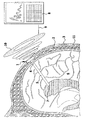
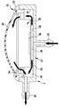
図面に示す測定装置1は通常、頭蓋骨2の外側で頭皮3の真下の、穿孔4の上方に埋込まれ、又はこのような穿孔に隣接して埋込まれる。プローブ5又はカテーテルが、穿孔4を通過して脳6の内側に入り、入口点7で終端しており、入口点7では脳6からの脳液がプローブ5に入ることができる。この脳液がプローブ5により測定装置1に送り込まれ、測定装置1では、脳液の生理値、例えば脳液の圧力及び/又は温度を測定することができる。
The
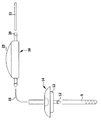
測定装置1においてこのようにして記録された生理学的パラメータの測定値は、無線式に測定線9によってコイル10に接続している外部評価装置に送信される。このコイル10は、測定装置の対応するコイルと無線式に信号を交換できるように測定装置1付近に配置することができる。これらのコイルを介して、測定装置1に外部電源を供給することもできる。
The measured values of the physiological parameters recorded in this way in the
測定装置1に送り込まれた脳液は、排液パイプ11を通して排出することができる。このような排液パイプは、例えば患者の腹腔で終端している。従ってプローブ5、測定装置1、及び排液パイプ11は、頭蓋から脳液を除去することのできるシャント系を形成する。
The brain fluid sent to the
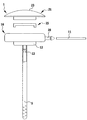
測定装置1が穿孔4の真上に置かれている場合、測定装置1がその下面に、穿孔4に入る突起12と、隣接する接続部13とを有することは好都合である。接続部13は例えば、可撓性の線14によりプローブ5に接続することができ(図2)、又は、接続部13上にプローブ5を直接押し付けることができる(図11)。
When the measuring
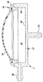
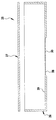
対照的に、測定装置1が穿孔4に隣接して配置される場合、穿孔カバー14を設けることが有利である。穿孔カバー14もその下面で突起12及び接続部13を担持し、頭蓋骨に対して平行に脳液を逸らすので、脳液は更なる線15を通って傍にある測定装置1に入る(図3)。
In contrast, if the measuring
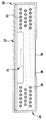
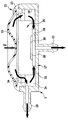
測定装置1は、平坦な底部18と、外側で隣接する垂直な壁19とを有する缶状基部17を備えている流体チャンバ16を含む。好ましくは、この缶状基部17は円形断面を有する。図4及び図5に示す実施形態において、底部18は、脳液が進入するための下方に向かう接続部13と、脳液が排出するための壁19から水平に延びる出口20とを有する。
The measuring
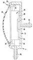
缶状基部17は上側が開き、そこでは蓋状ハウジング部分21により缶状基部をしっかりと閉じることができる。この蓋状ハウジング部分21は、リング22を含む。リング22は密封リングとして構成されており、例えばねじ込むか中で接着することにより、密封するように基部17の壁19に接続可能である。リング22には、フード状可撓膜23が密封するやり方で挿入される。好ましくは、フード状可撓膜23はシリコーンから成るのに対して、リング22は例えばポリエーテルエーテルケトンから成るようにしてもよい。底部状基部17と蓋状ハウジング部分21は、嵌合すると、内部24を備えたハウジング様の流体チャンバを形成する。内部24は、接続部13及び出口20を除いて閉じている。埋込み状態のとき、この内部24を脳液が流通し、内部を完全に膨らませる。これによって可撓膜23は、図9に示すやり方で外方へ弓形になる。
The can-like
この可撓膜は図10に示すように、膜23への圧力により内方に押し込むことができる。これによって脳液は、内部24から出口20と接続部13の双方を通って、流体チャンバ16から追い出される。即ち、プローブ5の逆迸出が起こり、排液パイプ11は迸出が増加する。この迸出効果を使って対応するパイプを清浄してもよいが、可撓膜23へのこの圧力によって圧力パルスを脳液へ送信することもでき、圧力パルスは測定装置1により記録することができる。これによって、測定装置が機能しているかどうかを点検することが可能である。
This flexible membrane can be pushed inward by pressure on the
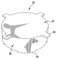
内部24には、完全に封鎖された同様に缶状であり円形断面を有する基部26と、密封するやり方でこの基部26に置かれるカバー27とを含む測定チャンバ25が挿入される(図7)。好ましくは、この測定チャンバは、金属、特にチタン又はチタン合金から成る。壁は、基部26の底部29の中央領域28を除いて剛性に構成される。この領域では、可撓膜30が挿入されるか、又は、材料を除去したおかげで、底部29が、可撓膜30を形成するように薄く構成される。
Inserted into the interior 24 is a
測定チャンバ25の内部には、センサチップ31と、このセンサチップを包囲するコイル32とが収容されている。センサチップ31は、少なくとも1つのセンサ、例えば圧力センサ及び/又は温度センサと、更に、これらのセンサにより生成される電気信号を処理しディジタル化すると共に電力を供給するための電子部品と、センサにより生成される信号をコイル32を介して外部へ送信するテレメトリ回路の電子部品を担持する。次に、これらの信号は、外部評価装置8のコイル10により受信することができる。
A
測定チャンバ25の内部には、圧力伝達媒体、例えば空気、油、又はゲルが充填されている。可撓膜30とセンサチップ31上のセンサとの間に、機械的伝達部材、例えばピストン又はレバーを設けることも可能である。脳液の圧力が可撓膜30を介してセンサチップ31上のセンサに達し、対応する測定信号をそこで生成できることのみが肝要である。
The
測定チャンバ25はその下端にて、周縁部の一部を越えて延び、下方に突出する支持突起33を担持しており、カバー27上には、放射状に突き出す心出しウェブ34を担持しているので、測定チャンバ25は、流体チャンバ16の基部17に挿入される際、正確に規定された位置に配置される。その際、支持突起33は基部17の底部18上で支持され、放射状の心出しウェブ34は、基部17の壁19上で、又は流体チャンバが閉じた後にはリング22上で支持される。いずれにしても、この配置構成により、脳液が測定チャンバ25の周り全てを流れることができる、即ち、測定チャンバ25が、底部18及び壁19から、ならびに蓋状ハウジング部分21からも全体にわたって離間しているので、脳液が妨害されずにこれらの空間を流通できることが確実になる。
The
このことは、逆迸出パルス又は圧力パルスを可撓膜23によって脳液に送信する際に特に重要であるが、脳液が内部24を自由に流通できる結果として、圧力測定が歪曲されないことも重要である。
This is particularly important when a reverse ejection pulse or pressure pulse is transmitted to the brain fluid by the
流体チャンバ16が埋込まれた後、流体チャンバ16に測定チャンバ25を挿入することができる。測定チャンバが故障した場合、又はその他の測定が対象となる場合、測定チャンバを交換することも容易に可能となる。
After the
Claims (14)
前記流体チャンバ(16)内の前記脳液と膜(23)を介して連絡し、かつ、1つ又は複数の生理学的パラメータ用センサ、前記センサの信号を無線送信するための電子部品、及びテレメトリ装置を含むセンサ装置(31、32)と、
を備えた生理学的パラメータ用測定装置(1)であって、
前記流体チャンバ(16)が少なくとも2つのハウジング部分(17、21)を含み、該2つのハウジング部分(17、21)は、閉鎖内部(24)を形成すべく、密封するやり方で嵌合されるように適合されており、嵌合しないときは前記内部(24)へのアクセスを許容すること、及び、
前記センサ装置(31、32)が、全面が閉じた測定チャンバ(25)内に配置されており、該測定チャンバ(25)が、独立した取扱いに適合された部品として構成され、かつ、前記流体チャンバ(16)の前記内部(24)の規定の位置に挿入可能であること、
を特徴とする測定装置。 An implantable fluid chamber (16) containing brain fluid;
One or more physiological parameter sensors in communication with the brain fluid in the fluid chamber (16) through the membrane (23), electronic components for wirelessly transmitting the sensor signals, and telemetry A sensor device (31, 32) comprising the device;
A physiological parameter measuring device (1) comprising:
The fluid chamber (16) includes at least two housing parts (17, 21), the two housing parts (17, 21) being fitted in a sealing manner to form a closed interior (24). And adapted to allow access to the interior (24) when not mated; and
The sensor device (31, 32) is arranged in a measurement chamber (25) which is entirely closed, the measurement chamber (25) being configured as a part adapted for independent handling, and the fluid Being insertable into a defined position in the interior (24) of the chamber (16);
Measuring device characterized by.
Applications Claiming Priority (2)
| Application Number | Priority Date | Filing Date | Title |
|---|---|---|---|
| DE102007008642A DE102007008642B3 (en) | 2007-02-22 | 2007-02-22 | Measuring device for physiological parameters |
| PCT/EP2008/000039 WO2008101563A1 (en) | 2007-02-22 | 2008-01-05 | Measurement device for physiological parameters |
Publications (1)
| Publication Number | Publication Date |
|---|---|
| JP2010518924A true JP2010518924A (en) | 2010-06-03 |
Family
ID=39272215
Family Applications (1)
| Application Number | Title | Priority Date | Filing Date |
|---|---|---|---|
| JP2009550212A Pending JP2010518924A (en) | 2007-02-22 | 2008-01-05 | Measuring device for physiological parameters |
Country Status (8)
| Country | Link |
|---|---|
| US (1) | US20100030103A1 (en) |
| EP (1) | EP2120690B1 (en) |
| JP (1) | JP2010518924A (en) |
| CN (1) | CN101621962A (en) |
| AT (1) | ATE525015T1 (en) |
| DE (1) | DE102007008642B3 (en) |
| ES (1) | ES2369804T3 (en) |
| WO (1) | WO2008101563A1 (en) |
Cited By (2)
| Publication number | Priority date | Publication date | Assignee | Title |
|---|---|---|---|---|
| JP2014176663A (en) * | 2013-03-13 | 2014-09-25 | Depuy Synthes Products Llc | Docking station for remote measurement |
| JP2017181493A (en) * | 2016-03-28 | 2017-10-05 | オリオン バイオテック インコーポレイテッド | Wireless pressure sensor |
Families Citing this family (15)
| Publication number | Priority date | Publication date | Assignee | Title |
|---|---|---|---|---|
| DE102008030942A1 (en) | 2008-07-02 | 2010-01-07 | Christoph Miethke Gmbh & Co Kg | Cerebrospinal fluid drainage |
| DE102009060533B4 (en) * | 2009-12-23 | 2019-07-11 | Christoph Miethke Gmbh & Co Kg | Implantable shunt system |
| EP2629660B1 (en) * | 2010-10-22 | 2020-07-15 | C.Miethke GmbH&Co Kg | Implant for measuring the intracorporeal pressure, featuring telemetric transmission of measured values |
| US10675451B2 (en) | 2010-10-22 | 2020-06-09 | Christoph Miethke Gmbh & Co Kg | Hydrocephalus shunt arrangement and components thereof for draining cerebrospinal fluid in a patient having hydrocephalus |
| EP2672891B1 (en) * | 2011-02-08 | 2016-01-06 | Board of Trustees of the University of Arkansas | Pneumatic tocodynamometer |
| CN103491862B (en) * | 2011-02-16 | 2016-04-20 | 艾尔弗雷德·伊·曼科学研究基金会 | Implantable separate system and the pressure transducer be associated |
| US9901268B2 (en) | 2011-04-13 | 2018-02-27 | Branchpoint Technologies, Inc. | Sensor, circuitry, and method for wireless intracranial pressure monitoring |
| US9126009B2 (en) | 2013-03-12 | 2015-09-08 | DePuy Synthes Products, Inc. | System and method for determining position and pressure of an implantable shunt |
| US9962084B2 (en) * | 2013-06-15 | 2018-05-08 | Purdue Research Foundation | Wireless interstitial fluid pressure sensor |
| CN204428024U (en) * | 2014-01-20 | 2015-07-01 | 成都信息工程学院 | Implanted intracranial pressure wireless monitoring device |
| WO2015161102A1 (en) * | 2014-04-17 | 2015-10-22 | Branchpoint Technologies, Inc. | Wireless intracranial monitoring system |
| US9901269B2 (en) | 2014-04-17 | 2018-02-27 | Branchpoint Technologies, Inc. | Wireless intracranial monitoring system |
| CN104825150A (en) * | 2015-05-07 | 2015-08-12 | 复旦大学附属华山医院 | Intracranial disease monitoring and treating device |
| WO2017065881A1 (en) * | 2015-10-16 | 2017-04-20 | Branchpoint Technologies, Inc. | Wireless intracranial monitoring system |
| US11701504B2 (en) * | 2020-01-17 | 2023-07-18 | California Institute Of Technology | Implantable intracranial pressure sensor |
Citations (7)
| Publication number | Priority date | Publication date | Assignee | Title |
|---|---|---|---|---|
| US4385636A (en) * | 1978-05-23 | 1983-05-31 | Cosman Eric R | Telemetric differential pressure sensor with the improvement of a conductive shorted loop tuning element and a resonant circuit |
| US4660568A (en) * | 1976-06-21 | 1987-04-28 | Cosman Eric R | Telemetric differential pressure sensing system and method therefore |
| JPH03141924A (en) * | 1990-10-19 | 1991-06-17 | Japan Medical Dynamic Marketing Inc | Ventricle shunt also capable of measuring cranium inner pressure |
| JPH05300941A (en) * | 1992-04-28 | 1993-11-16 | Japan Medical Dynamic Marketing Inc | Method for checking flow rate of shunt valve in cerebral ventricle shunt |
| US20040050168A1 (en) * | 2000-07-08 | 2004-03-18 | Andreas Uberreiter | System elements for measuring pressure in extracorporeal circuits |
| JP2006255422A (en) * | 2005-03-15 | 2006-09-28 | Codman & Shurtleff Inc | Pressure sensitive instrument |
| WO2006117123A1 (en) * | 2005-04-30 | 2006-11-09 | Aesculap Ag & Co. Kg | Implantable device for recording intracranial pressures |
Family Cites Families (5)
| Publication number | Priority date | Publication date | Assignee | Title |
|---|---|---|---|---|
| US3943915A (en) * | 1974-11-29 | 1976-03-16 | Motorola, Inc. | Intracranial pressure sensing device |
| US4354506A (en) * | 1980-01-17 | 1982-10-19 | Naganokeiki Seisakujo Company, Ltd. | Intracranial pressure gauge |
| US4552553A (en) * | 1983-06-30 | 1985-11-12 | Pudenz-Schulte Medical Research Corp. | Flow control valve |
| US7435229B2 (en) * | 2004-02-25 | 2008-10-14 | Wolf Erich W | System for transcutaneous monitoring of intracranial pressure (ICP) using near infrared (NIR) telemetry |
| US7510533B2 (en) * | 2005-03-15 | 2009-03-31 | Codman & Shurtleff, Inc. | Pressure sensing valve |
-
2007
- 2007-02-22 DE DE102007008642A patent/DE102007008642B3/en not_active Expired - Fee Related
-
2008
- 2008-01-05 AT AT08700987T patent/ATE525015T1/en active
- 2008-01-05 ES ES08700987T patent/ES2369804T3/en active Active
- 2008-01-05 WO PCT/EP2008/000039 patent/WO2008101563A1/en active Application Filing
- 2008-01-05 CN CN200880006000.5A patent/CN101621962A/en active Pending
- 2008-01-05 EP EP08700987A patent/EP2120690B1/en active Active
- 2008-01-05 JP JP2009550212A patent/JP2010518924A/en active Pending
-
2009
- 2009-07-17 US US12/460,447 patent/US20100030103A1/en not_active Abandoned
Patent Citations (8)
| Publication number | Priority date | Publication date | Assignee | Title |
|---|---|---|---|---|
| US4660568A (en) * | 1976-06-21 | 1987-04-28 | Cosman Eric R | Telemetric differential pressure sensing system and method therefore |
| US4385636A (en) * | 1978-05-23 | 1983-05-31 | Cosman Eric R | Telemetric differential pressure sensor with the improvement of a conductive shorted loop tuning element and a resonant circuit |
| JPH03141924A (en) * | 1990-10-19 | 1991-06-17 | Japan Medical Dynamic Marketing Inc | Ventricle shunt also capable of measuring cranium inner pressure |
| JPH05300941A (en) * | 1992-04-28 | 1993-11-16 | Japan Medical Dynamic Marketing Inc | Method for checking flow rate of shunt valve in cerebral ventricle shunt |
| US20040050168A1 (en) * | 2000-07-08 | 2004-03-18 | Andreas Uberreiter | System elements for measuring pressure in extracorporeal circuits |
| JP2006255422A (en) * | 2005-03-15 | 2006-09-28 | Codman & Shurtleff Inc | Pressure sensitive instrument |
| WO2006117123A1 (en) * | 2005-04-30 | 2006-11-09 | Aesculap Ag & Co. Kg | Implantable device for recording intracranial pressures |
| JP2008539811A (en) * | 2005-04-30 | 2008-11-20 | アエスキュラップ アーゲー | Implantable device for measuring intracranial pressure |
Cited By (2)
| Publication number | Priority date | Publication date | Assignee | Title |
|---|---|---|---|---|
| JP2014176663A (en) * | 2013-03-13 | 2014-09-25 | Depuy Synthes Products Llc | Docking station for remote measurement |
| JP2017181493A (en) * | 2016-03-28 | 2017-10-05 | オリオン バイオテック インコーポレイテッド | Wireless pressure sensor |
Also Published As
| Publication number | Publication date |
|---|---|
| EP2120690B1 (en) | 2011-09-21 |
| EP2120690A1 (en) | 2009-11-25 |
| ES2369804T3 (en) | 2011-12-07 |
| CN101621962A (en) | 2010-01-06 |
| ATE525015T1 (en) | 2011-10-15 |
| WO2008101563A1 (en) | 2008-08-28 |
| US20100030103A1 (en) | 2010-02-04 |
| DE102007008642B3 (en) | 2008-08-14 |
Similar Documents
| Publication | Publication Date | Title |
|---|---|---|
| JP2010518924A (en) | Measuring device for physiological parameters | |
| US20220257136A1 (en) | Wireless intracranial monitoring system | |
| US20230301538A1 (en) | Sensor, circuitry, and method for wireless intracranial pressure monitoring | |
| US11083386B2 (en) | Wireless intracranial monitoring system | |
| JP4778040B2 (en) | Implantable device for measuring intracranial pressure | |
| JP5172101B2 (en) | Pressure sensitive instrument | |
| RU2753720C2 (en) | Observation device, probe for research and observation system | |
| CN108697337A (en) | Transponder and sensor and its application method for implantable medical device | |
| JP4344694B2 (en) | A device for measuring brain parameters | |
| JP2008253751A (en) | System for in-vivo measurement of analyte concentration, element exchanging package system thereof, and sensor packaging method | |
| TW200940029A (en) | Skull endosseous implant and kit for providing an access channel in or sensing the intracranial status of the skull of a subject | |
| US20220054808A1 (en) | Device For Detecting A Malfunctioning Of A Ventriculoperitoneal Shunt For Cerebrospinal Fluid | |
| JP5301210B2 (en) | Supported sensor assembly | |
| EP3359026A1 (en) | Smart torquer and methods of using the same | |
| DE602005018650D1 (en) | NONINVASIVE HEART MONITOR | |
| WO2017065881A1 (en) | Wireless intracranial monitoring system | |
| EP3416545B1 (en) | Device for the direct detection of the endovascular pressure of a fluid in a vessel | |
| DE202007002592U1 (en) | Brain fluid sampling and measurement device has at least two housing parts that are used to form a sealed measurement chamber around which sensors are arranged | |
| WO2024186260A1 (en) | A sensor arrangement for detecting an intracranial pressure, and a method for detecting an intracranial pressure | |
| PL72909Y1 (en) | Heart valve |
Legal Events
| Date | Code | Title | Description |
|---|---|---|---|
| A131 | Notification of reasons for refusal |
Free format text: JAPANESE INTERMEDIATE CODE: A131 Effective date: 20121002 |
|
| A02 | Decision of refusal |
Free format text: JAPANESE INTERMEDIATE CODE: A02 Effective date: 20130402 |