JP2010516999A - Method and apparatus for detecting and recording sample characteristics - Google Patents
Method and apparatus for detecting and recording sample characteristics Download PDFInfo
- Publication number
- JP2010516999A JP2010516999A JP2009545784A JP2009545784A JP2010516999A JP 2010516999 A JP2010516999 A JP 2010516999A JP 2009545784 A JP2009545784 A JP 2009545784A JP 2009545784 A JP2009545784 A JP 2009545784A JP 2010516999 A JP2010516999 A JP 2010516999A
- Authority
- JP
- Japan
- Prior art keywords
- sample
- laser
- laser beam
- scanner
- fluorescence
- Prior art date
- Legal status (The legal status is an assumption and is not a legal conclusion. Google has not performed a legal analysis and makes no representation as to the accuracy of the status listed.)
- Pending
Links
Images


Classifications
-
- G—PHYSICS
- G01—MEASURING; TESTING
- G01N—INVESTIGATING OR ANALYSING MATERIALS BY DETERMINING THEIR CHEMICAL OR PHYSICAL PROPERTIES
- G01N15/00—Investigating characteristics of particles; Investigating permeability, pore-volume, or surface-area of porous materials
- G01N15/02—Investigating particle size or size distribution
- G01N15/0205—Investigating particle size or size distribution by optical means, e.g. by light scattering, diffraction, holography or imaging
- G01N15/0227—Investigating particle size or size distribution by optical means, e.g. by light scattering, diffraction, holography or imaging using imaging, e.g. a projected image of suspension; using holography
-
- G—PHYSICS
- G01—MEASURING; TESTING
- G01N—INVESTIGATING OR ANALYSING MATERIALS BY DETERMINING THEIR CHEMICAL OR PHYSICAL PROPERTIES
- G01N21/00—Investigating or analysing materials by the use of optical means, i.e. using sub-millimetre waves, infrared, visible or ultraviolet light
- G01N21/17—Systems in which incident light is modified in accordance with the properties of the material investigated
- G01N21/47—Scattering, i.e. diffuse reflection
- G01N21/49—Scattering, i.e. diffuse reflection within a body or fluid
- G01N21/51—Scattering, i.e. diffuse reflection within a body or fluid inside a container, e.g. in an ampoule
-
- G—PHYSICS
- G01—MEASURING; TESTING
- G01N—INVESTIGATING OR ANALYSING MATERIALS BY DETERMINING THEIR CHEMICAL OR PHYSICAL PROPERTIES
- G01N21/00—Investigating or analysing materials by the use of optical means, i.e. using sub-millimetre waves, infrared, visible or ultraviolet light
- G01N21/62—Systems in which the material investigated is excited whereby it emits light or causes a change in wavelength of the incident light
- G01N21/63—Systems in which the material investigated is excited whereby it emits light or causes a change in wavelength of the incident light optically excited
- G01N21/64—Fluorescence; Phosphorescence
- G01N21/6402—Atomic fluorescence; Laser induced fluorescence
-
- G—PHYSICS
- G01—MEASURING; TESTING
- G01N—INVESTIGATING OR ANALYSING MATERIALS BY DETERMINING THEIR CHEMICAL OR PHYSICAL PROPERTIES
- G01N15/00—Investigating characteristics of particles; Investigating permeability, pore-volume, or surface-area of porous materials
- G01N15/02—Investigating particle size or size distribution
- G01N2015/0294—Particle shape
-
- G—PHYSICS
- G01—MEASURING; TESTING
- G01N—INVESTIGATING OR ANALYSING MATERIALS BY DETERMINING THEIR CHEMICAL OR PHYSICAL PROPERTIES
- G01N21/00—Investigating or analysing materials by the use of optical means, i.e. using sub-millimetre waves, infrared, visible or ultraviolet light
- G01N21/01—Arrangements or apparatus for facilitating the optical investigation
- G01N21/03—Cuvette constructions
- G01N2021/0346—Capillary cells; Microcells
-
- G—PHYSICS
- G01—MEASURING; TESTING
- G01N—INVESTIGATING OR ANALYSING MATERIALS BY DETERMINING THEIR CHEMICAL OR PHYSICAL PROPERTIES
- G01N21/00—Investigating or analysing materials by the use of optical means, i.e. using sub-millimetre waves, infrared, visible or ultraviolet light
- G01N21/62—Systems in which the material investigated is excited whereby it emits light or causes a change in wavelength of the incident light
- G01N21/63—Systems in which the material investigated is excited whereby it emits light or causes a change in wavelength of the incident light optically excited
- G01N21/64—Fluorescence; Phosphorescence
- G01N2021/6417—Spectrofluorimetric devices
-
- G—PHYSICS
- G01—MEASURING; TESTING
- G01N—INVESTIGATING OR ANALYSING MATERIALS BY DETERMINING THEIR CHEMICAL OR PHYSICAL PROPERTIES
- G01N21/00—Investigating or analysing materials by the use of optical means, i.e. using sub-millimetre waves, infrared, visible or ultraviolet light
- G01N21/01—Arrangements or apparatus for facilitating the optical investigation
- G01N21/03—Cuvette constructions
- G01N21/05—Flow-through cuvettes
-
- G—PHYSICS
- G01—MEASURING; TESTING
- G01N—INVESTIGATING OR ANALYSING MATERIALS BY DETERMINING THEIR CHEMICAL OR PHYSICAL PROPERTIES
- G01N21/00—Investigating or analysing materials by the use of optical means, i.e. using sub-millimetre waves, infrared, visible or ultraviolet light
- G01N21/17—Systems in which incident light is modified in accordance with the properties of the material investigated
- G01N21/19—Dichroism
-
- G—PHYSICS
- G01—MEASURING; TESTING
- G01N—INVESTIGATING OR ANALYSING MATERIALS BY DETERMINING THEIR CHEMICAL OR PHYSICAL PROPERTIES
- G01N21/00—Investigating or analysing materials by the use of optical means, i.e. using sub-millimetre waves, infrared, visible or ultraviolet light
- G01N21/17—Systems in which incident light is modified in accordance with the properties of the material investigated
- G01N21/47—Scattering, i.e. diffuse reflection
- G01N21/49—Scattering, i.e. diffuse reflection within a body or fluid
- G01N21/53—Scattering, i.e. diffuse reflection within a body or fluid within a flowing fluid, e.g. smoke
Abstract
レーザビーム(4)は、試料(1)の上に又は試料を通して案内され、試料は、レーザが当てられている間にデジタルスキャナ(2)を使って走査される。この方法を実行するための装置は、レーザ光源(3)とデジタルスキャナ(2)とを備えている。
【選択図】図1The laser beam (4) is guided over or through the sample (1) and the sample is scanned using a digital scanner (2) while the laser is applied. An apparatus for carrying out this method comprises a laser light source (3) and a digital scanner (2).
[Selection] Figure 1
Description
本発明は、デジタル走査装置を使って分析試料溶液、特に製剤の特性に関する情報を検出して記憶する方法、及びこの方法を実行するための装置に関する。 The present invention relates to a method for detecting and storing information relating to the properties of an analytical sample solution, in particular a formulation, using a digital scanning device, and an apparatus for carrying out this method.
平床スキャナ、又は他の電気光学装置を使って分析試料を評価することは、良く知られている。国際公開第WO89/07225号には、化学的又は生物学的分析又は手順、特に平床スキャナを使った血液試料等の分析に関する情報を抽出することが、開示されている。米国特許出願公開US2002/0168784号明細書には、平床スキャナを使用して、特に凝集作用の分析検定の結果を判別し記憶する診断システムが、開示されている。検出される光学的特性は、蛍光、色、光散乱、又は試料の特性、及び結果として生じる凝集である。 It is well known to evaluate an analytical sample using a flatbed scanner or other electro-optic device. International Publication No. WO 89/07225 discloses extracting information relating to chemical or biological analysis or procedures, particularly analysis of blood samples and the like using a flat bed scanner. US patent application publication US 2002/0168784 discloses a diagnostic system that uses a flat bed scanner to discriminate and store the results of, in particular, an agglutination analysis assay. The optical properties that are detected are fluorescence, color, light scattering, or sample properties, and the resulting aggregation.
これら既知の方法全てにおいて、試料のキュベット、望ましくはマイクロタイタープレートの形をしたキュベットが、スキャナ床の上に置かれて入力光に晒される。 In all these known methods, a sample cuvette, preferably in the form of a microtiter plate, is placed on the scanner floor and exposed to input light.
試料をレーザビームに晒すと、試料の特性に関する情報の入っている光学的効果が作り出されること、および、その光学的効果をデジタル走査すると、その情報が記憶され、電子的評価に利用できることが分かっている。 It turns out that exposure of a sample to a laser beam creates an optical effect that contains information about the properties of the sample, and digital scanning of the optical effect stores that information and can be used for electronic evaluation. ing.
従って、本発明は、レーザビームが試料の上に又は試料を通して案内され、試料が、レーザに晒されている間に、デジタルスキャナを使って走査される、分析法に着眼している。更に、本発明は、その方法を実行するための装置であって、レーザビームを試料の上に又は試料を通して案内するために配置されている光源と、試料の上又は中のレーザビームによって作り出される光学的効果を走査するために、試料に対して或る相対的な位置に配置されているデジタルスキャナと、を備えている装置に着眼している。 The present invention thus focuses on analytical methods in which a laser beam is guided over or through a sample and the sample is scanned using a digital scanner while it is exposed to the laser. Furthermore, the invention is an apparatus for performing the method, produced by a light source arranged to guide a laser beam on or through a sample and a laser beam on or in the sample. In order to scan for optical effects, attention is focused on an apparatus comprising a digital scanner arranged at a certain relative position with respect to a sample.
以下、本発明の好適な実施形態を、添付図面を参照しながら説明する。 DESCRIPTION OF EXEMPLARY EMBODIMENTS Hereinafter, preferred embodiments of the invention will be described with reference to the accompanying drawings.
以下に述べる本発明の全ての実施形態では、ナノLEDなど、レーザのビームの様な高度に集束した光のビームを、溶液内の粒子を励起して可視化するために使用している。レーザビームを、スキャナによる画像の拡大率と共に用いれば、溶液内でレーザビームを散乱する粒子を可視化して分析することができる。所与の体積内の蛋白質の集合体及び/又は濾過分離できるものの様な定義されたサイズの粒子のサイズ、形態学、数などのパラメータを確定することができる。赤色レーザは、大きな粒子の検出に向いており、緑色又は青色のレーザを使えば、小さな粒子を検出することができる。 In all embodiments of the invention described below, a highly focused beam of light, such as a laser beam, such as a nano LED, is used to excite and visualize particles in solution. If the laser beam is used together with the magnification of the image by the scanner, particles that scatter the laser beam in the solution can be visualized and analyzed. Parameters such as the size, morphology, number, etc. of particles of a defined size, such as aggregates of proteins within a given volume and / or those that can be filtered off can be determined. The red laser is suitable for detecting large particles. If a green or blue laser is used, small particles can be detected.
分析対象の試料溶液が入った、バイアル、キュベット、マイクロタイタープレートの様なマルチウェルプレート、シリンジなどの様な容器1が、平床スキャナ2の面上に、又は面に隣接して置かれ、スキャナの横に置かれたレーザ3によって発生したレーザビーム4に晒される。図1に示すように、バイアルは、スキャナの床上に水平に置かれ、レーザ3の放射するビーム4が、バイアルに、その底部を通って入る。バイアルに入っている溶液が粒子で汚染されていれば、レーザビームは散乱する。散乱は、溶液内の各個々の粒子によって引き起こされる。レーザビームの散乱によって生じる光学的効果、換言すれば溶液内のビームの画像は、デジタル的に走査され、スキャナの下に示す画像5が得られる。電子的拡大率は、個々の粒子を示す拡大された画像6を作り出す。既知の画像処理法を使えば、粒子を、計数、サイズによるクラス分け、形態学、サイズ分布などによって分析することができる。
A
図2に示すように、バイアル1は、スキャナの床2の上に直立していてもよい。この場合、レーザ3により放射されるレーザビーム4は、バイアルの側壁を通って溶液に入る。
詳細に調査する場合は、並べられた2つ又はそれ以上のレーザ3が、望ましくは異なる色のビーム4を、図2に示すように試料の容器1の中に又は容器1を貫通して放射するように、配置される。
As shown in FIG. 2, the
When investigating in detail, two or
図4に示すように、バイアル、キュベットなどの様な異なる型式の容器でもよいが、多数の容器1を、スキャナ面2の上に置かれたフレームの形状をした試料室7の中に並べてもよい。一連のレーザ3が、試料室内に置かれたバイアル又は試料キュベット1を同時に分析するために、レーザビーム4を放射する。代わりの考えられる方式を図5に示しており、ここでは、スキャナ面2の上に置かれた多数のバイアル1が、1本のレーザビーム4に同時に晒される。この様に配置すると、数多くの試料を同時に分析することができる。
As shown in FIG. 4, different types of containers such as vials and cuvettes may be used, but a large number of
図6に示すように、レーザ励起の使用を、蛍光分光と組み合わせることもできる。先に述べた例でのように、レーザ3により放射されたレーザビーム4は、スキャナ面2の上に置かれた試料容器1を通って進む。同時に、励起光8は、分光蛍光計から光ファイバーで送られてきてもよいが、試料の中へと導かれ、蛍光は検出器によって受け取られるが、この検出器は、分光蛍光計への光ファイバーでもよい。
As shown in FIG. 6, the use of laser excitation can also be combined with fluorescence spectroscopy. As in the example described above, the laser beam 4 emitted by the
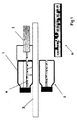
図7に示すように、本発明の好適な実施形態は、バイアルの内容物、例えば製薬製品の溶液、の中の集合体を継続的にオンラインで検出するのに有用である。製品の入っているバイアル1は、概略的に示している生産ライン10に沿って移動する。移動の方向を矢印で示している。測定ステーション11で、バイアルは、垂直に置かれたスキャナ面12の前を通過する。バイアルは、スキャナを通過する間に、ラインの横に置かれたレーザ3により放射されたレーザ4が当てられる。
As shown in FIG. 7, a preferred embodiment of the present invention is useful for continuous online detection of aggregates in the contents of vials, such as pharmaceutical product solutions. The
図8は、事前に充填されたシリンジ13に同様な測定ステーション11を通過させ、そこでレーザ3により放射されるビーム4を当て、シリンジ内の粒子を検出する同様の使用法を示している。溶液内の粒子物質によって可視化されたレーザビーム4は、垂直に配置されたスキャナ12によって走査される。蛋白質の集合体及び/又は濾過分離できるものの様な粒子が検出されると、バイアル又はシリンジは、自動的に排除される。
FIG. 8 shows a similar use for passing a
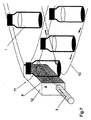
図9に示すように、シリンジ13は、スキャナ面2の上方を移動するベルト14の上に横に寝かせて搬送してもよい。レーザ3は、移動するベルトの横に配置されてビーム4を放射し、ビームはシリンジ内の溶液を貫通する。
As shown in FIG. 9, the
図10は、蛍光を測定するためにキュベットホルダ15に挿入される装置を示している。製品をオンライン分析するための測定ステーションでのように、小さな垂直のスキャナが、試料保持面の横に配置されている。レーザは、ビームをスキャナ面と平行に放射するように配置されている。蛍光励起光源16は、レーザの反対側に配置され、検出器17は、分光蛍光計に蛍光を送る光ファイバーでもよいが、励起ビームから角度をずらして配置されている。この型式の同様の装置を、UV−VIS、円二色性、赤外線又はラマン分光測光法の様な他の分光法に適合させてもよい。
FIG. 10 shows the device inserted into the
蛍光励起は、試料に可視効果を頻繁に作り出し、それはレーザビームが無くてもスキャナによって記録することができる。従って、スキャナと蛍光測定装置の組合せも、本発明の1つの態様である。 Fluorescence excitation frequently creates a visible effect on the sample, which can be recorded by a scanner without a laser beam. Therefore, a combination of a scanner and a fluorescence measuring device is also an aspect of the present invention.
図11に示している本発明の更なる実施形態は、サイズ排除クロマトグラフィ(SEC)、高圧液体クロマトグラフィ(HPLC)、フィールドフローフラクショネーション(FFF)、イオン交換クロマトグラフィ、等電点分離法、又はキャピラリーゾーン電気泳動(CZE)の様な異なる液体クロマトグラフィ法において集合体のオンライン特性判定を行うためのフロースルー装置18である。図12は、図10に示した実施形態での様に追加の蛍光測定装置を備えた同じ装置を示している。
Further embodiments of the present invention shown in FIG. 11 include size exclusion chromatography (SEC), high pressure liquid chromatography (HPLC), field flow fractionation (FFF), ion exchange chromatography, isoelectric focusing, or capillary A flow-through
スキャナによる粒子の検出と可視化の他にも、オンライン装置には、蛍光、UV、動的又は静的光散乱の様な他の検出機構を組み込んでもよい。
図13は、レーザとスキャナを、フロースルー細管20を有する既知の動的又は静的光散乱検出器19の一部として使用したものを示している。可視化スキャナを使用すれば、大きな粒子を分析することができる。スキャナ2は、光散乱検出器19の下に配置され、一方、レーザは、その横に配置されている。このシステムは、特に、フィールドフローフラクショネーションの様なクロマトグラフィ技法に有用である。
In addition to particle detection and visualization with a scanner, the on-line device may incorporate other detection mechanisms such as fluorescence, UV, dynamic or static light scattering.
FIG. 13 shows the use of a laser and scanner as part of a known dynamic or static
図14に示す装置は、基本的には、スキャナ2の上に置くボックス21である。ボックスは、試料キュベット23を挿入するための開口22を有している。ボックスは、試料を貫通してビームを送るように配置されているレーザ24を含む。レーザビーム25は、キュベットの長辺側に平行に試料を通過するが、角度を付けて、例えば対角線状に向けてもよい。また、ボックスの中には、キュベットの横に、分光蛍光計及びUV−Vis単色光からの様な蛍光励起光を放射する光源26が配置されている。キュベットの上には、蛍光放射検出器27が配置されている。光源の反対の側には、UV−Vis吸収検出器28が配置されている。僅かに修正すれば、勿論、この装置をマルチウェルプレートにも使用することができる。
The apparatus shown in FIG. 14 is basically a box 21 placed on the
Claims (9)
レーザビームが試料の上に又は試料を通して案内され、前記試料は、レーザを当てられている間にデジタルスキャナを使って走査されることを特徴とする方法。 In a method for detecting and storing information about the characteristics of an analytical sample solution, in particular a formulation, using a digital scanning device,
A method characterized in that a laser beam is guided over or through a sample, said sample being scanned using a digital scanner while being lasered.
レーザビームを試料の上に又は試料を通して案内するように配置されている光源と、
前記試料の上又は中の前記レーザビームによって作り出される光学的効果を走査するために、前記試料に対して或る相対的な位置に配置されているデジタルスキャナと、
を備えていることを特徴とする装置。 In an apparatus for carrying out the method according to any of claims 1 to 8,
A light source arranged to guide a laser beam over or through the sample;
A digital scanner positioned at a relative position with respect to the sample to scan optical effects created by the laser beam on or in the sample;
A device characterized by comprising:
Applications Claiming Priority (1)
| Application Number | Priority Date | Filing Date | Title |
|---|---|---|---|
| PCT/CH2007/000025 WO2008086632A1 (en) | 2007-01-19 | 2007-01-19 | Method and apparatus for detecting and registering properties of samples |
Publications (2)
| Publication Number | Publication Date |
|---|---|
| JP2010516999A true JP2010516999A (en) | 2010-05-20 |
| JP2010516999A5 JP2010516999A5 (en) | 2012-08-30 |
Family
ID=38522765
Family Applications (1)
| Application Number | Title | Priority Date | Filing Date |
|---|---|---|---|
| JP2009545784A Pending JP2010516999A (en) | 2007-01-19 | 2007-01-19 | Method and apparatus for detecting and recording sample characteristics |
Country Status (7)
| Country | Link |
|---|---|
| US (1) | US9417176B2 (en) |
| EP (1) | EP2106541B1 (en) |
| JP (1) | JP2010516999A (en) |
| CN (1) | CN101583863A (en) |
| ES (1) | ES2662027T3 (en) |
| PL (1) | PL2106541T3 (en) |
| WO (1) | WO2008086632A1 (en) |
Cited By (4)
| Publication number | Priority date | Publication date | Assignee | Title |
|---|---|---|---|---|
| US8315398B2 (en) | 2007-12-21 | 2012-11-20 | Dts Llc | System for adjusting perceived loudness of audio signals |
| US8538042B2 (en) | 2009-08-11 | 2013-09-17 | Dts Llc | System for increasing perceived loudness of speakers |
| US9312829B2 (en) | 2012-04-12 | 2016-04-12 | Dts Llc | System for adjusting loudness of audio signals in real time |
| CN112119339A (en) * | 2018-04-23 | 2020-12-22 | 生德奈股份有限公司 | Method for examining a liquid containing at least one cell and/or at least one particle |
Families Citing this family (3)
| Publication number | Priority date | Publication date | Assignee | Title |
|---|---|---|---|---|
| JP6059872B2 (en) * | 2009-03-04 | 2017-01-18 | マルベルン インスツルメンツ リミテッドMalvern Instruments Limited | Measurement of particle characteristics |
| US10132736B2 (en) | 2012-05-24 | 2018-11-20 | Abbvie Inc. | Methods for inspection of protein particles in a liquid beneficial agent |
| JP6800223B2 (en) * | 2016-10-28 | 2020-12-16 | ベックマン コールター, インコーポレイテッド | Material preparation evaluation system |
Citations (9)
| Publication number | Priority date | Publication date | Assignee | Title |
|---|---|---|---|---|
| JPH0372247A (en) * | 1989-08-12 | 1991-03-27 | Res Dev Corp Of Japan | Apparatus for spectroscopy of highly sensitive for multi-wavelength light emitting fluorescence |
| JPH03197840A (en) * | 1989-12-26 | 1991-08-29 | Canon Inc | Particle analyzing device |
| JPH03293557A (en) * | 1990-04-12 | 1991-12-25 | Hitachi Ltd | Fluorescence detection type electrophoretic apparatus |
| JPH0572179A (en) * | 1991-09-10 | 1993-03-23 | Hitachi Ltd | Detecting device for two-dimensional fluorescent image of nucleic acid and protein |
| JPH06505333A (en) * | 1991-02-01 | 1994-06-16 | ノボ ノルディスク アクティーゼルスカブ | Method and apparatus for inspecting liquid-filled containers |
| US5486693A (en) * | 1994-02-17 | 1996-01-23 | Thermedics Detection Inc. | Detection of turbid contaminants in containers by detecting scattered radiant energy |
| JP2002521660A (en) * | 1998-07-23 | 2002-07-16 | アクシス−シールド・エーエスエー | Agglutination test |
| JP2002228586A (en) * | 2001-01-31 | 2002-08-14 | Hitachi Ltd | Fluorescence measuring instrument and fluorescence measuring method |
| JP2003294604A (en) * | 2002-01-17 | 2003-10-15 | Becton Dickinson & Co | Apparatus and method for imaging particles through flow cell imaging |
Family Cites Families (11)
| Publication number | Priority date | Publication date | Assignee | Title |
|---|---|---|---|---|
| US3624835A (en) * | 1968-11-21 | 1971-11-30 | Science Spectrum | Microparticle analyzer employing a spherical detector array |
| US4221961A (en) * | 1978-10-23 | 1980-09-09 | Industrial Automation Corporation | Electronic bottle inspector having particle and liquid detection capabilities |
| EP0056413A1 (en) * | 1980-07-24 | 1982-07-28 | Labsystems Oy | Method and apparatus for the measurement of the properties of an agglutination |
| AU3057689A (en) * | 1988-02-03 | 1989-08-25 | Cetus Corporation | Apparatus and method for detecting hemagglutination reactions |
| DE4223269A1 (en) * | 1992-07-16 | 1994-01-20 | Krieg Gunther | Identification of molecular compounds by absorption, scattering or fluorescence of liquids in returned drinks bottles - applying laser pulse to test container and separating into different spectral colours using bundle of optical fibres of different length before photomultiplier |
| US5436979A (en) * | 1992-08-21 | 1995-07-25 | Eastman Kodak Company | Process for detecting and mapping dirt on the surface of a photographic element |
| JP3559648B2 (en) * | 1996-04-23 | 2004-09-02 | 株式会社日立製作所 | Capillary array electrophoresis device |
| JP2000510582A (en) * | 1996-04-25 | 2000-08-15 | ゼニコン・サイエンシーズ・コーポレーション | Analyte assays using particulate labeling |
| US6914250B2 (en) * | 1997-03-07 | 2005-07-05 | Clare Chemical Research, Inc. | Fluorometric detection using visible light |
| JP2002221498A (en) * | 2000-11-24 | 2002-08-09 | Sukiyan Technol:Kk | System for detecting foreign matter |
| WO2006023470A1 (en) * | 2004-08-19 | 2006-03-02 | Becton, Dickinson And Company | Apparatus for performing optical measurements on blood culture bottles |
-
2007
- 2007-01-19 US US12/522,877 patent/US9417176B2/en active Active
- 2007-01-19 JP JP2009545784A patent/JP2010516999A/en active Pending
- 2007-01-19 EP EP07700123.8A patent/EP2106541B1/en not_active Not-in-force
- 2007-01-19 CN CNA2007800499751A patent/CN101583863A/en active Pending
- 2007-01-19 ES ES07700123.8T patent/ES2662027T3/en active Active
- 2007-01-19 PL PL07700123T patent/PL2106541T3/en unknown
- 2007-01-19 WO PCT/CH2007/000025 patent/WO2008086632A1/en active Application Filing
Patent Citations (9)
| Publication number | Priority date | Publication date | Assignee | Title |
|---|---|---|---|---|
| JPH0372247A (en) * | 1989-08-12 | 1991-03-27 | Res Dev Corp Of Japan | Apparatus for spectroscopy of highly sensitive for multi-wavelength light emitting fluorescence |
| JPH03197840A (en) * | 1989-12-26 | 1991-08-29 | Canon Inc | Particle analyzing device |
| JPH03293557A (en) * | 1990-04-12 | 1991-12-25 | Hitachi Ltd | Fluorescence detection type electrophoretic apparatus |
| JPH06505333A (en) * | 1991-02-01 | 1994-06-16 | ノボ ノルディスク アクティーゼルスカブ | Method and apparatus for inspecting liquid-filled containers |
| JPH0572179A (en) * | 1991-09-10 | 1993-03-23 | Hitachi Ltd | Detecting device for two-dimensional fluorescent image of nucleic acid and protein |
| US5486693A (en) * | 1994-02-17 | 1996-01-23 | Thermedics Detection Inc. | Detection of turbid contaminants in containers by detecting scattered radiant energy |
| JP2002521660A (en) * | 1998-07-23 | 2002-07-16 | アクシス−シールド・エーエスエー | Agglutination test |
| JP2002228586A (en) * | 2001-01-31 | 2002-08-14 | Hitachi Ltd | Fluorescence measuring instrument and fluorescence measuring method |
| JP2003294604A (en) * | 2002-01-17 | 2003-10-15 | Becton Dickinson & Co | Apparatus and method for imaging particles through flow cell imaging |
Cited By (9)
| Publication number | Priority date | Publication date | Assignee | Title |
|---|---|---|---|---|
| US8315398B2 (en) | 2007-12-21 | 2012-11-20 | Dts Llc | System for adjusting perceived loudness of audio signals |
| US8538042B2 (en) | 2009-08-11 | 2013-09-17 | Dts Llc | System for increasing perceived loudness of speakers |
| US9820044B2 (en) | 2009-08-11 | 2017-11-14 | Dts Llc | System for increasing perceived loudness of speakers |
| US10299040B2 (en) | 2009-08-11 | 2019-05-21 | Dts, Inc. | System for increasing perceived loudness of speakers |
| US9312829B2 (en) | 2012-04-12 | 2016-04-12 | Dts Llc | System for adjusting loudness of audio signals in real time |
| US9559656B2 (en) | 2012-04-12 | 2017-01-31 | Dts Llc | System for adjusting loudness of audio signals in real time |
| CN112119339A (en) * | 2018-04-23 | 2020-12-22 | 生德奈股份有限公司 | Method for examining a liquid containing at least one cell and/or at least one particle |
| JP2021522474A (en) * | 2018-04-23 | 2021-08-30 | ツィテナ ゲーエムベーハーCytena Gmbh | A method for inspecting a liquid containing at least one cell and / or at least one particle |
| US11624694B2 (en) | 2018-04-23 | 2023-04-11 | Cytena Gmbh | Method for examining a liquid which contains at least one cell and/or at least one particle |
Also Published As
| Publication number | Publication date |
|---|---|
| PL2106541T3 (en) | 2018-05-30 |
| US9417176B2 (en) | 2016-08-16 |
| EP2106541A1 (en) | 2009-10-07 |
| EP2106541B1 (en) | 2017-12-13 |
| WO2008086632A8 (en) | 2009-08-13 |
| CN101583863A (en) | 2009-11-18 |
| ES2662027T3 (en) | 2018-04-05 |
| US20100102247A1 (en) | 2010-04-29 |
| WO2008086632A1 (en) | 2008-07-24 |
Similar Documents
| Publication | Publication Date | Title |
|---|---|---|
| EP3071951B1 (en) | Optical engine for flow cytometer, flow cytometer system and methods of use | |
| EP2948756B1 (en) | Optical measuring apparatus and method for the analysis of samples contained in liquid drops | |
| US9417176B2 (en) | Method and apparatus for detecting and registering properties of samples | |
| EP1935983B1 (en) | Method for determination of biological particles in blood | |
| JP2008281571A (en) | Apparatus for reading signals generated from resonance lightscattered particle labels | |
| JP5174035B2 (en) | 2D array imaging | |
| JP4600573B2 (en) | Optical measurement apparatus, wavelength calibration method and optical measurement method for photodetector | |
| US20190170642A1 (en) | Array based sample characterization | |
| Gessner et al. | Identification of biotic and abiotic particles by using a combination of optical tweezers and in situ Raman spectroscopy | |
| EP0592624A1 (en) | Diagnostic microbiological testing apparatus and method | |
| JP2007524389A (en) | Wide-field method for detecting pathogenic microorganisms | |
| US9488579B2 (en) | Optical measuring apparatus and method for the analysis of samples contained in liquid drops | |
| US20240011884A1 (en) | Systems and methods for identifying protein aggregates in biotherapeutics | |
| US20150308944A1 (en) | Optical measuring apparatus and method for the analysis of samples contained in liquid drops | |
| EP1472913B1 (en) | Analysis method | |
| US20200379227A1 (en) | Method For Analyzing Fluorescent Particles in an Immunoassay | |
| JP2004226408A (en) | Method and apparatus for observing reaction of specimen | |
| JPH01102342A (en) | Fluoro-microscopic spectral method and apparatus | |
| KR102441156B1 (en) | multiplexing analyzing apparatus using muiti-wavelength light | |
| JP2003021593A (en) | Specimen examination device |
Legal Events
| Date | Code | Title | Description |
|---|---|---|---|
| A131 | Notification of reasons for refusal |
Free format text: JAPANESE INTERMEDIATE CODE: A131 Effective date: 20120117 |
|
| A601 | Written request for extension of time |
Free format text: JAPANESE INTERMEDIATE CODE: A601 Effective date: 20120412 |
|
| A602 | Written permission of extension of time |
Free format text: JAPANESE INTERMEDIATE CODE: A602 Effective date: 20120419 |
|
| A601 | Written request for extension of time |
Free format text: JAPANESE INTERMEDIATE CODE: A601 Effective date: 20120515 |
|
| A602 | Written permission of extension of time |
Free format text: JAPANESE INTERMEDIATE CODE: A602 Effective date: 20120522 |
|
| A601 | Written request for extension of time |
Free format text: JAPANESE INTERMEDIATE CODE: A601 Effective date: 20120608 |
|
| A602 | Written permission of extension of time |
Free format text: JAPANESE INTERMEDIATE CODE: A602 Effective date: 20120615 |
|
| A521 | Written amendment |
Free format text: JAPANESE INTERMEDIATE CODE: A523 Effective date: 20120706 |
|
| A524 | Written submission of copy of amendment under section 19 (pct) |
Free format text: JAPANESE INTERMEDIATE CODE: A524 Effective date: 20120706 |
|
| A131 | Notification of reasons for refusal |
Free format text: JAPANESE INTERMEDIATE CODE: A131 Effective date: 20130204 |
|
| A601 | Written request for extension of time |
Free format text: JAPANESE INTERMEDIATE CODE: A601 Effective date: 20130418 |
|
| A602 | Written permission of extension of time |
Free format text: JAPANESE INTERMEDIATE CODE: A602 Effective date: 20130425 |
|
| A601 | Written request for extension of time |
Free format text: JAPANESE INTERMEDIATE CODE: A601 Effective date: 20130604 |
|
| A602 | Written permission of extension of time |
Free format text: JAPANESE INTERMEDIATE CODE: A602 Effective date: 20130611 |
|
| A521 | Written amendment |
Free format text: JAPANESE INTERMEDIATE CODE: A523 Effective date: 20130704 |
|
| A02 | Decision of refusal |
Free format text: JAPANESE INTERMEDIATE CODE: A02 Effective date: 20131216 |